

Teledyne Echotrac MKIII Operator's Manual

ECHOTRAC MKIII
OPERATOR'S MANUAL
Version: 4.06
Teledyne Odom Hydrographic
Teledyne Marine
Fabriksvangen 13
3550 Slangerup
Denmark
Telephone: +45 47 38 00 22 Fax: +45 47 38 00 66
www.teledynemarine.com/odom-hydrographic/
Number of pages: 48
Date: 21 January 2019

Echotrac MKIII Operator's Manual 4.06
Page 2 of 48
January 21, 2019
Revision History
Version
Date
Author
Remarks
0.1
09-19-2002
P. Oostenrijk
Initial version – draft
1.0
01-28-2003
S.F. Apsey
1.1
03-27-2003
S.F. Apsey
Updated manual for firmware version 2.07;Changed default of
Tracking Gate. Added Skip Alarms. Added Grey shades.
1.2
09-09-2003
S.F. Apsey
Updated manual for firmware version 2.14: Added Subottom TVG,
SB TVG Range, Pre Amp Gain, Dual Light Shade parameters.
1.4
02-16-2005
S.F. Apsey
Changes from Echotrac MKIII 3.05 to 3.06:
1-When the Echotrac MKIII is set to read in heave through com4 it
will check to see if the first character in the string is an ‘R’ (remote
heave). If the first character is an ‘R’ the Echotrac will use the
remote heave value for corrections otherwise the Echotrac will use
the local heave.
2-Added a parameter called HEAVECORR. This parameter will
heave correct the chart when turned on or not heave correct the
chart if turned off. The selection of the ‘Heave Out’ serial string will
now no longer affect the heave correction on the chart.
3-The parameter DIGILINE will now have a range of
0,1,2,3,4,5,6,7,8,9,10 instead of on or off. When set to 0 the
digitizer line will not be printed. If set to any other number, the
digitizer line will be printed that many units above the raw bottom.
4-The parameter LIGHTSHADE will now have the selections Chnl2
Dark, Chnl1 Dark, Chnl2 Only and Chnl1 Only. This will reflect how
the data and what data will be printed when both channels are
turned on. If Chnl2 Dark is selected, Channel 2 will be printed
darker than Channel 1. If Chnl2 only is selected then only Channel
2 will be printed.
3.08
04-14-2005
P. Oostenrijk
Updated manual for firmware version 3.08
Added section on how to request parameter settings through the
serial port.
3.20
01-16-2006
P. Oostenrijk
Added UDP port, Hours of operation, Packet size 8/16 bits,
outputstring DESO DDV, print German Help.
3.22
02-28-2006
P. Oostenrijk
New optimized Deso command handling routines.
Re-enabled TVGgainref and Trackinggate in Echotrac Control
program. Improved annotation handling.
3.23
05-22-2006
P. Oostenrijk
Improved Echotrac Control program network detection interface.
Low Frequency pulse width increased to 256.
Corrected auto-scaling when draft and index are used.
Added support for Echotrac CVM.
3.25
08-03-2006
P. Oostenrijk
Fixed: Stopping the synchronization process disabled
communication with Echotrac.
Added compatibility check and warning for Echotrac Control
Program version and Echotrac firmware version.
If during synchronization a parameter is missing, the parameter
name is now displayed.
Improved version control in firmware and diagnostic window.
Added Echotrac and Subbottom mode to Control Program. This is
not supported on the MK3.
Added Datacheck for GPS and Heave.
Depth values are red in case of depth alarm.
Added transparency feature on depth monitor window.
Added support for CV100.
Added Power & Gain control to Depth Monitor window.
3.26
09-07-2006
P. Oostenrijk
Updated to 3.26 for Echotrac firmware version compliance.

Echotrac MKIII Operator's Manual 4.06
Page 3 of 48
January 21, 2019
Revision History
Version
Date
Author
Remarks
3.27
09-25-2006
P. Oostenrijk
When a menu parameter value is changed, only the value is
highlighted. But upon entering the edit mode for the menu value
almost instantly the entire menu row would be highlighted. The
problem appears when DESO_DDV+C is selected and Atlas Susy
sends event commands to the MK3.
3.28
01-10-2007
P. Oostenrijk
Improved verification of power settings when scale changes occur.
3.29
05-22-2007
P. Oostenrijk
Added description for Missed Returns and Mode on Setup tab.
Minor change in Grey Shades description. Updated COM port's
baudrate options to include 38400.
Removed chapter Overview Parameters and Settings. This is now
refers to the Technical Specification Ethernet Interface document.
4.00
02-19-2008
P. Oostenrijk
Updated Odom Title and Logo on cover page.
Updated Header and Footer according to new template.
Updated uploading firmware and upgrading DSP firmware.
4.01
02-25-2008
P. Oostenrijk
Updated document version to match software/firmware version.
4.02
03-18-2008
P. Oostenrijk
Added support of extra fine scale grid.
Added support for DESO DDV outputstring for all sounders.
4.03
05-23-2008
P. Oostenrijk
Updated Scale change functionality.
Updated CVM channel handling as 1 and 2 instead of 1 and 3.
4.04
19-12-2016
A. Moeller
Updated Odom logo and front page.
Updated header and footer format.
Updated 1.5 LCD Chart Panel.
Updated wording in 2.3.7 VGA.
4.05
A. Moeller
Contact details updated (page 1).
5.3.2.3: Expanded with two paragraphs and table of pulse widths at
certain frequencies.
Section 9.2: corrected numbered list (no. “13” was repeated).
App. A added with support and service details.
4.06
21-01-2019
A. Moeller
Updated support e-mail throughout document.
Warning, Caution, and Note boxes added throughout document
where relevant.
1.2 Echotrac MKIII Operator’s Manual – new section about the
purpose, scope, warnings and notes, etc.
4, 5, and 7: Somewhat rearranged, reworded.
App. A LCD15 Module. NEW.
App. B: AUX Modification for SILAS Output. NEW.
© TELEDYNE ODOM HYDROGRAPHIC, INC. 2016
All rights are reserved. Reproduction in whole or in part is prohibited without the prior written consent of the
copyright owner.
The information presented in this document does not form part of any quotation or contract, is believed to be
accurate and reliable, and may be subject to change without notice. The publisher will not accept any liability
for any consequence of its use. Publication thereof does not convey nor imply any license under patent- or
other industrial or intellectual property rights.


Echotrac MKIII Operator's Manual 4.06
Page 5 of 48
January 21, 2019
CONTENTS
1 Introduction......................................................................................................................................................7
1.1 Echotrac MKIII.............................................................................................................................................7
1.1.1 Dual Frequency Operation ...................................................................................................................7
1.1.2 Printer Mechanism ...............................................................................................................................7
1.1.3 Display .................................................................................................................................................7
1.1.4 LCD Chart Panel ..................................................................................................................................7
1.1.5 Keypad .................................................................................................................................................7
1.1.6 Receivers .............................................................................................................................................7
1.1.7 Transmitter ...........................................................................................................................................7
1.1.8 Communication Ports...........................................................................................................................8
1.2 Echotrac MKIII Operator’s Manual ..............................................................................................................8
1.2.1 Purpose................................................................................................................................................8
1.2.2 Scope ...................................................................................................................................................8
1.2.3 Warnings, Cautions, and Notes ...........................................................................................................8
1.2.4 Glossary ...............................................................................................................................................8
2 Installation........................................................................................................................................................9
2.1 Echotrac DF 3200 MKIII Recorder Installation ............................................................................................9
2.1.1 Power ...................................................................................................................................................9
2.1.2 Cabling .................................................................................................................................................9
2.1.3 Fuses ...................................................................................................................................................9
2.1.4 Chart Paper........................................................................................................................................10
2.2 Transducer Installation ..............................................................................................................................11
2.2.1 "THROUGH HULL" Installation ..........................................................................................................12
2.2.2 "SEA CHEST" Installation ..................................................................................................................12
2.2.3 "OVER-THE-SIDE" Transducer Installation .......................................................................................12
2.2.4 “HULL MOUNT” Installation ...............................................................................................................12
2.3 Echotrac MKIII Cable Connections ...........................................................................................................13
2.3.1 Serial 1 ...............................................................................................................................................13
2.3.2 Serial 2 ...............................................................................................................................................13
2.3.3 Serial 3 ...............................................................................................................................................13
2.3.4 Serial 4 ...............................................................................................................................................13
2.3.5 GPS In................................................................................................................................................13
2.3.6 GPS Out.............................................................................................................................................14
2.3.7 VGA....................................................................................................................................................14
2.3.8 LAN ....................................................................................................................................................14
2.3.9 Aux .....................................................................................................................................................14
2.3.10 TX1 .................................................................................................................................................15
2.3.11 TX2 .................................................................................................................................................15
2.3.12 DC ..................................................................................................................................................15
2.3.13 AC...................................................................................................................................................15
3 Quick Start Operating Procedures...............................................................................................................16
4 Chart Recorder Controls...............................................................................................................................17
4.1 ON/OFF.....................................................................................................................................................17
4.2 FEED.........................................................................................................................................................17
4.3 TAKE-UP...................................................................................................................................................17
4.4 LIGHT........................................................................................................................................................17
5 Display Panel Controls..................................................................................................................................18
5.1 Analog Controls.........................................................................................................................................18
5.1.1 POWER..............................................................................................................................................18

Echotrac MKIII Operator's Manual 4.06
Page 6 of 48
January 21, 2019
5.1.2 Transmitter and Receiver Controls ....................................................................................................19
5.1.3 MARK.................................................................................................................................................19
5.2 Parameter Entry System ...........................................................................................................................20
5.2.1 System Menu .....................................................................................................................................20
5.2.2 Setup Menu........................................................................................................................................22
5.2.3 Calibrate Menu...................................................................................................................................25
5.2.4 Chart Menu ........................................................................................................................................26
5.2.5 Communications Menu ......................................................................................................................28
5.2.6 Diagnostic Menu ................................................................................................................................29
6 Operating Procedures ...................................................................................................................................31
6.1 Shallow Water Operation ..........................................................................................................................31
6.2 Deep Water Operation ..............................................................................................................................31
6.3 Calibration .................................................................................................................................................32
7 Data I/O ...........................................................................................................................................................33
7.1 Serial Ports – Serial 1................................................................................................................................33
7.1.1 SERIAL OUTPUT STRING FORMATS .............................................................................................33
7.1.2 DESO DDV ........................................................................................................................................36
7.1.3 DESO COMMANDS...........................................................................................................................37
7.1.4 NMEA DBS ........................................................................................................................................37
7.2 Serial Data Input / Chart Annotation..........................................................................................................37
7.2.1 External Serial Control of Echotrac Parameters ................................................................................38
8 Overview parameters and settings ..............................................................................................................40
8.1 External Ethernet Control of Echotrac Parameters ...................................................................................40
8.2 Serial Ports – Serial 2................................................................................................................................40
8.3 Serial Ports – Serial 3................................................................................................................................40
8.4 Serial Ports – HEAVE................................................................................................................................40
8.5 ETHERNET Port .......................................................................................................................................40
9 Uploading Firmware ......................................................................................................................................41
9.1 Upgrading Motorola Processor Firmware..................................................................................................41
9.2 Upgrading DSP Firmware and Transceiver Processor Firmware .............................................................41
Appendix A – LCD15 Module................................................................................................................................43
A.1 Connections to the MKIIIE.........................................................................................................................43
A.1.1 Mouse and Keyboard Considerations ................................................................................................44
A.1.2 Starting and Shutting down the LCD15 Module .................................................................................44
A.1.3 Use of USB Memory Stick..................................................................................................................44
A.1.4 LCD15 Brightness Control .................................................................................................................44
A.2 Connecting to the MKIIIE...........................................................................................................................44
A.3 Making Changes To The Embedded Software Configuration ...................................................................45
A.3.1 Enhanced Write Filter.........................................................................................................................45
A.3.2 File Locations .....................................................................................................................................45
A.3.3 Installing Programs ............................................................................................................................45
Appendix B – AUX Modification for SILAS Output.............................................................................................46
Appendix C – Support and Service......................................................................................................................48
C.1 Support......................................................................................................................................................48
C.2 Returning Goods for Service.....................................................................................................................48

Echotrac MKIII Operator's Manual 4.06
Page 7 of 48
January 21, 2019
1 INTRODUCTION
1.1 Echotrac MKIII
The Echotrac MKIII professional grade echo sounder
Recorder, Digitizer, Transceiver, utilizes multiple
processors including two dedicated Digital Signal
Processors (DSPs), working in concert to accomplish
specific analysis tasks while communicating effectively on a
real-time basis in order to assure accurate measurements
under difficult sea conditions and over all types of seabed.
1.1.1 Dual Frequency Operation
Two simultaneously transmitted frequencies are
selectable in 100 Hz steps in the following bands: High
Band - from 100 kHz to 1000 kHz and in the Low Band –
from 10 kHz to 50 kHz.
1.1.2 Printer Mechanism
The high-resolution thin-film thermal print head (216mm
(8.5") wide, 8 dots per mm (203/in.) is capable of printing
returns in up to 16 gray shades. Because of its construction,
the print head consumes very little power compared to
previous technologies. A stepper motor drives the print
mechanism while a DC motor and associated slipping-clutch mechanism re-winds the printed chart independently.
1.1.3 Display
Transflective, Back-lighted Graphical LCD Module (64 x 240 dots). The display shows six dot rows, has an on
board controller and LED backlighting. The transflective display was chosen because of its excellent visibility in all
light conditions from bright sun to darkened wheelhouse.
1.1.4 LCD Chart Panel
An alternative to the printer module is the LCD chart panel. It is a 1024x768 pixel color active matrix display with a
500 NIT back light. The LCD chart panel records echosounder data on internal drives. An export is possible via
the LCD chart panel’s USB interface or LAN interface.
1.1.5 Keypad
The 18 key-sealed micro-switch unit has good tactile feel and audible feedback. The keypad is used for direct
parameter value entry and functional control of the sounder from the front panel.
1.1.6 Receivers
The MKIII gives immediate control of Receiver Gain via continuously variable front panel mounted potentiometers.
The unit incorporates multiple, selectable TVG curves (10 log, 20 log, 30 log, and 40 log) and AGC as well.
1.1.7 Transmitter
Transmit frequencies are digitally synthesized and based on the stable frequency characteristics of a crystal
controlled clock oscillator. Transmitted power for both high and low channels is individually adjustable via front panel
mounted controls. Power is adjustable from the minimum of only 2 watts in high frequency shallow water
applications to over 2000 watts in low frequency deepwater uses. Transmit Pulse Width is variable either
automatically (actual value dependent on frequency and depth) or manually by keypad entry.

Echotrac MKIII Operator's Manual 4.06
Page 8 of 48
January 21, 2019
1.1.8 Communication Ports
Warnings alert the user to potential harm to personnel. Ignoring warnings may lead to
injury, health hazards, or death.
Cautions alert the user to improper use of the system. Ignoring cautions may lead to
accidental damage to the equipment or loss of data.
Notes provide additional system or operating information not related to the safety of personnel or
equipment.
The Echotrac MKIII has 4 serial ports that can be configured to interface with computers, positioning systems,
motion reference units and remote displays. The MKIII also has an Ethernet port that outputs the 16 bit samples
of the acoustic data for further processing or visualization.
1.2 Echotrac MKIII Operator’s Manual
1.2.1 Purpose
The purpose of this document is to explain the features and operation of the Echotrac MKIII.
1.2.2 Scope
The content of this document is focused on the end-user.
1.2.3 Warnings, Cautions, and Notes
Throughout the manual the following definitions apply and in the format shown.
If you require additional information or need clarification of any part of this document, please contact the customer
support hotline
Europe: +45 20 999 088
USA: +1 805 233 3900
E-mail: reson-support@teledyne.com
1.2.4 Glossary
DBS Depth Below Surface
DBT Dual Bottom Tracking
DSP Digital Signal Processor
NMEA National Marine Electronics Association
SBT Single Bottom Tracking
TVG Time Varied Gain
VDC Volts Direct Current
Echotrac MKIII Operator's Manual 4.06
Page 9 of 48
January 21, 2019
2 INSTALLATION
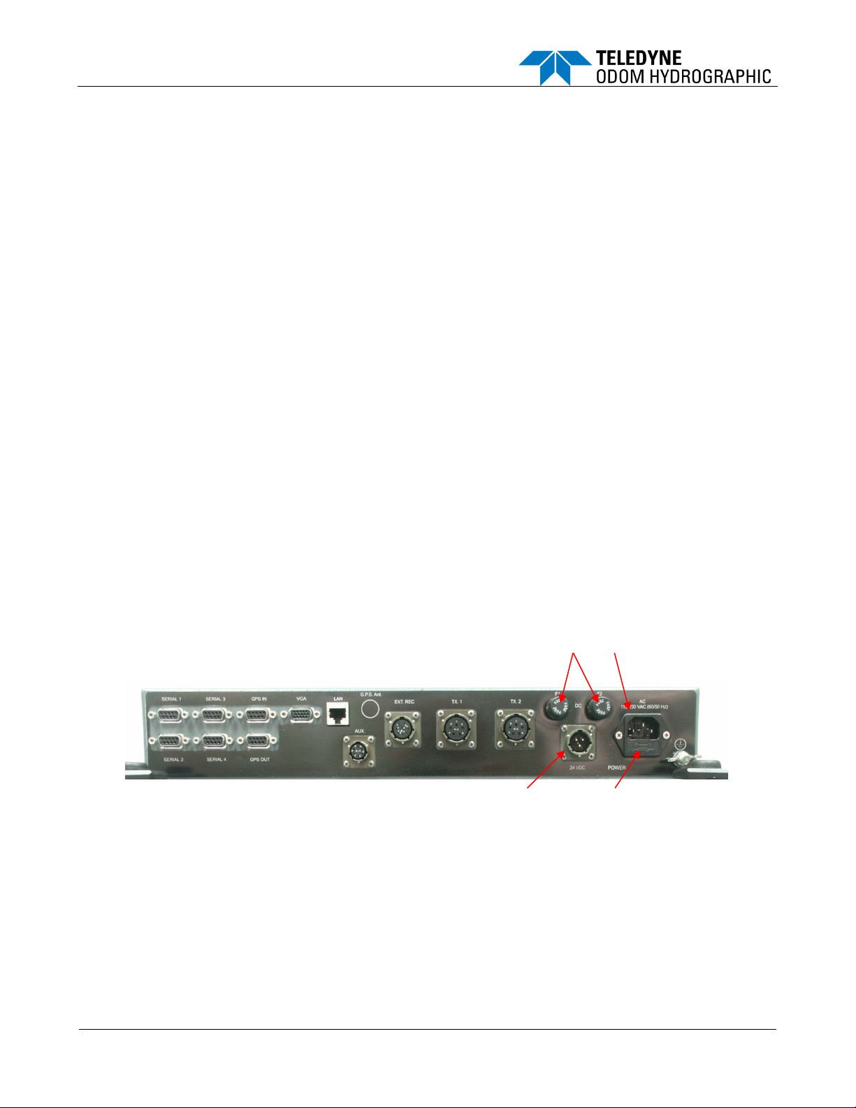
DC Fuses
DC Power Connector
AC Fuse Compartment
AC Power Conn.
2.1 Echotrac DF 3200 MKIII Recorder Installation
The Recorder is a flexible unit designed for tabletop, rack, or bulkhead mounting. Rack mounting can be
accommodated with the included special hardware, while bulkhead mounting requires ordering additional optional
hardware. Where tabletop mounting is preferred, it is highly recommended that the unit be secured with external
'tie-downs' for rough seas or heavy swells.
2.1.1 Power
The MKIII can be powered by either AC or DC power sources. Switch over between sources is automatic. DC
operation requires an input voltage between 18 and 29 VDC (nominal 24 VDC). Average power consumption is
approximately 75 watts. Frequently, power is derived from two 12 V lead-acid batteries connected in series. Two
"car" batteries (24V configuration), fully charged, and in good condition, can normally power a unit for a full day
without re-charging.
If using an AC source, the unit’s internal switcher accommodates either 110 or 230 VAC (50/60HZ) operation without
operator intervention. Regardless of the input source (AC or DC), the input power should be well regulated and
monitored closely for voltage transients, spikes, etc. Regulated DC supplies should be able to source a short
duration in-rush current spike of approximately 6 amps and an average current load of 3 amps. In the case of
"charger" type (unregulated) supplies, the output should be "floated" across a battery load and not connected solely
to the echo sounder’s DC input. Details of the power cable are given in section 2.3. Should the DC input voltage
polarity be applied in reverse, an audible alarm within the unit will sound regardless of the POWER switch setting. In
the event that the input voltage drops below the minimum threshold, the unit will automatically shut down.
2.1.2 Cabling
All cabling is via the connectors located in the recessed panel at the top rear of the unit. A view of the connector
arrangement is shown in Figure 2.1. Cable details are given in section 2.3. Care should be taken to route cables
using horizontal and vertical runs wherever possible. Avoid paths that run adjacent to transmitter feeder cables or
close to heat radiating elements such as steam pipes. For permanent installations, cables should be clamped at
regular intervals (1m) along their complete lengths.
Figure 1: Cabling
2.1.3 Fuses
For DC operation, both the positive and return lines are protected by fast blow standard glass tube (5-Amp/250
Volts) fuses. The two externally accessed fuses are mounted on the rear connector panel. The negative fuse
protects the unit from damage resulting from contact with external peripherals that do not share a common return
path potential. A 5-amp fuse is included in the AC input connector as well.
Echotrac MKIII Operator's Manual 4.06
Page 10 of 48
January 21, 2019
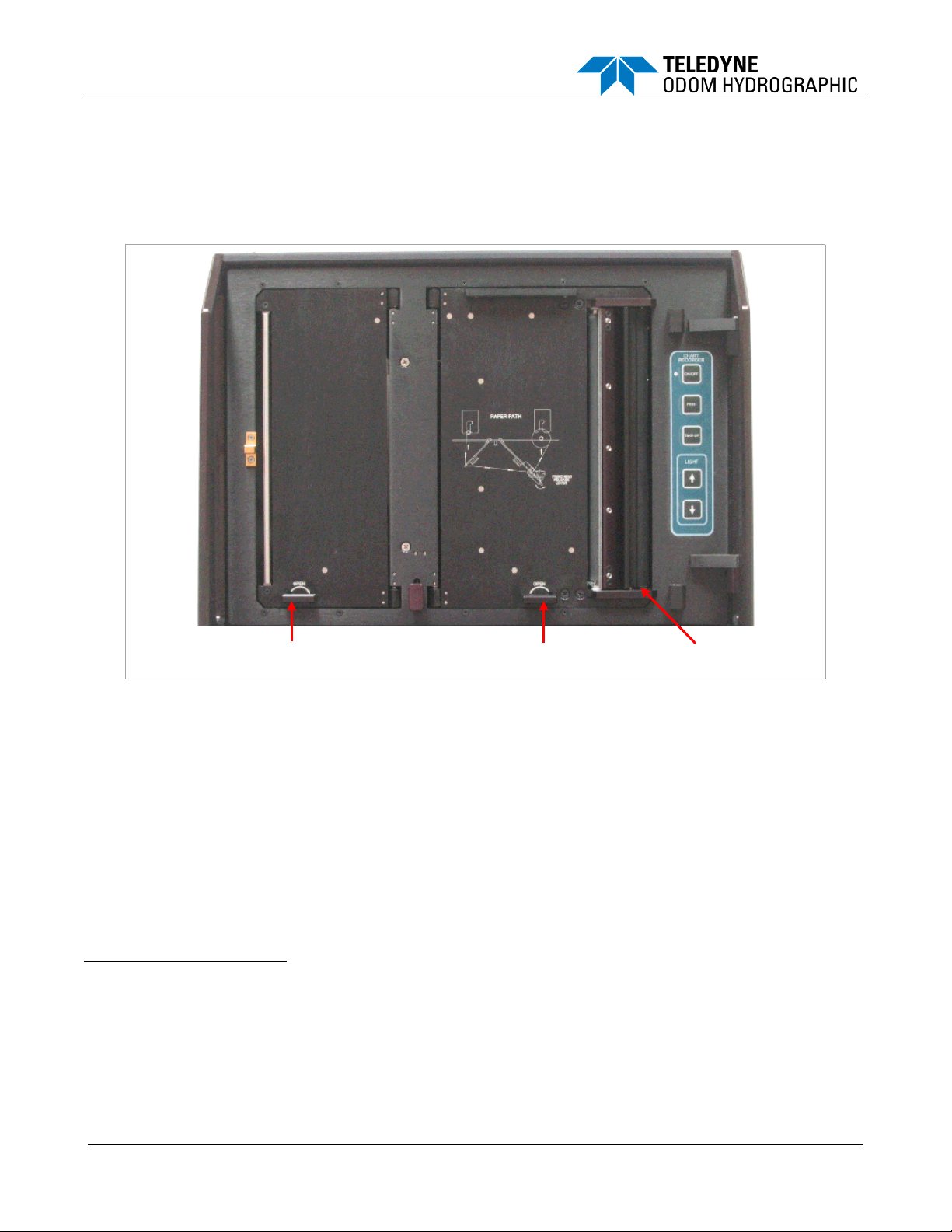
2.1.4 Chart Paper
Print Head release lever
Supply Door release lever
Take-Up Door release lever
2.1.4.1 General Paper Description
The Echotrac MKIII uses either thermal film or high quality thermal paper as the recording media for the analog
chart. The rolls are 216mm (8.5") wide and contain approximately 52m (170') of paper (film rolls are approximately
30m long). The inside diameter of the core is 12.7mm (½"), and the outside diameter of the roll is about 64mm (2.5").
Figure 2: Chart Paper
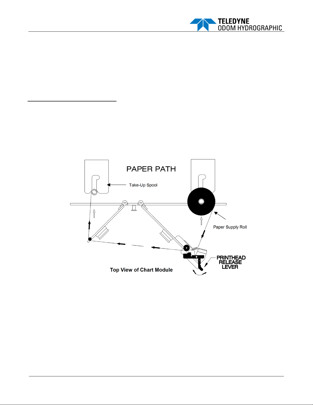
2.1.4.2 Loading paper
Loading paper is a multi-step process, but it need not be a difficult one if care is taken to assure that each step is
accomplished properly. As in almost all thermal recorders (including FAX machines), paper is sourced from a
supply roll, where it passes over a roller, which moves the paper past the thermal print head. A print head release
mechanism lifts the head away from the roller to assist in initial paper loading.
The Echotrac’s printed chart paper is taken up on a take-up spool behind the paper access door at the far left of
the chart panel. The motor that drives the take up spool does not advance the paper, as is the case in some echo
sounders. Movement of paper across the print head is accomplished by the stepper motor. In this configuration,
previously printed chart can be pulled from the take up assembly for review and simply re-wound without
disturbing the recording process.
Loading Paper Procedures:
1) Open the plexiglass chart door by pulling on the handle on the left side and remove it by lifting up on the hinged side.
2) If paper has been previously installed in the unit, place the power switch in the STANDBY position. Press the CHART
FEED switch until sufficient paper has been advanced to clear any previously recorded data. Cut the paper at some
point after the recorded data and press the Chart Take-up switch. This will allow the take-up mechanism to wind up
the recorded chart.
3) Locate the print head release lever on the right side of the print head. Move the lever to the right in order to lift the print
head away from the roller.
Echotrac MKIII Operator's Manual 4.06
Page 11 of 48
January 21, 2019
4) To gain access to the supply roll turn the supply side door release lever located on the lower right side of the chart
panel counter clockwise and pull the door open.
5) Remove any remaining paper from the paper path and remove the spent supply roll from the holder
mechanism by grasping the core and pushing it to the left and pulling out.
6) To gain access to the take-up roll turn the take-up door release lever located on the lower left side of the chart
panel clockwise and pull the door open.
7) Remove the take-up roll by grasping it, pushing it to the left, and pulling out. To remove the old paper from the
take up spool, spin the take-up spool in the opposite direction the paper is wound onto the take-up spool.
Remove the plastic end cap using a twisting motion and pull the paper off.
To Install a Fresh Paper Supply Roll:
8) Remove the source paper ends from the spent core and insert them into a new paper supply roll.
9) Insert the roll in the slots until it reaches the end and shift to the right, locking into place. Make sure the paper
is feeding from the right side of the roll.
10) Thread the paper past the print head and towards the take-up side as indicated in the paper path drawing.
11) The paper can be attached to the take-up spool either with a small piece of tape or by inserting the paper in the
slot of the take-up spool. Inserting the paper in the slot requires folding up the edges of the paper. Replace the
end cap to the take up spool and insert the take-up roll into the chart the same way as the supply roll.
12) Close both doors and press the feed button until the paper is aligned. Close the print head release lever. Now
the unit is ready for normal operation.
2.2 Transducer Installation
Proper mounting of the transducer is a crucial part of the installation of any "survey" echo sounder. An improperly
mounted transducer will result in poor system operation and unacceptable data quality.
In the case of temporary installations, the transducer may be mounted over-the-side. In permanent installations and
“class 1 surveys", hull mounts are generally preferred and often required. In either case, transducers should be
mounted at least 0.3 meters below the waterline. In cases where "over-the-side" mounts are exposed to wave action,
ensure that the transducer is mounted sufficiently deep so that it does not break the surface during vessel roll motions.
A preferred mounting location is near the keel of the vessel, in an area where the planning attitude of the hull at
speed, and the pitch and roll angles of the vessel in seas, have the least effect. The transducer should be mounted
far enough aft of the bow so that bubbles generated by the bow wave will not pass over the face of the unit.
Figure 3: Chart Module Top View
Echotrac MKIII Operator's Manual 4.06
Page 12 of 48
January 21, 2019
Transducers should be located away from sources of turbulence and cavitation bubbles such as propellers, bow
Care should be taken to protect the transducer from damage and turbulence by installing
a fairing with a sloping forward edge ahead of the unit.
The fairing has the dual effect of minimizing possible strike damage and smoothing the
flow of water over the face of the transducer.
Care should be taken to assure adequate protection for the transducer cable, particularly
at the point where the cable leaves the transducer body.
thrusters, and hull protrusions. Considerations should also be given to sources of mechanical noise generated within
the vessel (engines, props, pumps, generators, etc.). In some severe cases of mechanically coupled noise,
vibration-isolating mounts may be required to decouple the transducer from the hull.
Transducer mounting can be accomplished in many different ways. The following four sections show common
configurations.
2.2.1 "THROUGH HULL" Installation
The topside of the transducer is accessible from inside the vessel while the transducer face is directly exposed to
the water.
2.2.2 "SEA CHEST" Installation
In a "sea chest" mount, a fluid-filled enclosure large enough to contain the entire transducer is attached to the outer
hull of the vessel. The outer hull is removed within the area of the chest and replaced with an acoustically clear
"window", which is mounted flush with the hull immediately below the chest. Depending on construction, the material
selected for the acoustic window, and the draft of the vessel, access can often be gained to the transducer from
inside the hull without putting the vessel in dry-dock. In most installations, a water-filled standpipe is incorporated
into the "sea chest" design in order to provide hydrostatic pressure equalization. Transducer cables generally leave
these assemblies through “stuffing tubes” designed to maintain the watertight integrity of the chest.
2.2.3 "OVER-THE-SIDE" Transducer Installation
A temporary mount of this type is frequently constructed by welding a length of pipe to a flat plate that has been
drilled to accommodate the mounting points of the transducer. This length of pipe should be chosen to position
the transducer well below the waterline. A sturdy support on the vessel should be selected for the attachment
point of the pipe. Guy lines are usually attached at the transducer plate and run fore and aft to tie-points on the
gunnels. The guy lines and topside fixing point help to maintain a stable, horizontal transducer attitude.
2.2.4 “HULL MOUNT” Installation
Transducers that are “streamlined” and can be mounted directly to the outside of the hull or transducers that are fitted
into streamlined fairings welded or otherwise attached to the outside of the hull, often make for excellent installations.
The advantage here is that the radiating face of the transducer is generally below the “bubble stream” in clear water
and no acoustic window or transducer tank is involved to create extra reverberation (ringing). This type of installation
requires a stuffing tube to be installed in the hull in order to allow the transducer cable to penetrate the hull.
In all of the above installations, particular care should be taken to assure that the transducer radiating
face remains as parallel to the water surface as possible while the vessel is underway.

Echotrac MKIII Operator's Manual 4.06
Page 13 of 48
January 21, 2019
2.3 Echotrac MKIII Cable Connections
Connector PN
Pin Number
Signal Description
DB9 Male
2
Transmitted data from Echotrac MKIII
3
Received data to Echotrac MKIII
5
GND
Connector PN
Pin Number
Signal Description
DB9 Male
2
Transmitted data from Echotrac MKIII
3
Received data to Echotrac MKIII
5
GND
Connector PN
Pin Number
Signal Description
DB9 Male
3
Data from the positioning system to the Echotrac MKIII
5
GND
Connector PN
Pin Number
Signal Description
DB9 Male
3
Data from the motion sensor to the Echotrac MKIII
5
GND
Connector PN
Pin Number
Signal Description
DB9 Male
2
Transmitted data to the Internal GPS
3
Received data from the Internal GPS
5
GND
2.3.1 Serial 1
Serial 1 is the main communication port to and from the Echotrac MKIII. Use this port to receive depth values,
send annotation information, change parameters, and to upgrade the firmware.
2.3.2 Serial 2
Serial 2 is used for connecting a remote display to the Echotrac MKIII. Serial 2 is the only port that can be
configured as either RS232 or RS422.
2.3.3 Serial 3
Serial 3 is used for interfacing a positioning system to the Echotrac MKIII. The Echotrac MKIII will read NMEA
GLL or GGA sentences though this port.
2.3.4 Serial 4
Serial 4 is used for interfacing a motion reference sensor to the Echotrac MKIII. The Echotrac MKIII will read the
TSS1 string through this port.
2.3.5 GPS In
GPS In is only used when the Echotrac MKIII has a built in GPS unit. If the Echotrac MKIII has a built in GPS then
this is the configuration port for the GPS or can be used to input external RTCM correction to the GPS.

Echotrac MKIII Operator's Manual 4.06
Page 14 of 48
January 21, 2019
2.3.6 GPS Out
Connector PN
Pin Number
Signal Description
DB9 Male
2
Transmitted data to the Internal GPS
3
Received data from the Internal GPS
5
GND
Connector PN
Pin Number
Signal Description
VGA Male
1
Red2Green
3
Blue
4
ID25GND TEST
6
GND
7
GND
8
GND
9NC10
GND
11
ID012ID113HS14VS15ID3
Connector PN
Pin Number
Signal Description
10BASE-T
1
TX +
2
TX -3RX +
6
RX -
Connector PN
Pin Number
Signal Description
MS3116J10-6P
A
External Mark Input
B
External Trigger Input
C
TxRx or Start Signal
D
Reply signal for low frequency
E
Reply signal for high frequency
F
GND
GPS Out is only used when the Echotrac MKIII has a built in GPS unit. If the Echotrac MKIII has a built in GPS
then this is the output port for the GPS data.
2.3.7 VGA
VGA is only used when the Echotrac MKIII has an LCD module in place of the printer. The VGA connector allows
the user to connect a monitor to the Echotrac MKIII to see the same data that is in the LCD display.
2.3.8 LAN
The LAN connection is the Ethernet port for the Echotrac MKIII.
2.3.9 Aux
The Auxiliary port is used for acquiring the analog signal from the Echotrac MKIII.
Echotrac MKIII Operator's Manual 4.06
Page 15 of 48
January 21, 2019
2.3.10 TX1
Connector PN
Pin Number
Signal Description
MS3116J14-5P
A
Shield
B
High Frequency
C
Low Frequency
D
Low Frequency
E
High Frequency
Connector PN
Pin Number
Signal Description
MS3116J14-5P
A
Shield
C
Low Frequency
D
Low Frequency
Connector PN
Pin Number
Signal Description
MS3116J12-3S
A
+ 24 Volt DC
C
GND
TX1 is the main transducer connection port for the Echotrac MKIII. If using Odom Hydrographic Systems, Inc.
normal dual frequency transducer or a signal frequency transducer connect the transducer here.
2.3.11 TX2
TX2 is used when there is a separate low frequency transducer from the high frequency transducer. The low
frequency transducer is connected here.
2.3.12 DC
The DC connector is used to supply DC input power. The range of the DC power is 18-30 VDC.
2.3.13 AC
The AC connector is used to supply AC input power. The range of the AC power is 100-230 VAC, 50-60 Hz. The
Echotrac MKIII power supply automatically senses the input range and adjusts to it.
 Loading...