

Page 1
TELEDYNE HASTINGS
INSTRUCTION
INSTRUCTION MANUAL
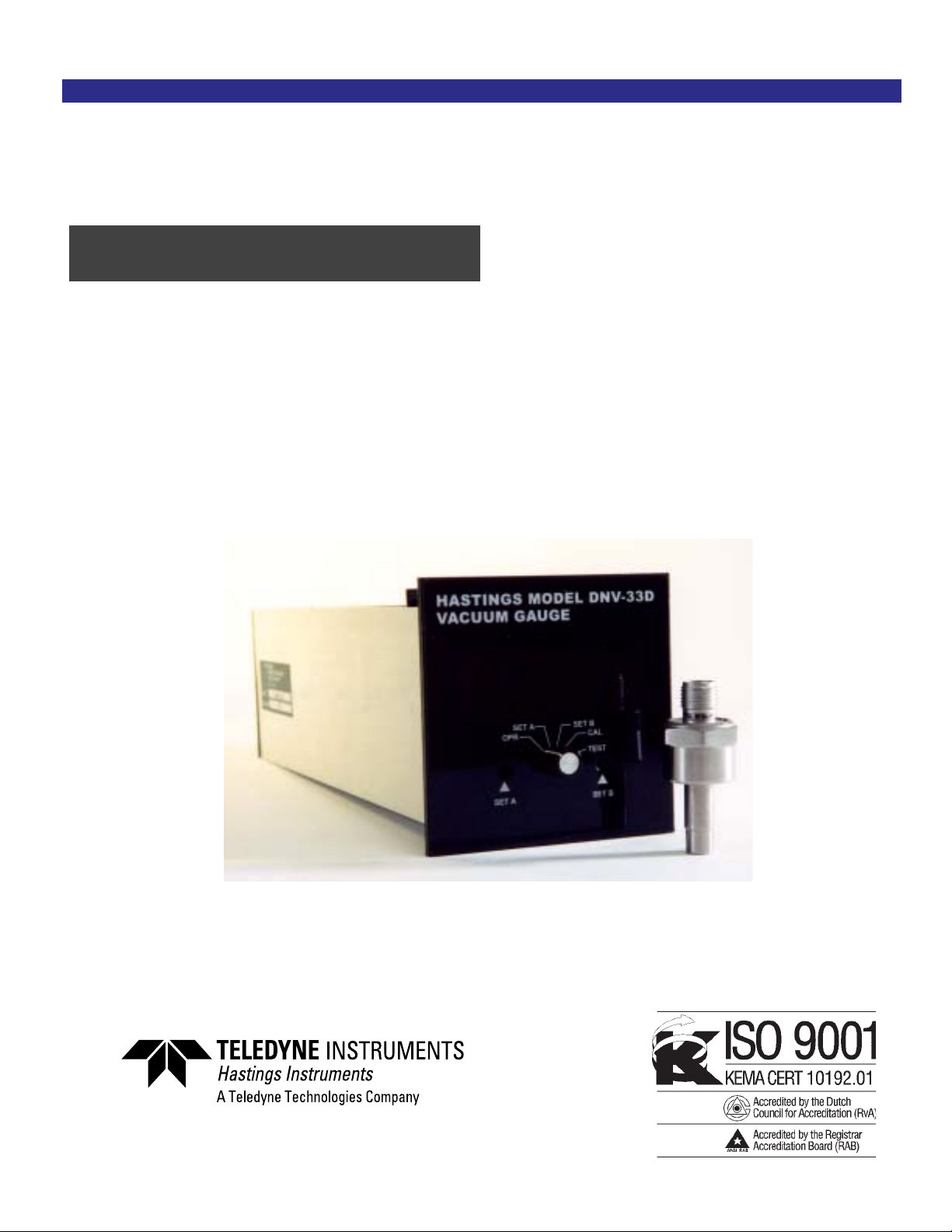
HASTINGS MODEL DNVHASTINGS MODEL DNV
HASTINGS MODEL DNV
HASTINGS MODEL DNVHASTINGS MODEL DNV
VV
AA
V
VV
CUUM GCUUM G
A
CUUM G
AA
CUUM GCUUM G
INSTRUMENTS
-33D-33D
-33D
-33D-33D
AA
UGEUGE
A
UGE
AA
UGEUGE
page 1
Page 2

Manual Print HistoryManual Print History
Manual Print History
Manual Print HistoryManual Print History
The print history shown below lists the printing dates of all revisions and addenda created for
this manual. The revision level letter increases alphabetically as the manual undergoes subsequent updates. Addenda, which are released between revisions, contain important change
information that the user should incorporate immediately into the manual. Addenda are numbered sequentially. When a new revision is created, all addenda associated with the previous
revision of the manual are incorporated into the new revision of the manual. Each new revision
includes a revised copy of this print history page.
Revision A (Document Number 156-122000).................................................... December 2000
Revision B (Document Number 156-082005)..........................................................August 2005
Visit www.teledyne-hi.com for WEEE disposal guidance.
page 2
Hastings Instruments reserves the right to change or modify the design of its equipment without
any obligation to provide notification of change or intent to change.
Page 3

TT
able of Contentsable of Contents
T
able of Contents
TT
able of Contentsable of Contents
II
GENERAL DESCRIPTIONGENERAL DESCRIPTION
I
GENERAL DESCRIPTION
II
GENERAL DESCRIPTIONGENERAL DESCRIPTION
IIII
OPERAOPERA
II
OPERA
IIII
OPERAOPERA
1.01.0
SPECIFICASPECIFICA
1.0
SPECIFICA
1.01.0
SPECIFICASPECIFICA
2.02.0
INSTINST
2.0
INST
2.02.0
INSTINST
2.1 Panel Mounting.................................................................................................................. 8
2.2 Gauge T ube Connections ................................................................................................... 8
2.3 Connection of Relay Contacts and Output T erminals ....................................................... 8
2.4 Gauge T ube Installation ..................................................................................................... 8
3.03.0
OPERAOPERA
3.0
OPERA
3.03.0
OPERAOPERA
3.1 Powering of Vacuum Gauge............................................................................................... 9
3.2 Switch Position................................................................................................................... 9
TION PRINCIPLETION PRINCIPLE
TION PRINCIPLE
TION PRINCIPLETION PRINCIPLE
TIONSTIONS
TIONS
TIONSTIONS
ALLAALLA
ALLA
ALLAALLA
TION PRTION PR
TION PR
TION PRTION PR
TION OF TION OF
TION OF
TION OF TION OF
......................................................................................................................................................................
...................................................................................
......................................................................................................................................................................
VV
AA
CUUM GACUUM GA
V
A
CUUM GA
VV
AA
CUUM GACUUM GA
..........................................................................................................................................
.....................................................................
..........................................................................................................................................
..............................................................................................................................................
.......................................................................
..............................................................................................................................................
OCEDUREOCEDURE
OCEDURE
OCEDUREOCEDURE
..........................................................................................................................
.............................................................
..........................................................................................................................
UGEUGE
............................................................................................................
UGE
......................................................
UGEUGE
............................................................................................................
55
5
55
77
7
77
77
7
77
88
8
88
99
9
99
4.04.0
CALIBRACALIBRA
4.0
CALIBRA
4.04.0
CALIBRACALIBRA
4.1 Check of Tube Accuracy .................................................................................................... 9
4.2 DNV-33 Calibration ........................................................................................................ 10
4.2.1 Reference Check .............................................................................................................. 10
4.2.2 Recalibration for Length Gauge Tube Cable.................................................................... 10
4.2.3 Optimizing Gauge Tube Accuracy................................................................................... 10
5.05.0
NONO
5.0
5.05.0
5.1 Effects of Condensable Vapors......................................................................................... 10
5.2 Outgassing........................................................................................................................ 11
5.3 Ingassing .......................................................................................................................... 11
5.4 Effect of Thermal Conductivity ...................................................................................... 11
5.5 Effect of System Conductance......................................................................................... 15
6.06.0
6.0
6.06.0
TES ON TES ON
NO
TES ON
NONO
TES ON TES ON
WW
ARRANTYARRANTY
W
ARRANTY
WW
ARRANTYARRANTY
TION TION
TION
TION TION
AND AND
AND
AND AND
VV
AA
CUUM MEASUREMENTCUUM MEASUREMENT
V
A
CUUM MEASUREMENT
VV
AA
CUUM MEASUREMENTCUUM MEASUREMENT
......................................................................................................................................................................................
...........................................................................................
......................................................................................................................................................................................
TRTR
OUBLESHOOOUBLESHOO
TR
OUBLESHOO
TRTR
OUBLESHOOOUBLESHOO
TING GUIDETING GUIDE
TING GUIDE
TING GUIDETING GUIDE
......................................................................................
...........................................
......................................................................................
1010
10
1010
1212
12
1212
99
9
99
page 3
Page 4

page 4
Page 5

SECTION I
General Description
The Hastings Digital Vacuum Gauge, Model DNV-33D, incorporates proven Hastings thermopile technology to produce a linear vacuum gauge that covers the range of 1-1000 mTorr. The
digital display reads directly in mTorr. The instrument provides an analog output signal which
may be used to drive a remote indicator for recording, data logging, etc. The output is scale is
1 volt for 1000 mTorr.
The DNV-33D also includes dual set points (A set and B set) with LED indicators located on
the front panel. Relay contacts are also provided for remote switching.
The rear panel of the instrument provides access to terminal blocks for AC power cord, gauge
tube, relays and analog output connections. The calibration adjustment potentiometers may also
be accessed through the back panelof the unit. The instrument is factory calibrated on a standard average curve for DNV-33 vacuum gauges.
page 5
Page 6

page 6
Page 7

The operation of Hastings vacuum gauges uses a patented noble metal thermopile circuit. The
hot junctions of the thermopile are heated directly by an AC current while an equal number of
cold junctions are kept at ambient temperature by heavy mounting studs. Thus a DC voltage is
then generated between the hot and cold junctions. As the pressure decreases, the lowering of
the thermal conductivity of the gas surrounding the hot junction tends to increase the temperature of the hot junctions, thus increasing the output of the thermopile. This change in output is
then amplified, linearized, and calibrated as a function of pressure.
1.0 SPECIFICATIONS
Indicator Model ....................................................................................................DNV-33D
Case Dimension.......................................................Front Panel 96mm SQ. Depth 10 ¾”
Gauge Tube Type ....................................................... DV-33D-1, DV-33D-2, DV-33D-3*
SECTION II
Operating Principle
Gauge Tube Shell ......................................................................Welded stainless steel shell
Overpressure.............................................................................................1500 PSIG max.
Panel Cut-out ................................................ 3-1/16” (77.5 mm) H x 3-5/8” (92mm)W
Range .............................................................................................................. 1-1000 mTorr
Readout........................................................................................................... Digital Meter
Power ....................................................................................... 115 VAC, less than 6 watts
Outputs ................................................................. Linear 0-1 VDC analog @ 4 ma. Max.
Calibration .............................................................................. Calibrated for air or nitrogen
*Dash number Defines System Fitting Differences:
-1 Weld Fitting
-2 Cajon #SS-4 VCR Male Gland
-3 Cajon #SS-4 VCR Female Gland
page 7
Page 8

2.0 INSTALLATION
QUICK START
Install DV-33D gauge tube in vacuum system (see section 2.4). Ensure system
is leak free.
Connect the tube to the DNV-33D power supply/display and apply 115 VAC.
Allow 30 minutes for warm-up (see section 3.1).
Set the switch on the DNV-33D to the “OPR” position for normal operation
(factory calibration).
Set the switch on the DNV-33D to the “Set A” position. The relay will now be
energized when the pressure is less than the set point. The set point LED will be
on when the relay is energized. The set point may be set by adjusting the appropriate potentiometer on the front panel.
Set the switch on the DNV-33D to the “Set B” position. The relay will now be
energized when the pressure is less than the set point. The set point LED will be
on when the relay is energized. The set point may be set by adjusting the appropriate potentiometer on the front panel.
Set the switch on the DNV-33D to the “CAL” position. This is to be used when
zeroing the gauge with the tube at a pressure less than 0.1 mTorr.
Set the switch on the DNV-33D to the “TEST” position. Use this position to
check the DNV-33D and to set the gain for individual tubes.
2.12.1
PP
anel Mountinganel Mounting
2.1
P
anel Mounting
2.12.1
PP
anel Mountinganel Mounting
The DNV-33D instrument package can be mounted in a 3-1/16 inch high by 3-5/8 inches wide
hole. Secure the gauge with the mounting brackets provided.
2.22.2
Connect the Gauge Connect the Gauge
2.2
Connect the Gauge
2.22.2
Connect the Gauge Connect the Gauge
REAR PANEL GAUGE TUBE WIRE COLOR
“TUBE” PIN #
A A BLACK
C C WHITE
D D GREEN
TT
ube wire to the gauge as folloube wire to the gauge as follo
T
ube wire to the gauge as follo
TT
ube wire to the gauge as folloube wire to the gauge as follo
ws:ws:
ws:
ws:ws:
page 8
2.32.3
Connect other wires to relaConnect other wires to rela
2.3
Connect other wires to rela
2.32.3
Connect other wires to relaConnect other wires to rela
2.42.4
Gauge Gauge
2.4
Gauge
2.42.4
Gauge Gauge
Install the gauge tube in a clean, dry vacuum system with the open end pointing down so as to
be self-draining should any vapors condense within the tube (See Sec. 5.1). For maximum
accuracy, it is recommended that the tube be outgassed in the vacuum system for a minimum of
4 hours.
TT
ube Installaube Installa
T
ube Installa
TT
ube Installaube Installa
tiontion
tion
tiontion
y contacts and output tery contacts and output ter
y contacts and output ter
y contacts and output tery contacts and output ter
minalsminals
minals
minalsminals
..
.
..
Page 9

3.0 OPERATION OF VACUUM GAUGE
3.13.1
PP
oo
ww
erer
o
oo
w
ww
ing of ing of
er
ing of
erer
ing of ing of
3.1
P
3.13.1
PP
Plug the 8 ft. power cable into a single phase 115 VAC (DNV-33D) or 230 VAC (ENDV33D)line. A line frequency of either 50 or 60 Hz is satisfactory. Allow 30-40 minutes for warmup.
Plug the gauge tube cable onto the gauge tube. When the tube is exposed to a pressure greater
than1000 mTorr, the analog output will be over 2 volts, and the display will read “1”.
The relay will energize when the pressure is below the trip points. “Normal” relay position is deenergized (ATM pressure side of set point.)
3.23.2
Switch PSwitch P
3.2
Switch P
3.23.2
Switch PSwitch P
“OPR” Normal operating position. Display reads pressure. Output on back panel reads 0-1
volt.
“SET A; SET B” Displa ys the trip point of the appropriate relay. If the pressure is below the trip
point the relay is energized and the LED will be lit. The trip points can be set from 0-950 mTorr.
The relay trip points are set by adjusting the appropriate pot located on the front panel.
“CAL” Used when zeroing the vacuum gauge tube at hard vacuum. Adjust the Cal pot on the
rear panel for 000 on the display.
“Test” A voltage is injected into the 2
the average curve. Adjust ‘GAIN’ pot on rear panel for “400” on the display. NOTE: The
signal output will change when the switch is put in this position and the set points may trip. See
section 4.2.1 Reference Check.
VV
acuum Gaugeacuum Gauge
V
acuum Gauge
VV
acuum Gaugeacuum Gauge
ositionosition
osition
ositionosition
nd
stage AMP so that the GAIN of the gauge can be set on
4.0 CALIBRA TION AND TROUBLESHOOTING GUIDE
All Hastings vacuum gauges and tubes have been carefully checked and calibrated at the factory
before shipment. If a calibration check is desired the methods in the following sections may
prove helpful.
4.14.1
Check of Check of
4.1
Check of
4.14.1
Check of Check of
The simplest and quickest method of checking the operation and calibration of power supply/
display and gauge tube is to keep a new, clean gauge tube on hand as a “standard”. To check
operation, install both of the gauge tubes together in the same clean, dry vacuum system, and
pump until a steady pressure is obtained. Plug the gauge onto both tubes alternately and check
reading. Be sure to allow time for readings to settle. If the tube reads a considerably higher
pressure than the tube being used as a standard, a calibration shift in the old tube has occured.
This is most likely resulting from tube contamination. The tube calibration can possibley be
restored by gently rinsing the interior of the tube with a solvent such as trichlorethylene. After
cleaning, thoroughly dry the tube and degas it before reinstallation into a vacuum system. This
is done to avoid system contamination by the solvent. If calibration cannot be restored by this
precedure, replace the old tube with a new gauge tube.
CAUTION: Do not attempt to measure the resistance of the gauge tube element while it is
under vacuum. Some ohmmeters apply measuring voltages sufficient to burn out the thermopile while under vacuum. The resistance of the gauge tube can be measured safely at atmospheric pressure. This measurement is made between pins 3, 5 and 7 counting clockwise from
the key looking at the base of the gauge tube. A measuring device such as the Triple Model 630
Test Set with ohms switch on the “X10” range, is suitable for this purpose.
TT
T
TT
ube ube
ube
ube ube
AccuracAccurac
Accurac
AccuracAccurac
yy
y
yy
page 9
Page 10

Warranty and Repair
4.24.2
DNVDNV
DNV
DNVDNV
-33 Calibra-33 Calibra
-33 Calibra
-33 Calibra-33 Calibra
4.2
4.24.2
All calibration voltages are factory set and will rarely change. The methods for checking gauge
calibration are detailed below:
tiontion
tion
tiontion
4.2.14.2.1
4.2.1
4.2.14.2.1
The DNV-33D incorporates a quick reference check reading. To utilize this feature the front
panel switch must be in the TEST position. In this position the digital display should read “400”
(+3). If it does not read this the calibration GAIN pot should be adjusted to bring the reading
back to “400”. This will bring the gauge back on the standard average calibration curve.
NOTE: The signal output will change when the switch is put in this position and the set points
may trip.
Pump the gauge tube down to hard vacuum. Set the front panel switch to the ‘CAL’ position.
Adjust the ‘CAL’ pot in the rear of the unit for 000 on the display. If there is a midscale reference available to the system, see section 4.2.3 on recalibration. Calibration is complete for use
with the standard average curve.
4.2.24.2.2
4.2.2
4.2.24.2.2
A maximum of 100 feet of gauge tube cable can be utilized by the DNV-33D. If the cable length
or size (18 gauge) is changed, the unit must be recalibrated. The procedure for recalibration is
described in section 4.2.1.
4.2.34.2.3
4.2.3
4.2.34.2.3
Individual tubes can be trimmed for best fit upscale on the curve by performing a calibration
adjustment of the gain pot vs. tube output against an accurate reference standard, to do this:
Reference CheckReference Check
Reference Check
Reference CheckReference Check
RecalibraRecalibra
Recalibra
RecalibraRecalibra
Optimizing Gauge Optimizing Gauge
Optimizing Gauge
Optimizing Gauge Optimizing Gauge
tion for Different Length Gauge tion for Different Length Gauge
tion for Different Length Gauge
tion for Different Length Gauge tion for Different Length Gauge
TT
T
TT
ube ube
ube
ube ube
AccuracAccurac
Accurac
AccuracAccurac
TT
ube Cablesube Cables
T
ube Cables
TT
ube Cablesube Cables
yy
y
yy
Pump the gauge tube down to hard vacuum. Set the front panel switch to the “CAL” position.
Adjust the “CAL” potentiometer in the rear of the unit until the display reads 000.
Pump the system to a known pressure using a reference in the system. At this pressure, adjust
the gain potentiometer until the display reading matches the reference reading. The unit should
now be calibrated. Best average fit to the curve will occur if 700 mTorr is used for this setting.
Do not use this instrument with another tube unless resetting the gain to “400” per 4.2.1 or
performing the above procedure for the specific tube.
5.0 Notes on Vacuum Measurements
5.1 Effects of Condensable 5.1 Effects of Condensable
5.1 Effects of Condensable
5.1 Effects of Condensable 5.1 Effects of Condensable
If the readings of Hastings gauges are to be compared with readings of other types of gauges,
consideration must be given to the possible effects of condensable vapors on other gauges. For
example, none of the many types of McLeod gauges, give correct readings if condensable
vapors such as water, alcohol, acetone, etc., are present in the gauge. The McLeod gauge
operates by compressing residual gases and vapors to obtain a reading, and this compression will
tend to compress vapors that are present. This usally results in pressure reading that is lower
than the actual pressure. Furthermore two different McLeod gauges could be used and both
may have different readings. Both of these readings however could be incorrect if vapors are
VV
V
VV
aporapor
apor
aporapor
ss
s
ss
page 10
Page 11

present. Hastings thermopile gauges however, have the useful property of responding to the
total pressure of all gases and vapors that are present in the gauge tube.
To exclude vapors from a vacuum system, it is necessary to employ a trap of some kind that will
absorb or condense vapors. Water vapor is by far the most common source of this difficulty. A
cold trap cooled by liquid nitrogen is an effective means in removing vapors.
It may be necessary to keep McLeod gauges constently under vacuum for several hours, or days
with a trap before it will read correctly. The use of rubber or Tygon tubing connecting the gauge
to the vacuum system can lead to gross errors due to excessive outgassing and or adsorbtion by
the tube. It is recommended that only glass or metal tubing be used. Reference should be made
to the instructions furnished by the manufacturer of the McLeod gauge to be sure that it is
provided with a suitable trap.
5.2 Outgassing5.2 Outgassing
5.2 Outgassing
5.2 Outgassing5.2 Outgassing
Hastings gauge tubes are fabricated from materials which have been proven by years of usage to
be relatively free from outgassing. However; all surfaces of glass and metal that are exposed to
the vacuum system may liberate gases and vapors that were previously adsorbed during exposure to the atmosphere. If the surfaces are contaminated with foreign matter, this outgassing
may be much more persistent than if the surfaces are clean. The possibility of outgassing must
be considered in checking the accuracy of Hastings gauges or in checking for leaks. This is
especially important when working with pressures of less than 10 mTorr where atmospheric
gases are likely to flood the enclosure due to leaks.
Also, if the system is being pumped continuously, gauges spaced at different distances from the
pump will register different pressures. For a reliable comparison of different vacuum gauges, it
is necessary then to insure that the vacuum system be free of any outgasses or other sources of
apparent leaks. This can best be determined by closing off the system from the pumps and
observing if there is any rise in pressure within the range of interest.
5.3 Ingassing5.3 Ingassing
5.3 Ingassing
5.3 Ingassing5.3 Ingassing
Ingassing is an effect opposite to outgassing and may also lead to erroneous readings. Ionization
gauges exhibit a kind of pumping action that tends to clean up residual gasses in certain ranges
of pressure and thereby lower the pressure. Also, if a cold trap is in a closed system, the total
pressure may change considerable while condenseble vapors such as water, carbon dioxide and
mercury and being condensed.
5.4 Effects of 5.4 Effects of
5.4 Effects of
5.4 Effects of 5.4 Effects of
All Hastings vacuum gauges are originally calibrated in dry air. Since this calibration is a
function of thermal conductivity, any gas having a thermal conductivity different from that of air
will also have a different calibration. Contact factory for calibration in gases other than air.
5.5 Effects of System Conductance5.5 Effects of System Conductance
5.5 Effects of System Conductance
5.5 Effects of System Conductance5.5 Effects of System Conductance
Each element that makes up a vacuum system has associated with it a certain conductance (that
is the opposite of resistance). For example, baffles, connecting tubing, and sharp turns may
cause pressure drops throughout the system during pumping and during the time in which the
system is reaching static equilibrium. It is not an uncommen occurence to measure different
pressures at different locations in a vacuum system. In checking the calibration of a vacuum
gauge, care must be taken to insure that the gauge and the reference are at the same pressure.
TherTher
mal Conductivitymal Conductivity
Ther
mal Conductivity
TherTher
mal Conductivitymal Conductivity
page 11
Page 12

SECTION 6
Warranty
6.1 Warranty Repair Policy
Hastings Instruments warrants this product for a period of one year from the date of shipment to be free
from defects in material and workmanship. This warranty does not apply to defects or failures resulting
from unauthorized modification, misuse or mishandling of the product. This warranty does not apply to
batteries or other expendable parts, nor to damage caused by leaking batteries or any similar occurrence.
This warranty does not apply to any instrument which has had a tamper seal removed or broken.
This warranty is in lieu of all other warranties, expressed or implied, including any implied warranty as to
fitness for a particular use. Hastings Instruments shall not be liable for any indirect or consequential
damages.
Hastings Instruments, will, at its option, repair, replace or refund the selling price of the product if
Hastings Instruments determines, in good faith, that it is defective in materials or workmanship during the
warranty period. Defective instruments should be returned to Hastings Instruments,
together with a written statement of the problem and a Return Material Authorization (RMA) number.
Please consult the factory for your RMA number before returning any product for repair. Collect freight
will not be accepted.
shipment prepaid,
.2 Non-Warranty Repair Policy
Any product returned for a non-warranty repair must be accompanied by a purchase order, RMA form
and a written description of the problem with the instr ument. If the repair cost is higher, you will be
contacted for authorization before we proceed with any repairs. If you then choose not to have the
product repaired, a minimum will be charged to cover the processing and inspection. Please consult the
factory for your RMA number before returning any product repair.
TELEDYNE HASTINGS INSTRUMENTS
804 NEWCOMBE AVENUE
HAMPTON, VIRGINIA 23669 U.S.A.
ATTENTION: REPAIR DEPARTMENT
TELEPHONE (757) 723-6531
1-800-950-2468
FAX (757) 723-3925
E MAIL hastings_instruments@teledyne.com
INTERNET ADDRESS http://www.teledyne-hi.com/
page 12
Repair Forms may be obtained from the “Information Request” section of the
Hastings Instruments web site.
 Loading...