

Teledyne Deltaflow DF180 Operation And Maintenance Manual

DF180 GAS FLOW AND TEMPERATURE MONITOR
Operation and Maintenance Manual
Teledyne Monitor Labs
35 Inverness Drive East
Englewood, CO 80112
TML DOCUMENT 99702200
Revision A
www.teledyne-ml.com

This document contains information proprietary to Teledyne Monitor Labs and is furnished with the
Transfer of EAR99 technical
express condition that the information contained herein will not be used for second source procurement
or directly or indirectly in any way detrimental to the interests of Teledyne Monitor Labs.
information
Use and Disclosure of Data
Information contained herein is classified as EAR99 under the U.S. Export
Administration Regulations. Export, reexport or diversion contrary to U.S. law
is prohibited.
Please contact your local Teledyne Monitor Labs regional sales or service representative, or call our
home office, if you require assistance.
Sales 800-422-1499
Technical Support 800-846-6062
Parts 800-934-2319
January, 2018 Page 2

Table of Contents
Table of Contents .......................................................................................................................................... 3
Specifications ................................................................................................................................................ 6
1 System Description ............................................................................................................................... 7
1.1 Instrument Panel ........................................................................................................................... 7
1.1.1 Controller .............................................................................................................................. 7
1.1.2 Differential Pressure (DP) Transmitter.................................................................................. 9
1.1.3 Push Buttons ......................................................................................................................... 9
1.1.4 Valve Manifold Assembly ...................................................................................................... 9
1.1.5 Absolute Pressure Transmitter ........................................................................................... 10
1.1.6 Temperature Transmitter ................................................................................................... 10
1.1.7 Precision Differential Pressure Switch ................................................................................ 11
1.1.8 Sample Filters ...................................................................................................................... 12
1.1.9 Power Supplies .................................................................................................................... 12
1.1.10 Precision Regulator ............................................................................................................. 12
1.2 Probe ........................................................................................................................................... 13
1.3 Sample Line ................................................................................................................................. 13
2 Theory of Operation ............................................................................................................................ 14
3 Installation .......................................................................................................................................... 16
3.1 Pre-Installation Planning and Preparation .................................................................................. 16
3.2 Site Selection ............................................................................................................................... 16
3.2.1 Representative Sampling Location ...................................................................................... 16
3.2.2 Access to Sampling Location ............................................................................................... 16
3.2.3 Environmental Conditions at Instrument Panel Location ................................................... 17
4 Web Interface ..................................................................................................................................... 17
4.1 Data ............................................................................................................................................. 19
4.1.1 Data: Values ........................................................................................................................ 19
4.1.2 Data: Alarms ........................................................................................................................ 20
4.1.3 Data: Calibrations ................................................................................................................ 20
4.1.4 Data: Modbus Map ............................................................................................................. 20
January, 2018 Page 3

4.1.5 Data: Tools .......................................................................................................................... 21
4.2 Control ........................................................................................................................................ 22
4.3 Configuration .............................................................................................................................. 23
4.3.1 Configuration: General ........................................................................................................ 23
4.3.2 Configuration: Inputs .......................................................................................................... 24
4.3.2.1 Configuration: Inputs: Analog ......................................................................................... 24
4.3.2.2 Configuration: Inputs: Modbus ....................................................................................... 25
4.3.2.3 Configuration: Inputs: Digital .......................................................................................... 25
4.3.2.4 Configuration: Inputs: Temperature ............................................................................... 25
4.3.3 Configuration: Outputs ....................................................................................................... 25
4.3.3.1 Configuration: Outputs: Computed ................................................................................ 25
4.3.3.1.1 Configuration: Outputs: Computed: Raw Velocity ................................................... 25
4.3.3.1.2 Configuration: Outputs: Computed: Velocity ........................................................... 25
4.3.3.1.3 Configuration: Outputs: Computed: Actual Volumetric Flow................................... 26
4.3.3.1.4 Configuration: Outputs: Computed: Standard Volumetric Flow .............................. 26
4.3.3.2 Configuration: Outputs: Analog ...................................................................................... 27
4.3.4 Configuration: Calibrations ................................................................................................. 27
4.3.4.1 Configuration: Calibrations: Timing ................................................................................ 27
4.3.4.2 Configuration: Calibrations: Evaluations ......................................................................... 28
4.4 Administrator .............................................................................................................................. 29
5 Operation ............................................................................................................................................ 29
5.1 Calibration and Adjustment ........................................................................................................ 29
5.2 Interference Check ...................................................................................................................... 30
5.3 Creating a Correction Curve ........................................................................................................ 30
5.4 Long-Term Shutdown .................................................................................................................. 31
6 Maintenance ....................................................................................................................................... 32
6.1 Scheduled Preventative Maintenance Chart .............................................................................. 32
6.2 Pitot Tube Cleaning Procedure ................................................................................................... 32
6.3 Sample Line Cleaning Procedure ................................................................................................ 32
6.4 Filter Media Replacement Procedure ......................................................................................... 33
January, 2018 Page 4

6.5 System Leak Test Procedure ....................................................................................................... 33
7 Troubleshooting .................................................................................................................................. 34
Appendix A: Spare Parts .............................................................................................................................. 35
Appendix B: Drawings ................................................................................................................................. 36
January, 2018 Page 5

Specifications
Flow Measurement:
Range:
0-300ft/sec (0-91m/sec)
Long-Term Repeatability:
+/-0.3ft/sec (+/-0.1 m/sec)
Relative Accuracy:
(vs. EPA Test Method 2)
Site dependent, see Commercial Performance
Warranty. Typically <5% above 10 ft/sec
Response Time:
8 sec
Drift:
+/- 1.5% of span over operating temperature range of instrument panel
Media Conditions:
Temperature:
-40° to 1000°F (-40° to +343°C)
Pressure:
-2 to 2 psig (-13.8 to 13.8 kPa)
Moisture:
Dry to saturated, including condensed water
Particulate:
</=3000 mg/m3
Duct Size:
Diameter:
From 3 - 45 Ft. (0.9 – 14m) Dia.
Temperature
Measurement:
Accuracy:
+/- 6 °F (3.3°C)
Long-Term Repeatability:
+/- 0.5% of span per year
Power:
100-240 VAC, 50/60Hz, Single Phase, 70 VA Maximum
Environment:
Ambient Temp. Limits:
Probe Assembly: -40°F to +160°F (-40° to 71°C)
Instrument Enclosure: +20°F to 104°F (-7°C to +40°C)
Relative Humidity:
Probe Assembly: 5% to 100% humidity, condensing
Instrument Enclosure: 0 to 95% non-condensing
Instrument Enclosure
NEMA 4/IP66 is standard, Ex Py purge protection can be
Mounting:
Process Connection:
4” 150# ANSI flange
Sizes & Weights:
Instrument Enclosure
Size: 30H x 24W x 12D (inches)
Weight: 135 lbs. (61 kg)
Probe Assembly
Size: Application dependent
Weight: 26 lbs. (11.8 kg), typical, application dependent
I/O:
Communication Protocol:
Modbus TCP/IP
Analog Outputs:
Two Outputs, 4-20mA current, one for differential pressure
Digital Inputs:
4 Inputs, dry contact Inputs are configurable to initiate
Relay Outputs:
Four configurable Outputs, Form C, (Single Pole Double
Maximum Contact Current: 10 Amps AC
Ratings:
January, 2018 Page 6
added as an option for Class I Division 2, and Zone 2
applications.
76H x 61W x 30.5D (cm)
and one for temperature
blow back, calibrations, Unit On, etc.
Throw)
Contact Voltage: 120/240VAC
1 System Description
The DeltaFlow 180 is an EPA compliant Pitot tube based flow monitoring system. The three main
components of the system are the instrument panel, probe, and sample line. This section describes in
detail each of these components.
1.1 Instrument Panel
The Instrument panel is typically mounted in a climate controlled area, and can be provided with or
without an enclosure. All the electronics, indicators, and valves for the system are located here.
Fig. 1-1 Deltaflow Instrument Panel
1.1.1 Controller
Daily quality assurance checks, signal processing, and monitor configuration are all handled by the
controller. The controller module I/O consists of 8 relays and 8 digital inputs. The relays are used to
control solenoid valves located on the instrument panel during calibration checks, interference checks,
and blowback sequences. The digital inputs are used to initiate different modes such calibration,
interference check, blowback, and maintenance. These modes can be initiated by the buttons located
on the instrument panel or by external dry contact signals from a plant distributed control system (DCS)
that are wired to the Deltaflow instrument panel terminal blocks.
Fig. 1-2 Deltaflow Controller, Analog Module, and Form C Relay Module
January, 2018 Page 7

The controller has two external modules, the analog module and the form C relay module. The analog
Main Controller Module
Channel
Description
Relay 1
Solenoid Valve 1 – Impact Line Purge
Relay 2
Solenoid Valve 2 – Static Line Purge
Relay 3
Solenoid Valve 3 – Isolate DP Transmitter Low Side
Relay 4
Solenoid Valve 4 – Isolate DP Transmitter High Side
Relay 5
Solenoid Valve 5 – Span Calibration
Relay 6
Solenoid Valve 6 – Span Calibration (Low Pressure Instrument Air Delivery)
Relay 7
Solenoid Valve 7 – Span Calibration (Isolate DP Pressure Switch)
Relay 8
Not Used
Digital input 1
External Calibration Start
Digital input 2
External Interference Check Start
Digital input 3
External Blowback Start
Digital input 4
Maintenance
Digital input 5
Calibration Start
Digital input 6
Interference Check Start
Digital input 7
Blowback Start
Digital input 8
Not Used
Analog Module
Input 1
Differential Pressure
Input 2
Stack Temperature
Input 3
Stack Pressure
Input4
User defined
Output 1
Configurable – Differential Pressure, Stack Temperature, Stack Pressure, Velocity, Raw
Output 2
Configurable – Differential Pressure, Stack Temperature, Stack Pressure, Velocity, Raw
Form C Relay
Relay 1
In Calibration Mode
Relay 2
In Sample Mode
Relay 3
CEMS Fault (reverse logic, 1 = OK: 0 = Fault)
Relay 4
Value Based Alarm (e.g. based on user defined alarm limits)
module is used to take in 4-20mA signals from the various sensors on the instrument panel, and
transmit analog signals out of the instrument panel, such as velocity and temperature. The form C relay
module is used to relay status signals, such as fault or sample valid. Terminated on the form C relay
module is a temperature sensor that measures the ambient temperature of the instrument panel. Table
1-1 shows a complete I/O list for all the modules.
Table 1-1. Deltaflow Controller I/O list
Velocity, Actual Volumetric Flow, Standard Volumetric Flow, any user defined parameter
Velocity, Actual Volumetric Flow, Standard Volumetric Flow, any user define parameter
January, 2018 Page 8
1.1.2 Differential Pressure (DP) Transmitter
This device converts the pneumatic differential pressure signal measured by the probe to a 4-20mA
signal. It also provides a gauge style display to aid in troubleshooting the electrical signal. The gauge
needle can be zeroed and the 4-20mA signal can be calibrated at the display. Various ranges are
available; a TML Engineer selects the range based on process parameters of the application. See
Appendix A: Spare Parts for a complete list of all available ranges.
Fig. 1-3 Differential Pressure Transmitter with Display
1.1.3 Push Buttons
These buttons allow the user to start a blowback sequence, calibration check, interference check, or put
the Deltaflow into maintenance mode. Once pressed, the blowback sequence will start immediately.
Calibration and interference checks will start at the top of the next minute according to the controller
clock. Once pressed, the maintenance button will illuminate red and will put the Deltaflow into
maintenance mode until the button is pressed again. Maintenance mode causes the Deltaflow
controller to flag its’ data as invalid.
1.1.4 Valve Manifold Assembly
This assembly consists of 7 solenoid valves installed on a custom designed manifold. Static pressure,
impact pressure, and instrument air are directed through the manifold by the valves.
During normal sampling mode none of the valves are actuated; impact pressure and static pressure are
directed to the high and low sides of the differential pressure transducer, respectively. During a
blowback sequence or interference check, SV1 and SV2 send high pressure instrument air up the sample
line, while SV3 and SV4 isolate the differential pressure transmitter from the high pressure instrument
air.
The calibration check consists of a zero and span check. First, the DP transmitter high and low sides are
exposed to ambient pressure using SV3 and SV4. This provides a zero check. For the span check SV5,
SV6, and SV7 are activated. This allows low pressure instrument air to start pressurizing the DP
transmitter as well as the DP span set point switch. Once the DP span set point switch senses the correct
upscale pressure has been reached, it trips and shuts off SV6. This provides a stable upscale calibration
check. See the Plumbing & Instrumentation Diagram and the Timing Diagram in Appendix B for further
detail.
January, 2018 Page 9

Fig. 1-4 Solenoid Valve Manifold
1.1.5 Absolute Pressure Transmitter
Absolute stack pressure is needed to calculated velocity and standard volumetric flow. The DP
transmitter cannot continually measure stack pressure on its own. For this reason, the Deltaflow comes
standard with a 0-30 psia (61.1 inHg, 1551 mmHg) pressure transmitter. The transmitter is plumbed to
the static pressure line, and wired to input 3 of the analog module.
Fig. 1-5 Absolute Pressure Transmitter
1.1.6 Temperature Transmitter
Stack temperature is needed to calculated stack velocity and standard volumetric flow. The probe is
equipped with a type K thermocouple to accurately measure stack temperature. The thermocouple
signal is carried down to the instrument panel via thermocouple messenger cable in the sample line
where it is terminated on a DIN rail mounted transmitter. This device converts the thermocouple signal
to a 4-20mA signal that is wired to input 2 of the analog module.
The 4-20mA output range, and input type (RTD, TC, etc.) of the transmitter is adjustable using ProSense
XT-SOFT
software and a USB adapter cable (TML P/N 55000048-2).
January, 2018 Page 10

Fig. 1-6 Stack Temperature Transmitter
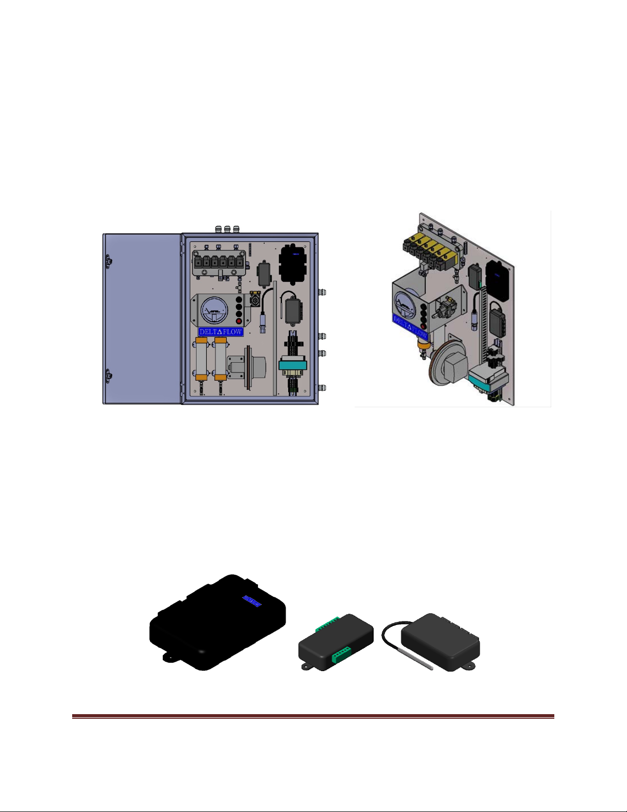
1.1.7 Precision Differential Pressure Switch
In order to provide a repeatable upscale differential pressure for daily calibration checks, a precision DP
switch is tied into the high side of the DP transmitter plumbing. During the beginning of a span check
this DP switch will shut off SV6 when it senses the correct pressure has been achieved on the high side
of the DP transmitter. This provides a repeatable and stable differential pressure to check the pneumatic
and electrical drift of the DP transmitter. The DP switch set point is adjustable via a screw at the left end
of the switch spring housing. These switches come in various ranges, see Appendix B: Spare Parts for a
complete list of all the available ranges.
Fig. 1-7 Precision Differential Pressure Switch
January, 2018 Page 11

1.1.8 Sample Filters
The differential pressure transmitter used in the Deltaflow is meant to only come in contact with clean
non- corrosive air. The Deltaflow purges the sample lines at a minimum of every 6 hours to ensure they
stay filled with clean instrument air. As added protection, each side of the DP transmitter has sample
filters that contain 13X molecular sieve, soda lime, and indicating Drierite®.
Fig. 1-7 Sample Filter
1.1.9 Power Supplies
Two power supplies are used. A 120W 24VDC power supply powers all the onboard Deltaflow
electronics, valves, and switches. A 10W 12 VDC power supply is used as loop power for the analog
outputs. Both power supplies’ inputs are rated 100-240VAC, 50/60Hz and are automatically adapting.
Both power supplies have “DC Voltage OK” indicating LEDs to aid in troubleshooting. The 24 VDC power
supply has a DC voltage output adjustment potentiometer.
1.1.10 Precision Regulator
In order to minimize the drift of the upscale differential pressure used during the daily cal checks, a
precision regulator is used that drops the instrument air supplied by the user from 50 psi down to 1.5
psi. This low pressure instrument air is bled into the high side plumbing of the DP transmitter by SV6 at
the beginning the of the daily upscale cal check.
Fig 1-8 Precision Regulator
January, 2018 Page 12
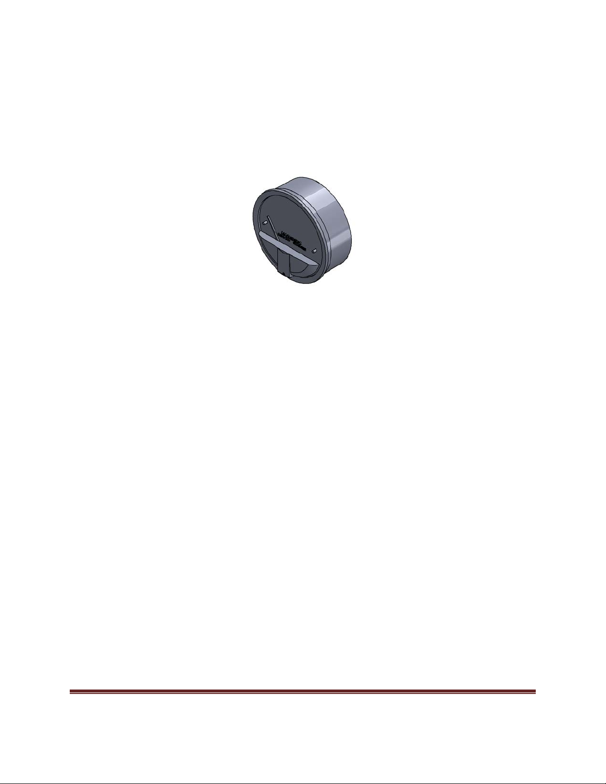
1.2 Probe
The Deltaflow Pitot tube probe assembly consists of an S type Pitot tube, a K type thermocouple, and a
4” mounting flange. All wetted components are constructed of Stainless steel. The Pitot tube comes in
various lengths, and the insertion depth is adjustable for easy installation. Once the desired insertion
depth is determined the Pitot tube is secured in place using a large compression fitting. The impact and
static sample lines are easily terminated on the probe using 3/8” compression fittings. The K type
thermocouple comes in various lengths and has a fixed insertion depth. The thermocouple wires from
the sample line are easily terminate in the head of the thermocouple assembly.
Figure 1-8 Deltaflow Probe
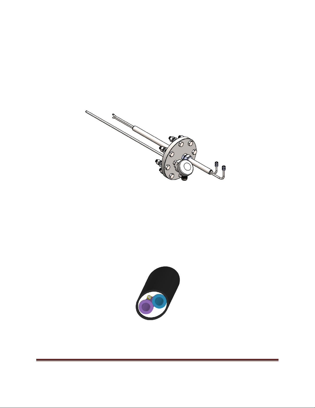
1.3 Sample Line
The Deltaflow sample line consists of a two 3/8” PFA Teflon sample lines, a K type thermocouple
messenger cable, a small amount of insulation, and a PVC jacket. The maximum recommended length
for the standard sample line is 430 feet. Line longer that this will require custom design. Custom sample
lines can be ordered with options such as stainless steel tubes, heaters, larger wires, or extra wires.
Fig. 1-9 Sample Line Cut Away
January, 2018 Page 13
 Loading...