

Teledyne DALSA Piranha PC-30-02K80-00-R, DALSA Piranha PC-30-02K60-00-R, DALSA Piranha PC-30-04K80-00-R, DALSA Piranha PC-30-04K60-00-R User Manual
Piranha Color Camera 1
Camera User’s Manual 03-032-10211-08 3-Jun-11
Piranha Color
Trilinear Camera
PC-30-02K80-00-R
PC-30-02K60-00-R
PC-30-04K80-00-R
PC-30-04K60-00-R

Piranha Color Camera 2
North America
605 McMurray Rd
Waterloo, ON N2V 2E9
Canada
Tel: 519 886 6000
Fax: 519 886 8023
www.teledynedalsa.com
sales.americas@teledynedalsa.com
support@teledynedalsa.com
Europe
Breslauer Str. 34
D-82194 Gröbenzell (Munich)
Germany
Tel: +49 - 8142 – 46770
Fax: +49 - 8142 – 467746
www.teledynedalsa.com
sales.europe@teledynedalsa.com
support@teledynedalsa.com
Asia Pacific
Ikebukuro East 13F
3-4-3 Higashi-Ikebukuro
Toshima-ku, Tokyo 170-0013
Japan
Tel: 81 3 5960 6353
Fax: 81 3 5960 6354 (fax)
www.teledynedalsa.com
sales.asia@teledynedalsa.com
support@teledynedalsa.com
© 2011 Teledyne DALSA. All information provided in this manual is believed to be
accurate and reliable. No responsibility is assumed by Teledyne DALSA for its use.
Teledyne DALSA reserves the right to make changes to this information without notice.
Reproduction of this manual in whole or in part, by any means, is prohibited without
prior permission having been obtained from Teledyne DALSA.
About Teledyne Technologies and Teledyne DALSA, Inc.
Teledyne Technologies is a leading provider of sophisticated electronic subsystems,
instrumentation and communication products, engineered systems, aerospace engines,
and energy and power generation systems. Teledyne Technologies’ operations are
primarily located in the United States, the United Kingdom and Mexico. For more
information, visit Teledyne Technologies’ website at www.teledyne.com.
Teledyne DALSA, a Teledyne Technologies company, is an international leader in high
performance digital imaging and semiconductors with approximately 1,000 employees
worldwide, headquartered in Waterloo, Ontario, Canada. Established in 1980, the
company designs, develops, manufactures and markets digital imaging products and
solutions, in addition to providing MEMS products and services. For more information,
visit Teledyne DALSA’s website at www.teledynedalsa.com.
Support
For further information not included in this manual, or for information on Teledyne
DALSA’s extensive line of image sensing products, please contact:

Piranha Color Camera 3
Contents
Features and Specifications 5
1.0 Introduction 5
1.1 Camera Performance Specifications 5
1.2 Image Sensor 11
1.3 Responsivity 12
Hardware Interface: Connectors and Timing 13
2.1 Installation Overview 13
2.2 Input/Output Connectors and LED 13
2.3 Camera LED 14
2.4 Power Connector 14
2.5 Camera Link Data Connector 15
2.6 Camera Timing 15
Software Interface: Configuring the Camera 21
3.1 First Power Up Camera Settings 21
3.2 Rebooting the Camera 22
3.3 Baud Rate 22
3.4 Select Cable 22
3.5 Help 22
3.6 Sensor Output 24
3.7 Data Output 26
3.8 Set Color Correction 27
3.9 Camera Selection Variables 28
3.10 Exposure Control 29
3.11 Spatial Correction 33
3.12 Averaging Horizontal Pixels 35
3.13 Processing Chain Overview and Description 36
3.14 Analog Gain and Analog Offset 38
3.15 Flat Field Correction 41
3.16 Digital Gain and Background Subtract 48
3.17 Look-Up Tables 49
3.18 Saving, Loading and Restoring Settings 51
3.19 Diagnostics 57
Optical and Mechanical Considerations 69
4.1 Mechanical Interface 69
4.2 Lens Mounts 70
4.3 Optical Interface 71
CCD Handling Instructions 73
5.1 Electrostatic Discharge and the CCD Sensor 73
5.2 Protecting Against Dust, Oil and Scratches 73
5.3 Cleaning the Sensor Window 74
Troubleshooting 75
6.1 Common Issues 75

Piranha Color Camera 4
Appendix A: ASCII Command Reference 79
Appendix B: Blue Correction Command 89
Appendix C: EMC Declaration of Conformity 91
Appendix D: Revision History 93
Index 95

Piranha Color Camera 5
Model Number
Description
PC-30-02k60-00-R
2k resolution, 3 taps at 60 MHz
PC-30-02k80-00-R
2k resolution, 3 taps at 80 MHz
PC-30-04k60-00-R
4k resolution, 3 taps at 60 MHz
PC-30-04k80-00-R
4k resolution, 3 taps at 80 MHz
Sensor Features
Value
Imager Format
Trilinear CCD
Resolution
2048 pixels
Features and Specifications
1.0 Introduction
Camera Features
2048 or 4096 trilinear RGB line scan sensor.
Color spacing: 3 lines, center-to-center.
Forward and reverse scanning operation.
Maximum line rates of 22 kHz (2k60) and 32 kHz (2k80), or 12 kHz (4k60) and 17
kHz (4k80).
Programmable analog gain and offset.
FPN and PRNU correction.
White balancing algorithms.
Optional luminance output.
Spatial correction.
Anti-blooming.
Configurable base or medium Camera Link.
RoHS and CE compliant.
Applications
100% print inspection.
Electronics manufacturing inspection.
Postal and parcel sorting.
High performance document scanning and image lift.
Narrow and large web inspection.
High-end industrial inspection.
Models
1.1 Camera Performance Specifications
2k Model Performance Specifications
Test conditions and notes follow. All numbers measured at 12-bit unless specified
otherwise.

Piranha Color Camera 6
Sensor Features
Value
Pixel Fill Factor
100%
Pixel Size
14 x 14 µm
Antiblooming
10x
Operating Ranges
Value
Minimum Line Rate
3.0 kHz (Operable to 1 Hz from external)
Maximum Line Rate
22.7 kHz (2k60) or 32.3 kHz (2k80)
Pixel RGB Throughput
Up to 80 Mps
Gain
-10 dB to +10 dB
Optical Interface
Value
Back Focal Distance
M72 Mount
19.56 mm (M72 x 0.75)
Sensor Alignment
x
y
z
z
± 50 µm
± 50 µm
± 250 µm
±0.2°
Lens Mount
M72 x 0.75, M42x1 and F-mount.
Mechanical Interface
Value
Camera Size
67 x 105 x 76 (l x h x w)
Mass
450 g
Power connector
Single voltage input (+12V to +15V) Hirose 6-pin circular male
Data connector
Camera Link MDR26F
Electrical Interface
Input Voltage
+12 to +15 volts
Power Dissipation
12 W
Operating Temperature (front
plate)
0 to 50 °C
Data Output Format
8 or 12 bits
Output Data Configuration
3 taps 8 bit
3 taps 12 bit
6 taps 8 bit

Piranha Color Camera 7
Operating Specifications
FFC
Unit
Color -10dB
0dB
+10dB
Min
Typ
Max
Min
Typ
Max
Min
Typ
Max
Responsivity
Off
DN/(nJ/cm²)
R
76 228
240
252 758 G 127 380
400
420 1264
B
63 190
200
210 632 Responsivity
On
DN/(nJ/cm²)
R
95 285
300
315 948
G 158 475
500
525 1580
B 79 238
250
263 790 Dynamic Range
On
Ratio
RGB
758
240
76 Random Noise
On
DN rms
RGB
5.4
10 17
30 54
95
DC Offset
DN RGB
180
180
180 FPN
Off
DN p-p
K60
RGB
25
55
137 K80
RG
K80
B*
60
140
450
FPN
On
DN p-p
RGB
10
PRNU global
Off
DN p-p
RGB
760
760
1000
PRNU pixel-to-pixel
Off
DN p-p
RGB
517
517
890
PRNU global
On
DN p-p
RGB
18
NEE
On
pJ/cm²
R
56.7
56.7
56.7 G 34
34
34 B 68
68
68 SEE
On
nJ/cm²
R
43.1
13.7
4.3 G 25.9
8.2
2.6 B 51.8
16.4
5.2
Saturation Output
Amplitude
DN RGB
4095
4095
4095
2k Model Operating Specifications
Test conditions and notes follow. All numbers measured at 12-bit unless specified
otherwise.

Piranha Color Camera 8
Sensor Features
Value
Imager Format
Trilinear CCD
Resolution
4096 pixels
Pixel Fill Factor
100%
Pixel Size
10 x 10 µm
Antiblooming
100x
Operating Ranges
Value
Minimum Line Rate
3.0 kHz (Operable to 1 Hz)
Maximum Line Rate
12.1 kHz (4k60) or 17.6 kHz (4k80)
Pixel RGB Throughput
up to 80 Mps
Gain
-10 dB to +10 dB
Optical Interface
Value
Back Focal Distance
M72 Mount
91.56 mm (M72 x 0.75)
Sensor Alignment
x
y
z
z
±50 µm
±50 µm
±250 µm
±0.2°
Lens Mount
M72 x 0.75, M42x1 and F-mount.
Mechanical Interface
Value
Camera Size
67 x 105 x 76 mm (l x h x w)
Mass
450 g
Power connector
Single voltage input (+12V to +15V) Hirose 6-pin circular male
Data connector
Camera Link MDR26F
Electrical Interface
Input Voltage
+12 to +15 volts
Power Dissipation
12 W
Operating Temperature
(front plate)
0 to 50 °C
Data Output Format
8 or 12 bits
Output Data
Configuration
3 taps 8 bit
3 taps 12 bit
6 taps 8 bit
4k Model Performance Specifications
Test conditions and notes follow. All numbers 12 bit unless specified otherwise.

Piranha Color Camera 9
Operating Specifications
FFC
Unit
Color
-10dB
0dB
+10dB
Min
Typ
Max
Min
Typ
Max
Min
Typ
Max
Responsivity
Off
DN/(nJ/cm²)
R
38 114
120
126 379 G 63 190
200
210 632 B 32 95
100
105 316 Responsivity
On
DN/(nJ/cm²)
R
47 143
150
158 474
G 79 238
250
263 790
B 40 119
125
131 395 Dynamic Range
On
Ratio
RGB
758
240
76 Random Noise
On
DN rms
RGB
5.4
10 17
30 54
95
DC Offset
DN RGB
180
180
180 FPN
Off
DN p-p
K60
RGB
40
87
275 K80
RG
K80
B*
60
140
450
FPN
On
DN p-p
RGB
10
PRNU global
Off
DN p-p
RGB
760
760
1000
PRNU pixel-to-pixel
Off
DN p-p
RGB
517
517
890
PRNU global
On
DN p-p
RGB
18
NEE
On
pJ/cm²
R
113.3
113.3
113.3
G
68
68
68 B 136
136
136 SEE
On
nJ/cm²
R
86
27.3
8.6 G 51.8
16.4
5.2 B 103.5
32.8
10.4
Saturation Output
Amplitude
DN RGB
4095
4095
4095
4k Model Operating Specifications
Test conditions and notes follow. All numbers measured at 12-bit unless specified
otherwise.

Piranha Color Camera 10
2K
4K
R G B R G B
-10 dB
800
480
960
1600
960
1920
0 dB
253
152
304
506
304
607
+10 dB
80
48
96
160
96
192
Specification tables test conditions and notes 2k and 4k models:
Line Rate: 400 Hz.
Exposure Time (µs):
Light Source: Broadband Quartz Halogen, BG-38, with 750nm cutoff filter
installed, Correction Color Temperature = 5300°K.
Ambient Test Temperature: 25°C.
Output swing (FFC off): 3220 DN includes 180 DN Dark Offset. (Range of 0 to
4095 DN).
Output swing (FFC on): 3800 DN.
All numbers are 12-bit unless specified otherwise.
The responsivity of each color is adjusted to achieve equal output.
Tested in Camera Link Mode clm 16.
PRNU specified at 75% of full swing.
General Notes:
Specifications apply to both 60 MHz and the 80 MHz camera models unless
indicated otherwise.
Specification with "FFC on" apply to the factory calibrated FFC. User calibrated
FFC may have a different affect on camera performance.
*FPN Notes:
2K80 cameras have increased FPN on the blue outputs between pixels 533 - 543
and 1506 - 1516.
4K80 cameras have increased FPN on the blue outputs between pixels 1045 - 1055
and 3042 - 3052.
Outside of this range, FPN meets the same specification as the other colors.
Piranha Color Camera 11
Red Tap 2
Red Tap 1
Blue Tap 2
Blue Tap 1
2048 or 4096 pixels
Red Tap 4
Red Tap 3
Green Tap 2
Green Tap 1
Green Tap 4
Green Tap 3
Red Tap 2
Red Tap
1
Blue Tap
1
Green Tap 2
Green Tap
1
30 µm (4k)
42 µm (2k)
30 µm (4k)
42 µm (2k)
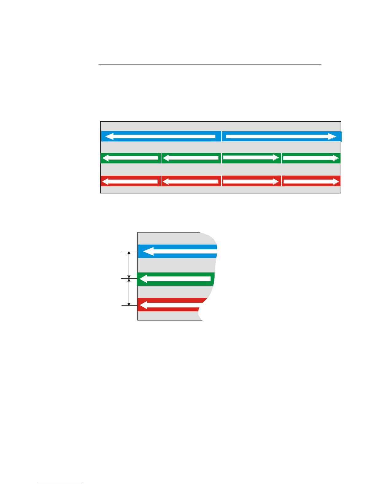
The three color lines are separated
30 µm (4k) or 42 µm (2k) apart
center to center.
1.2 Image Sensor
The Piranha Color camera uses a trilinear CCD sensor with three lines of pixels: one
blue, one red and one green. Depending on your camera model, each line contains
either 2048 or 4096 pixels. As illustrated in the diagram below, the blue line has 2
outputs (taps), and the red and green lines have 4 outputs.
Figure 1: Sensor Block Diagram
Piranha Color Camera 12
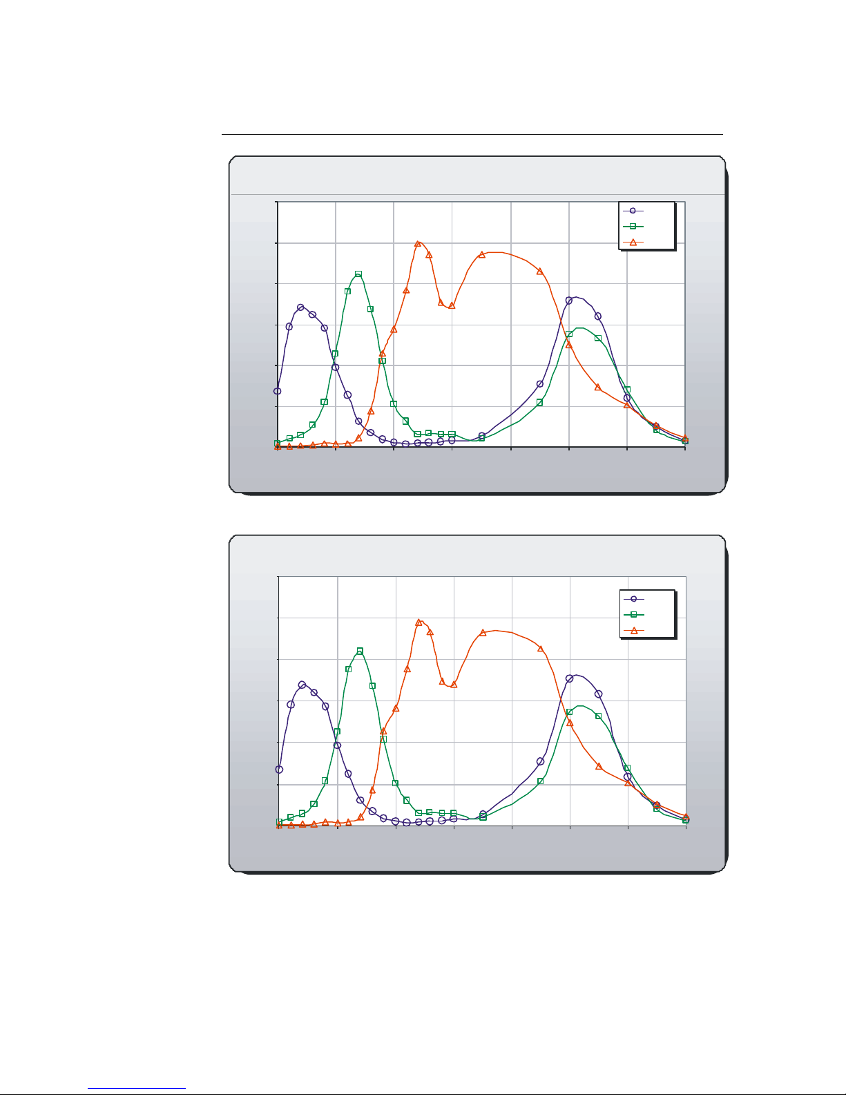
2K Spectral Responsivity, FFC on
0
10
20
30
40
50
60
400 500 600 700 800 900 1000 1100
Wavelength (nm)
Responsivity [DN/(nJ/cm
2
)]
Blue
Green
Red
4K Spectral Responsivity, FFC on
0
5
10
15
20
25
30
400 500 600 700 800 900 1000 1100
Wavelength (nm)
Responsivity[DN/(nJ/cm2)]
Blue
Green
Red
1.3 Responsivity
Piranha Color Camera 13
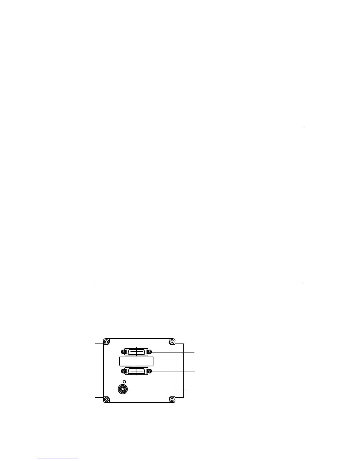
Camera Link Connector
Camera Link Connector
Power Connector
Hardware Interface: Connectors
and Timing
2.1 Installation Overview
When installing your camera, you should take these steps:
1. Power down all equipment.
2. Following the manufacturer’s instructions, install the frame grabber (if applicable).
Be sure to observe all static precautions.
3. Install any necessary imaging software.
4. Before connecting power to the camera, test all power supplies. Ensure that all the
correct voltages are present at the camera end of the power cable. Power supplies
must meet the requirements defined in section 2.2.2 Power Connector.
5. Inspect all cables and connectors prior to installation. Do not use damaged cables
or connectors or the camera may be damaged.
6. Connect Camera Link and power cables.
7. After connecting cables, apply power to the camera.
8. Check the diagnostic LED. See the LED Status Indicator section below for an
LED description.
9. The camera powers on with a baud rate of 9600.
You must also set up the other components of your system, including light sources,
camera mounts, host computers, optics, encoders, and so on.
2.2 Input / Output Connectors and LED
The camera uses:
An LED to display the camera's status.
High-density 26-pin MDR26 connectors for Camera Link control signals, data
signals, and serial communications.
One 6-pin Hirose connector for power.

Piranha Color Camera 14
!
Priority
Color of Status LED
Meaning
1
Flashing Red
Fatal Error. For example, camera temperature is too
high and camera thermal shutdown has occurred.
2
Flashing Green
Camera initialization or executing a long command
(e.g., flat field correction commands ccp or ccf).
During this state, any other sent command is ignored.
3
Solid Green
Camera is operational and functioning correctly and
ready to receive commands.
Hirose 6-pin Circular Male
5
4
6
2
3
1
Mating Part: HIROSE
HR10A-7P-6S
Table 2: Hirose Pin Description
Pin
Description
Pin
Description
1
Min +12 to Max +15V
4
GND
2
Min +12 to Max +15V
5
GND
3
Min +12 to Max +15V
6
GND
Note: Refer to the following sections for details on equipment recommendations and
camera connector information.
2.3 Camera LED
The camera is equipped with a red/green LED used to display the operational status of
the camera. The table below summarizes the operating states of the camera and the
corresponding LED states.
When more than one condition is active, the LED indicates the condition with the
highest priority. The fatal error state is accompanied by corresponding messages further
describing the problem.
Table 1: Diagnostic LED
2.4 Power Connector
Figure 2: Hirose 6-pin Circular Male—Power Connector
The camera requires a single voltage input (+12 V to +15 V). The camera meets all
performance specifications using standard switching power supplies, although wellregulated linear supplies provide optimum performance.
WARNING: When setting up the camera’s power supplies follow these guidelines:
Ensure +12 V to +15 V at the camera power input (after the voltage drop across
the power cable. This may mean that the power supply will have to provide a
voltage greater than the required camera voltage. For example, to achieve +12 V at
the camera, the power supply may need to be +12.5 V or greater.
Protect the camera with a fast-blow fuse between power supply and camera.
Do not use the shield on a multi-conductor cable for ground.
Keep leads as short as possible to reduce voltage drop.
Use high-quality linear supplies to minimize noise.
Use an isolated type power supply to prevent LVDS common mode range
violation.
Note: Camera performance specifications are not guaranteed if your power supply
does not meet these requirements.
Piranha Color Camera 15
Clocking Signal
Indicates
LVAL (high)
Outputting valid line
DVAL (high)
Valid data (unused, tied high)
STROBE (rising edge)
Valid data
FVAL (high)
Outputting valid frame (unused, tied high)
IMPORTANT:
This camera’s
data should be
sampled on the
rising edge of
STROBE.
i
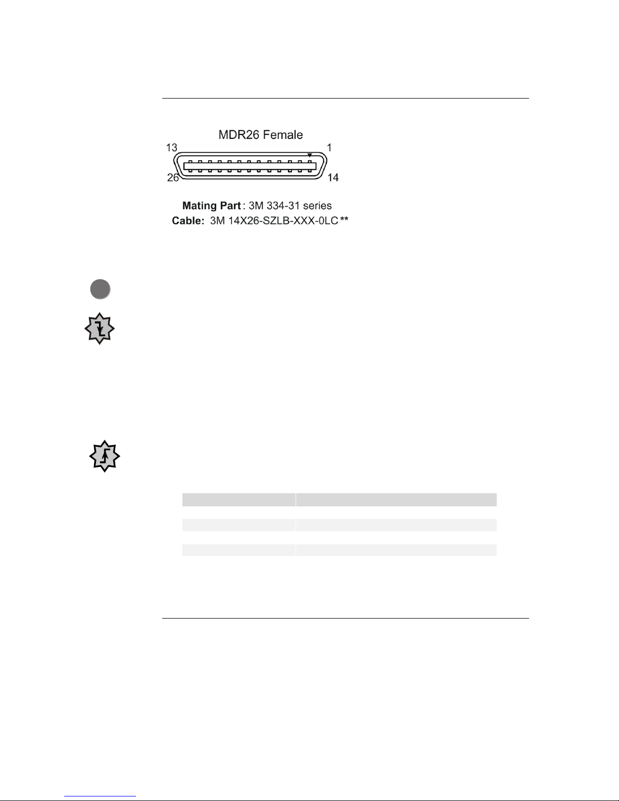
2.5 Camera Link Data Connector
Figure 3: Camera Link MDR26 Connector
Input Signals, Camera Link
The camera accepts control inputs through the Camera Link MDR26F connector.
The camera ships in internal sync, internal programmed integration (exposure mode 2).
EXSYNC (Triggers Line Readout)
Line rate can be set internally using the serial interface. The external control signal
EXSYNC is optional and enabled through the serial interface. This camera uses the
falling edge of EXSYNC to trigger pixel readout.
Direction Control
You control the CCD shift direction through the serial interface. With the software
command, scd, you determine whether the direction control is set via software control
or via the Camera Link control signal on CC3.
Output Signals, Camera Link
These signals indicate when data is valid, allowing you to clock the data from the camera
to your acquisition system. These signals are part of the Camera Link configuration and
you should refer to the Camera Link Roadmap, available from the Knowledge Center
on our website here, for the standard location of these signals.
The camera internally digitizes 12 bits and outputs the 8 MSB or all 12 bits
depending on the camera’s Camera Link operating mode.
2.6 Camera Timing
The Piranha Color camera uses a base or medium Camera Link interface.
Base Configuration
A base configuration uses 1 MDR26 connector and 1 Channel Link chip. The main
characteristics of the base configuration are:
Ports supported: A, B, C.
Piranha Color Camera 16
Base Configuration
One Channel Link Chip + Camera Control + Serial
Communication
Camera
Connector
Right Angle
Frame Grabber
Channel Link
Signal
1 1 inner shield
14
14
inner shield
2
25
X0-
15
12
X0+
3
24
X1-
16
11
X1+
4
23
X2-
17
10
X2+
5
22
Xclk-
18 9 Xclk+
6
21
X3-
19 8 X3+
7
20
SerTC+
20 7 SerTC-
8
19
SerTFG-
21 6 SerTFG+
9
18
CC1-
22 5 CC1+
10
17
CC2+
23 4 CC2-
11
16
CC3-
24 3 CC3+
12
15
CC4+
25 2 CC4-
13
13
inner shield
26
26
inner shield
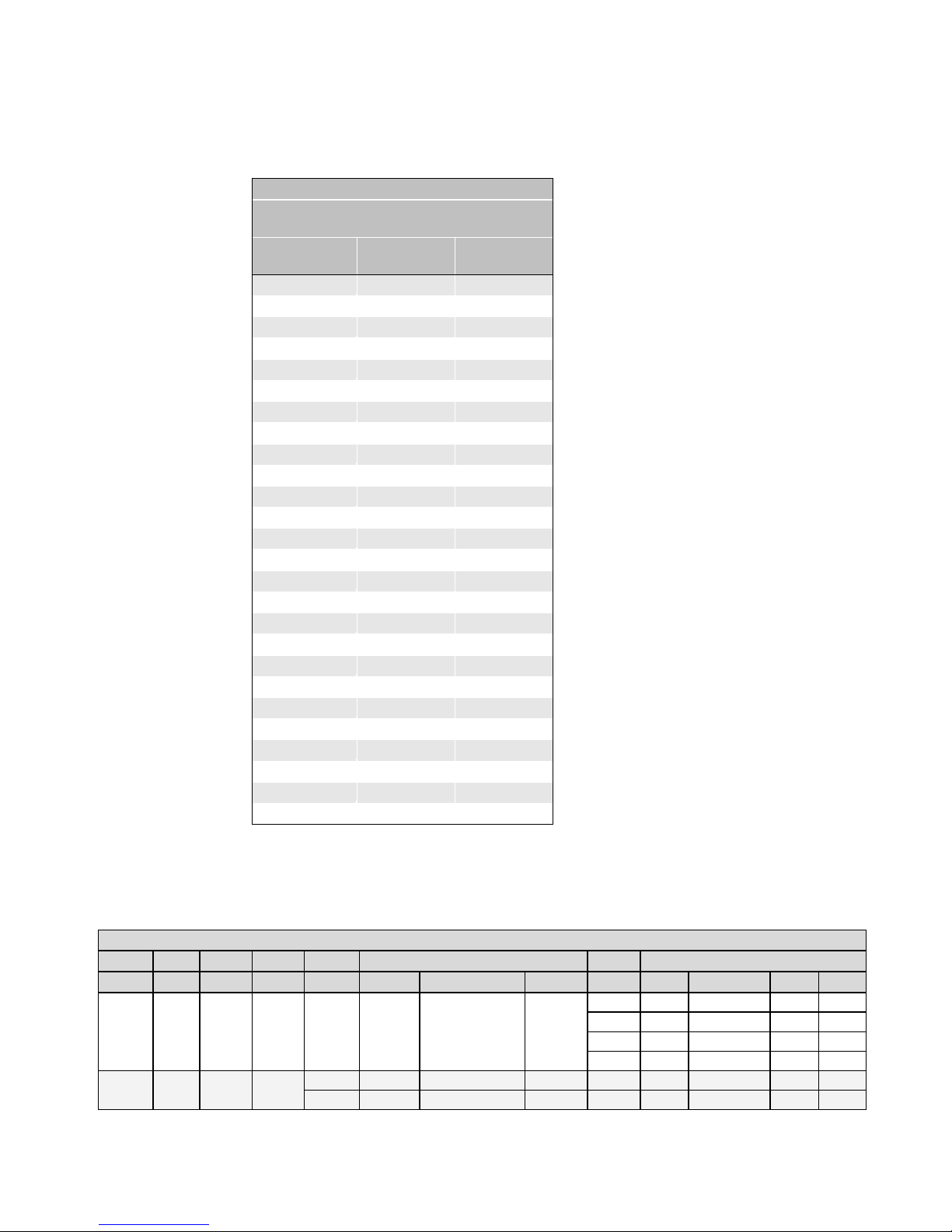
Base Configuration
Connector 1
Maximum SSF8
CLM1
Bits2
Taps3
Lum4
Time5
Port6 A
Port B
Port C
SOT7
2k60
4k60
2k80
4k80
5 8 1
No
NA
R
0-7
G
0-7
B
0-7
30
14.5
7.3
14.5
7.3
40
19.3
9.7
19.3
9.7
60
22.79
12.1
28.99
14.6
80
NA
NA
31.8
17.5
910 8 1
Yes
T0
R
0-7
B
0-7
NA
30
14.5
7.3
14.5
7.3
T1
G
0-7
Y
7-0
NA
40
19.3
9.7
19.3
9.7
Serializer bit width: 28.
Number of chips: 1.
Number of MDR26 connectors: 1.
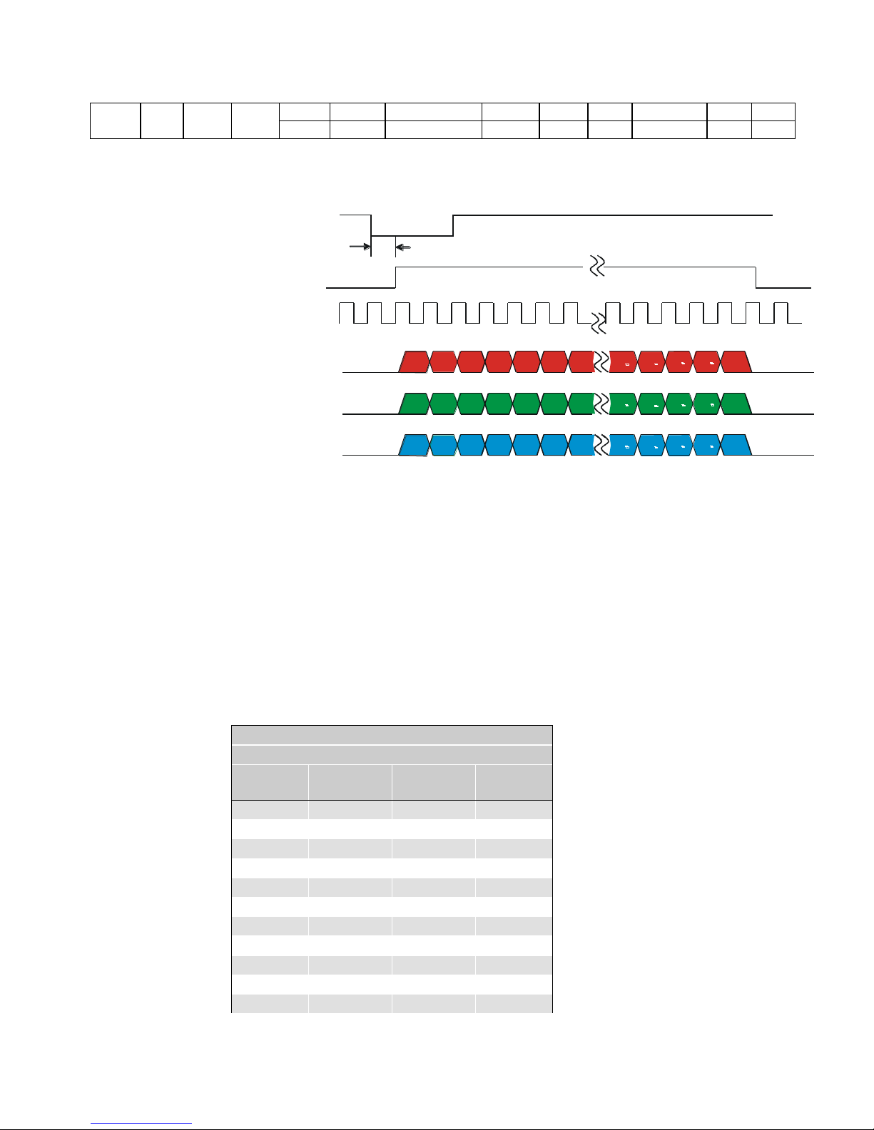
Base Configuration Timing
Each pixel output has 8 bits for each of the three colors (red, green, and blue).
Table 3: Base Configuration Video Data
Piranha Color Camera 17
1010
12 1 Yes
T0
R
0-7
B
8-11R8-11
B
0-7
30
14.5
7.3
14.5
7.3
T1
G
0-7
Y
8-11G8-11
Y
0-7
40
19.3
9.7
19.3
9.7
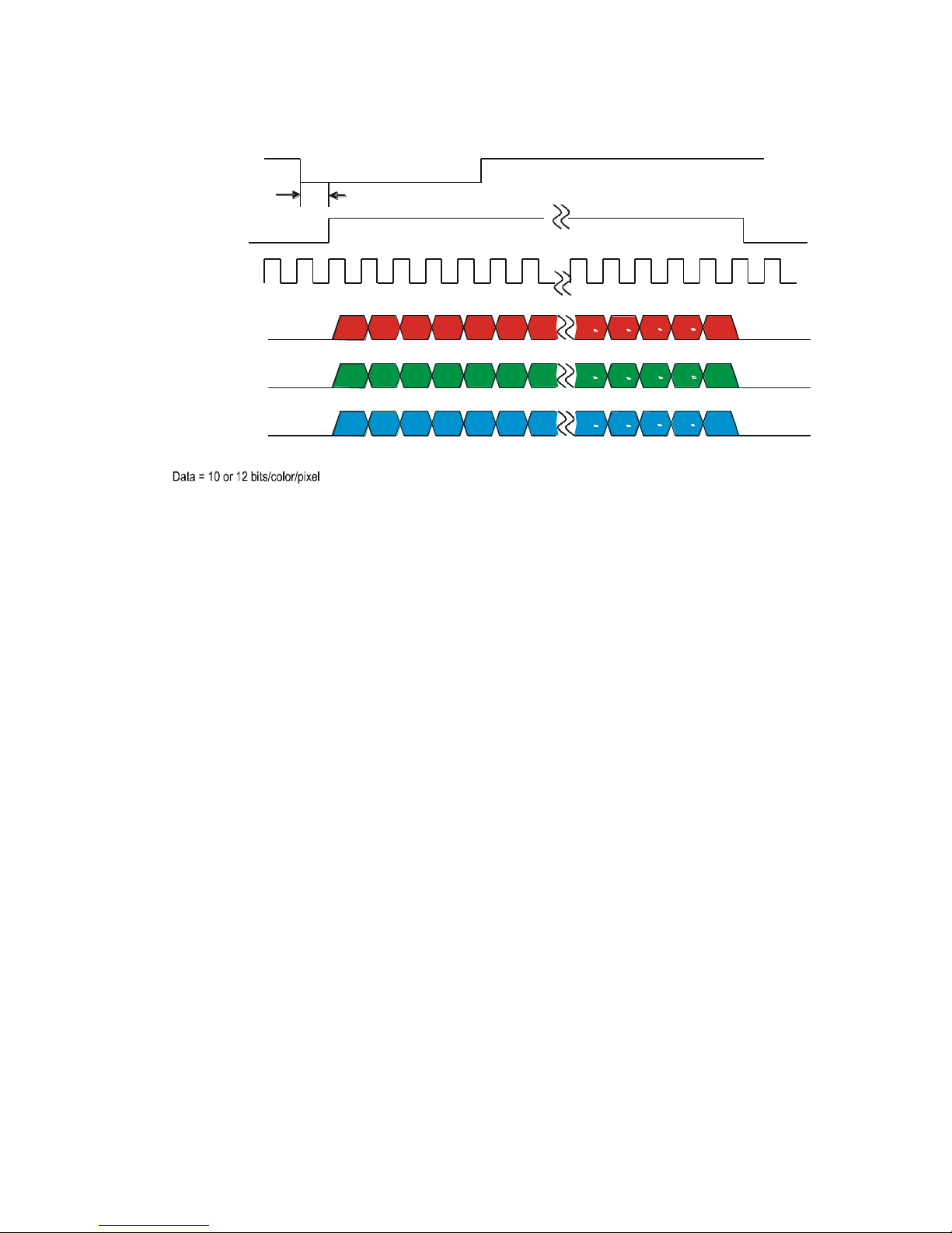
EXSYNC
TBD
R1
R2 R3 R4 R5 R6 R7
Rn 1
Rn
Rn 2
Rn 3
Rn 4
G1
Gn 1
Gn
Gn 2
Gn 3
Gn 4
G2
G3 G4 G5 G6 G7
B1
Bn 1
Bn Bn 2
Bn 3 Bn 4
B2
B3 B4
B5
B6 B7
RED Data
GREEN Data
BLUE Data
n = Number of pixels per line (2048 or 4096)
Data = 8 - bits/color/pixel
Line and Data Valid
Pixel Clock
40 or 80MHz
Medium Configuration (Connector 2)
2 Channel Link Chips
Camera
Connector
Right Angle
Frame Grabber
Channel Link
Signal
Cable Name
1 1 inner shield
Inner Shield
14
14
inner shield
Inner Shield
2
25
Y0-
PAIR1-
15
12
Y0+
PAIR1+
3
24
Y1-
PAIR2-
16
11
Y1+
PAIR2+
4
23
Y2-
PAIR3-
17
10
Y2+
PAIR3+
5
22
Yclk-
PAIR4-
18 9 Yclk+
PAIR4+
6
21
Y3-
PAIR5-
Figure 4: Base Configuration
Medium Configuration
A medium configuration uses 2 MDR26 connectors and 2 Channel Link chips. The
main characteristics of the medium configuration are:
Ports supported: A, B, C, D, E, F.
Serializer bit width: 28.
Number of chips: 2.
Number of MDR26 connectors: 2.

Piranha Color Camera 18
Medium Configuration (Connector 2)
2 Channel Link Chips
Camera
Connector
Right Angle
Frame Grabber
Channel Link
Signal
Cable Name
19 8 Y3+
PAIR5+
7
20
terminated
PAIR6+
20 7 terminated
PAIR6-
8
19
Z0-
PAIR7-
21 6 Z0+
PAIR7+
9
18
Z1-
PAIR8-
22 5 Z1+
PAIR8+
10
17
Z2-
PAIR9+
23 4 Z2+
PAIR9-
11
16
Zclk-
PAIR10-
24 3 Zclk+
PAIR10+
12
15
Z3-
PAIR11+
25 2 Z3+
PAIR11-
13
13
inner shield
Inner Shield
26
26
inner shield
Inner Shield
Notes:
*Exterior Overshield is connected to the shells of the connectors on both ends.
**3M part 14X26-SZLB-XXX-0LC is a complete cable assembly, including connectors.
Unused pairs should be terminated in 100 ohms at both ends of the cable.
Inner shield is connected to signal ground inside camera.
Piranha Color Camera 19
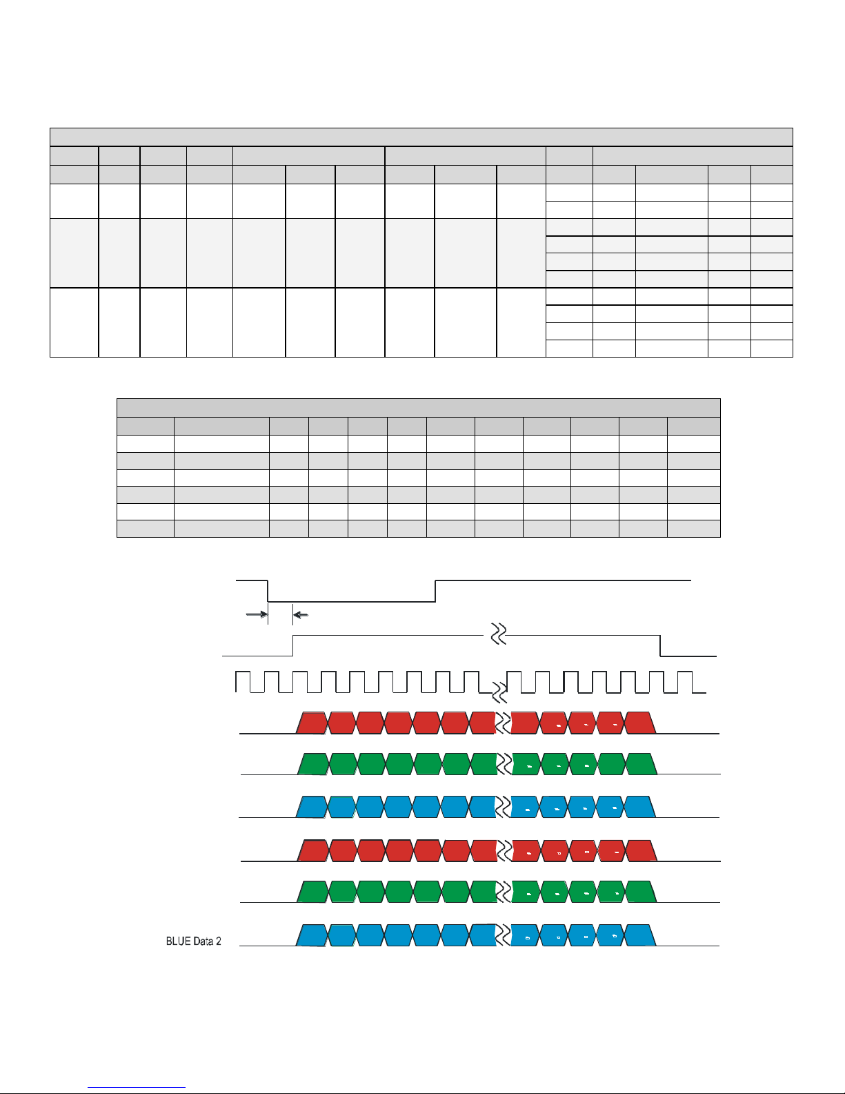
Medium Configuration
Connector 1
Connector 2
Maximum SSF8
CLM1
Bits2
Taps3
Lum4
Port6 A
Port B
Port C
Port D
Port E
Port F
SOT7
2k60
4k60
2k80
4k80
14 8 2
No
R
A
0-7
G
A
0-7
B
A
0-7
R
B
0-7
G
B
0-7
B
B
0-7
60
22.7
12.1
28.6
14.5
80
NA
NA
31.8
17.5
15 8 1
Yes
R
0-7
G
0-7
B
0-7
Y
0-7
NA
NA
30
14.5
7.3
14.5
7.3
40
19.3
9.7
19.3
9.7
60
22.7
12.1
28.9
14.6
80
NA
NA
31.8
17.5
16
12 1 Yes
R
0-7
B
8-11
R
8-11
B
0-7
Y
0-7
G
0-7
Y
8-11
G
8-11
30
14.5
7.2
14.5
7.3
40
19.3
9.7
19.3
9.7
60
22.7
12.1
28.9
14.6
80
NA
NA
31.8
17.5
CLM 14 Pixels are Interleaved
Port
Sequence
1 2 3 4 5 6 7 8 9
10
A
RedA
R1
R3
R5
R7
R9
R11
R13
R15
R17
R19
B
GreenA
G1
G3
G5
G7
G9
G11
G13
G15
G17
G19
C
BlueA
B1
B3
B5
B7
B9
B11
B13
B15
B17
B19 D RedB
R2
R4
R6
R8
R10
R12
R14
R16
R18
R20
E
GreenB
G2
G4
G6
G8
G10
G12
G14
G16
G18
G20
F
BlueB
B2
B4
B6
B8
B10
B12
B14
B16
B18
B20
EXSYNC
TBD
Line and Data Valid
Pixel Clock
40MHz
R1
R3
R5
R7 R9 R11
R13
Rn
1
Rn
Rn
3
Rn 5
Rn
- 7
G1
Gn - 1
Gn
Gn 3
Gn 5
Gn
7
G3
G5 G7
G9 G11
G13
B1
Bn
1
Bn
Bn
3
Bn
5
Bn
7
B3 B5
B7
B11
B13
RED Data 1
BLUE Data 1
GREEN Data 2
GREEN Data 1
G2
Gn
2
Gn Gn
4
Gn
6 Gn
8
G4
G6 G8
G10 G12
G14
RED Data 2
B2
Bn 2
Bn
Bn 4
Bn 6
Bn
8
B4 B6
B8
B10
B12
B14
R2
R4
R6
R8 R10 R12
R14
Rn
2
Rn
Rn
4
Rn
6
Rn
8
B9
Medium Configuration Timing
Figure 5: Medium Configuration (8 Bits/Color/Pixel)
Piranha Color Camera 20
EXSYNC
TBD
R1
R2 R3 R4 R5 R6 R7
Rn 1
Rn
Rn 2
Rn 3
Rn 4
G1
Gn 1
Gn
Gn 2
Gn 3
Gn 4
G2
G3 G4 G5 G6 G7
B1
Bn 1
Bn Bn 2
Bn 3 Bn 4
B2
B3 B4
B5
B6
B7
RED Data
GREEN Data
BLUE Data
n = Number of pixels per line (2048 or 4096)
Line and Data Valid
Pixel Clock
40 or 80MHz
Figure 6: Medium Configuration (12 Bits/Color/Pixel)
Notes for Base and Medium Configuration Timing:
1. CLM: Camera Link Mode.
2. Bits: Number of bits per pixel.
3. Taps: Number of camera link taps per color.
4. Luminance: Indicates if a tap constructed from the RGB using the SCC command
is output.
5. Time: Time multiplex interval.
6. Port : Camera Link port.
7. SOT: Output throughput [mega-pixels / second / color].
8. Maximum SSF: Maximum line rate [kHz] possible in this mode (may be reduced by
SBH, ELS and SRM).
9. The maximum line rate for SOT 60 for the 80 model is greater than the 60 model as
a result of the different readout clocking scheme.
10. Time multiplexing (CLM 9 and 10) is not supported in all frame grabbers.
11. Measurements were made using command settings els 0 and srm 2.

Piranha Color Camera 21
Software Interface: Configuring
the Camera
Using ASCII Commands
All of the camera’s functionality is configurable through its serial interface using the
three-letter commands. You can use any terminal program (e.g. HyperTerminal) to send
serial commands to the camera; however, you must comply with the following serial
protocol:
8 data bits
1 stop bit
No parity
No flow control
9.6 kbps (at power up)
Camera does not echo characters
Command Format
When entering commands please remember the following:
A carriage return <CR> ends each command.
The camera will answer each command with either <CR><LF> OK > or
<CR><LF>Error xx: Error Message > or Warning xx: Warning
Message. The > character is always the last character sent by the camera.
The following parameter conventions are used in the manual:
i = integer value
f = real number
m = member of a set
s = string
t = tap id
x = pixel column number
y = pixel row number
Example: to return the current camera settings:
gcp <CR>
3.1 First Power Up Camera Settings
When the camera is powered up for the first time it operates using the following factory
settings:
Internal forward color scanning direction.
Maximum line rate: 32 kHz (2k) or 17 kHz (4k).
0 dB calibrated analog gain and offset.
Factory calibrated FPN and PRNU coefficients enabled.
8 bit output.

Piranha Color Camera 22
Purpose:
Sets the speed in bps of the serial communication port.
Syntax:
sbr m
Syntax Elements:
m
Baud rate. Available baud rates are: 9600 (Default), 19200,
57600, and 115200.
Notes:
Power-on rate is always 9600 baud.
The rc (reset camera) command will not reset the camera to the
power-on baud rate and will reboot using the last used baud rate.
Example:
sbr 57600
Purpose:
Sets the cable parameters.
Syntax:
scb m
Syntax Elements:
m
Output compare value. Available values are: 0 to 255.
Notes:
In medium configuration, both cables must be the same length.
Only one copy of this setting is saved in the camera (rather than
with each setting).
Using the lfs (load factory settings) command, the cable length
will be set to the factory default of 100.
The cable parameter is a relational value. Increase the value for
longer cables, and decrease it for shorter ones.
Adjust the value until the test pattern (svm 1) is clean.
Example:
scb 75
9600 baud rate.
Exposure mode 2: Internal sync and exposure control.
RGB color selection.
Camera Link mode 5: base configuration, RGB, 8 bit output.
Note: The FPN and PRNU coefficients are factory calibrated at 0 dB gain setting 0. The
FFC calibration line rate is 400 Hz.
3.2 Rebooting the Camera
The reset command (rc) reboots the camera. The camera starts up with the last saved
settings and baud rate used before reboot. Previously saved pixel coefficients are also
restored.
3.3 Baud Rate
3.4 Select Cable
3.5 Help
For quick help the camera can return all available commands and parameters through
the serial interface.

Piranha Color Camera 23
Syntax:
h
Syntax:
gh
Notes:
For more information on the camera’s ―get‖ commands, refer to
section Returning Camera Settings.
There are two different help screens available. One lists all of the available commands to
configure camera operation. The other help screen lists all of the commands available
for retrieving camera parameters (these are called ―get‖ commands).
To view the help screen listing all of the camera configuration commands, use the
command:
To view a help screen listing all of the ―get‖ commands, use the command:
The camera configuration command help screen lists all commands available. Parameter
ranges displayed are the extreme ranges available. Depending on the current camera
operating conditions, you may not be able to obtain these values. If this occurs, values
are clipped and the camera returns a warning message.
Some commands may not be available in your current operating mode. The help screen
displays NA in this case.
The following help screen listing is for a 2k camera:
ccf correction calibrate fpn
ccg calibrate camera gain iti 1-4:0-0:1024-4055
ccp correction calibrate prnu
cil calibrate input lut
clm camera link mode m 5/9/10/14/15/16/
cpa calibrate PRNU algorithm mi 1/2/3/4/:1024 4055
css correction set sample m 1024/2048/4096/
dil display input lut taa 0-0:0-1023:0-1023
dpc display pixel coeffs xx 1-2048:1-2048
ebc enable blue correction i 0-1
eil enable input lut i 0-1
els end of line sequence i 0-2
epc enable pixel coefficients ii 0-1:0-1
gcl get command log
gcm get camera model
gcp get camera parameters
gcs get camera serial
gcv get camera version
get get values s
gfc get fpn coeff x NA
gh get help
gil get input lut ta NA
gl get line xx 1-2048:1-2048
gla get line average xx 1-2048:1-2048
gpc get prnu coeff x NA
gsf get signal frequency i 1-4
h help
lfc load fpn coefficients
lfs load factory settings
lil load input lut
lpc load prnu coefficients
lus load user settings

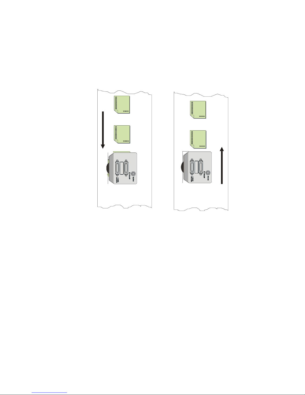
Piranha Color Camera 24
Purpose:
Selects the forward or reverse color scan direction or external
direction control. This accommodates object direction change
on a web and allows you to mount the camera ―upside down.‖
Syntax:
scd i
Syntax Elements:
i
Shift direction. Allowable values are:
0 = Forward CCD shift direction.
rc reset camera
ril reset input lut
roi region of interest xx 1-2048:1-2048
rpc reset pixel coeffs
sab set add background ti 0-0:0-4095
sag set analog gain tf 0-0:-10.0-+10.0
sah set averaging horizontal i 1-2
sao set analog offset ti 0-0:0-255
sbr set baud rate m 9600/19200/57600/
115200/
scb select cable i 0-255
scc set colour correction iiii 0-+4095:-8192 +8191:-8192 +8191:-8192-+8191
scd set ccd direction i 0-2
scl set colour m rgb/r/g/b/
sdo set digital offset ti 0-0:0-4095
sem set exposure mode m 2/3/4/5/6/7/
sfc set fpn coeff xi NA
sfr set fpn range xxi NA
sil set input lut tai NA
slt set lower threshold i 0-4095
smm set mirroring mode i 0-1
sot set output throughput m 30/40/60/80/
spc set prnu coeff xi NA
spr set prnu range xxi NA
srm set readout mode i 0-2
ssa set spatial alignment i 0-6
ssb set subtract background ti 0-0:0-4095
ssf set sync frequency f 1-32362
ssg set system gain ti 0-0:0-65535
ssn set set number i 0-5
sut set upper threshold i 0-4095
svm set video mode i 0-10
ugr update gain reference
vt verify temperature
vv verify voltage
wfc write FPN coefficients
wil write input lut
wpc write PRNU coefficients
wus write user settings
3.6 Sensor Output
Color Scan Direction
Piranha Color Camera 25
1 = Reverse CCD shift direction.
2 = External direction control via Camera Link control:
CC3 (CC3=1 forward, CC3=0 reverse).
Notes:
To obtain the current value of the shift direction, use the
command gcp or get scd.
Related Commands:
smm
Example:
scd 0
Direction of
Object Movement
Camera should operate in
Reverse CCD Shift Direction
scd 1
Direction of
Object Movement
Camera should operate in
Forward CCD Shift Direction
scd 0

Piranha Color Camera 26
Purpose:
Selects the camera’s horizontal readout direction.
Syntax:
smm i
Syntax Elements:
i
Direction of sensor readout
0 = Left to right = 1 to n
1 = Right to left = n to 1
Note:
Pixel readout remains the same after a direction change.
Example:
smm 0
Purpose:
Sets the camera’s Camera Link configuration, number of Camera
Link taps and data bit depth.
Syntax:
clm m
Syntax Elements:
m
5 = Base configuration, RGB, 8 bit output
9 = Base configuration, RGBY, 8 bit output
10 = Base configuration, RGBY, 12 bit output
14 = Medium configuration, 2xRGB, 8 bit output
15 = Medium configuration, RGBY, 8 bit output
16 = Medium configuration, RGBY, 12 bit output
Note:
To obtain the current data mode, use the command
gcp or get clm.
The bit patterns are defined by the Camera Link
Roadmap and the Camera Link Standard. Available
from the Knowledge Center on the Teledyne DALSA
site, here.
Example:
clm 5
Purpose:
The sot command works in conjunction with the clm
command (see previous command) and determines the pixel rate
of the camera.
Syntax:
sot m
Syntax Elements:
m
30 = outputs pixels RGB (triplet) or RGBY (quad) at 30
Mps
40 = outputs pixels RGB (triplet) or RGBY (quad) at 40
Mps
60 = outputs pixels RGB (triplet) or RGBY (quad) at 64
Mps
80 = outputs pixels RGB (triplet) or RGBY (quad) at 80
Mps
Sensor Readout Direction (Mirroring Mode)
3.7 Data Output
Setting the Camera Link Mode
Setting the Camera’s Pixel Rate (Throughput)

Piranha Color Camera 27
Note:
To obtain the current throughput, use the command
gcp or get sot.
The bit patterns are defined by the Camera Link
Roadmap and the Camera Link Standard. Available
from the Knowledge Center on the Teledyne DALSA
site, here.
Changes to the clm may affect this parameter.
Example:
sot 80
Purpose:
Sets the color correction coefficients.
Syntax:
scc Co C1 C2 C3
Syntax Elements:
Co = offset (0 to 4095)
C1 = red multiplier (-8192 to +8191)
C2 = green multiplier (-8192 to +8191)
C3 = blue multiplier (-8192 to +8191)
Note:
Set coefficients used to combine three color streams, e.g.
White = C0 + (C1 x Red) + (C2 x Green) + (C3 x Blue)
C0 is a DN, whereas:
Coefficient = C
1-3
/ 4,096
Modified by set color command (SCL):
RGB: White
R|G|B: Red, Green, or Blue
All colors are not necessary because constructing white is
different
Factory (initial) values combine the three colors equally:
White = 0 + (0.33 x Red) + (0.33 x Green) + (0.33 x Blue)
Cn = 0.33 x 4,096= 1,365
Red = 0 + (1 x Red) + (0 x Green) + (0 x Blue)
C1 = 1 x 4,096= 4,096
Range of {-8,192 to +8,191} is equivalent to floating point
coefficients of {-2.0 to +1.999}
Step size is 0.000244
Values are saved with camera settings
Values may be viewed with GCP or GET SCC
Example:
White = 100 + (0.25 x Red) + (-0.15 x Green) + (0.8 x Blue)
Therefore,
C1 = 0.25 x 4096 = 1024
C2 = (-0.15 x 4096) = -614
C3 = 0.8 x 4096 = 3276
OK>scl RGB
OK>scc 100 1024 -614 3276
3.8 Set Color Correction

Piranha Color Camera 28
Purpose:
Selects the color or colors that you want to adjust with the ccf,
ccg, ccp, cpa, dpc, gfc, gl, gla, gpc, sag, sao, sdo,
set, sfc, spc, ssb, ssg commands.
Syntax:
scl s
Syntax Elements:
s
rgb = adjust all colors (red, green, and blue). Power on
setting.
r = adjust red
g = adjust green
b = adjust blue
Note:
The camera always powers up using scl rgb.
Example:
scl b
Color selection limits the taps that can be selected in these commands as follows:
scl
Tap
Notes
rgb
0
All 10 camera taps
r
0
1 to 4
All 4 red taps
Single red tap
g
0
1 to 4
All green taps
Single green tap
b
0
1 to 2
All blue taps (2)
Single blue tap
Purpose:
When saving and loading camera settings, you have a choice of
saving up to four different sets and loading from five different
sets (four user and one factory). This command determines the
set number from where these values are loaded and saved. The
set number is saved along with the camera settings when the
wus command is issued.
Syntax:
ssn i
Syntax Elements:
i
0 = Factory set. Settings can only be loaded from this set.
1 - 4 = User sets. You can save, or load settings with these
sets.
Note:
The camera powers up with the last set saved using this
command.
Related Commands
wus, lus, wil, lil, wfc, lfc
3.9 Camera Selection Variables
There are some camera condition variables that you should determine before adjusting
any digital or analog settings like gain or offset, or before changing the camera’s
exposure time. These variables are:
The color (or colors) that you want to adjust.
The set number where you want to save any of these adjustments.
The region of interest for performing these adjustments.
Setting the Color Variable
Selecting the Set Number

Piranha Color Camera 29
Example:
ssn 3
Purpose:
Sets the pixel range used to collect the end-of-line statistics and
sets the region of pixels used in the ccg, gl, gla, ccf, and
ccp commands.
In most applications, the field of view exceeds the required object
size and these extraneous areas should be ignored. It is
recommended that you set the region of interest a few pixels
inside the actual useable image.
Syntax:
roi x1 x2
Syntax Elements:
x1
Column start number. Must be less than the pixel end number
in a range from 1 to sensor resolution.
x2
Column end. Must be greater than the pixel start number in a
range from 1 to sensor resolution.
Notes:
To return the current region of interest, use the commands gcp
or get roi.
Related Commands
ccg, gl, gla, ccf, ccp, cpa, els
Example:
roi 10 50
You must first set the camera exposure mode using the sem command.
Next, if using mode 2 or 7 use the commands ssf and set to set the line rate and exposure
time.
Purpose:
Sets the camera’s exposure mode allowing you to control your sync,
exposure time, and line rate generation.
Syntax:
sem i
Syntax Elements:
i
Exposure mode to use. Factory setting is 2.
Notes:
Refer to Table 4: Color Exposure Modes for a quick list of available
modes or to the following sections for a more detailed explanation.
To obtain the current value of the exposure mode, use the command
gcp or get sem.
Related Commands:
ssf, set
Example:
sem 3
Setting a Region of Interest (ROI)
3.10 Exposure Control
Overview
You have a choice of operating in one of six exposure modes. The camera’s line rate
(synchronization) can be generated internally through the software command ssf or set
externally with an EXSYNC signal, depending on your mode of operation. To select
how you want the camera’s line rate to be generated:
Setting the Exposure Mode

Piranha Color Camera 30
Mode
SYNC
Exposure
Control
Description
2
Internal
Internal
Each color may have a different exposure time.
3
External
None
All colors share the same exposure time.
4
External
External
Smart EXSYNC. All colors share same exposure time.
5
External
External
Each color may have a different exposure time.
6
External
Internal
Each color may have a different exposure time.
7
Internal
None
All colors share the same exposure time.
Table 4: Color Exposure Modes
Note: When setting the camera to external signal modes, EXSYNC and/or PRIN must
be supplied.

Piranha Color Camera 31
Exposure Modes in Detail

Piranha Color Camera 32
Purpose:
Sets the camera’s line rate in Hz. Camera must be operating in
exposure mode 2 or 7.
Syntax:
ssf f
Syntax Elements:
f
Desired line rate in Hz. Allowable values are:
2k80: 1 to 32362 Hz
2k60: 1 to 22714 Hz
4k80: 1 to 17699 Hz
4k60: 1 to 12132 Hz
Notes:
To read the current line frequency, use the command gcp or get
ssf.
If you enter an invalid line rate frequency, an error message is
returned.
Line rate reduces depending on clm, sut, els, and sah
settings.
Values less than 5000 Hz will return the warning: "Warning 01:
Outside of specification>".
Related Commands:
sem, set
Example:
ssf 10000
Purpose:
Sets the camera’s exposure time in micro seconds. Camera must be
operating in mode 2 or 6.
Syntax:
set f
Syntax Elements:
f
Desired exposure time in µs. Allowable range is 5.0 to
9997.000.0 µs.
Notes:
To read the current exposure time, use the command gcp or get
set.
The ssf and set commands will "push" each other when set.
i
Applies to
Modes 2 and 7
i
Applies to
Modes 2 and 8
Setting the Line Rate
Setting the Exposure Time

Piranha Color Camera 33
Related Commands:
sem, ssf
Example:
set 400.5
Blue
Green
Red
Sensor
Object
As the object travels along the web, the object passes the three color lines at different points in time.
As a result, the camera uses spatial correction to reconstruct the image.
Direction of object movement.
3.11 Spatial Correction
Spatial Correction and Trilinear Sensor Design
The trilinear sensors three color lines do not share a common optical axis. This results
in the three color lines imaging three separate object points.
As a result, the color images need to be stored, delayed and recombined to properly
reconstruct the color image. This characteristic is referred to as spatial correction.
The Piranha Color sensor uses proprietary design to minimize the center to center
spacing to 30 µm (4k) or 42 µm (2k).

Piranha Color Camera 34
Red Tap 2
Red Tap
1
Blue Tap
1
Green Tap 2
Green Tap
1
30 µm (4k)
42 µm (2k)
30 µm (4k)
42 µm (2k)
The three color lines are separated
30 µm (4k) or 42 µm (2k) apart
center-to-center.
The trilinear CCD sensor used in the Piranha Color camera has three linear arrays for
Red (R), Green (G) and Blue (B) color channel, respectively. The inter-array spacing
between color channels is 3 lines apart centre-to-centre. Because of the spacing between
the linear arrays, each array will have a slightly different view of an object that is passing
before the camera. Therefore, for each exposure, each color array in the sensor captures
an image of a slightly different area on the object.
The spatial correction process is used to properly reconstruct the full color (RGB) image
of the object. For example, assuming that the following parameters are used:
The system uses a magnification of 1/10, i.e., an area of 0.1 mm x 0.1 mm on the object
will have an image of 10 µm x 10 µm on the sensor;
The encoder is set to have a step of 0.1 mm in the movement of the web; i.e., the image
on the sensor will move 10 µm for each step of the encoder;
The image is line captured at each step of the encoder;
The moving object A from the view of line of Red channel to that of Green channel is 3
steps, i.e.:
3 steps x 0.1 mm/step x 1/10 magnification = 30 µm movement of the image on the
sensor.
There are 3 more steps to move the image of object A further from the Green channel
to the Blue channel.
To properly reconstruct the full RGB image of the object A, the user needs to combine
the Red channel data captured at line capture #0 with Green data captured at capture
#3 and Blue data captured at capture #6. A parameter Line Delay is used to specify
which line captures should be combined to properly reconstruct the image. In the
above case, the Line Delay is 3. In general,
Inter-array spacing (30 µm or 42 µm)
Line Delay = -----------------------------------------------------
Step of encoder (µm) x magnification

Piranha Color Camera 35
Purpose:
Sets the number of lines of delay between colors that are read out
from the sensor.
Syntax:
ssa i
Syntax Elements:
i
Line delay between colors in a range from 0-6.
Notes:
To read the current line delay, use the command gcp or get ssa.
If your line rate matches the speed of the object, then the value of
the line delay will be 3.
Adjust the ssa value until you remove the red and blue halos
above and below a black on white horizontal line in order to set
the line delay.
Example:
ssa 3
Purpose:
Averaging reduces the pixel noise and decreases the horizontal
resolution. The charge collected in adjacent pixels is averaged
together.
Syntax:
sah i
Syntax Elements:
i
The number of horizontal pixels to average. Available values
are 1 (factory setting) and 2.
The Piranha Color is a bi-directional camera and the direction of the web movement
can be arranged in either way. If the object is passing the camera in the other direction,
its image will pass over the Blue channel first, then the Green channel, and finally the
Red channel. In order to properly construct a full color (RGB) image, the system needs
to know the direction of the movement. Another parameter, color scan direction (scd),
is used to specify the direction of web movement.
Setting the Line Delay between Colors
3.12 Averaging Horizontal Pixels
Setting the Averaging Horizontal

Piranha Color Camera 36
Notes:
Selecting sah 1 results in no averaging.
Selecting sah 2 averages pairs of pixels: (P1+P2)/2,
(P3+P4)/2, (P5+P6)/2…
If you are using averaging, the minimum, maximum, and
mean statistics generated by the gl or gla commands
and used by the ccg, cao, ccf, and ccp commands are
for the un-averaged pixels.
Changing the averaging does not require the recalibration
(analog gain, FPN or PRNU) of the camera.
The current value of horizontal averaging factor can be
obtained using the gcp or get sah commands.
Horizontal averaging does not affect the CCD readout
time, but it does affect FIFO readout as all the pixels still
need to be read out of the CCD, but only the averaged
pixels stored in the FIFO (line store).
ROI will be pushed out to include both averaged pixels at
each end (e.g. if the ROI was 4-2048, the start value
would be changed to 3, since the first averaged pixel
consists of sensor pixels 3 and 4).
Example:
sah 2
Analog Processing
Digital Processing
analog video
analog
gain
analog
offset
FPN
coefficients
digital
offset
PRNU
coefficients
background
subtract
digital system
gain
sag,ccg
sao
ccf
sdo
ccp,cpa ssb
ssg
background
addition
digital video
sab
background
addition
digital video
eil
LUT
addition
3.13 Processing Chain Overview and
Description
The following diagram shows a simplified block diagram of the camera’s analog and
digital processing chain. The analog processing chain begins with an analog gain
adjustment, followed by an analog offset adjustment. These adjustments are applied to
the video analog signal prior to its digitization by an A/D converter.
The digital processing chain contains the spatial correction, non-linearity look-up table
(LUT) correction, FPN correction, the PRNU correction, the background subtract, the
digital gain, and the background add. All of these elements are user programmable.
Figure 7: Signal Processing Chain

Piranha Color Camera 37
Analog Processing
Optimizing offset performance and gain in the analog domain allows you to achieve
a better signal-to-noise ratio and dynamic range use. Perform all analog adjustments
prior to any digital adjustments.
Analog gain (sag or ccg command) is multiplied by the analog signal to increase
the signal strength before the A/D conversion (and before noise is added to the
signal).
The analog offset (sao command) or black level is an ―artificial‖ offset introduced
into the video path to ensure that the A/D is functioning properly. The analog
offset should be set so that it is at least 3 times the RMS noise value at the current
gain.
Digital Processing
To optimize camera performance, complete all analog adjustments before digital
signal adjustments.
Fixed pattern noise (FPN) calibration (calculated using the ccf command) is used
to subtract away individual pixel dark current.
The digital offset (sdo command) enables the subtraction of the ―artificial‖ A/D
offset (the analog offset) so that application of the PRNU coefficient doesn’t result
in artifacts at low light levels due to the offset value. You may want to set the sdo
value if you are not using FPN correction but want to perform PRNU correction.
Photo-Response Non-Uniformity (PRNU) coefficients (calculated using the ccp or
cpa commands) are used to correct the difference in responsivity of individual
pixels (i.e. given the same amount of light different pixels will charge up at different
rates) and the difference in light intensity across the image either because of the
light source or due to optical aberrations (e.g. there may be more light in the center
of the image). PRNU coefficients are multipliers and are defined to be of a value
greater than or equal to 1. This ensures that all pixels will saturate together.
Background subtract (ssb command) and system (digital) gain (ssg command) are
used to increase image contrast after FPN and PRNU calibration. It is useful for
systems that process 8-bit data but want to take advantage of the camera’s 12 bit
digital processing chain. For example, if you find that your image is consistently
between 128 and 255DN(8 bit), you can subtract off 128 (ssb 2048) and then
multiply by 2 (ssg 0 8192) to get an output range from 0 to 255.
Background addition (sab command) is used to ensure a minimum output value,
and is added to the digital video after the system gain is applied.
The Effects of the Processing Chain on Calibration
The Processing Chain (as shown in Figure 7):
Video out = (([video in] x SAG + SAO - SDO - FPN) x PRNU – SSB) x SSG +
SSB
Calibration takes place at the output of the parameter being calibrated. If the parameters
further down the chain are not zero or unity, then the video out may not be as expected.
For example, if the analog gain is calibrated to an average of 3,000 DN using ―CCG 2 0
3000‖ while SSB is 100, the average video output will be 2,900 DN not 3,000 DN.
This applies to:
CCG: calibrate analog gain (SAG) or system gain (SSG)

Piranha Color Camera 38
Purpose:
Sets the camera’s analog gain value. Analog gain is multiplied by
the analog signal to increase the signal strength before the A/D
conversion. It is used to take advantage of the full dynamic
range of the A/D converter.
Syntax:
sag t f
Syntax Elements:
t
Tap selection. Use 0 for all taps. Color selection limits the
taps that may be selected by this command. See scl for
further information.
f
Gain value in a range from –10 to +10dB.
Notes:
To return the current analog gain setting, use the command gcp
or get sag.
Example:
sag 0 5.2
Related Commands:
ccg
Purpose:
Instead of manually setting the analog gain to a specific value, the camera can
determine appropriate gain values. This command calculates and sets the analog
gain according to the algorithm determined by the first parameter.
Syntax:
ccg i t i
Syntax
Elements:
i
Calibration algorithm to use.
1 = This algorithm adjusts analog gain so that 8% to 13% of tap region of
interest (ROI) pixels are above the specified target value.
CCF: calibrate FPN
CCP: calibrate PRNU
CPA: calibrate analog gain (SAG) and PRNU
PRNU calibration includes the FPN whether it is enabled or not (as they are linked). If
you do not want the PRNU calibration to include the effect of FPN then it should be
zeroed first using the RPC command.
CCG 3 (system gain) only includes FPN and PRNU if they are enabled with EPC.
Note: Refer to section 3.9 Camera Selection Variables for details on commands that
should be set before performing any analog or digital adjustments.
3.14 Analog Gain and Analog Offset
All analog signal processing chain commands should be performed prior to FPN and
PRNU calibration and prior to digital signal processing commands.
Setting Analog Gain
Calibrating Camera Gain

Piranha Color Camera 39
10% Above
Target
Before
Calibration
Algorithm One
2 = This algorithm adjusts analog gain so that the average pixel value in tap’s
ROI is equal to the specified target value.
Algorithm Two
Mean
Target
Before
Calibration
3 = This algorithm adjusts digital gain so that the average pixel value in tap’s
ROI is equal to the specified target.
Note: See Alogrithm Two above for an illustration.
4 = This algorithm adjusts the analog gain so that the peak tap ROI pixels are
adjusted to the specified target.

Piranha Color Camera 40
Peak
Target
Before
Calibration
Algorithm Four
t Tap value. Use 0 for all taps. Color selection limits the taps that may be
selected by this command. See scl for further information.
i
Calculation target value in a range from 1024 to 4055DN (12 bit LSB).
Notes:
Analog gain calibration requires constant light on a clean, white reference. White
plastic or white ceramic is ideal.
If very few tap pixels are within the ROI, gain calculation may not be optimal.
When all taps are selected, taps outside of the ROI are set to the average gain of the
taps that are within the ROI.
Perform analog gain algorithms before performing FPN and PRNU calibration.
All digital settings affect the analog gain calibration. If you do not want the digital
processing to have any effect on the camera gain calibration, then turn off all digital
settings by sending the commands: sdo 0 0, epc 0 0, ssb 0 0, ssg 0
4096, and sab 0 0.
Example:
ccg 2 0 3040
Related
Commands:
sag, ssg
Purpose:
Sets the analog offset. The analog offset should be set so that it
is at least 3 times the RMS noise value at the current gain. The
analog offset for noise is configured at the maximum specified
gain and as a result you should not need to adjust the analog
offset.
Syntax:
sao t i
Syntax Elements:
t
Tap selection. Use 0 for all taps. Color selection limits the
taps that may be selected by this command. See scl for
further information.
i
Offset value in a range from 0 to 255DN (12 bit LSB).
Notes:
To return the current analog offset value, use the command
gcp or get sao.
Setting Analog Offset

Piranha Color Camera 41
Example:
sao 2 35
Related Commands:
cao
Analog Processing
Digital Processing
analog video
analog
gain
analog
offset
FPN
coefficients
digital
offset
PRNU
coefficients
background
subtract
digital system
gain
sag,ccg
sao
ccf
sdo
ccp,cpa ssb
ssg
background
addition
digital video
sab
background
addition
digital video
eil
LUT
addition
where
V
output
=
digital output pixel value
V
input
=
digital input pixel value from the CCD
PRNU( pixel)
=
PRNU correction coefficient for this pixel
FPN( pixel )
=
FPN correction coefficient for this pixel
Background Subtract
=
background subtract value
System Gain
=
digital gain value
Background Addition
=
background addition value
Note: If your
illumination
or white
reference
does not
extend the
full field of
view of the
camera, the
camera will
send a
warning.
3.15 Flat Field Correction
Flat Field Correction Overview
This camera has the ability to calculate correction coefficients in order to remove nonuniformity in the image. This video correction operates on a pixel-by-pixel basis and
implements a two point correction for each pixel. This correction can reduce or
eliminate image distortion caused by the following factors:
Fixed Pattern Noise (FPN)
Photo Response Non Uniformity (PRNU)
Lens and light source non-uniformity Correction is implemented such that for each
pixel:
V
=[(V
output
System Gain + Background Addition
The algorithm is performed in two steps. The fixed offset (FPN) is determined first by
performing a calibration without any light. This calibration determines exactly how
much offset to subtract per pixel in order to obtain flat (zero) output when the CCD is
not exposed.
The white light calibration is performed next to determine the multiplication factors
required to bring each pixel to the required value (target) for flat, white output. Video
output is set slightly above the brightest pixel (depending on offset subtracted).
- FPN( pixel ) - digital offset) * PRNU(pixel) – Background Subtract] x
input

Piranha Color Camera 42
Brightest Pixel (per tap)
Darkest Pixel (per tap)
3>
Flat Field Correction Restrictions
It is important to do the FPN correction first. Results of the FPN correction are used in
the PRNU procedure. We recommend that you repeat the correction when a
temperature change greater than 10°C occurs or if you change the analog gain,
integration time, line rate, or SRM.
PRNU correction requires a clean, white reference. The quality of this reference is
important for proper calibration. White paper is often not sufficient because the grain in
the white paper will distort the correction. White plastic or white ceramic will lead to
better balancing.
For best results, ensure that:
50 or 60 Hz ambient light flicker is sufficiently low so as not to affect camera
performance and calibration results.
The analog gain should be adjusted for the expected operating conditions.
The ratio of the brightest to darkest pixel in a tap should be less than 3 to 1, where:
The brightest pixel should be slightly below the target output.
When greater than 6.25% of the pixels from a single row within the region of interest
are clipped, then flat field correction results may be inaccurate.
Correction results are valid only for the current analog gain and offset values. If you
change these values, it is recommended that you recalculate your coefficients.

Piranha Color Camera 43
Set up the camera operating environment
(i.e. line rate, exposure, offset, gain, etc.)
Set the calibration sample size using
the command css. It is recommended that
you use the default setting.
Perform FPN calculation
Perform PRNU calculation
1. Stop all light from entering the camera. (Tip: Cover lens with a lens cap.)
2. Verify that the output signal level is within range by issuing the command
or . If there are too many zeros in the output data (more than 6.25%
of output data within the roi) , increase the analog offset ( ) or use the
automated algorithm . If the average of the pixels is too high for your
application, reduce the analog offset or gain level ( ).
3. Issue the command . The camera will respond withOK> (if no error occurs).
FPN calculation automatically calibrates FPN coefficients and digital offset.
4. After the calibration is complete, you should save these settings to non-volatile
memory so they be reusable on reboot. To do so, issue the commands and
.
5. To verify output, enable the FPN coefficients using the command .
You should see close to zero output.
gl gla
sao
cao 0
sag
wfc
wus
epc 1 0
i
1. Place a white reference in front of the camera.
2. Verify that the output signal level is within range by issuing the command
or . If the signal level is too low, increase your light level, adjust the analog
gain ( ) or use the automated algorithm .
DALSA recommends a target value of about 80% of saturation. If you change
the gain, FPN coefficients should be recalculated.
3. Issue the command . The camera will respond with OK>( if no error occurs).
4. After the calculation is complete, you can save these settings to non-volatile
memory so they will be remembered after power-down and direction change.
To do so, issue the commands and
5
gl
gla
sag ccg i 0 i
ccp
wpc wus.
. Enable the coefficients using the command, .epc 1 1
Perform PRNU calculation next to determine the multiplication
factors required to bring each pixel to the required value (balance target) for
flat, white output.
Set the region of interest to include all
of the image’s pixels of importance using
the command roi x1 y1 x2 y2. You can use
the default if you want to calibrate all pixels.
Digital offset and digital system gain, and background subtract and
add values should be set to zero ( , , , )ssb 0 0sdo 0 0ssg 0 0sab 0 0
Purpose:
Measures fixed pattern noise (FPN).
Syntax:
ccf
Notes:
Before sending this command, use the scl command to
select the color or colors you want to adjust. This allows
you to limit the calibration to a single color.
Perform all analog and digital adjustments before
performing FPN correction.
Perform FPN correction before PRNU correction.
To save FPN coefficients after calibration, use the wfc command.
FPN Measurement
Performing FPN Measurement

Piranha Color Camera 44
Related Commands:
ccp, wfc
Example:
ccf
Purpose:
Sets an individual pixel’s FPN coefficient.
Syntax
sfc x i
Syntax Elements:
x The pixel number from 1 to sensor pixel count.
i
Coefficient value in a range from 0 to 4095 (12 bit LSB).
Notes:
Before sending this command, use the scl command to select the
color you want to adjust.
Example:
sfc 10 50
Purpose:
Sets a range of pixel FPN coefficients.
Syntax
sfr x x i
Syntax Elements:
x
The first pixel number of the range.
x
The last pixel number of the range.
i
Coefficient value in a range from 0-2048.
Notes:
Before sending this command, use the scl command to
select the color you want to adjust.
The first pixel of the range must be less than the last.
Example:
sfr 1 100 80
Purpose:
Calculate the PRNU coefficients to eliminate the difference in
responsivity between the pixels, thereby creating a uniform response to
light. Using this command, you must provide a calibration target.
Syntax:
cpa i1 i2
Syntax Elements:
i1
PRNU calibration algorithm to use:
1 = This algorithm first adjusts each tap’s analog gain so that
8-13% of pixels within a tap are above the value specified in
the target value parameter. PRNU calibration then occurs using
the peak pixel in the region of interest.
This algorithm is recommended for use only when FPN is
negligible and FPN coefficients are set to zero. Since this
algorithm adjusts the analog gain, it also affects FPN. If FPN is
calibrated prior to running this algorithm, FPN will be
observable in dark conditions and an incorrect FPN value will
be used during PRNU calibration resulting in incorrect PRNU
coefficients.
2 = Calculates the PRNU coefficients using the entered target
Setting a Pixel’s FPN Coefficient
Setting a Range of FPN Coefficients
PRNU Calculation
Performing PRNU to a user entered value

Piranha Color Camera 45
value as shown below:
PRNU Coefficient =
Target
(AVG Pixel Value ) - (FPN + value)sdo
i
i
i
The calculation is performed for all sensor pixels but warnings
are only applied to pixels in the region of interest. This
algorithm is useful for achieving uniform output across
multiple cameras. It is important that the target value (set with
the next parameter) is set to be at least equal to the highest
pixel across all cameras so that all pixels can reach the highest
pixel value during calibration. Confirm this using the gla
statistics.
3 = This algorithm includes an analog gain adjustment prior to
PRNU calibration. Analog gain is first adjusted so that the peak
pixel value in tap’s ROI is within 97 to 99% of the specified
target value. It then calculates the PRNU coefficients using the
target value as shown below:
PRNU Coefficient =
Target
(AVG Pixel Value ) - (FPN + value)sdo
i
i
i
The calculation is performed for all sensor pixels but warnings
are only applied to pixels in the region of interest. This
algorithm is useful for achieving uniform output across
multiple cameras.
This algorithm is should be used only when FPN is negligible
and FPN coefficients are set to zero. Since this algorithm
adjusts the analog gain, it also affects FPN. If FPN is calibrated
prior to running this algorithm, FPN will be observable in dark
conditions and an incorrect FPN value will be used during
PRNU calibration resulting in incorrect PRNU coefficients.
This algorithm is more robust and repeatable than algorithm 1
because it uses an average pixel value rather than a number
above target. However, this algorithm is slower.
4 = Calculates the PRNU coefficient in the same way as cpa 2
with the exception that this command only calculates PRNU
for pixels within the current Region of Interest (ROI).
i2
Peak target value in a range from 1024 to 4055DN. The target
value must be greater than the current peak output value.
Notes:
Perform all analog adjustments before calibrating PRNU.
This command performs the same function as the cpp
command with the exception that you enter a target value.
Calibrate FPN before calibrating PRNU. If you are not
performing FPN calibration then issue the rpc (reset pixel
coefficients) command and set the sdo (set digital offset)
value so that the output is near zero under dark.
Example:
cpa 1 600
Purpose:
Performs PRNU correction and eliminates the difference in
responsivity between the most and least sensitive pixel creating a
uniform response to light.
Syntax
ccp
Performing PRNU Calculation to a Camera Calculated Value

Piranha Color Camera 46
Notes:
Before sending this command, use the scl command to
select the color or colors you want to adjust. This
allows you to limit the calibration to a single color.
Perform all analog adjustments before calculating
PRNU.
Perform FPN correction before PRNU correction.
If FPN cannot be calibrated, use the rpc command to
reset all coefficients to zero, and save them to memory
with the wfc command. You can then adjust the digital
offset (sdo command) to remove some of the FPN.
Ensure camera is operating at its expected analog gain,
integration time, and temperature.
To save PRNU coefficients after calibration, use the
wpc command.
Related Commands:
ccf, cpa
Purpose:
Sets an individual pixel’s PRNU coefficient.
Syntax:
spc i1 i2
Syntax Elements:
i1
The pixel number from 1 to n, where n = 2048 or 4096
depending on the resolution.
i2
Coefficient value in a range from 0 to 61438 where:
Notes:
Before sending this command, use the scl command to select the
color you want to adjust.
Example:
spc 1024 10000
Purpose:
Sets a range of pixel PRNU coefficients.
Syntax:
spr i1 i2 i3
Syntax Elements:
i1
The first pixel number of the range.
i2
The last pixel number of the range.
i3
Coefficient value in a range from 0 to 61438 where:
Notes:
Before sending this command, use the scl command to select the
color or colors you want to adjust. This allows you to limit the
calibration to a single color.
i2
4096
1 +
prnu coefficient =
i3
4096
1 +
prnu coefficient =
Setting a Pixel’s PRNU Coefficient
Setting a range of Pixel PRNU Coefficients

Piranha Color Camera 47
The first pixel of the range must be less than the last.
Example:
spr 4001 4096 0
Purpose:
Returns all the current pixel coefficients in the order FPN, PRNU,
FPN, PRNU… for the range specified by x1 and x2.
Syntax:
dpc x1 x2
Syntax Elements:
x1
Start pixel to display in a range from 1 to n, where n = 2048 or
4096 depending on the resolution.
x2
End pixel to display in a range from x1 to n, where n = 2048 or
4096 depending on the resolution.
Notes:
This function returns all the current pixel coefficients in the order
FPN, PRNU, FPN, PRNU…
Limited by the scl color selection.
Example:
dpc 10 20
Purpose:
Returns a pixel’s FPN coefficient value in DN (12 bit LSB)
Syntax:
gfc i
Syntax Elements:
i
The pixel number to read in a range from 1 to sensor
pixel count.
Notes:
Before sending this command, use the scl command to select the
color you want to adjust.
Example:
gfc 10
Purpose:
Returns a pixel’s PRNU coefficient value in DN (12 bit LSB)
Syntax:
gpc i
Syntax Elements:
i
The pixel number to read in a range from 1 to sensor
pixel count.
Notes:
Before sending this command, use the scl command to select the
color you want to adjust.
Example:
gpc 10
Purpose:
Enables and disables FPN and PRNU coefficients.
Syntax:
epc i i
Syntax Elements:
i
FPN coefficients.
0 = FPN coefficients disabled
1 = FPN coefficients enabled
i
PRNU coefficients.
Returning Calibration Results and Errors
Returning All Pixel Coefficients
Returning FPN Coefficients
Returning PRNU Coefficients
Enabling and Disabling Pixel Coefficients

Piranha Color Camera 48
0 = PRNU coefficients disabled
1 = PRNU coefficients enabled
Example:
epc 0 1
Purpose:
Sets the digital offset. Digital offset is set to zero when you
perform FPN correction (ccf command). If you are unable to
perform FPN correction, you can partially remove FPN by
adjusting the digital offset.
Syntax:
sdo t i
Syntax Elements:
t
Tap selection. Allowable range is 1 to 4 depending on color
selected, or 0 for all taps.
i Subtracted offset value in a range from 0 to 4095.
Notes:
When subtracting a digital value from the digital video signal, the
output can no longer reach its maximum unless you apply digital
gain using the ssg command. See the following section for
details on the ssg command.
Related Commands:
ssg
Example:
sdo 0 100
Purpose:
Use the background subtract command after performing a flat
field correction in order to improve your image in a low contrast
scene. This is useful for systems that process 8 bit data but want
to take advantage of the camera’s 12 bit digital processing chain.
You should try to make your darkest pixel in the scene equal to
zero.
Syntax:
ssb t i
Syntax Elements:
t
Tap selection. Allowable range is 1 to 4 depending on color
selected, or 0 for all taps.
i
Subtracted value in a range in DN from 0 to 4095.
Notes:
When subtracting a digital value from the digital video signal the
output can no longer reach its maximum. Use the ssg
command to correct for this where:
ssg value =
max output value
max output value - ssb value
See the following section for details on the ssg command.
Related Commands:
ssg
Example
ssb 0 800
In 8-bit Camera Link mode: If your scene has a minimum value
of 50 DN and a maximum of 200 DN, then to expand it to 0
DN and 255 DN, set the ssb command to 800 (50 x 16), and
the ssg command to 6990 (4096 / ((200 – 50) x 16)) x 4096).
3.16 Digital Gain and Background Subtract
Setting Digital Offset
Subtracting Background

Piranha Color Camera 49
Purpose:
Improves signal output swing after a background subtract.
When subtracting a digital value from the digital video signal,
using the ssb command, the output can no longer reach its
maximum. Use this command to correct for this where:
ssg value =
max output value
max output value - ssb value
Syntax:
ssg t i
Syntax Elements:
t
Tap selection. Allowable range is 1 to 4, or 0 for all taps.
i
Gain setting. The gain ranges are 0 to 65535. The digital
video values are multiplied by this value where:
Therefore, the multiplication factor range is 0 to 16.
Use this command in conjunction with the ssb command.
Related Commands:
ssb
Example:
ssg 1 15
Purpose:
Use the set add background command to ensure a minimum
output value by adding this value to the digital video after
system gain is applied.
Syntax:
sab t i
Syntax Elements:
t
Tap selection. 0 for all taps. Color selection limits the taps
that may be selected. See the scl command for details.
i
Background add values. The range is from 0 to 4095.
Related Commands:
ssg, scl
Example:
sab 1 25
i
Digital Gain=
4096
Setting Digital System Gain
Setting Add Background
3.17 Look-Up Tables
The flat field corrections FPN and PRNU assume a linear response to the amount of
light by the sensor, output node, analog amplifier, and analog to digital converter. To
correct any non-linearity in this system of components a Look-Up Table (LUT) has
been implemented in the FPGA for each tap immediately after the ADC. The LUT adds
a signed value (-256 to +255) indexed by the 10 MSB of the input value.

Piranha Color Camera 50
Purpose:
Calibrates the current input look-up table for correcting non-
linearity in the analog chain (CCD sense node and analog-to-
digital conversion).
Syntax:
cil
Syntax Elements:
Notes:
This command calibrates all taps within the ROI for current
color (RBG does all).
To calibrate:
Place a white reference in front of the camera. This is similar to
a PRNU calibration.
Adjust the light level such that at maximum LUT line rate:
2K60 is equal to 10,501 Hz, and 4K60 is equal to 5,410 Hz.
Average output is less than 590 DN (12 bit) and at minimum
line rate average output is greater than 3,685 DN (12 bit)
In addition:
Use the wil command to write the LUT to non-volatile
memory.
Use the eil command to enable use of the LUT.
Use the scl command to select which colored taps to calibrate.
Use the roi command to limit the taps calibrated and to limit
which pixels are used for calibration. If a tap is not in the region
of interest, then it will not be calibrated.
Press spacebar to abort this command.
Rerun this command if the analog gain or operating temperature
changes.
Example:
Purpose:
Enables or disables the use of the input look-up tables for the
correction of the analog chain non-linearity.
Syntax:
eil flag
Syntax Elements:
0
Disable
1
Enable
Notes:
Coefficients must be created first with the cil command.
Setting saved with the wfs and wus commands.
Example:
Calibrate Input LUT
Enable Input LUT

Piranha Color Camera 51
Current
Settings
LUT
FPN
PRNU
Factory
Settings
LUT
FPN
PRNU
User
Settings
LUT
FPN
PRNU
PC
Settings
LUT
FPN
PRNU
L
F
S
User
Settings
LUT
FPN
PRNU
User
Settings
LUT
FPN
PRNU
User
Settings
LUT
FPN
PRNU
WUS
WIL
WFC
WPC
LUS
LIL
LFC
LPC
SSN 0
SSN 1-4
SSN 5
3.18 Saving, Loading and Restoring Settings
Saving and Restoring Settings
Figure 8: Saving and Restoring Overview
Factory Settings
On first initialization, the camera operates using user set 1, which has been set equal to
the factory settings. You can restore the original factory settings at any time using the
command lfs.
User Settings
You can save or restore your user settings to non-volatile memory using the following
commands. Pixel coefficients and LUTS are stored separately from other data.
To save all current user settings to Flash, use the command wus. The camera will
automatically restore the saved user settings when powered up. Note: While
settings are being written to nonvolatile memory do not power down the camera or
the camera's memory may be corrupted.
To load the user settings from non-volatile memory, use the command lus.
To write and load the LUTs, use the wil and lil commands, respectively.

Piranha Color Camera 52
Purpose:
Write all the current camera settings to the micro-controller’s
EEPROM.
Syntax:
wus
Syntax Elements:
Example:
wus
Notes:
Before issuing this command, select the set you wish to write
with the ssn command:
Set 1-4 are user sets
The settings can be manually restored with using the lus
command.
The last saved set (excluding PC sets) of settings will be
restored automatically after the power is cycled or after the rc
command – this includes loading the LUT, FPN, and PRNU
with the saved set number
The format of the file sent to a PC is proprietary.
Related Commands:
Purpose:
Load the camera’s user settings from non-volatile memory and
send values to FPGA.
Syntax:
lus
Syntax Elements:
Example:
lus
Notes:
Before issuing this command, select the set you wish to load
with the SSN command
0 = Factory set
1 to 4 = User sets
5 = Selects transfer from PC
Unlike LFS, LUS only restores the settings and not the FPN,
PRNU, and LUT.
To write and load the FPN coefficients, use the wfc and lfc commands,
respectively.
To write and load the PRNU coefficients, use the wpc and lfc commands,
respectively.
Before issuing the user setting commands, select the set you wish to write using the
ssn command: Sets 1 to 4 are user sets.
Current Session Settings
These are the current operating settings of your camera. To save these settings to nonvolatile memory, use the command wus.
Writing and Loading Setting to Non-Volatile Memory
Write User Settings
Load User Settings

Piranha Color Camera 53
Related Commands:
Purpose:
Saves current values of input LUT that are in FPGA SDRAM
to Flash memory or a PC file.
Syntax:
wil
Syntax Elements:
Example:
wil
Notes:
Before issuing this command, select the set you wish to write
with the SSN command:
0 = Factory set
1 to 4 = User sets
Input LUT is loaded by LIL, LFS, and automatically at powerup.
LUT use is enabled or disabled with the EIL command.
Set 0 can only be written from factory mode.
Format of LUT PC
File
Provided so that user can generate their own LUT’s to send to
the camera
Binary file
((2 bytes, LSB first) x (1024 values)) x (4 red taps)
((2 bytes, LSB first) x (1024 values)) x (4 green taps)
((2 bytes, LSB first) x (1024 values)) x (2 blue taps)
32 bytes reserved
2 byte CRC-16 of previous bytes
e.g. PC-30-02k80 would have
1024 words for red tap 1 +
1024 words for red tap 2 +
1024 words for red tap 3 +
1024 words for red tap 4 +
1024 words for green tap 1 +
1024 words for green tap 2 +
1024 words for green tap 3 +
1024 words for green tap 4 +
1024 words for blue tap 1 +
1024 words for blue tap 2 +
32 unused bytes +
2 byte CRC of the above
LUT values are indexed using the most significant 10 bytes of
the video signal
When LUT’s are enabled, an indexed value is added to each
value in the video signal
e.g. If the value out of the A/D converter was 4007 then the
index into the LUT would be 4007 / 4 = 1001.75. If the LUT
were enabled, then the value at index 1001 (zero based) in the
LUT would be added to the value coming out of the A/D
converter.
Write Input LUT

Piranha Color Camera 54
The LUT values are two’s complement signed integers from 256 to +255
e.g. 710 = 11
12
= [0000][0000][0000][0111]
-1210 = 0-11002 = [1111][1111][1111][0100]
See WFC for a description of the CRC algorithm.
Purpose:
Load previously stored LUT for all taps from non-volatile
memory to FPGA SDRAM.
Syntax:
lil
Syntax Elements:
Example:
lil
Notes:
Before issuing this command, select the set you wish to load
with the SSN command:
0 = Factory set
1 to 4 = User sets
5 = Selects transfer from PC
LUTs are only loaded from non-volatile memory on: power-up,
LIL, and LFS. They are not loaded by LUS.
Related Commands:
wil
Purpose:
Saves current values of FPN pixel coefficients that are in
FPGA SDRAM to Flash memory or a PC file.
Syntax:
wfc
Syntax Elements:
Example:
wfc
Notes:
Before issuing this command, select the set you wish to write
with the SSN command:
0 = Factory set
1 to 4 = User sets
FPN pixel coefficients are loaded by LFC, LFS, and
automatically at power-up.
Coefficient use is enabled or disabled with the EPC command
Set 0 can only be written from factory mode.
Format of FPN PC
File
Provided so that user can generate their own coefficients to
send to the camera
Binary file
((2 bytes, LSB first) x (number of pixels)) x (3 colors – red,
green, blue)
32 bytes reserved
2 byte CRC-16 of previous bytes
Load Input LUT
Write FPN Coefficients

Piranha Color Camera 55
e.g. PC-30-02k80 would have:
2048 words of red +
2048 words of green +
2048 words of blue +
32 unused bytes +
2 byte CRC of the above
2 byte FPN = [IIII][IIII][IIII][FFFF]
I – Integer portion {0-4095}
F – Binary fraction portion
e.g. 6.510 = 110.12 = [0000][0000][0110][1000]
CRC-16 Algorithm
// Fast CRC16 Algorithm
// (X^16 + X^12 + X^5 + 1).
// ―unsigned int‖ is two bytes
unsigned int CRC_table16[256] =
{
0x0000, 0x1021, 0x2042, 0x3063, 0x4084, 0x50a5, 0x60c6, 0x70e7, 0x8108,
0x9129, 0xa14a, 0xb16b, 0xc18c, 0xd1ad, 0xe1ce, 0xf1ef, 0x1231, 0x0210,
0x3273, 0x2252, 0x52b5, 0x4294, 0x72f7, 0x62d6, 0x9339, 0x8318, 0xb37b,
0xa35a, 0xd3bd, 0xc39c, 0xf3ff, 0xe3de, 0x2462, 0x3443, 0x0420, 0x1401,
0x64e6, 0x74c7, 0x44a4, 0x5485, 0xa56a, 0xb54b, 0x8528, 0x9509, 0xe5ee,
0xf5cf, 0xc5ac, 0xd58d, 0x3653, 0x2672, 0x1611, 0x0630, 0x76d7, 0x66f6,
0x5695, 0x46b4, 0xb75b, 0xa77a, 0x9719, 0x8738, 0xf7df, 0xe7fe, 0xd79d,
0xc7bc, 0x48c4, 0x58e5, 0x6886, 0x78a7, 0x0840, 0x1861, 0x2802, 0x3823,
0xc9cc, 0xd9ed, 0xe98e, 0xf9af, 0x8948, 0x9969, 0xa90a, 0xb92b, 0x5af5,
0x4ad4, 0x7ab7, 0x6a96, 0x1a71, 0x0a50, 0x3a33, 0x2a12, 0xdbfd, 0xcbdc,
0xfbbf, 0xeb9e, 0x9b79, 0x8b58, 0xbb3b, 0xab1a, 0x6ca6, 0x7c87, 0x4ce4,
0x5cc5, 0x2c22, 0x3c03, 0x0c60, 0x1c41, 0xedae, 0xfd8f, 0xcdec, 0xddcd,
0xad2a, 0xbd0b, 0x8d68, 0x9d49, 0x7e97, 0x6eb6, 0x5ed5, 0x4ef4, 0x3e13,
0x2e32, 0x1e51, 0x0e70, 0xff9f, 0xefbe, 0xdfdd, 0xcffc, 0xbf1b, 0xaf3a,
0x9f59, 0x8f78, 0x9188, 0x81a9, 0xb1ca, 0xa1eb, 0xd10c, 0xc12d, 0xf14e,
0xe16f, 0x1080, 0x00a1, 0x30c2, 0x20e3, 0x5004, 0x4025, 0x7046, 0x6067,
0x83b9, 0x9398, 0xa3fb, 0xb3da, 0xc33d, 0xd31c, 0xe37f, 0xf35e, 0x02b1,
0x1290, 0x22f3, 0x32d2, 0x4235, 0x5214, 0x6277, 0x7256, 0xb5ea, 0xa5cb,
0x95a8, 0x8589, 0xf56e, 0xe54f, 0xd52c, 0xc50d, 0x34e2, 0x24c3, 0x14a0,
0x0481, 0x7466, 0x6447, 0x5424, 0x4405, 0xa7db, 0xb7fa, 0x8799, 0x97b8,
0xe75f, 0xf77e, 0xc71d, 0xd73c, 0x26d3, 0x36f2, 0x0691, 0x16b0, 0x6657,
0x7676, 0x4615, 0x5634, 0xd94c, 0xc96d, 0xf90e, 0xe92f, 0x99c8, 0x89e9,
0xb98a, 0xa9ab, 0x5844, 0x4865, 0x7806, 0x6827, 0x18c0, 0x08e1, 0x3882,
0x28a3, 0xcb7d, 0xdb5c, 0xeb3f, 0xfb1e, 0x8bf9, 0x9bd8, 0xabbb, 0xbb9a,
0x4a75, 0x5a54, 0x6a37, 0x7a16, 0x0af1, 0x1ad0, 0x2ab3, 0x3a92, 0xfd2e,
0xed0f, 0xdd6c, 0xcd4d, 0xbdaa, 0xad8b, 0x9de8, 0x8dc9, 0x7c26, 0x6c07,
0x5c64, 0x4c45, 0x3ca2, 0x2c83, 0x1ce0, 0x0cc1, 0xef1f, 0xff3e, 0xcf5d,
0xdf7c, 0xaf9b, 0xbfba, 0x8fd9, 0x9ff8, 0x6e17, 0x7e36, 0x4e55, 0x5e74,
0x2e93, 0x3eb2, 0x0ed1, 0x1ef0
};
unsigned int CalcCrc(unsigned char *ptr, // pointer to buffer to process
unsigned int count) // number of bytes in buffer
{

Piranha Color Camera 56
unsigned int sum = 0;
while(count--)
{
sum = CRC_table16[(sum >> 8) ^ *ptr] ^ (sum << 8);
ptr++;
}
return sum;
}
Purpose:
Loads previously stored FPN pixel coefficients from nonvolatile memory to FPGA SDRAM.
Syntax:
lfc
Syntax Elements:
Example:
lfc
Notes:
Before issuing this command, select the set you wish to load
with the SSN command:
0 = Factory set
1 to 4 = User sets
5 = Selects transfer from PC
FPN coefficients are only loaded from non-volatile memory
on: power-up, LFC, and LFS. They are not loaded by LUS.
Related Commands:
wfc
Purpose:
Saves current values of PRNU pixel coefficients that are in
FPGA SDRAM to Flash memory or a PC file.
Syntax:
wpc
Syntax Elements:
Example:
wpc
Notes:
Before issuing this command, select the set you wish to write
with the SSN command:
0 = Factory set
1 to 4 = User sets
PRNU coefficients will be loaded by LPC, LFS, and
automatically at power-up
Coefficient use is enabled or disabled with the EPC command
Set 0 can only be written from factory mode
Format of PRNU PC
File
Provided so that user can generate their own coefficients to
send to the camera
Binary file
((2 bytes, LSB first) x (number of pixels)) x (3 colors – red,
green, blue)
32 bytes reserved
Load FPN Coefficients
Write PRNU Coefficients

Piranha Color Camera 57
2 byte CRC-16 of previous bytes
e.g. PC-30-02k80 would have
2048 words of red +
2048 words of green +
2048 words of blue +
32 unused bytes +
2 byte CRC of the above
2 byte PRNU is an unsigned integer from 0 to 61,438
This value will be converted to the PRNU coefficient as
follows:
PRNU = 1 + value / 4096
Therefore the PRNU range is 1 to 15.9995 and the formula to
calculate the value is:
value = 4096 x (PRNU -1)
See WFC for a description of the CRC algorithm
Purpose:
Load previously stored PRNU pixel coefficients from nonvolatile memory to FPGA SDRAM.
Syntax:
lpc
Syntax Elements:
Example:
lpc
Notes:
Before issuing this command, select the set you wish to load
with the SSN command
0 = Factory set
1 to 4 = User sets
5 = Selects transfer from PC
PRNU coefficients are only loaded from non-volatile memory
on: power-up, LPC, and LFS. They are not loaded by LUS.
Related Commands:
wpc
Purpose:
Produces an end-of-line sequence that provides basic
calculations including "line counter", "line sum", "pixels above
threshold", "pixels below threshold", and "derivative line sum"
within the region of interest.
To further aid in debugging and cable/data path integrity, the
first three pixels after Line Valid are AA16, 5516, AA16. Refer to
the following table. These statistics refer only to pixels within
the region of interest.
Syntax:
els i
Load PRNU Coefficients
3.19 Diagnostics
End-of-line Sequence

Piranha Color Camera 58
Syntax Elements:
i
0 Disable end-of-line sequence
1 Enable end-of-line sequence, LVAL is not high for
end-of-line statistics.
2 LVAL high for video and end-of-line statistics
Notes:
Example:
els 1
Location
Value
Description
1
AA16
By ensuring these values consistently
toggle between AA16 and 5516, you can
verify cabling (i.e. no stuck bits)
2
5516
3
AA16
4
4 bit counter LSB justified
Counter increments by 1. Use this value
to verify that every line is output
5
Line sum (7…0)
Use these values to help calculate line
average and gain
6
Line sum (15…8)
7
Line sum (23…16)
8
Line sum (31…24)
9
Pixels above threshold (7…0)
Monitor these values (either above or
below threshold) and adjust camera
digital gain and background subtract to
maximize scene contrast. This provides a
basis for automatic gain control (AGC)
10
Pixels above threshold
(15…8)
11
Pixels below threshold (7…0)
12
Pixels below threshold
(15…8)
13
Differential line sum (7..0)
Use these values to focus the camera.
Generally, the greater the sum the greater
the image contrast and better the focus.
14
Differential line sum (15…8)
15
Differential line sum (23…16)
16
Differential line sum (31…24)
Purpose:
Sets the upper threshold limit to report in the end-of-line
sequence.
Syntax:
sut i
Syntax Elements:
i Upper threshold limit in range from 0 to 4095.
Notes:
You must first select the color or colors you want to adjust using
the scl command.
RGB: all outputs
R: red output
G: green output
B: blue output
To change just the white (luminance) value, first change all
Table 5: End-of-Line Sequence Description
Setting Thresholds
Setting an Upper Threshold

Piranha Color Camera 59
outputs using the scl command set to rgb to the desired white
value, and then change each color back individually.
LVAL is not high during the end-of-line statistics.
Related Commands:
els, slt, scl
Example:
sut 1024
Purpose:
Sets the lower threshold limit to report in the end-of-line
sequence.
Syntax:
slt i
Syntax Elements:
i Upper threshold limit in range from 0 to 4095.
Notes:
You must first select the color or colors you want to adjust using
the scl command.
RGB: white output
R: single color output
G: single color output
B: single color output
LVAL is not high during the end-of-line statistics.
Related Commands:
els, sut
Example:
slt 1024
Purpose:
Generates a test pattern to aid in system debugging. The test
patterns are useful for verifying camera timing and connections.
The following tables show each available test pattern.
Syntax:
svm i
Syntax Elements:
i
0 Normal video
1 Horizontal ramp
2 Diagonal ramp
3 Vertical ramp
4 0xAA-0x55 alternating pixel pattern per color
5 8 pixels of 0x00 followed by 8 pixels of 0xFF on all
colors, repeating
6 DC value
7 FPN demo
8 PRNU demo
9 All 4095 (to get FPN)
10
All 2048 (to get PRNU)
Notes:
Example:
svm 1
Setting a Lower Threshold
Generating Test Pattern
Examples of the horizontal ramp test pattern (svm 1):
PC-30-02K80

Piranha Color Camera 60
Purpose:
Returns a complete line of video (without pixel coefficients
applied) displaying one pixel value after another. After pixel
values have been displayed it also displays the minimum,
maximum, and mean value of the line sampled within the region
of interest (the region of interest command is explained in section
Setting a Region of Interest (ROI)).
Use the gl command, or the following gla command, to ensure
the proper video input range into the processing chain before
executing any pixel calibration commands.
Syntax:
gl x1 x2
Syntax Elements:
x1
Pixel start number. Must be less than the pixel end number
in a range from 1 to n (sensor resolution), where n = 2048
or 4086.
x2
Pixel end number. Must be greater than or equal to the pixel
start number in a range from 1 to n (sensor resolution),
where n = 2048 or 4086.
Notes:
If x2 x1 then x2 is forced to be x1.
Values returned are in 12-bit DN.
Related Commands
roi
Example:
gl 10 20
PC-30-04K80
Returning Video Information
The camera’s microcontroller has the ability to read video data. This functionality can be
used to verify camera operation and to perform basic testing without having to connect
the camera to a frame grabber. This information is also used for collecting line statistics
for calibrating the camera.
Returning a Single Line of Video

Piranha Color Camera 61
Purpose:
Returns the average for multiple lines of video data (without pixel
coefficients applied). The number of lines to sample is set and
adjusted by the css command. The camera displays the Min.,
Max., and Mean statistics for the pixels in the region of interest
(the region of interest command is explained in section Setting a
Region of Interest (ROI)).
Syntax:
gla x1 x2
Syntax Elements:
x1
Pixel start number. Must be less than the column end
number in a range from 1 to n, where n = 2048 or 4096
depending on the resolution.
x2
Pixel end number. Must be greater than or equal to the
column start number in a range from 1 to n, where n = 2048
or 4096 depending on the resolution.
Notes:
If x2 x1 then x2 is forced to be x1.
Analog gain, analog offset, digital offset, background subtract,
and digital system gain are applied to the data. FPN and PRNU
coefficients are not included in the data.
Values returned are in 12 bit DN.
Related Commands:
css, roi
Example:
gla 10 20
Purpose:
Sets the number of lines to sample when using the gla
command or when performing FPN and PRNU calibration.
Syntax:
css m
Syntax Elements:
m
Number of lines to sample. Allowable values are 1024,
2048, or 4096.
Notes:
To return the current setting, use the gcp command or get
css.
Related Commands:
gla, ccf, ccp, cpa
Returning the Average of Multiple Lines of Video
Setting the Number of Lines to Sample
Temperature Measurement
The temperature of the camera can be determined by using the vt command. This
command will return the internal chip case temperature in degrees Celsius. For proper
operation, this value should not exceed 75°C.
Note: If the camera reaches 75°C, the camera will shutdown and the LED will flash red.
If this occurs, the camera must be rebooted using the command, rc or can be powered
down manually. You will not be able to restart the camera until the temperature is less
than 65°C. You will have to correct the temperature problem or the camera will
shutdown again. The camera allows you to send the vt (verify temperature) command
while it is in this state.

Piranha Color Camera 62
Purpose:
Returns the frequency for the requested Camera Link control
signal
Syntax:
gsf i
Syntax Elements:
i
Camera Link control signal to measure:
1: CC1 (EXSYNC/Blue PR)
2: CC2 (Green PR)
3: CC3 (CCD Direction)
4: CC4 (Spare/Red PR)
Note:
Accuracy: ±271 ns
Reliable up to 40,000 H
Example:
gsf 1
Purpose:
Returns the status of the camera’s LED.
Syntax:
gsl
The camera returns one of the following values:
2 = green (camera is operating correctly)
5 = flashing green (camera is performing a function)
6 = flashing red (fatal error)
Notes:
Refer to section 2.3 Camera LED for more information
on the camera LED.
Syntax:
gcp
Voltage Measurement
The command vv displays the camera’s input voltage. Note that the voltage
measurement feature of the camera provides only approximate results (typically within
10%). The measurement should not be used to set the applied voltage to the camera but
only used as a test to isolate gross problems with the supply voltage.
Camera Frequency Measurement
Returning the LED Status
Returning Camera Settings
Returning All Camera Settings with the Camera Parameter Screen
The camera parameter (gcp) screen returns all of the camera’s current settings. The table
below lists all of the gcp screen settings.
To read all current camera settings, use the command:

Piranha Color Camera 63
Example:
OK>gcp
C A M E R A S E T T I N G S:
Camera Model No.: PC-30-02K60-00-R
Camera Serial No.: 3
Microcode Version: 03-081-00166-06
CCI Version: 03-110-20014-01
FPGA Version: 03-056-20031-04
UART Baud Rate: 115200
Set Number, Current: 3
Set Number, Last Settings: 3
Set Number, Last LUT: 3
Set Number, Last FPN: 3
Set Number, Last PRNU: 3
Color: RGB
Video Mode: Normal video
Region Of Interest: 1 to 2048
End-Of-Line Sequence: 1
Number Of Line Samples: 1024
Upper Threshold: White: 4095 Red: 4095 Green: 4095 Blue: 4095
Lower Threshold: White: 0 Red: 0 Green: 0 Blue: 0
Readout Mode: Off
Exposure Mode: 7
SYNC Frequency [Hz]: 10498.7
Exposure Time [uSec]: 95.25
CCD Direction: Internal/Forward
Horizontal Averaging: 1
Camera Link Mode: 16, Medium, 1 taps, 12 bits, no time MUX
Cable Parameter: 100
Output Throughput: 80
Spatial Alignment 0
Mirroring Mode: 0, left to right

Piranha Color Camera 64
Color Correction Coefficients: White 0 1365 1365 1365
Red 0 4096 0 0
Green 0 0 4096 0
Blue 0 0 0 4096
Input LUT: Off
FPN Coefficients: Off
PRNU Coefficients: Off
Analog Gain [dB]: Red 10.0 10.0 10.0 10.0
Green 10.0 10.0 10.0 10.0
Blue 10.0 10.0
Analog Reference Gain [dB]: Red 0.0 0.0 0.0 0.0
Green 0.0 0.0 0.0 0.0
Blue 0.0 0.0
Total Analog Gain [dB]: Red 10.0 10.0 10.0 10.0
Green 10.0 10.0 10.0 10.0
Blue 10.0 10.0
Analog Offset: Red 80 80 80 80
Green 80 80 80 80
Blue 80 80
Digital Offset: Red 0 0 0 0
Green 0 0 0 0
Blue 0 0
Background Subtract: Red 0 0 0 0
Green 0 0 0 0
Blue 0 0
System Gain: Red 4096 4096 4096 4096
Green 4096 4096 4096 4096
Blue 4096 4096
Background Add: Red 0 0 0 0
Green 0 0 0 0
Blue 0 0
OK>
Syntax
Parameters
Description
get ccf
x1 x2
Returns the FPN pixel coefficients for the pixel range
indicated.
x1 = Pixel start number
x2= Pixel end number
get ccp
x1 x2
Returns the PRNU pixel coefficients for the pixel range
indicated.
x1 = Pixel start number
x2= Pixel end number
get clm
Returning Camera Settings with Get Commands
You can also return individual camera settings by inserting a ―get” in front of the
command that you want to query. If the command has a tap or pixel number parameter,
you must also insert the tap number or pixel number that you want to query. This
command returns the values without the descriptions found on the gcp screen. Refer to
Table 6 below for a list of available commands. To view a help screen listing the
following get commands, use the command gh.
Table 6: Get Commands

Piranha Color Camera 65
Syntax
Parameters
Description
get css
Returns the number of line samples averaged for pixel
coefficient calculations or for output of gla command.
get dil
t a a
Displays LUT values.
t = Tap dependent on scl, 0 for all.
a1 = Start LUT address
a2 = Stop LUT address, a1 < a2
get dpc
x1 x2
Returns pixel coefficients without formatting.
get ebc
Returns blue correction status.
0: Off
1: On
get eil
Returns LUTs status.
0: Off
1: On
get els
Returns whether the end-of-line statistics are turned off
or on.
0: Off
1: On
get epc
Returns whether pixel coefficients are enabled or
disabled.
The first parameter returns the FPN coefficients setting
where:
0 = FPN coefficients disabled
1 = FPN coefficients enabled
The second parameter returns the PRNU coefficients
setting where:
0 = PRNU coefficients disabled
1 = PRNU coefficients enabled
get gcm
Returns the camera’s model number
get gcs
Returns the camera’s serial number
get gcv
Returns the camera’s software version.
get gfc
x
Returns the FPN pixel coefficient for the pixel indicated.
Only available when a single color is selected.
get gl
x1 x2
Returns pixel values for the pixel range specified.
get gla
x1 x2
Returns the average of the pixel range indicated.
get gpc
x
Returns the PRNU pixel coefficient for the pixel
indicated.
get gsf
i
Returns the frequency of the Camera Link control signal
indicated: 1, 2, 3, or 4.
get gsl
Returns the led status.
get lfc
Returns the current coefficient set number
get lpc
Returns the current coefficient set number.
get lfs
Returns the current coefficient set number.
get lus
Returns the current coefficient set number.
get roi
Returns the current region of interest.
get sab
t
Returns the current background add value.
t = Tap value.
0 for all taps
1 to 4 for individual tap selection, depending on camera
model.
get sag
t
Returns the analog gain in dB for the tap indicated
t = Tap value. 0 for all taps or 1 to 4 for individual tap
selection.
get sah
Returns the horizontal averaging factor.

Piranha Color Camera 66
Syntax
Parameters
Description
get sao
t
Returns the analog offset for the tap indicated.
t = 0 for all taps or 1 to 4 for individual tap selection.
get sbr
Returns the speed of camera serial communication port.
get scb
Returns cable parameter.
get scc
Returns current color correction coefficients.
get scd
Returns the CCD shift direction selection where:
0 = Forward CCD shift direction.
1 = Reverse CCD shift direction.
2 = Externally controlled direction control via CC3.
get scl
Return current color selection (rgb, r, g, or b)
get sdo
t
Returns the digital offset value in DN for the tap
indicated.
t = Tap value. 0 for all taps or 1 to 2 for individual tap
selection.
get sem
Returns the current exposure mode:
2 = Internal SYNC, internal PRIN, programmable line
rate and exposure time using commands ssf and set
3 = External SYNC, maximum exposure time
4 = Smart EXSYNC
5 = External SYNC and PRIN
6 = External SYNC, internal PRIN, programmable
exposure time
7 = Internal programmable SYNC, maximum
exposure time.
get set
Returns the current exposure time in µs.
get sfc
x
Returns the FPN coefficient for the pixel number
indicated.
x =pixel number within the range 1 to n, where n =
2048 or 4096 depending on the resolution.
get sfr
x1 x2
Returns pixel range of FPN coefficients. x1 < x2.
get sil
t a
Returns single LUT entry.
Only available when a single color is selected.
t = tap: 1 to 4
a = LUT address
get slt
Returns the current lower threshold value. This
command depends on the color selected previously
using the scl command.
get smm
Returns mirroring mode:
0: Off
1: On
get sot
Returns output throughput in mega pixels per second
(mps) per color.
get spc
x
Returns the PRNU coefficient for the specified pixel
number.
This command is only available when a single color is
selected.
x=pixel number within the range 1 to n, where n =
2048 or 4096 depending on the resolution.
get spr
x1 x2
Returns the pixel range of PRNU coefficients. x1 < x2.
get ssb
t
Returns the current background subtract value.
t = Tap value. 0 for all taps or 1 to 4 for individual tap
selection depending on camera model.
get ssf
Returns the current line rate in Hz. Only available while

Piranha Color Camera 67
Syntax
Parameters
Description
in internal exposure modes.
get ssg
t
Returns the current digital gain setting.
t = tap selection, either 1 to 4 depending on camera
model, or 0 for all taps
get ssn
Returns current set number.
get sut
Returns the current upper threshold value.
get svm
Returns the current video mode.
0: Normal video
1: Horizontal ramp
2: Diagonal ramp
3: Vertical ramp
4: n/a
5: n/a
6: DC value
7: FPN demo
8: PRNU demo
9: All 4095 (to get FPN)
10: All 2048 (to get PRNU)
11: Power toggle
12: All 320 to FPN offset
13: All zeros
14: All ones
get ugr
t
Returns the gain reference value.
t = tap selection: 1 to 4 depending on camera model,
or 0 for all taps.
get vt
Returns the camera’s internal chip temperature in
degrees Celsius.
get vv
Returns the camera’s supply voltage.
get wfc
Returns the current coefficient set number.
get wil
Returns the current coefficient set number.
get wpc
Returns the current coefficient set number.
get wus
Returns the current coefficient set number.

Piranha Color Camera 68

Piranha Color Camera 69
Optical and Mechanical
Considerations
4.1 Mechanical Interface
Figure 9: Piranha Color Camera Mechanical Dimensions

Piranha Color Camera 70
Model Number
Lens Mount Options
All models
M72 x 0.75, M42x1 and F-mount.
4.2 Lens Mounts

Piranha Color Camera 71
4.3 Optical Interface
Illumination
The amount and wavelengths of light required to capture useful images depend on the
particular application. Factors include the nature, speed, and spectral characteristics of
objects being imaged, exposure times, light source characteristics, environmental and
acquisition system specifics, and more.
It is often more important to consider exposure than illumination. The total amount of
energy (which is related to the total number of photons reaching the sensor) is more
important than the rate at which it arrives. For example, 5J/cm2 can be achieved by
exposing 5mW/cm2 for 1ms just the same as exposing an intensity of 5W/cm2 for 1s.
Light Sources
Keep these guidelines in mind when setting up your light source:
LED light sources are relatively inexpensive, provide a uniform field, and longer life
span compared to other light sources. However, they also require a camera with
excellent sensitivity.
Halogen light sources generally provide very little blue relative to infrared light (IR).
Fiber-optic light distribution systems generally transmit very little blue relative to IR.
Some light sources age; over their life span they produce less light. This aging may not
be uniform—a light source may produce progressively less light in some areas of the
spectrum but not others.
Filters
CCD cameras are extremely responsive to infrared (IR) wavelengths of light. To prevent
infrared from distorting the images you scan, use a ―hot mirror‖ or IR cutoff filter that
transmits visible wavelengths but does not transmit wavelengths over 750nm. Examples
are the Schneider Optics™ B+W 489, which includes a mounting ring, the CORION™
LS-750, which does not include a mounting ring, and the CORION™ HR-750 series
hot mirror.
Lens Modeling
Any lens surrounded by air can be modeled for camera purposes using three primary
points: the first and second principal points and the second focal point. The primary
points for a lens should be available from the lens data sheet or from the lens
manufacturer. Primed quantities denote characteristics of the image side of the lens.
That is, h is the object height and h is the image height.
The focal point is the point at which the image of an infinitely distant object is brought to
focus. The effective focal length (f) is the distance from the second principal point to the
second focal point. The back focal length (BFL) is the distance from the image side of the
lens surface to the second focal point. The object distance (OD) is the distance from the
first principal point to the object.

Piranha Color Camera 72
SECOND PRINCIPAL POINT
SECOND FOCAL POINT
f
BACK FOCAL LENGTH.
LIGHT RAYS FROM LEFT
OBJECT
HEIGHT (h)
FIRST PRINCIPAL
POINT
OPTICAL AXIS
OBJECT
DISTANCE (OD)
IMAGE SIDEOBJECT SIDE
m =
h '
h
—
where m is the magnification, h’ is the image height
(pixel size) and h is the object height (desired object
resolution size).
m=
f '
—
OD
h '
h
—
=
f '
–
OD
This is the governing equation for many object and
image plane parameters.
10 µm
100 µm
— =
45 mm
OD
OD=450 mm (0.450 m)—
Figure 10: Primary Points in a Lens System
Magnification and Resolution
The magnification of a lens is the ratio of the image size to the object size:
By similar triangles, the magnification is alternatively given by:
These equations can be combined to give their most useful form:
Example: An acquisition system has a 512 x 512 element, 10µm pixel pitch area scan
camera, a lens with an effective focal length of 45 mm, and requires that 100m in the
object space correspond to each pixel in the image sensor. Using the preceding equation,
the object distance must be 450 mm (0.450m).

Piranha Color Camera 73
!
CCD Handling Instructions
5.1 Electrostatic Discharge and the CCD
Sensor
Cameras contain charge-coupled device (CCD) image sensors, which are metal oxide
semiconductor (MOS) devices and are susceptible to damage from electrostatic
discharge (ESD).
Electrostatic charge introduced to the sensor window surface can induce charge buildup
on the underside of the window that cannot be readily dissipated by the dry nitrogen gas
in the sensor package cavity. When charge buildup occurs, surface-gated photodiodes
(SGPDs) may exhibit higher image lag. Some SGPD sensors, such as the IL-P4 and the
IT-P4 used in the Piranha Color cameras, may also exhibit a highly non-uniform
response when affected by charge buildup, with some pixels displaying a much higher
response when the sensor is exposed to uniform illumination. The charge normally
dissipates within 24 hours and the sensor returns to normal operation.
WARNING: Charge buildup will affect the camera’s flat-field correction calibration. To
avoid an erroneous calibration, ensure that you perform flat-field correction only after a
charge buildup has dissipated over 24 hours.
5.2 Protecting Against Dust, Oil and
Scratches
The CCD window is part of the optical path and should be handled like other optical
components, with extreme care.
Dust can obscure pixels, producing dark patches on the sensor response. Dust is most
visible when the illumination is collimated. The dark patches shift position as the angle
of illumination changes. Dust is normally not visible when the sensor is positioned at
the exit port of an integrating sphere, where the illumination is diffuse.
Dust can normally be removed by blowing the window surface using a compressed air
blower, unless the dust particles are being held by an electrostatic charge, in which case
either an ionized air blower or wet cleaning is necessary.
Oil is usually introduced during handling. Touching the surface of the window
barehanded will leave oily residues. Using rubber fingercots and rubber gloves can
prevent oil contamination. However, the friction between the rubber and the window
may produce electrostatic charge that may damage the sensor. To avoid ESD damage
and to avoid introducing oily residues, only hold the sensor from the edges of the
ceramic package and avoid touching the sensor pins and the window.
Scratches can be caused by improper handling, cleaning or storage of the sensor.
Vacuum picking tools should not come in contact with the window surface. CCDs
should not be stored in containers where they are not properly secured and can slide
against the container.

Piranha Color Camera 74
Scratches diffract incident illumination. When exposed to uniform illumination, a sensor
with a scratched window will normally have brighter pixels adjacent to darker pixels.
The location of these pixels changes with the angle of illumination.
5.3 Cleaning the Sensor Window
Use compressed air to blow off loose particles. This step alone is usually sufficient to
clean the sensor window.
If further cleaning is required, use a lens wiper moistened with alcohol or acetone.
We recommend using lint-free ESD-safe cloth wipers that do not contain particles that
can scratch the window. The Anticon Gold 9‖x 9‖ wiper made by Milliken is both ESD
safe and suitable for class 100 environments. Another ESD acceptable wiper is the
TX4025 from Texwipe.
An alternative to ESD-safe cloth wipers is Transplex swabs that have desirable ESD
properties. There are several varieties available from Texwipe. Do not use regular cotton
swabs, since these can introduce charge to the window surface.
Wipe the window carefully and slowly.
When cleaning long linear sensors, it may be easier to wipe along the width (i.e. as
opposed to the length) of the sensor.

Piranha Color Camera 75
power supplies
cabling
software
host computer
light sources
optics
operating environment
encoder
Troubleshooting
6.1 Common Issues
The information in this chapter can help you solve problems that may occur during the
setup of your camera. Remember that the camera is part of the entire acquisition system.
You may have to troubleshoot any or all of the following:
LED
When the camera is first powered up, the LED will glow on the back of the camera.
Refer to section 2.3 for information on the LED.
Connections
The first step in troubleshooting is to verify that your camera has all the correct
connections.
Cable Length/Type
Ensure that cable lengths are no longer than 10m. Use the scb command to select the
correct cable parameter for the cable length.
Equipment Requirements
Ensure that you are using compatible equipment.
Power Supply Voltages
Check for the presence of all voltages at the camera power connector. Verify that all
grounds are connected.
EXSYNC
When the camera is received from the factory, it defaults (no external input required) to
exposure mode 7 (5000 Hz line rate, internal Sync to trigger readout). After a user has
saved settings, the camera powers up with the saved settings.
If you change to an exposure mode that requires an external sync, ensure that you are
providing an external sync
Communications and Verify Parameters
TBD.
Verify Voltage
To check the camera’s input voltage, use the vv command. The supplied voltage must
be within specification. Erratic behavior may occur at low voltages. Voltages will be
reduced through the use of lengthy power supple cables.
Verify Temperature
To check the internal temperature of the camera, use the vt command.

Piranha Color Camera 76
6.2 Specific Solutions
Camera Does Not Respond to Serial Commands
Verify that the baud rate of the communications software matches that of the camera.
The camera always powers up at 9,600 bps.
Flashing Red LED on Power-up
This indicates a serious error. There will be no camera output and the serial interface
will only respond to a limit set of commands. An error message is sent in response to all
commands. Refer to Appendix A5 for a description of these errors and the action to
take.
Erratic Behavior
Use the vv command in order to verify that the supplied voltage is within specification.
No Output or Erratic Behavior
If your camera provides no output or behaves erratically, it may be picking up random
noise from long cables acting as antennae. Do not attach wires to unused pins. Verify
that the camera is not receiving spurious inputs (e.g. EXSYNC if camera is in exposure
mode that requires external signals).
Line Dropout, Bright Lines, or Incorrect Line Rate
Verify that the frequency of the internal sync is set correctly, or when the camera is set
to external sync that the EXSYNC signal supplied to the camera does not exceed the
camera’s useable line rate under the current operating conditions and that it is free from
noise.
Horizontal Lines or Patterns in Image
A faulty or irregular encoder signal may result in horizontal lines due to exposure time
fluctuations; ensure that your exposure time is regular. If you have verified that your
exposure time is consistent and patterns of low frequency intensity variations still occur,
ensure that you are using a DC or high frequency light source.
Noisy Output
Check your power supply voltage outputs for noise. Noise present on these lines can
result in poor video quality.
Dark Patches
If dark patches appear in your output the optics path may have become contaminated.
Clean your lenses and sensor windows with extreme care.
1. Take standard ESD precautions.
2. Wear latex gloves or finger cots.
3. Blow off dust using a filtered blow bottle or dry, filtered compressed air.
4. Fold a piece of optical lens cleaning tissue (approx. 3" x 5") to make a square pad
that is approximately one finger-width.
5. Moisten the pad on one edge with 2-3 drops of clean solvent—either alcohol or
acetone. Do not saturate the entire pad with solvent.
Wipe across the length of the window in one direction with the moistened end first,
followed by the rest of the pad. The dry part of the pad should follow the moistened
end. The goal is to prevent solvent from evaporating from the window surface, as this
will end up leaving residue and streaking behind.
Repeat steps 3-5 using a clean tissue until the entire window has been cleaned.
Blow off any adhering fibers or particles using dry, filtered compressed air.

Piranha Color Camera 77
Customer name
Organization name
Customer phone number
fax number
email
Complete Product Model
Number
(e.g. PC-30-04K80-00-R.)
Complete Serial Number
Your Agent or Dealer
Acquisition System hardware
(frame grabber, host computer,
light sources, etc.)
Power supply setting and
current draw
Data rate used
Control signals used in your
application, and their frequency
or state (if applicable)
EXSYNC Camera Link
Other _______
Voltage reported by the vv
command and voltage range
reported by the ? vvRange
command.
gcp screen
Please attach text received from the camera when the
gcp command is run.
gcl log
Please attach text received from the camera in
response to the gcl command. (This is a log of the
last 50 commands and the camera's response to
them.)
Detailed description of problem
encountered.
Please attach description with as much detail as
appropriate.
North America
Europe
Asia
Voice:
519-886-6000
+49-8142-46770
519-886-6000
Fax:
519-886-8023
+49-8142-467746
519-886-8023
Email:
support@teledynedalsa.com
6.3 Product Support
If there is a problem with your camera, collect the following data about your application
and situation and call your Teledyne DALSA representative.
Note: You may also want to photocopy this page to fax to Teledyne DALSA.
In addition to your local Teledyne DALSA representative, you may need to call
technical Sales Support:

Piranha Color Camera 78

Piranha Color Camera 79
Mnemonic
Syntax
Parameters
Description
correction calibrate fpn
ccf Performs FPN calibration and
eliminates FPN noise by subtracting
away individual pixel dark current.
Measures FPN (dark current). Use the
epc command to enable subtracting
these values from the video. Use wfc
to write these values to non-volatile
memory.
calculate camera gain
ccg
i t i
Calculates the camera gain according
to the selected algorithm.
i = Calibration algorithm to use.
1 = This algorithm adjusts analog gain
so that 8% to 13% of tap ROI pixels
are above the specified target value.
2 = This algorithm adjusts analog gain
so that the average pixel value in tap’s
ROI is equal to the specified target
value.
3 = This algorithm adjusts digital
(system) gain so that the average pixel
value in tap’s ROI is equal to the
specified target.
4= This algorithm adjusts the analog
gain so that the peak tap ROI pixels
are adjusted to the specified target.
t = Tap value. Use 0 for all taps or
1 or 4 for individual tap selection
depending on the color selected using
the scl command.
i = Calibration target value in a range
from 1024 to 4055DN (12 bit LSB).
correction calibrate prnu
ccp Performs PRNU calibration in order to
eliminate the difference in responsivity
between the pixels to create a uniform
response to light.
calibrate input LUT
cil Calibrates the input lookup table
(LUT). The LUTs are used to remove
nonlinearity from the analog chain.
camera link mode
clm Selects the CameraLink mode.
calculate PRNU
algorithm
cpa
i1 i2
Performs PRNU calibration according
to the selected algorithm.
i1 = The calibration algorithm:
Parameters:
t = tap id
i = integer value
f = float
m = member of a
set
s = string
x = pixel column
number
y = pixel row
number
Appendix A: ASCII Command
Reference
The following table lists and describes all of the camera’s available ASCII commands.
Table 7: Command Quick Reference

Piranha Color Camera 80
Mnemonic
Syntax
Parameters
Description
1 = The algorithm first adjusts each
tap’s analog gain so that 8-13% of
pixels within a tap are above the value
specified in the target value parameter.
PRNU calibration then occurs using
the peak pixel in the region of interest.
(Identical to ccp)
2 = Calculates the PRNU coefficients
using the entered target value as shown
below:
PRNU Coefficient =
Target
(AVG Pixel Value) - (FPN+ value)sdo
The calculation is performed for all
sensor pixels but warnings only apply
to pixels in the region of interest. This
algorithm is useful for achieving
uniform output across multiple
cameras.
3 = This algorithm includes an analog
gain adjustment prior to PRNU
calibration. Analog gain is first adjusted
so that the peak pixel value in tap’s
ROI is within 97 to 99% of the
specified target value. It then calculates
the PRNU coefficients using the target
value as shown below:
PRNU Coefficient =
Target
(AVG Pixel Value ) - (FPN + value)sdo
i
i
i
The calculation is performed for all
sensor pixels but warnings only apply
to pixels in the region of interest. This
algorithm is useful for achieving
uniform output across multiple
cameras.
4 = This algorithm is the same as 2
with the exception that it only
calculates PRNU for the pixels within
the current Region of Interest (ROI).
The second parameter is the target
value to use in a range from 1024 to
4055 DN.
i2 = Output target.
correction set sample
css m Sets the number of lines to sample
when using the gla command or
when performing FPN and PRNU
calibration where m is 1024, 2048,
or 4096.
display input LUT
dil
t a1 a2
Displays the range of input LUT
values, where:
t = Tap number: 0 for all. The range
is modified by the color selected.
a1 = Range start address: 0 to 1023.
a2 = Range stop address: 0 to 1023.

Piranha Color Camera 81
Mnemonic
Syntax
Parameters
Description
a1 ≤ a2
display pixel coeffs
dpc
x1 x2
Displays the pixel coefficients in the
order FPN, PRNU, FPN, PRNU, …
x1 = Pixel start number
x2= Pixel end number
in a range from 1 to n. Where n =
2048 or 4096.
enable blue correction
ebc i Enable blue correction, where:
0: Disable/Off
1: Enable/On
enable input LUT
eil i Enable input LUT, where:
0: Off
1: On
end of line sequence
els i Sets the end-of-line sequence:
0: Off
1: On
2: LVAL (video and statistics)
enable pixel coefficients
epc
i1 i2
Sets whether pixel coefficients are
enabled or disabled.
The first parameter sets the FPN
coefficients where i1 is:
0 = FPN coefficients disabled
1 = FPN coefficients enabled
The second parameter sets the PRNU
coefficients where i2 is:
0 = PRNU coefficients disabled
1 = PRNU coefficients enabled
get command log
gcl Displays the last 50 commands and the
camera's response to them.
get camera model
gcm Displays the camera model number.
get camera parameters
gcp Displays all of the camera parameters.
get camera serial
gcs Displays the camera serial number.
get camera version
gcv Displays the camera's firmware
versions.
get values
get s Displays the current value of the
parameter(s) set by the command s.
get fpn coefficient
gfc x Read the FPN coefficient
x = pixel number to read in a range
from 1 to n. Where n = 2048 or 4096.
get help
gh Returns all of the available ―get‖
commands.
get input LUT
gil
t a
Display a single LUT value. Must
select a color with SCL first.
t = Tap number; 0 for all; range
modified by color selected
a = LUT address; 0 to 1023
get line
gl
x1 x2
Gets a line of video (without pixel
coefficients applied) displaying one
pixel value after another and the
minimum, maximum, and mean value
of the sampled line.

Piranha Color Camera 82
Mnemonic
Syntax
Parameters
Description
x1 = Pixel start number
x2 = Pixel end number
in a range from 1 to n. Where n =
2048 or 4096.
get line average
gla
x1 x2
Read the average of line samples.
x1 = Pixel start number
x2 = Pixel end number
in a range from 1 to n. Where n =
2048 or 4096.
get prnu coeff
gpc x Displays a PRNU coefficient.
x = pixel number to read in a range
from 1 to n. Where n = 2048 or 4096.
get signal frequency
gsf i Reads the requested Camera Link
control frequency.
1 = EXSYNC frequency
2 = CC2
3 = Direction
4 = CC4
help
h Display the online help.
load FPN coefficients
lfc Loads the FPN coefficients from nonvolatile memory to current. This
command is modified by the ssn
command.
load factory settings
lfs Loads the camera’s factory settings
LUT, FPN and PRNU coefficients.
Also used to clear a fatal error if the
user settings are corrupt at power up.
load input LUT
lil Load input LUT’s from non-volatile
memory to current. Modified by the
ssn command.
load pixel coefficients
lpc Load the previously saved PRNU
coefficients from non-volatile memory.
Modified by the ssn command.
load user settings
lus Load the camera user settings from
non-volatile memory. Modified by the
ssn command.
reset camera
rc Resets the entire camera (reboot).
Baud rate is not reset and reboots with
the value last used.
reset input LUT
ril Set all values in all current LUT’s to
zero.
region of interest
roi
x1 x2
Sets the pixel range affected by the
ccg, gl, gla, cil, ccf, ccp,
and cpa commands. The parameters
are the pixel start and end values (x).
reset pixel coeffs
rpc Resets the FPN and PRNU
coefficients to 0.
set add background
sab
ti
Set 12 bit value to add at end of digital
chain.
t = Tap; 0 to 4 depending on color
selected; 0 for all taps
i = Value to add

Piranha Color Camera 83
Mnemonic
Syntax
Parameters
Description
set analog gain
sag
t f
Sets the analog gain in dB.
t = tap selection, either 1 or 4
depending on the color selected, or 0
for all taps.
f= gain value specified from –10 to
+10 dB
set analog offset
sao
t i
Sets the analog offset.
t = tap selection, 1 to 4 depending on
color selected, or 0 for all taps.
i= Offset value in a range from 0 to
255 (12-bit LSB). Set to three time
RMS noise at high gain.
set averaging horizontal
sah i Sets the number of horizontal pixels to
average. Available values are 1 (factory
settings) and 2.
set baud rate
sbr
i Set the speed of camera serial
communication port. Baud rates:
9600, 19200, 57600, and
115200. Power on default: 9600.
select cable
scb i Sets the cable parameter. Increase this
value for longer cables and decrease
the value for shorter cables.
set color correction
scc
i1 i2 i3 i4
Set how three video streams from the
CCD are combined to provide the four
(red, green, blue, and luminance)
output streams. Use SCL to select the
color, RGB for luminance, to modify.
i1 = Offset (0 to 4095)
i2 = Red multiplier (-8192 to 8191)
i3 = Green multiplier (-8192 to 8191)
i4 = Blue multiplier (-8192 to 8191)
Multipliers are divided by 4096 to get
the actual factor.
set ccd direction
scd
i
Sets the CCD shift direction where:
0 = Forward CCD shift direction.
1 = Reverse CCD shift direction.
2 = Externally controlled direction
control via CC3.
set color
scl s rgb/r/g/b
set digital offset
sdo
t i
Subtracts this value from the video
signal prior to FPN correction.
t = tap selection, 1 to 4 depending on
color selected, or 0 for all taps.
i = Offset in a range from 0 to 4095.
set exposure mode
sem m Sets the exposure mode:
2 = Internal line rate and exposure
time set using commands ssf and
set
3 = External SYNC, maximum
exposure time
4 = Smart EXSYNC
5 = External SYNC and PRIN

Piranha Color Camera 84
Mnemonic
Syntax
Parameters
Description
6 = External SYNC, internal exposure
time set using SET command
7 = Internal line rate, maximum
exposure time. Factory setting.
set exposure time
set f Sets the exposure time. Refer to the
camera help screen (h command) for
allowable range.
set fpn coeff
sfc
x i
Set the FPN coefficient. First must
select a single color with SCL.
x =pixel number within the range 1 to
n. Where n = 2048 or 4096.
i= FPN value within the range 0 to
4095 (12-bit LSB).
set fpn range
sfr
x x i
Set a range of pixel FPN coefficients.
First must select a single color with
SCL.
x1=first pixel number of the range.
x2=last pixel number of the range
i=coefficient value in a range from 0
to 4095.
set input LUT
sil
t a i
Set a single value in a LUT. First must
select a single color with SCL.
t = Tap; 1 to 4 depending on color
a = Address within LUT; 0 to 1023
i = Value; -256 to 255
set lower threshold
slt i The pixels below the lower threshold
are counted and reported in the endof-line sequence.
i = Threshold in a range from 0-
4095.
set mirroring mode
smm
i
Set mirroring mode:
0 = Left to right
1 = Right to left
set output throughput
sot m Sets the camera's total throughput per
color. Valid values are: 30, 40, 60, or
80 mega-pixels per second per color.
set prnu coeff
spc
x i
Set a PRNU coefficient. First must
select a single color with SCL.
x=pixel number within the range 1 to
n. Where n = 2048 or 4096.
i= PRNU value within the range 0 to
61438.
set prnu range
spr
i1 i2 x
Set a range of pixel PRNU coefficients.
First must select a single color with
SCL.
i1 = first pixel number of the range
i2 = last pixel number of the range
x = coefficient value in a range from 0
to 61438.
set readout mode
srm i Select vertical transfer dark clear mode.
0 = Auto, clears dark below
approximately 60% of maximum line

Piranha Color Camera 85
Mnemonic
Syntax
Parameters
Description
rate
1 = Always clears dark; reduces the
maximum line rate
2 = Off
set spatial alignment
ssa i Set line delay between colors. 0 to 6.
set subtract background
ssb
t i
Subtract this value from the output
signal.
t = Tap value. 0 for all taps or 1 to
number of camera taps the color
selected.
i = Subtracted value in a range from 0
to 4095.
set sync frequency
ssf f Set internal line rate. 1Hz to 22,714
Hz (2k model) or 12,132 Hz (4k
model).
set system gain
ssg
t i
Set the digital gain.
t = tap selection, 0 for all taps or 1 to
number of camera taps for color
i = Digital gain in a range from 0 to
65,535. The digital video values are
multiplied by this number divided by
4,096.
set select number
ssn i Set number for write/load settings
commands:
0 = Factory set (load only)
1-4 = Internal user sets
set upper threshold
sut i The pixels equal to or greater than the
upper threshold are counted and
reported in the end-of-line sequence.
i = Threshold 0-4095.
set video mode
svm i Switch between normal video mode
and camera test patterns:
0: Normal video
1: Horizontal ramp
2: Diagonal ramp
3: Vertical ramp
4: N/A - A5 pattern
5: N/A - Data transmission
6: DC value
7: FPN demo
8: PRNU demo
9: All 4095 (to get FPN)
10: All 2048 (to get PRNU)
11: Power toggle
12: All 320 - FPN offset
13: All zeros
14: All ones
update gain reference
ugr For all taps, changes 0 dB gain to equal
the current analog gain value.
verify temperature
vt Display the internal temperature of the
camera.
verify voltage
vv Display the voltage supplied to the

Piranha Color Camera 86
Mnemonic
Syntax
Parameters
Description
camera.
write FPN coefficients
wfc Write current FPN coefficients to nonvolatile memory set previously using
the ssn command.
write input LUT
wil Write current LUT’s to non-volatile
memory set previously using the ssn
command.
write PRNU coeffs
wpc Write current PRNU coefficients to
non-volatile memory set previously
using the ssn command.
write user settings
wus Write current camera settings to nonvolatile memory set previously using
the ssn command.
Message
Description
Warning 01:
Outside of
specification>
Parameter accepted was outside of specified operating range (e.g. gain
greater than ±10 dB of factory setting, or SSF below specification).
Warning 02:
Clipped to min>
Parameter was clipped to the current operating range. Use GCP or
GET to see value used.
Warning 03:
Clipped to max>
Parameter was clipped to the current operating range. Use GCP or
GET to see value used.
Warning 04: Related
parameters
adjusted>
Internal operating condition is adjusted to accommodate the entered
command. E.g. requesting exposure time longer than line time
automatically adjusts the line time to meet the exposure time
requirement.
Warning 07:
Coefficient may be
inaccurate A/D
clipping has
occurred>
In the region of interest (ROI) greater than 6.251% single or 1% of
averaged pixel values were zero or saturated.
Warning 08: Greater
than 1% of
coefficients have
been clipped>
Greater than 1% of FPN or PRNU coefficients have been calculated to
be greater than the maximum allowable and so were clipped.
Warning 09:
Internal line rate
inconsistent with
read out time>
Changes to the parameter (e.g. horizontal averaging) have changed read
out time and that is greater than the internal SYNC.
Error Message
Description
Error 01: Internal
error xx>
Where xx is a code list below.
Only output during power up.
Customer should contact customer support.
A5 Error Handling
The following table lists warning and error messages and provides a description and
possible cause. Warning messages are returned when the camera cannot meet the full
value of the request; error messages are returned when the camera is unable to complete
the request.
Table 8: Warning and Error Messages

Piranha Color Camera 87
Message
Description
Error 02:
Unrecognized
command>
Command is not valid (or not available at the current access level).
Error 03: Incorrect
number of
parameters>
Too many or too few parameters.
Error 04: Incorrect
parameter value>
This error is returned for:
- Alpha character received instead of numeric character or visa versa.
- Float where integer expected.
- Not an element of the set of possible values. E.g., Baud Rate.
- Outside the range limit
Error 05: Command
unavailable in this
mode>
E.g. Set sync frequency (ssf) when in external sync mode 3 (sem).
Error 06: Timeout>
Command not completed in time. E.g. CCF or CCP in SEM 3 when
no external EXSYNC is present.
Error 07: Camera
settings not saved>
Indicates that user settings have been corrupted by turning off the
power while executing the WUS command. Must build up new settings
from factory and re-save with WUS.
Also present during manufacturing before settings saved for first time.
Error 08: Unable to
calibrate - tap
outside ROI>
Cannot calibrate a tap that is not part of the end of line statistics.

Piranha Color Camera 88

Piranha Color Camera 89
Model
1st Blue Tap
2nd Blue Tap
PC-30-02K80-00-R
534
1515
PC-30-04K80-00-R
1046
3051
Syntax:
ebc i
Syntax Elements:
i
0: disable
1: enable
Notes
This value is saved using the wus command.
This value may be viewed on the gcp screen or by sending the
get ebc command.
Appendix B: Blue Correction
Command
Note: This command applies to the PC-30-0xK80 cameras only.
The 80 mega-pixel camera models (PC-30-02K80 and PC-30-04K80) show an artifact at
the mid-point of the blue taps. This blue correction command enables replacing these
pixels with interpolated values.
Affected pixels:
The bilinear interpolation equation:
Blue: [B1][B2][B3]
B2 = ½ x (B1 + B3)
This value is saved with the wus command.
This value may be viewed on the gcp screen or with the get ebc command.
Enabling blue correction

Piranha Color Camera 90

Piranha Color Camera 91
We,
Teledyne DALSA
605 McMurray Rd.,
Waterloo, ON
CANADA N2V 2E9
declare under sole responsibility, that the product(s):
PC-30-02K80-00-R
PC-30-02K60-00-R
PC-30-04K80-00-R
PC-30-04K60-00-R
fulfill(s) the requirements of the standard(s)
EMC:
CISPR 24:1997, A1:2001, and A2:2002 /
EN 55024:1998, A1:2001, and A2:2003
European CISPR 22:2005 / EN 55022:2006
This product complies with the requirements of the Low Voltage Directive
73/23/EEC and the EMC Directive 89/336/EEC and carries the CE mark
accordingly.
Place of Issue
Waterloo, ON, CANADA
Date of Issue
December 2007
Name and Signature of
authorized person
Hank Helmond
Quality Manager, Teledyne DALSA Corp.
Appendix C: EMC Declaration of
Conformity

Piranha Color Camera 92

Piranha Color Camera 93
Revision
Number
Change Description
00
Preliminary release
01
-"rfs" commands substituted with "lfs" commands (no change to
command performance). "i" parameter removed from "wpc," "wfc,"
and "wil" commands descriptions. These commands use the "ssn"
command to indicate the storage set. Parameter 5 (PC set. Selects
transfer from PC) removed from command "ssn". This parameter is
not in the current cameras.
-Extensive updates throughout manual. Manual remains preliminary.
-Base and medium configuration timing tables updated.
-Product name revised from PC-30-02k40 and 04k40 to PC-30-02k60
and 04k60.
-Blue correction enable command and algorithm added.
-Revised and added information to the Generating a Test Pattern
section, page 60. Example test patterns added.
-Set Binning Horizontal (sbh) command replaced with Set Averaging
Horizontal (sah) command. Horizontal average replaces horizontal
binning.
-Added Warning 09: Changing this parameter (e.g. vertical binning)
has changed read out time and that is greater than the internal SYNC,
to table 10: Warnings and Errors.
02
-Revised base and medium configuration tables in section 2.6 Camera
timing, page 15. SOT command updated, sot 30 removed.
-Lens mount option M42x1 added to specifications and mechanical
sections.
-Revised FPN values added to the performance specifications table
for the 2k80 and 4k80 models, page 5.
-RoHS designation added, including camera model numbers.
03
-SOT 30 parameter removed from the Help screen description, page
22, the Data Ouput section, page 26, and from the list of all available
commands, page 79.
-"Pending" added to declarations of CE compliance in manual.
04
-Mechanical connector dimension revised.
-Blue correction affected pixels, revised in Appendix B.
-EMC declaration: "pending" stamp removed and fulfilled
requirements listed.
-Exposure mode 5 revised so that the timing signal for the green
exposure starts at the same time as CC2 Green PRIN rising edge. The
signal was starting too late. Page 31.
05
-Test conditions and notes for the performance and operating
specification, Section 1.1, combined.
-Operating specifications tables for both 2k and 4k models revised.
-Sensor responsivity graphs revised, Section 1.3.
06
-SOT 30 command added to camera. Base and medium configuration
tables updated on pages 19 and 21.
07
"Preliminary" designation removed.
08
Mechanical drawing revised showing sensor alignment measured
from tooling holes in the front plate. Teledyne DALSA logo added.
Appendix D: Revision History

Piranha Color Camera 94
Revision
Number
Change Description
Blue correction algorithm revised, Appendix B.

Piranha Color Camera 95
Index
A
analog
gain, 38, 40
processing, 37
applications, 5
average horizontal
setting, 35
B
background subtract, 48
blue correction command, 89
bright lines, 76
C
camera
dimensions, 69
messages, 86
Camera Link
connector, 15
outputs, 15
camera settings. See settings
clocking signals, 15
coefficients
diabling, 47
enabling, 47
loading, 47
resetting, 47
command
format, 21
parameters, 21
conectors
Camera Link, 15
connectors
Hirose, 14
power, 14
E
electrical
specifications, 6, 8
EMC Declaration of
Conformity, 91
enable blue correction, 89
end-of-line sequence, 57
error messages, 86
exposure mode
overview, 30
setting, 29
exposure time
setting, 32
EXSYNC, 15
troubleshooting, 75
external trigger, 15
F
fiber-optic light sources, 71
filters, 71
flat field correction
errors, 47
restrictions, 42
results, 47
FPN
coefficient, 44
correction, 43
FVAL, 15
G
gain, 38
analog, 38
calibrating, 38
digital, 49, 50
ranges, 6, 8
D
dark calibration. See flat field
correction
dark patches, 76
data bus, 15
data rate, 6, 8
digital
gain, 49, 50
offset, 48
processing, 37
direction
externally controlled, 24, 26
DVAL, 15
H
halogen light sources, 71
help, 22
Hirose connector, 14
hot mirror, 71
I
illumination, 71
incorrect line rate, 76
inputs (user bus), 15
interface
electrical, 6, 8
mechanical, 6, 8

Piranha Color Camera 96
optical, 6, 8, 71
L
LED, 14
lens
modeling, 71
light calibration. See flat field
correction
light sources, 71
line delay between colors
setting, 35
line dropout, 76
line rate, 6, 8
setting, 32
line statistics, 60
LVAL, 15
M
magnification, 72
mechanical
drawing, 69
specifications, 6, 8
N
noisy output, 76
R
rebooting, 22
resolution, 5, 8
restoring
factory settings, 51
revision history, 93
roi. See Region of Interest
S
sensor, 11
cleaning, 73
settings
factory, 21
restoring, 51
returning, 62, 64
saving, 51
specifications
electrical, 6, 8
mechanical, 6, 8
optical, 6, 8
statistics, 60
STROBE, 15
subtracting background, 48
sync frequency, 62
T
Technical Sales Support, 77
O
offset
analog, 40
digital, 48
online help, 22
optical
specifications, 6, 8
optical interface, 71
output signals, 15
P
pixel statistics, 60
power
connectors, 14
guidelines, 14
PRNU
coefficient, 46
correction, 45
product support, 77
temperature
measurement, 61
threshold
lower, 59
upper, 58
trigger
external, 15
V
video data, 61
voltage
measurement, 62
W
warning messages, 86
 Loading...