

Teledyne DALSA Piranha PC-30-02K80-00-R, DALSA Piranha PC-30-02K60-00-R, DALSA Piranha PC-30-04K80-00-R, DALSA Piranha PC-30-04K60-00-R User Manual
Piranha Color Camera 1
Camera User’s Manual 03-032-10211-08 3-Jun-11
Piranha Color
Trilinear Camera
PC-30-02K80-00-R
PC-30-02K60-00-R
PC-30-04K80-00-R
PC-30-04K60-00-R

Piranha Color Camera 2
North America
605 McMurray Rd
Waterloo, ON N2V 2E9
Canada
Tel: 519 886 6000
Fax: 519 886 8023
www.teledynedalsa.com
sales.americas@teledynedalsa.com
support@teledynedalsa.com
Europe
Breslauer Str. 34
D-82194 Gröbenzell (Munich)
Germany
Tel: +49 - 8142 – 46770
Fax: +49 - 8142 – 467746
www.teledynedalsa.com
sales.europe@teledynedalsa.com
support@teledynedalsa.com
Asia Pacific
Ikebukuro East 13F
3-4-3 Higashi-Ikebukuro
Toshima-ku, Tokyo 170-0013
Japan
Tel: 81 3 5960 6353
Fax: 81 3 5960 6354 (fax)
www.teledynedalsa.com
sales.asia@teledynedalsa.com
support@teledynedalsa.com
© 2011 Teledyne DALSA. All information provided in this manual is believed to be
accurate and reliable. No responsibility is assumed by Teledyne DALSA for its use.
Teledyne DALSA reserves the right to make changes to this information without notice.
Reproduction of this manual in whole or in part, by any means, is prohibited without
prior permission having been obtained from Teledyne DALSA.
About Teledyne Technologies and Teledyne DALSA, Inc.
Teledyne Technologies is a leading provider of sophisticated electronic subsystems,
instrumentation and communication products, engineered systems, aerospace engines,
and energy and power generation systems. Teledyne Technologies’ operations are
primarily located in the United States, the United Kingdom and Mexico. For more
information, visit Teledyne Technologies’ website at www.teledyne.com.
Teledyne DALSA, a Teledyne Technologies company, is an international leader in high
performance digital imaging and semiconductors with approximately 1,000 employees
worldwide, headquartered in Waterloo, Ontario, Canada. Established in 1980, the
company designs, develops, manufactures and markets digital imaging products and
solutions, in addition to providing MEMS products and services. For more information,
visit Teledyne DALSA’s website at www.teledynedalsa.com.
Support
For further information not included in this manual, or for information on Teledyne
DALSA’s extensive line of image sensing products, please contact:

Piranha Color Camera 3
Contents
Features and Specifications 5
1.0 Introduction 5
1.1 Camera Performance Specifications 5
1.2 Image Sensor 11
1.3 Responsivity 12
Hardware Interface: Connectors and Timing 13
2.1 Installation Overview 13
2.2 Input/Output Connectors and LED 13
2.3 Camera LED 14
2.4 Power Connector 14
2.5 Camera Link Data Connector 15
2.6 Camera Timing 15
Software Interface: Configuring the Camera 21
3.1 First Power Up Camera Settings 21
3.2 Rebooting the Camera 22
3.3 Baud Rate 22
3.4 Select Cable 22
3.5 Help 22
3.6 Sensor Output 24
3.7 Data Output 26
3.8 Set Color Correction 27
3.9 Camera Selection Variables 28
3.10 Exposure Control 29
3.11 Spatial Correction 33
3.12 Averaging Horizontal Pixels 35
3.13 Processing Chain Overview and Description 36
3.14 Analog Gain and Analog Offset 38
3.15 Flat Field Correction 41
3.16 Digital Gain and Background Subtract 48
3.17 Look-Up Tables 49
3.18 Saving, Loading and Restoring Settings 51
3.19 Diagnostics 57
Optical and Mechanical Considerations 69
4.1 Mechanical Interface 69
4.2 Lens Mounts 70
4.3 Optical Interface 71
CCD Handling Instructions 73
5.1 Electrostatic Discharge and the CCD Sensor 73
5.2 Protecting Against Dust, Oil and Scratches 73
5.3 Cleaning the Sensor Window 74
Troubleshooting 75
6.1 Common Issues 75

Piranha Color Camera 4
Appendix A: ASCII Command Reference 79
Appendix B: Blue Correction Command 89
Appendix C: EMC Declaration of Conformity 91
Appendix D: Revision History 93
Index 95

Piranha Color Camera 5
Model Number
Description
PC-30-02k60-00-R
2k resolution, 3 taps at 60 MHz
PC-30-02k80-00-R
2k resolution, 3 taps at 80 MHz
PC-30-04k60-00-R
4k resolution, 3 taps at 60 MHz
PC-30-04k80-00-R
4k resolution, 3 taps at 80 MHz
Sensor Features
Value
Imager Format
Trilinear CCD
Resolution
2048 pixels
Features and Specifications
1.0 Introduction
Camera Features
2048 or 4096 trilinear RGB line scan sensor.
Color spacing: 3 lines, center-to-center.
Forward and reverse scanning operation.
Maximum line rates of 22 kHz (2k60) and 32 kHz (2k80), or 12 kHz (4k60) and 17
kHz (4k80).
Programmable analog gain and offset.
FPN and PRNU correction.
White balancing algorithms.
Optional luminance output.
Spatial correction.
Anti-blooming.
Configurable base or medium Camera Link.
RoHS and CE compliant.
Applications
100% print inspection.
Electronics manufacturing inspection.
Postal and parcel sorting.
High performance document scanning and image lift.
Narrow and large web inspection.
High-end industrial inspection.
Models
1.1 Camera Performance Specifications
2k Model Performance Specifications
Test conditions and notes follow. All numbers measured at 12-bit unless specified
otherwise.

Piranha Color Camera 6
Sensor Features
Value
Pixel Fill Factor
100%
Pixel Size
14 x 14 µm
Antiblooming
10x
Operating Ranges
Value
Minimum Line Rate
3.0 kHz (Operable to 1 Hz from external)
Maximum Line Rate
22.7 kHz (2k60) or 32.3 kHz (2k80)
Pixel RGB Throughput
Up to 80 Mps
Gain
-10 dB to +10 dB
Optical Interface
Value
Back Focal Distance
M72 Mount
19.56 mm (M72 x 0.75)
Sensor Alignment
x
y
z
z
± 50 µm
± 50 µm
± 250 µm
±0.2°
Lens Mount
M72 x 0.75, M42x1 and F-mount.
Mechanical Interface
Value
Camera Size
67 x 105 x 76 (l x h x w)
Mass
450 g
Power connector
Single voltage input (+12V to +15V) Hirose 6-pin circular male
Data connector
Camera Link MDR26F
Electrical Interface
Input Voltage
+12 to +15 volts
Power Dissipation
12 W
Operating Temperature (front
plate)
0 to 50 °C
Data Output Format
8 or 12 bits
Output Data Configuration
3 taps 8 bit
3 taps 12 bit
6 taps 8 bit

Piranha Color Camera 7
Operating Specifications
FFC
Unit
Color -10dB
0dB
+10dB
Min
Typ
Max
Min
Typ
Max
Min
Typ
Max
Responsivity
Off
DN/(nJ/cm²)
R
76 228
240
252 758 G 127 380
400
420 1264
B
63 190
200
210 632 Responsivity
On
DN/(nJ/cm²)
R
95 285
300
315 948
G 158 475
500
525 1580
B 79 238
250
263 790 Dynamic Range
On
Ratio
RGB
758
240
76 Random Noise
On
DN rms
RGB
5.4
10 17
30 54
95
DC Offset
DN RGB
180
180
180 FPN
Off
DN p-p
K60
RGB
25
55
137 K80
RG
K80
B*
60
140
450
FPN
On
DN p-p
RGB
10
PRNU global
Off
DN p-p
RGB
760
760
1000
PRNU pixel-to-pixel
Off
DN p-p
RGB
517
517
890
PRNU global
On
DN p-p
RGB
18
NEE
On
pJ/cm²
R
56.7
56.7
56.7 G 34
34
34 B 68
68
68 SEE
On
nJ/cm²
R
43.1
13.7
4.3 G 25.9
8.2
2.6 B 51.8
16.4
5.2
Saturation Output
Amplitude
DN RGB
4095
4095
4095
2k Model Operating Specifications
Test conditions and notes follow. All numbers measured at 12-bit unless specified
otherwise.

Piranha Color Camera 8
Sensor Features
Value
Imager Format
Trilinear CCD
Resolution
4096 pixels
Pixel Fill Factor
100%
Pixel Size
10 x 10 µm
Antiblooming
100x
Operating Ranges
Value
Minimum Line Rate
3.0 kHz (Operable to 1 Hz)
Maximum Line Rate
12.1 kHz (4k60) or 17.6 kHz (4k80)
Pixel RGB Throughput
up to 80 Mps
Gain
-10 dB to +10 dB
Optical Interface
Value
Back Focal Distance
M72 Mount
91.56 mm (M72 x 0.75)
Sensor Alignment
x
y
z
z
±50 µm
±50 µm
±250 µm
±0.2°
Lens Mount
M72 x 0.75, M42x1 and F-mount.
Mechanical Interface
Value
Camera Size
67 x 105 x 76 mm (l x h x w)
Mass
450 g
Power connector
Single voltage input (+12V to +15V) Hirose 6-pin circular male
Data connector
Camera Link MDR26F
Electrical Interface
Input Voltage
+12 to +15 volts
Power Dissipation
12 W
Operating Temperature
(front plate)
0 to 50 °C
Data Output Format
8 or 12 bits
Output Data
Configuration
3 taps 8 bit
3 taps 12 bit
6 taps 8 bit
4k Model Performance Specifications
Test conditions and notes follow. All numbers 12 bit unless specified otherwise.

Piranha Color Camera 9
Operating Specifications
FFC
Unit
Color
-10dB
0dB
+10dB
Min
Typ
Max
Min
Typ
Max
Min
Typ
Max
Responsivity
Off
DN/(nJ/cm²)
R
38 114
120
126 379 G 63 190
200
210 632 B 32 95
100
105 316 Responsivity
On
DN/(nJ/cm²)
R
47 143
150
158 474
G 79 238
250
263 790
B 40 119
125
131 395 Dynamic Range
On
Ratio
RGB
758
240
76 Random Noise
On
DN rms
RGB
5.4
10 17
30 54
95
DC Offset
DN RGB
180
180
180 FPN
Off
DN p-p
K60
RGB
40
87
275 K80
RG
K80
B*
60
140
450
FPN
On
DN p-p
RGB
10
PRNU global
Off
DN p-p
RGB
760
760
1000
PRNU pixel-to-pixel
Off
DN p-p
RGB
517
517
890
PRNU global
On
DN p-p
RGB
18
NEE
On
pJ/cm²
R
113.3
113.3
113.3
G
68
68
68 B 136
136
136 SEE
On
nJ/cm²
R
86
27.3
8.6 G 51.8
16.4
5.2 B 103.5
32.8
10.4
Saturation Output
Amplitude
DN RGB
4095
4095
4095
4k Model Operating Specifications
Test conditions and notes follow. All numbers measured at 12-bit unless specified
otherwise.

Piranha Color Camera 10
2K
4K
R G B R G B
-10 dB
800
480
960
1600
960
1920
0 dB
253
152
304
506
304
607
+10 dB
80
48
96
160
96
192
Specification tables test conditions and notes 2k and 4k models:
Line Rate: 400 Hz.
Exposure Time (µs):
Light Source: Broadband Quartz Halogen, BG-38, with 750nm cutoff filter
installed, Correction Color Temperature = 5300°K.
Ambient Test Temperature: 25°C.
Output swing (FFC off): 3220 DN includes 180 DN Dark Offset. (Range of 0 to
4095 DN).
Output swing (FFC on): 3800 DN.
All numbers are 12-bit unless specified otherwise.
The responsivity of each color is adjusted to achieve equal output.
Tested in Camera Link Mode clm 16.
PRNU specified at 75% of full swing.
General Notes:
Specifications apply to both 60 MHz and the 80 MHz camera models unless
indicated otherwise.
Specification with "FFC on" apply to the factory calibrated FFC. User calibrated
FFC may have a different affect on camera performance.
*FPN Notes:
2K80 cameras have increased FPN on the blue outputs between pixels 533 - 543
and 1506 - 1516.
4K80 cameras have increased FPN on the blue outputs between pixels 1045 - 1055
and 3042 - 3052.
Outside of this range, FPN meets the same specification as the other colors.
Piranha Color Camera 11
Red Tap 2
Red Tap 1
Blue Tap 2
Blue Tap 1
2048 or 4096 pixels
Red Tap 4
Red Tap 3
Green Tap 2
Green Tap 1
Green Tap 4
Green Tap 3
Red Tap 2
Red Tap
1
Blue Tap
1
Green Tap 2
Green Tap
1
30 µm (4k)
42 µm (2k)
30 µm (4k)
42 µm (2k)
The three color lines are separated
30 µm (4k) or 42 µm (2k) apart
center to center.
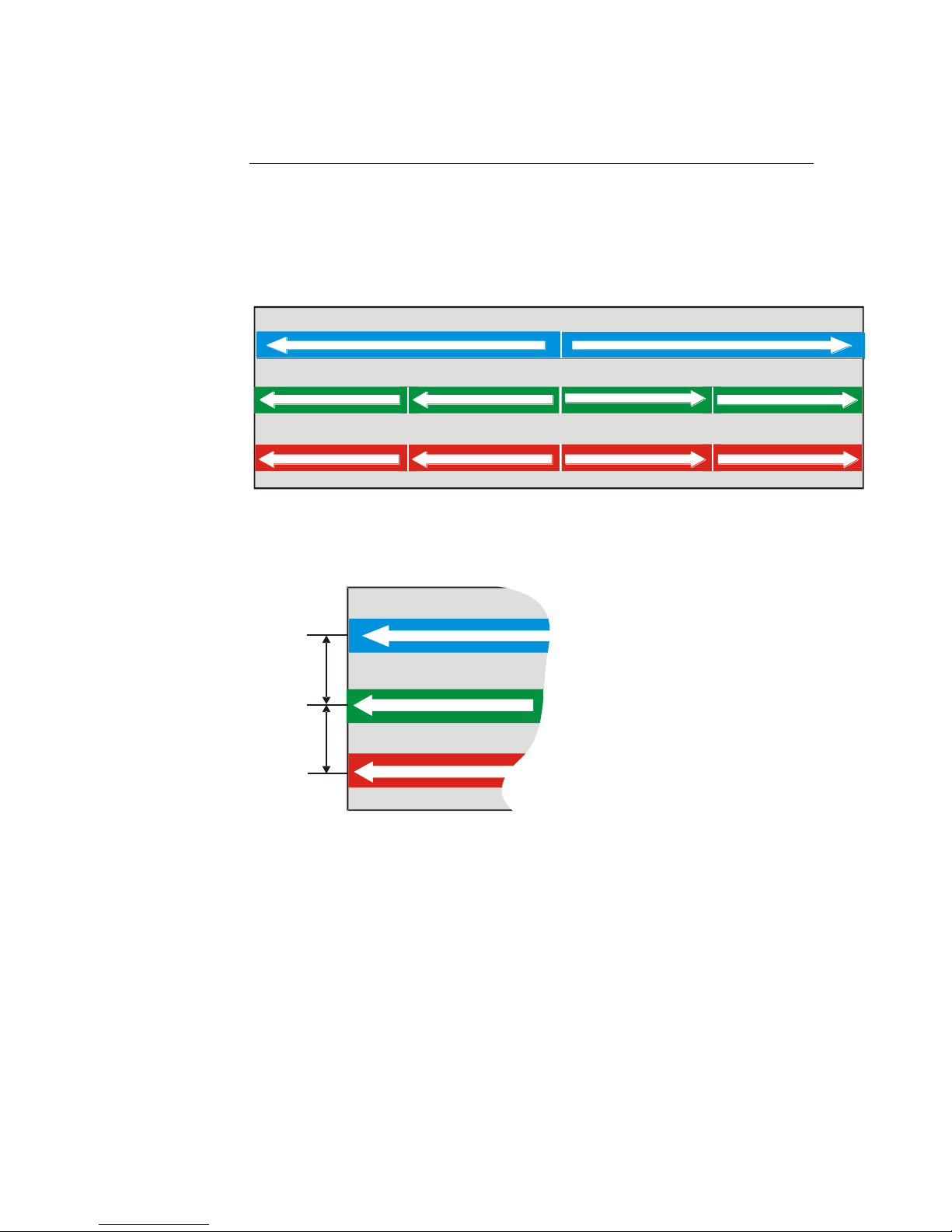
1.2 Image Sensor
The Piranha Color camera uses a trilinear CCD sensor with three lines of pixels: one
blue, one red and one green. Depending on your camera model, each line contains
either 2048 or 4096 pixels. As illustrated in the diagram below, the blue line has 2
outputs (taps), and the red and green lines have 4 outputs.
Figure 1: Sensor Block Diagram
Piranha Color Camera 12
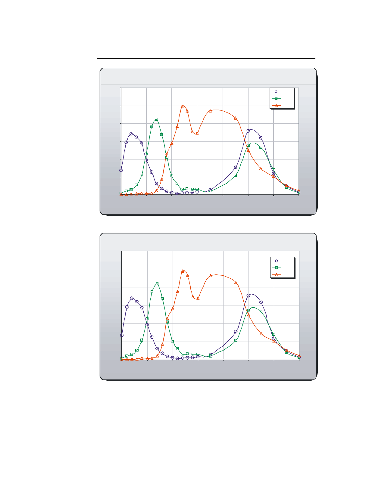
2K Spectral Responsivity, FFC on
0
10
20
30
40
50
60
400 500 600 700 800 900 1000 1100
Wavelength (nm)
Responsivity [DN/(nJ/cm
2
)]
Blue
Green
Red
4K Spectral Responsivity, FFC on
0
5
10
15
20
25
30
400 500 600 700 800 900 1000 1100
Wavelength (nm)
Responsivity[DN/(nJ/cm2)]
Blue
Green
Red
1.3 Responsivity
Piranha Color Camera 13
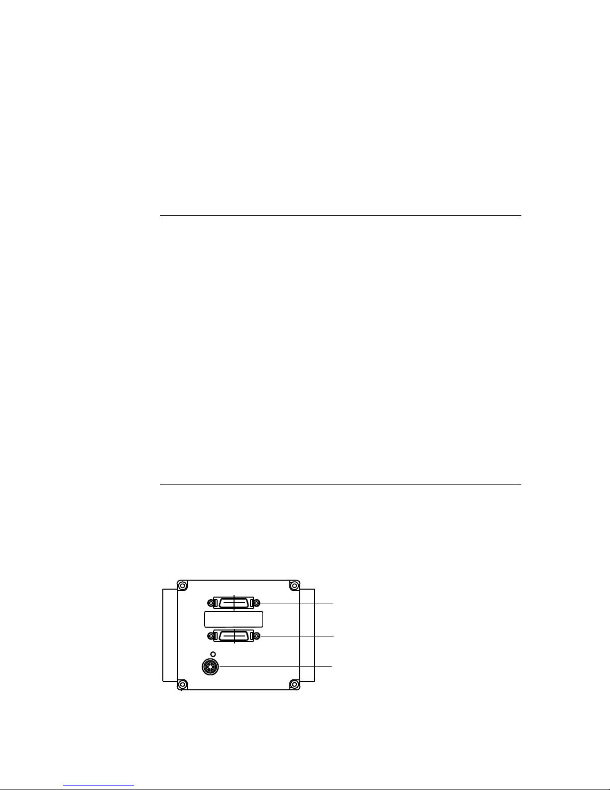
Camera Link Connector
Camera Link Connector
Power Connector
Hardware Interface: Connectors
and Timing
2.1 Installation Overview
When installing your camera, you should take these steps:
1. Power down all equipment.
2. Following the manufacturer’s instructions, install the frame grabber (if applicable).
Be sure to observe all static precautions.
3. Install any necessary imaging software.
4. Before connecting power to the camera, test all power supplies. Ensure that all the
correct voltages are present at the camera end of the power cable. Power supplies
must meet the requirements defined in section 2.2.2 Power Connector.
5. Inspect all cables and connectors prior to installation. Do not use damaged cables
or connectors or the camera may be damaged.
6. Connect Camera Link and power cables.
7. After connecting cables, apply power to the camera.
8. Check the diagnostic LED. See the LED Status Indicator section below for an
LED description.
9. The camera powers on with a baud rate of 9600.
You must also set up the other components of your system, including light sources,
camera mounts, host computers, optics, encoders, and so on.
2.2 Input / Output Connectors and LED
The camera uses:
An LED to display the camera's status.
High-density 26-pin MDR26 connectors for Camera Link control signals, data
signals, and serial communications.
One 6-pin Hirose connector for power.

Piranha Color Camera 14
!
Priority
Color of Status LED
Meaning
1
Flashing Red
Fatal Error. For example, camera temperature is too
high and camera thermal shutdown has occurred.
2
Flashing Green
Camera initialization or executing a long command
(e.g., flat field correction commands ccp or ccf).
During this state, any other sent command is ignored.
3
Solid Green
Camera is operational and functioning correctly and
ready to receive commands.
Hirose 6-pin Circular Male
5
4
6
2
3
1
Mating Part: HIROSE
HR10A-7P-6S
Table 2: Hirose Pin Description
Pin
Description
Pin
Description
1
Min +12 to Max +15V
4
GND
2
Min +12 to Max +15V
5
GND
3
Min +12 to Max +15V
6
GND
Note: Refer to the following sections for details on equipment recommendations and
camera connector information.
2.3 Camera LED
The camera is equipped with a red/green LED used to display the operational status of
the camera. The table below summarizes the operating states of the camera and the
corresponding LED states.
When more than one condition is active, the LED indicates the condition with the
highest priority. The fatal error state is accompanied by corresponding messages further
describing the problem.
Table 1: Diagnostic LED
2.4 Power Connector
Figure 2: Hirose 6-pin Circular Male—Power Connector
The camera requires a single voltage input (+12 V to +15 V). The camera meets all
performance specifications using standard switching power supplies, although wellregulated linear supplies provide optimum performance.
WARNING: When setting up the camera’s power supplies follow these guidelines:
Ensure +12 V to +15 V at the camera power input (after the voltage drop across
the power cable. This may mean that the power supply will have to provide a
voltage greater than the required camera voltage. For example, to achieve +12 V at
the camera, the power supply may need to be +12.5 V or greater.
Protect the camera with a fast-blow fuse between power supply and camera.
Do not use the shield on a multi-conductor cable for ground.
Keep leads as short as possible to reduce voltage drop.
Use high-quality linear supplies to minimize noise.
Use an isolated type power supply to prevent LVDS common mode range
violation.
Note: Camera performance specifications are not guaranteed if your power supply
does not meet these requirements.
Piranha Color Camera 15
Clocking Signal
Indicates
LVAL (high)
Outputting valid line
DVAL (high)
Valid data (unused, tied high)
STROBE (rising edge)
Valid data
FVAL (high)
Outputting valid frame (unused, tied high)
IMPORTANT:
This camera’s
data should be
sampled on the
rising edge of
STROBE.
i
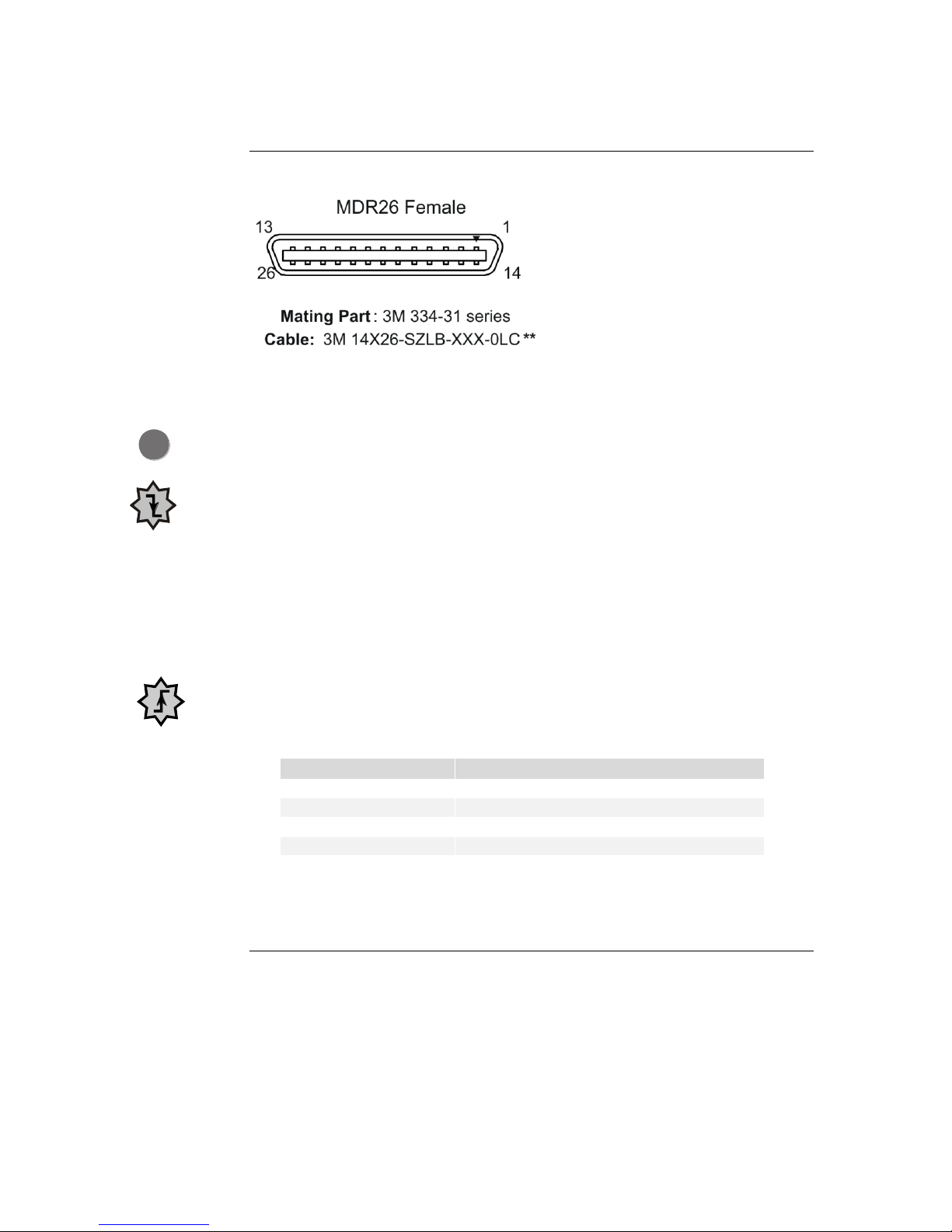
2.5 Camera Link Data Connector
Figure 3: Camera Link MDR26 Connector
Input Signals, Camera Link
The camera accepts control inputs through the Camera Link MDR26F connector.
The camera ships in internal sync, internal programmed integration (exposure mode 2).
EXSYNC (Triggers Line Readout)
Line rate can be set internally using the serial interface. The external control signal
EXSYNC is optional and enabled through the serial interface. This camera uses the
falling edge of EXSYNC to trigger pixel readout.
Direction Control
You control the CCD shift direction through the serial interface. With the software
command, scd, you determine whether the direction control is set via software control
or via the Camera Link control signal on CC3.
Output Signals, Camera Link
These signals indicate when data is valid, allowing you to clock the data from the camera
to your acquisition system. These signals are part of the Camera Link configuration and
you should refer to the Camera Link Roadmap, available from the Knowledge Center
on our website here, for the standard location of these signals.
The camera internally digitizes 12 bits and outputs the 8 MSB or all 12 bits
depending on the camera’s Camera Link operating mode.
2.6 Camera Timing
The Piranha Color camera uses a base or medium Camera Link interface.
Base Configuration
A base configuration uses 1 MDR26 connector and 1 Channel Link chip. The main
characteristics of the base configuration are:
Ports supported: A, B, C.
Piranha Color Camera 16
Base Configuration
One Channel Link Chip + Camera Control + Serial
Communication
Camera
Connector
Right Angle
Frame Grabber
Channel Link
Signal
1 1 inner shield
14
14
inner shield
2
25
X0-
15
12
X0+
3
24
X1-
16
11
X1+
4
23
X2-
17
10
X2+
5
22
Xclk-
18 9 Xclk+
6
21
X3-
19 8 X3+
7
20
SerTC+
20 7 SerTC-
8
19
SerTFG-
21 6 SerTFG+
9
18
CC1-
22 5 CC1+
10
17
CC2+
23 4 CC2-
11
16
CC3-
24 3 CC3+
12
15
CC4+
25 2 CC4-
13
13
inner shield
26
26
inner shield
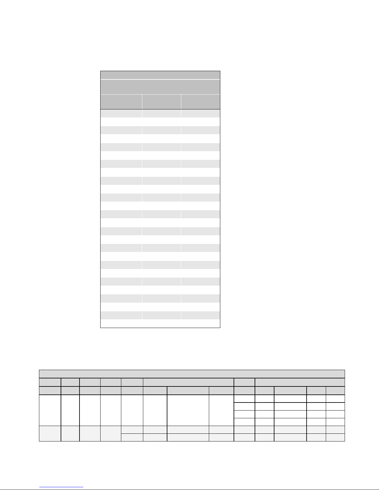
Base Configuration
Connector 1
Maximum SSF8
CLM1
Bits2
Taps3
Lum4
Time5
Port6 A
Port B
Port C
SOT7
2k60
4k60
2k80
4k80
5 8 1
No
NA
R
0-7
G
0-7
B
0-7
30
14.5
7.3
14.5
7.3
40
19.3
9.7
19.3
9.7
60
22.79
12.1
28.99
14.6
80
NA
NA
31.8
17.5
910 8 1
Yes
T0
R
0-7
B
0-7
NA
30
14.5
7.3
14.5
7.3
T1
G
0-7
Y
7-0
NA
40
19.3
9.7
19.3
9.7
Serializer bit width: 28.
Number of chips: 1.
Number of MDR26 connectors: 1.
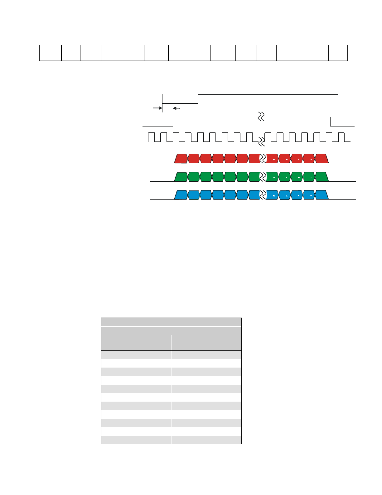
Base Configuration Timing
Each pixel output has 8 bits for each of the three colors (red, green, and blue).
Table 3: Base Configuration Video Data
Piranha Color Camera 17
1010
12 1 Yes
T0
R
0-7
B
8-11R8-11
B
0-7
30
14.5
7.3
14.5
7.3
T1
G
0-7
Y
8-11G8-11
Y
0-7
40
19.3
9.7
19.3
9.7
EXSYNC
TBD
R1
R2 R3 R4 R5 R6 R7
Rn 1
Rn
Rn 2
Rn 3
Rn 4
G1
Gn 1
Gn
Gn 2
Gn 3
Gn 4
G2
G3 G4 G5 G6 G7
B1
Bn 1
Bn Bn 2
Bn 3 Bn 4
B2
B3 B4
B5
B6 B7
RED Data
GREEN Data
BLUE Data
n = Number of pixels per line (2048 or 4096)
Data = 8 - bits/color/pixel
Line and Data Valid
Pixel Clock
40 or 80MHz
Medium Configuration (Connector 2)
2 Channel Link Chips
Camera
Connector
Right Angle
Frame Grabber
Channel Link
Signal
Cable Name
1 1 inner shield
Inner Shield
14
14
inner shield
Inner Shield
2
25
Y0-
PAIR1-
15
12
Y0+
PAIR1+
3
24
Y1-
PAIR2-
16
11
Y1+
PAIR2+
4
23
Y2-
PAIR3-
17
10
Y2+
PAIR3+
5
22
Yclk-
PAIR4-
18 9 Yclk+
PAIR4+
6
21
Y3-
PAIR5-
Figure 4: Base Configuration
Medium Configuration
A medium configuration uses 2 MDR26 connectors and 2 Channel Link chips. The
main characteristics of the medium configuration are:
Ports supported: A, B, C, D, E, F.
Serializer bit width: 28.
Number of chips: 2.
Number of MDR26 connectors: 2.

Piranha Color Camera 18
Medium Configuration (Connector 2)
2 Channel Link Chips
Camera
Connector
Right Angle
Frame Grabber
Channel Link
Signal
Cable Name
19 8 Y3+
PAIR5+
7
20
terminated
PAIR6+
20 7 terminated
PAIR6-
8
19
Z0-
PAIR7-
21 6 Z0+
PAIR7+
9
18
Z1-
PAIR8-
22 5 Z1+
PAIR8+
10
17
Z2-
PAIR9+
23 4 Z2+
PAIR9-
11
16
Zclk-
PAIR10-
24 3 Zclk+
PAIR10+
12
15
Z3-
PAIR11+
25 2 Z3+
PAIR11-
13
13
inner shield
Inner Shield
26
26
inner shield
Inner Shield
Notes:
*Exterior Overshield is connected to the shells of the connectors on both ends.
**3M part 14X26-SZLB-XXX-0LC is a complete cable assembly, including connectors.
Unused pairs should be terminated in 100 ohms at both ends of the cable.
Inner shield is connected to signal ground inside camera.
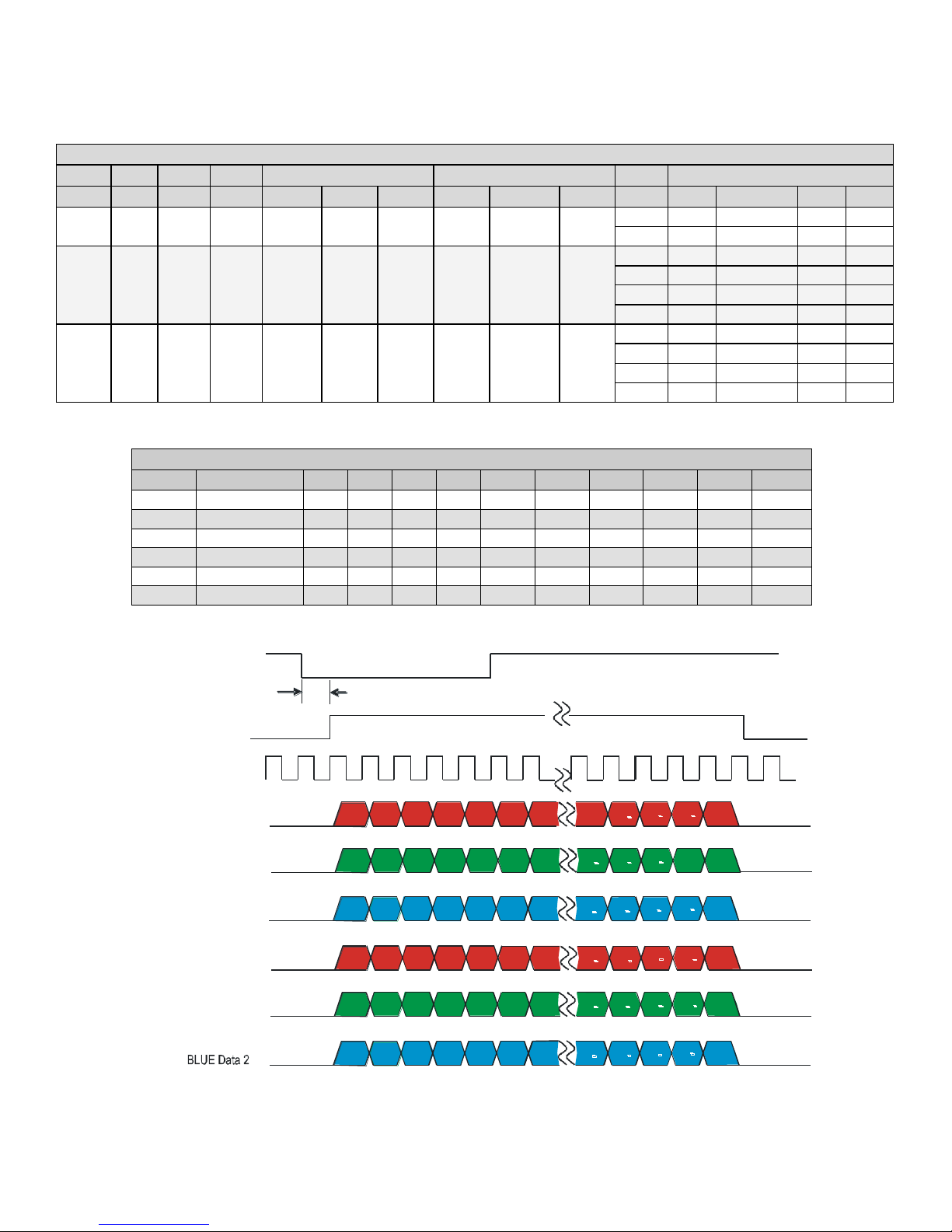
Piranha Color Camera 19
Medium Configuration
Connector 1
Connector 2
Maximum SSF8
CLM1
Bits2
Taps3
Lum4
Port6 A
Port B
Port C
Port D
Port E
Port F
SOT7
2k60
4k60
2k80
4k80
14 8 2
No
R
A
0-7
G
A
0-7
B
A
0-7
R
B
0-7
G
B
0-7
B
B
0-7
60
22.7
12.1
28.6
14.5
80
NA
NA
31.8
17.5
15 8 1
Yes
R
0-7
G
0-7
B
0-7
Y
0-7
NA
NA
30
14.5
7.3
14.5
7.3
40
19.3
9.7
19.3
9.7
60
22.7
12.1
28.9
14.6
80
NA
NA
31.8
17.5
16
12 1 Yes
R
0-7
B
8-11
R
8-11
B
0-7
Y
0-7
G
0-7
Y
8-11
G
8-11
30
14.5
7.2
14.5
7.3
40
19.3
9.7
19.3
9.7
60
22.7
12.1
28.9
14.6
80
NA
NA
31.8
17.5
CLM 14 Pixels are Interleaved
Port
Sequence
1 2 3 4 5 6 7 8 9
10
A
RedA
R1
R3
R5
R7
R9
R11
R13
R15
R17
R19
B
GreenA
G1
G3
G5
G7
G9
G11
G13
G15
G17
G19
C
BlueA
B1
B3
B5
B7
B9
B11
B13
B15
B17
B19 D RedB
R2
R4
R6
R8
R10
R12
R14
R16
R18
R20
E
GreenB
G2
G4
G6
G8
G10
G12
G14
G16
G18
G20
F
BlueB
B2
B4
B6
B8
B10
B12
B14
B16
B18
B20
EXSYNC
TBD
Line and Data Valid
Pixel Clock
40MHz
R1
R3
R5
R7 R9 R11
R13
Rn
1
Rn
Rn
3
Rn 5
Rn
- 7
G1
Gn - 1
Gn
Gn 3
Gn 5
Gn
7
G3
G5 G7
G9 G11
G13
B1
Bn
1
Bn
Bn
3
Bn
5
Bn
7
B3 B5
B7
B11
B13
RED Data 1
BLUE Data 1
GREEN Data 2
GREEN Data 1
G2
Gn
2
Gn Gn
4
Gn
6 Gn
8
G4
G6 G8
G10 G12
G14
RED Data 2
B2
Bn 2
Bn
Bn 4
Bn 6
Bn
8
B4 B6
B8
B10
B12
B14
R2
R4
R6
R8 R10 R12
R14
Rn
2
Rn
Rn
4
Rn
6
Rn
8
B9
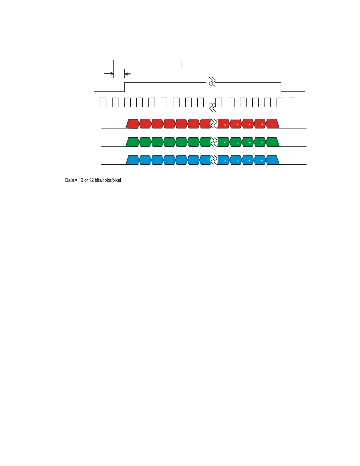
Medium Configuration Timing
Figure 5: Medium Configuration (8 Bits/Color/Pixel)
Piranha Color Camera 20
EXSYNC
TBD
R1
R2 R3 R4 R5 R6 R7
Rn 1
Rn
Rn 2
Rn 3
Rn 4
G1
Gn 1
Gn
Gn 2
Gn 3
Gn 4
G2
G3 G4 G5 G6 G7
B1
Bn 1
Bn Bn 2
Bn 3 Bn 4
B2
B3 B4
B5
B6
B7
RED Data
GREEN Data
BLUE Data
n = Number of pixels per line (2048 or 4096)
Line and Data Valid
Pixel Clock
40 or 80MHz
Figure 6: Medium Configuration (12 Bits/Color/Pixel)
Notes for Base and Medium Configuration Timing:
1. CLM: Camera Link Mode.
2. Bits: Number of bits per pixel.
3. Taps: Number of camera link taps per color.
4. Luminance: Indicates if a tap constructed from the RGB using the SCC command
is output.
5. Time: Time multiplex interval.
6. Port : Camera Link port.
7. SOT: Output throughput [mega-pixels / second / color].
8. Maximum SSF: Maximum line rate [kHz] possible in this mode (may be reduced by
SBH, ELS and SRM).
9. The maximum line rate for SOT 60 for the 80 model is greater than the 60 model as
a result of the different readout clocking scheme.
10. Time multiplexing (CLM 9 and 10) is not supported in all frame grabbers.
11. Measurements were made using command settings els 0 and srm 2.

Piranha Color Camera 21
Software Interface: Configuring
the Camera
Using ASCII Commands
All of the camera’s functionality is configurable through its serial interface using the
three-letter commands. You can use any terminal program (e.g. HyperTerminal) to send
serial commands to the camera; however, you must comply with the following serial
protocol:
8 data bits
1 stop bit
No parity
No flow control
9.6 kbps (at power up)
Camera does not echo characters
Command Format
When entering commands please remember the following:
A carriage return <CR> ends each command.
The camera will answer each command with either <CR><LF> OK > or
<CR><LF>Error xx: Error Message > or Warning xx: Warning
Message. The > character is always the last character sent by the camera.
The following parameter conventions are used in the manual:
i = integer value
f = real number
m = member of a set
s = string
t = tap id
x = pixel column number
y = pixel row number
Example: to return the current camera settings:
gcp <CR>
3.1 First Power Up Camera Settings
When the camera is powered up for the first time it operates using the following factory
settings:
Internal forward color scanning direction.
Maximum line rate: 32 kHz (2k) or 17 kHz (4k).
0 dB calibrated analog gain and offset.
Factory calibrated FPN and PRNU coefficients enabled.
8 bit output.

Piranha Color Camera 22
Purpose:
Sets the speed in bps of the serial communication port.
Syntax:
sbr m
Syntax Elements:
m
Baud rate. Available baud rates are: 9600 (Default), 19200,
57600, and 115200.
Notes:
Power-on rate is always 9600 baud.
The rc (reset camera) command will not reset the camera to the
power-on baud rate and will reboot using the last used baud rate.
Example:
sbr 57600
Purpose:
Sets the cable parameters.
Syntax:
scb m
Syntax Elements:
m
Output compare value. Available values are: 0 to 255.
Notes:
In medium configuration, both cables must be the same length.
Only one copy of this setting is saved in the camera (rather than
with each setting).
Using the lfs (load factory settings) command, the cable length
will be set to the factory default of 100.
The cable parameter is a relational value. Increase the value for
longer cables, and decrease it for shorter ones.
Adjust the value until the test pattern (svm 1) is clean.
Example:
scb 75
9600 baud rate.
Exposure mode 2: Internal sync and exposure control.
RGB color selection.
Camera Link mode 5: base configuration, RGB, 8 bit output.
Note: The FPN and PRNU coefficients are factory calibrated at 0 dB gain setting 0. The
FFC calibration line rate is 400 Hz.
3.2 Rebooting the Camera
The reset command (rc) reboots the camera. The camera starts up with the last saved
settings and baud rate used before reboot. Previously saved pixel coefficients are also
restored.
3.3 Baud Rate
3.4 Select Cable
3.5 Help
For quick help the camera can return all available commands and parameters through
the serial interface.

Piranha Color Camera 23
Syntax:
h
Syntax:
gh
Notes:
For more information on the camera’s ―get‖ commands, refer to
section Returning Camera Settings.
There are two different help screens available. One lists all of the available commands to
configure camera operation. The other help screen lists all of the commands available
for retrieving camera parameters (these are called ―get‖ commands).
To view the help screen listing all of the camera configuration commands, use the
command:
To view a help screen listing all of the ―get‖ commands, use the command:
The camera configuration command help screen lists all commands available. Parameter
ranges displayed are the extreme ranges available. Depending on the current camera
operating conditions, you may not be able to obtain these values. If this occurs, values
are clipped and the camera returns a warning message.
Some commands may not be available in your current operating mode. The help screen
displays NA in this case.
The following help screen listing is for a 2k camera:
ccf correction calibrate fpn
ccg calibrate camera gain iti 1-4:0-0:1024-4055
ccp correction calibrate prnu
cil calibrate input lut
clm camera link mode m 5/9/10/14/15/16/
cpa calibrate PRNU algorithm mi 1/2/3/4/:1024 4055
css correction set sample m 1024/2048/4096/
dil display input lut taa 0-0:0-1023:0-1023
dpc display pixel coeffs xx 1-2048:1-2048
ebc enable blue correction i 0-1
eil enable input lut i 0-1
els end of line sequence i 0-2
epc enable pixel coefficients ii 0-1:0-1
gcl get command log
gcm get camera model
gcp get camera parameters
gcs get camera serial
gcv get camera version
get get values s
gfc get fpn coeff x NA
gh get help
gil get input lut ta NA
gl get line xx 1-2048:1-2048
gla get line average xx 1-2048:1-2048
gpc get prnu coeff x NA
gsf get signal frequency i 1-4
h help
lfc load fpn coefficients
lfs load factory settings
lil load input lut
lpc load prnu coefficients
lus load user settings

Piranha Color Camera 24
Purpose:
Selects the forward or reverse color scan direction or external
direction control. This accommodates object direction change
on a web and allows you to mount the camera ―upside down.‖
Syntax:
scd i
Syntax Elements:
i
Shift direction. Allowable values are:
0 = Forward CCD shift direction.
rc reset camera
ril reset input lut
roi region of interest xx 1-2048:1-2048
rpc reset pixel coeffs
sab set add background ti 0-0:0-4095
sag set analog gain tf 0-0:-10.0-+10.0
sah set averaging horizontal i 1-2
sao set analog offset ti 0-0:0-255
sbr set baud rate m 9600/19200/57600/
115200/
scb select cable i 0-255
scc set colour correction iiii 0-+4095:-8192 +8191:-8192 +8191:-8192-+8191
scd set ccd direction i 0-2
scl set colour m rgb/r/g/b/
sdo set digital offset ti 0-0:0-4095
sem set exposure mode m 2/3/4/5/6/7/
sfc set fpn coeff xi NA
sfr set fpn range xxi NA
sil set input lut tai NA
slt set lower threshold i 0-4095
smm set mirroring mode i 0-1
sot set output throughput m 30/40/60/80/
spc set prnu coeff xi NA
spr set prnu range xxi NA
srm set readout mode i 0-2
ssa set spatial alignment i 0-6
ssb set subtract background ti 0-0:0-4095
ssf set sync frequency f 1-32362
ssg set system gain ti 0-0:0-65535
ssn set set number i 0-5
sut set upper threshold i 0-4095
svm set video mode i 0-10
ugr update gain reference
vt verify temperature
vv verify voltage
wfc write FPN coefficients
wil write input lut
wpc write PRNU coefficients
wus write user settings
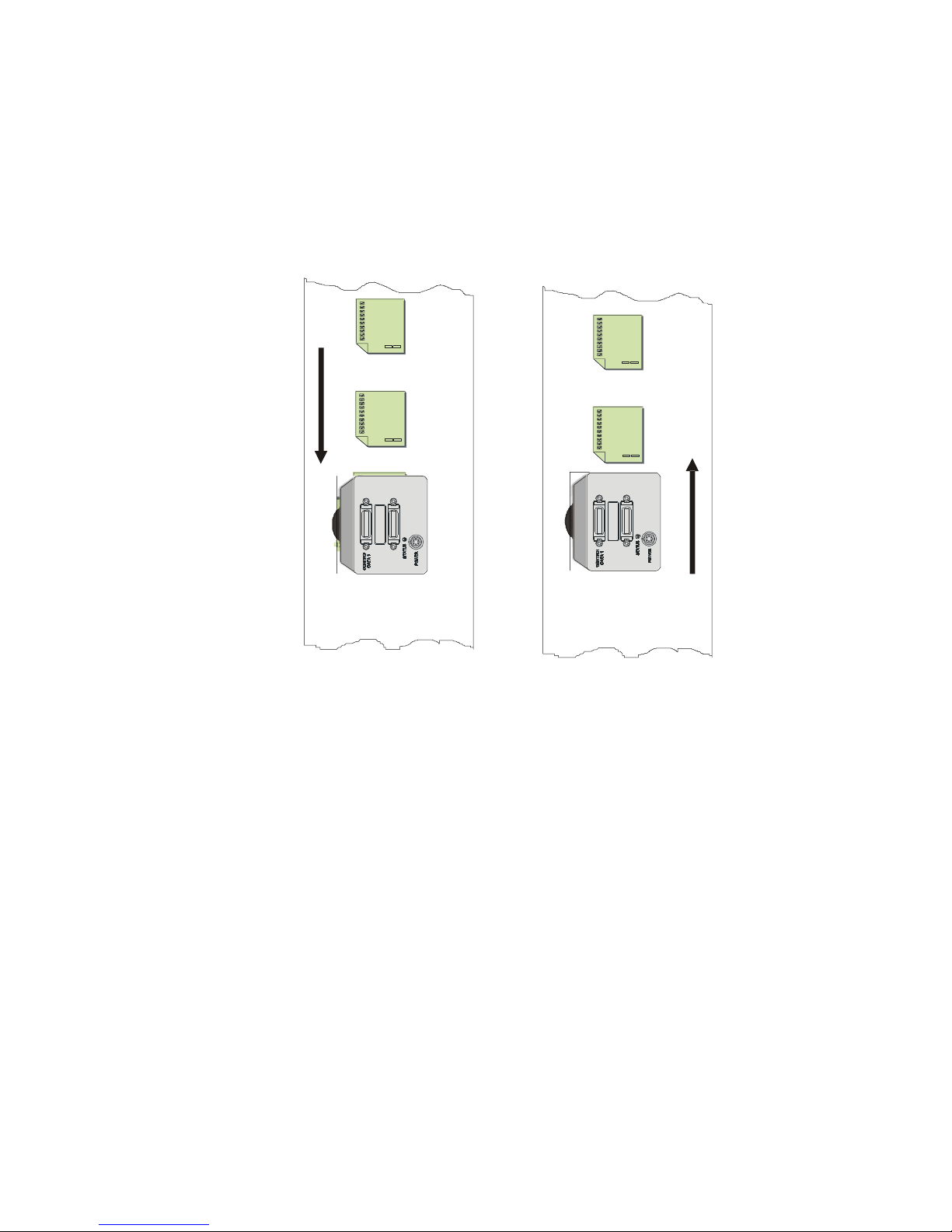
3.6 Sensor Output
Color Scan Direction
Piranha Color Camera 25
1 = Reverse CCD shift direction.
2 = External direction control via Camera Link control:
CC3 (CC3=1 forward, CC3=0 reverse).
Notes:
To obtain the current value of the shift direction, use the
command gcp or get scd.
Related Commands:
smm
Example:
scd 0
Direction of
Object Movement
Camera should operate in
Reverse CCD Shift Direction
scd 1
Direction of
Object Movement
Camera should operate in
Forward CCD Shift Direction
scd 0

Piranha Color Camera 26
Purpose:
Selects the camera’s horizontal readout direction.
Syntax:
smm i
Syntax Elements:
i
Direction of sensor readout
0 = Left to right = 1 to n
1 = Right to left = n to 1
Note:
Pixel readout remains the same after a direction change.
Example:
smm 0
Purpose:
Sets the camera’s Camera Link configuration, number of Camera
Link taps and data bit depth.
Syntax:
clm m
Syntax Elements:
m
5 = Base configuration, RGB, 8 bit output
9 = Base configuration, RGBY, 8 bit output
10 = Base configuration, RGBY, 12 bit output
14 = Medium configuration, 2xRGB, 8 bit output
15 = Medium configuration, RGBY, 8 bit output
16 = Medium configuration, RGBY, 12 bit output
Note:
To obtain the current data mode, use the command
gcp or get clm.
The bit patterns are defined by the Camera Link
Roadmap and the Camera Link Standard. Available
from the Knowledge Center on the Teledyne DALSA
site, here.
Example:
clm 5
Purpose:
The sot command works in conjunction with the clm
command (see previous command) and determines the pixel rate
of the camera.
Syntax:
sot m
Syntax Elements:
m
30 = outputs pixels RGB (triplet) or RGBY (quad) at 30
Mps
40 = outputs pixels RGB (triplet) or RGBY (quad) at 40
Mps
60 = outputs pixels RGB (triplet) or RGBY (quad) at 64
Mps
80 = outputs pixels RGB (triplet) or RGBY (quad) at 80
Mps
Sensor Readout Direction (Mirroring Mode)
3.7 Data Output
Setting the Camera Link Mode
Setting the Camera’s Pixel Rate (Throughput)

Piranha Color Camera 27
Note:
To obtain the current throughput, use the command
gcp or get sot.
The bit patterns are defined by the Camera Link
Roadmap and the Camera Link Standard. Available
from the Knowledge Center on the Teledyne DALSA
site, here.
Changes to the clm may affect this parameter.
Example:
sot 80
Purpose:
Sets the color correction coefficients.
Syntax:
scc Co C1 C2 C3
Syntax Elements:
Co = offset (0 to 4095)
C1 = red multiplier (-8192 to +8191)
C2 = green multiplier (-8192 to +8191)
C3 = blue multiplier (-8192 to +8191)
Note:
Set coefficients used to combine three color streams, e.g.
White = C0 + (C1 x Red) + (C2 x Green) + (C3 x Blue)
C0 is a DN, whereas:
Coefficient = C
1-3
/ 4,096
Modified by set color command (SCL):
RGB: White
R|G|B: Red, Green, or Blue
All colors are not necessary because constructing white is
different
Factory (initial) values combine the three colors equally:
White = 0 + (0.33 x Red) + (0.33 x Green) + (0.33 x Blue)
Cn = 0.33 x 4,096= 1,365
Red = 0 + (1 x Red) + (0 x Green) + (0 x Blue)
C1 = 1 x 4,096= 4,096
Range of {-8,192 to +8,191} is equivalent to floating point
coefficients of {-2.0 to +1.999}
Step size is 0.000244
Values are saved with camera settings
Values may be viewed with GCP or GET SCC
Example:
White = 100 + (0.25 x Red) + (-0.15 x Green) + (0.8 x Blue)
Therefore,
C1 = 0.25 x 4096 = 1024
C2 = (-0.15 x 4096) = -614
C3 = 0.8 x 4096 = 3276
OK>scl RGB
OK>scc 100 1024 -614 3276
3.8 Set Color Correction

Piranha Color Camera 28
Purpose:
Selects the color or colors that you want to adjust with the ccf,
ccg, ccp, cpa, dpc, gfc, gl, gla, gpc, sag, sao, sdo,
set, sfc, spc, ssb, ssg commands.
Syntax:
scl s
Syntax Elements:
s
rgb = adjust all colors (red, green, and blue). Power on
setting.
r = adjust red
g = adjust green
b = adjust blue
Note:
The camera always powers up using scl rgb.
Example:
scl b
Color selection limits the taps that can be selected in these commands as follows:
scl
Tap
Notes
rgb
0
All 10 camera taps
r
0
1 to 4
All 4 red taps
Single red tap
g
0
1 to 4
All green taps
Single green tap
b
0
1 to 2
All blue taps (2)
Single blue tap
Purpose:
When saving and loading camera settings, you have a choice of
saving up to four different sets and loading from five different
sets (four user and one factory). This command determines the
set number from where these values are loaded and saved. The
set number is saved along with the camera settings when the
wus command is issued.
Syntax:
ssn i
Syntax Elements:
i
0 = Factory set. Settings can only be loaded from this set.
1 - 4 = User sets. You can save, or load settings with these
sets.
Note:
The camera powers up with the last set saved using this
command.
Related Commands
wus, lus, wil, lil, wfc, lfc
3.9 Camera Selection Variables
There are some camera condition variables that you should determine before adjusting
any digital or analog settings like gain or offset, or before changing the camera’s
exposure time. These variables are:
The color (or colors) that you want to adjust.
The set number where you want to save any of these adjustments.
The region of interest for performing these adjustments.
Setting the Color Variable
Selecting the Set Number

Piranha Color Camera 29
Example:
ssn 3
Purpose:
Sets the pixel range used to collect the end-of-line statistics and
sets the region of pixels used in the ccg, gl, gla, ccf, and
ccp commands.
In most applications, the field of view exceeds the required object
size and these extraneous areas should be ignored. It is
recommended that you set the region of interest a few pixels
inside the actual useable image.
Syntax:
roi x1 x2
Syntax Elements:
x1
Column start number. Must be less than the pixel end number
in a range from 1 to sensor resolution.
x2
Column end. Must be greater than the pixel start number in a
range from 1 to sensor resolution.
Notes:
To return the current region of interest, use the commands gcp
or get roi.
Related Commands
ccg, gl, gla, ccf, ccp, cpa, els
Example:
roi 10 50
You must first set the camera exposure mode using the sem command.
Next, if using mode 2 or 7 use the commands ssf and set to set the line rate and exposure
time.
Purpose:
Sets the camera’s exposure mode allowing you to control your sync,
exposure time, and line rate generation.
Syntax:
sem i
Syntax Elements:
i
Exposure mode to use. Factory setting is 2.
Notes:
Refer to Table 4: Color Exposure Modes for a quick list of available
modes or to the following sections for a more detailed explanation.
To obtain the current value of the exposure mode, use the command
gcp or get sem.
Related Commands:
ssf, set
Example:
sem 3
Setting a Region of Interest (ROI)
3.10 Exposure Control
Overview
You have a choice of operating in one of six exposure modes. The camera’s line rate
(synchronization) can be generated internally through the software command ssf or set
externally with an EXSYNC signal, depending on your mode of operation. To select
how you want the camera’s line rate to be generated:
Setting the Exposure Mode
 Loading...