

03-032-20180-01
www.teledynedalsa.com
Piranha 4 Color
P4-CC-04K07T-00-R Camera User’s Manual

2 Piranha4 4K Camera Color User's Manual
North America
700 Technology Park Drive
Billerica, MA
USA, 01821
Tel: 978-670-2000
Fax: 978-670-2010
Email: Sales.Americas@teledynedalsa.com
Europe
Felix-Wankel-Str. 1
82152 Krailling
Germany
Tel: +49 89 89 54 57 3-80
Fax: +49 89 89 54 57 3-46
Email: Sales.Europe@teledyned alsa.com
Asia Pacific
Ikebukuro East 13F
3-4-3 Higashi Ikebukuro, Toshima-ku,
Tokyo, Japan
Tel: +81 3 5960 6353
Fax: +81 3 5960 6354
Email: Sales.Asia@teledynedalsa.com
© 2013 Teled yne DALSA, Inc. All information provided in this manual is believed to be accurate and reliable. No responsibility is
assumed by Teledyne DALSA for its use. Teledyne DALSA reserves the right to make changes to this information without notice.
Reproduction of this manual in whole or in part, by any means, is prohibited without prior permission having been obtained from
Teled yne DALSA.
About Teledyne Technologies and Teledyne DALSA, Inc.
Teled yne Technologies is a leading provid er of sophisticated electronic subsystems, instrumentation and communication products,
engineered systems, aerospace engines, and energy and pow er generation systems. Teledyne Tech nologies‘ op erat ion s a re prim a rily
located in the Unit ed Sta tes, th e United Kingd om an d Mexico. For m ore in form ation, visit Teled yn e Techno log ies‘ w eb sit e at
www.teledyne.com.
Teled yne DALSA, a Teledyne Technologies company, is an international leader in high performance digital imaging and
semiconductors with approximately 1,000 employees worldwide, headquartered in Waterloo, Ontario, Canada. Established in 1980,
the company designs, develops, manufactures and markets digital imaging products and solutions, in addition to providing MEMS
products an d serv ices. For mo re information , visit Teled yne DA LSA‘s w ebsite at www.teledynedalsa.com.
Support
For further information not includ ed in this manual, or for information on Teledyne DALSA‘s extensive lin e o f im age sensin g
products, please contact:
03-032-20180-01 Teledyne DALSA

Piranha4 4K Color Camera User's Manual 3
Contents
System Precautions ............................................................................................................................................................ 6
Precautions ..................................................................................................................................................... 6
Electrostatic Discharge and the CMOS Sensor ................................................................................................. 6
1. The Piranha4 Color Camera _______________________________________________________________________ 7
Camera Highlights ............................................................................................................................................................. 7
Camera Performance Specifications .................................................................................................................................. 8
Certifications ...................................................................................................................................................................... 9
Supported Industry Standards ........................................................................................................................................... 9
Sensor Responsivity and Design ........................................................................................................................................ 10
Responsivity .................................................................................................................................................... 10
Spatial Correction and Trilinear Sensor Design ............................................................................................. 12
Camera Direction ............................................................................................................................................ 15
Mechanicals ........................................................................................................................................................................ 16
Camera Mounting and Heat Sink Considerations ........................................................................................... 18
Filters .............................................................................................................................................................. 18
2. Quick, Simple Steps to Acquire an Image ______________________________________________________________ 19
3. Software and Hardware Setup______________________________________________________________________ 20
Recommended System Requirements ............................................................................................................. 20
Setup Steps: Overview ....................................................................................................................................................... 20
1. Install and Configure Frame Grabber and Software .................................................................................. 20
2. Connect Camera Link and Power Cables .................................................................................................... 20
3. Establish communicating with the camera .................................................................................................. 20
4. Operate the Camera ................................................................................................................................... 20
Step 1. Install and configure the frame grabber and software ........................................................................................ 21
Install Frame Grabber .................................................................................................................................... 21
Install Sapera LT and CamExpert GUI ............................................................................................................ 21
Step 2. Connect Data, Trigger, and Power Cables ............................................................................................................. 22
Data Connector: Camera Link ........................................................................................................................ 23
Camera Link Bit Definitions ............................................................................................................................ 23
Camera Timing .................................................................................................................................................................. 24
Camera Link cable quality and length ............................................................................................................ 30
Input Signals, Camera Link ............................................................................................................................ 30
Output Signals, Camera Link Clocking Signals............................................................................................... 31
Power Connector ............................................................................................................................................. 31
LEDs ................................................................................................................................................................ 32
Step 3. Establish Communication with the Camera ........................................................................................................... 32
Power on the camera ...................................................................................................................................... 32
Connect to the frame grabber ......................................................................................................................... 32
Connect to the camera .................................................................................................................................... 32
Check LED Status ............................................................................................................................................ 33
Software Interface ........................................................................................................................................... 33
Using Sapera CamExpert with Piranha4 Cameras ............................................................................................................ 34
Teledyne DALSA 03-032-20180-01

4 Piranha4 4K Camera Color User's Manual
CamExpert Panes ............................................................................................................................................ 35
Review a Test Image ....................................................................................................................................... 37
4. Camera Operation ______________________________________________________________________________ 38
Factory Settings ................................................................................................................................................................. 38
Check Camera and Sensor Information ............................................................................................................................. 38
Verify Temperature and Voltage ....................................................................................................................................... 39
Saving and Restoring Camera Settings ............................................................................................................................. 40
Camera Link Configuration ............................................................................................................................................... 42
Trigger Modes .................................................................................................................................................................... 42
Exposure Controls .............................................................................................................................................................. 42
Exposure Modes in Detail .................................................................................................................................................. 44
Set Line Rate ..................................................................................................................................................................... 46
Set Exposure Time ............................................................................................................................................................. 50
Control Gain and Black Level ............................................................................................................................................ 50
Set Image Size ................................................................................................................................................................... 50
Set Baud Rate .................................................................................................................................................................... 51
Pixel Format ...................................................................................................................................................................... 51
Camera Direction Control .................................................................................................................................................. 52
Pixel Readout Direction (Mirroring Mode) ........................................................................................................................ 52
Resetting the Camera ........................................................................................................................................................ 52
Calibrating the Camera ..................................................................................................................................................... 53
Appendix A: GenICam Commands _____________________________________________________________________ 57
Camera Information Category ........................................................................................................................................... 57
Camera Information Feature Descriptions...................................................................................................... 58
Camera Configuration Selection Dialog ......................................................................................................... 61
Camera Power-up Configuration .................................................................................................................... 61
User Set Configuration Management ............................................................................................................. 61
Camera Control Category .................................................................................................................................................. 62
Camera Control Feature Descriptions ............................................................................................................. 63
Independent Exposure Control .......................................................................................................................................... 65
Digital I/O Control Feature Descriptions ........................................................................................................ 67
Flat Field Category ............................................................................................................................................................ 68
Flat Field Control Feature Description ............................................................................................................ 68
Region of Interest (ROI) .................................................................................................................................. 70
Image Format Control Category ........................................................................................................................................ 70
Image Format Control Feature Description .................................................................................................... 71
Area of Interest (AOI) Setup .............................................................................................................................................. 72
Instructions on using the camera scan direction to control camera parameters ................................................................ 75
Transport Layer Control Category ..................................................................................................................................... 78
Transport Layer Feature Descriptions ............................................................................................................. 79
Acquisition and Transfer Control Category ........................................................................................................................ 80
Acquisition and Transfer Control Feature Descriptions................................................................................... 80
Serial Port Control Category .............................................................................................................................................. 81
Serial Port Control Feature Descriptions ........................................................................................................ 81
File Access Control Category .............................................................................................................................................. 82
03-032-20180-01 Teledyne DALSA

Piranha4 4K Color Camera User's Manual 5
File Access Control Feature Descriptions ......................................................................................................... 83
File Access via the CamExpert Tool ................................................................................................................. 84
Download a List of Camera Parameters ......................................................................................................... 85
Appendix B: ASCII Commands _______________________________________________________________________ 87
Port Configuration .......................................................................................................................................... 88
Commands ...................................................................................................................................................... 89
Appendix C: Quick Setup and Image Acquisition ___________________________________________________________ 101
Appendix D: The Sensor Window _____________________________________________________________________ 104
Cleaning and Protecting Against Dust, Oil, and Scratches .............................................................................. 104
Cleaning the Sensor Window .......................................................................................................................... 105
Appendix E. Color Deca and Full Mode Acquisition _________________________________________________________ 106
Overview ............................................................................................................................................................................ 106
Supported Sapera LT ...................................................................................................................................... 106
Programming Deca Mode.................................................................................................................................................. 106
A simple workaround accomplishes this ......................................................................................................... 107
Sample Code ................................................................................................................................................... 108
Programming Full Mode ................................................................................................................................................... 108
A simple workaround accomplishes this ......................................................................................................... 109
Sample Code ................................................................................................................................................... 110
Appendix F: Camera, Frame Grabber Communication _______________________________________________________ 111
Setting Up Communication between the Camera and the Frame Grabber .................................................... 111
EMC Declaration _________________________________________________________________________________ 113
Revision History _________________________________________________________________________________ 114
Index ________________________________________________________________________________________ 115
Teledyne DALSA 03-032-20180-01

6 Piranha4 4K Camera Color User's Manual
System Precautions
Precautions
Read these precautions and this manual carefully before using the camera.
Confirm that the camer a‘s p ackagin g is u nd am aged befor e op enin g it. If th e p ackagin g is da maged please
contact the relevant logistics personnel.
Do not open the housing of the camera. The warranty is voided if the housing is opened.
Keep the camera housing temperature in a range of 0 °C to 65 °C during operation.
Do not operate the camera in the vicinity of strong electromagnetic fields. In addition, avoid electrostatic
charging, violent vibration, and excess moisture.
To clean the device, avoid electrostatic charging by using a dry, clean absorbent cotton cloth dampened
with a small quantity of pure alcohol. Do not use methylated alcohol. To clean the surface of the camera
housing, use a soft, dry cloth. To remove severe stains use a soft cloth dampened with a small quantity of
neutral detergent and then wipe dry. Do not use volatile solvents such as benzene and thinners, as they
can damage the surface finish. Further cleaning instructions are below.
Though this camera supports hot plugging, it is recommended that you p ower down and disconnect
power to the camera before you add or replace system components.
Electrostatic Discharge and the CMOS Sensor
Image sensors and the camera bodies housing are susceptible to damage from electrostatic discharge
(ESD). Electrostatic charge introduced to the sensor window surface can induce charge buildup o n the
underside of the window that cannot be readily dissipated by the dry nitrogen gas in the sensor package
cavity. The charge normally dissipates within 24 hours and the sensor returns to normal operation.
Additional information on cleaning the sensor window and protecting it against dust, oil, blemishes, and
scratches can be found here, Appendix D: The Sensor Window.
03-032-20180-01 Teledyne DALSA

Piranha4 4K Color Camera User's Manual 7
1. The Piranha4 Color Camera
Camera Highlights
Based on Teledyne DALSA's unique CMOS color line scan sensor architecture, the new Piranha4 4k
Trilinear color camera provides outstanding signal-to-noise performance for high speed imaging. The P44k has 4k resolution with a 10 µm x 10 µm pixel size for optimized optical design. The camera delivers a
maximum line rate of 70 kHz.
Precise sensor alignment simplifies multiple camera calibration at the system level. GenICam ™ or ASCII
command-compliant interfaces make the camera easier to setup, control, and integrate. Programmable
features include exposure control, flat field correction, and gain settings.
The Piranha4 4k camera is ideal for printing inspection, printed circuit board, solar cell, film, and large
format web inspection.
Key Features
CMOS color trilinear line scan
4k pixel resolution
Line rates up to 70 kHz
Exposure control
100x antiblooming
RGB outputs
Camera Link interface
GenICam or ASCII command-compliant interfaces
Programmability
Save up to eight sets of correction coefficients
Adjustable gain and offset
White balance and color correction
Lens and shading correction with defocusing capability
Test pattern and diagnostics
Multi-AOI output allows faster line rates
Applications
Printing inspection
High performance document scanning
Electronics
Film inspection
High throughput applications
Teledyne DALSA 03-032-20180-01

8 Piranha4 4K Camera Color User's Manual
Model Number
Description
P4-CC-04K07T-00-R
4k resolution, 70 kHz line rate, Camera Link interface.
Software
Product Number / Version Number
Camera firmware
Embedded within camera
GenICam™ support (XML camera description file)
Embedded within camera
Sapera LT, including CamExpert GUI application and
GenICam for Camera Link imaging driver
Version 7.2 or later
Specifications
Performance
Imager Format
CMOS trilinear color line scan
Resolution
4096 x 3 pixel lines*
Pixel Size
10.56 µm x 10.56 µm
Full Well Capacity
20 ke- @ minimum gain of 1x
Line Rate
0 kHz minimum to 70 kHz maximum (Deca RGB8)
Exposure Time
7 µs minimum to 3,000 µs maximum
Bit Depth
8, 10, and 12 bits
Connectors and Mechanicals
Control & Data Interface
2 SDR26 Camera Link connectors used to transmit Base, Medium, Full, or
Deca configurations
Power Connector
Hirose 6-pin circular
Power Supply
+ 12 V to + 24 V DC
Maximum Current Draw
12 W/ (Applied voltage at camera connector)
Power Dissipation
12 W
Size
62 mm (W) x 62 mm (H) x 48 mm (D)
Mass
< 340 g (without heat sinks)
Operating Temp
0 °C to 65 °C, front plate temperature
Optical Interface
Lens Mount
M58 x 0.75
F-mount adapter available
Sensor to Camera Front Distance
12 mm
Sensor Alignment (aligned to sides of camera)
Flatness
y (parallelism)
x
y
z
z
50 µm
0.08° or 81 µm
± 100 µm
± 100 µm
± 250 µm
± 0.2°
Models
The camera is available in the following configurations:
Table 1: Camera Models Overview
Table 2: Software
Camera Performance Specifications
Table 3: Camera Performance Specifications
03-032-20180-01 Teledyne DALSA

Piranha4 4K Color Camera User's Manual 9
Compliance
Regulatory Compliance
CE and RoHS, GenICam
Operating Ranges
Performance
Red
Green
Blue
Dynamic Range
61.8 dB
61.8 dB
61.8 dB
Random Noise
3.25 DN** rms
3.25 DN rms
3.25 DN rms
Responsivity
Refer to graph
Gain
1x to 10x Nominal Range (not includ ing individual RGB gains for white balance)
DC Offset
< 11 DN
< 11 DN
< 11 DN
PRNU
< 2% @50% Sat
< 2% @50% Sat
< 2% @50% Sat
FPN
< 6.3 DN
< 6.3 DN
< 6.3 DN
SEE
7.8 nJ / cm2
9.6 nJ / cm2
9.5 nJ / cm2
NEE
6.3 pJ / cm2
7.8 pJ / cm2
7.7 pJ / cm2
Antiblooming
> 100 x Saturation
Integral non-linearity
< 2% DN
Compliance
EN 55011, FCC Part 15, CISPR 11, and ICES-003 Class A Radiated Emissions Requirements*
EN 55024, and EN 61326-1 Immunity to Disturbance*
RoHS per EU Directive 2002/ 95/ EC and WEEE per EU Directive 2002/ 96/ EC and China Electronic Industry
Standard SJ/ T11364-2006*
GenICam XML Description File, Superset of the GenICam™ Stan d ard Features N am in g Con ven tion specification
V1.5, Camera Link Serial Comm u n ication: Gen ICam ™ Generic Control Protocol (GenCP V1.0)
*Note: The P4-CC-04K07T-00-R camera has been designed to output 4096 pixels of RGB data. However,
due to a limitation of the sensor, the output is limited to 4080 pixels for the camera‘s initial release. This
restriction will be resolved in a future release. Details of when the full 4096 pixel cameras will be available
can be obtained from your Teledyne DALSA Key Account Manager.
**DN = digital number
Test Conditions:
Values measured using 12-bit, 1x gain.
10 kHz line rate
Light source: white LED
No white balancing
Front plate temperature: 45º C
Certifications
* Pending test results.
Supported Industry Standards
GenICam™
Piranha4 cameras are GenICam compliant. They imp lem ent a sup erset of th e GenICam ™ Stan d ar d
Features Naming Convention specification V1.5. This description takes the form of an XML device
descrip tion file resp ectin g the syn tax d efined by the Gen A p i mod u le of the Gen IC am ™ specification. The
camera uses the GenICam ™ Gen eric Contr ol Pr otocol (GenCP V1.0) to com m unicate ov er th e Cam era
Link serial port. For more information see www.genicam.org.
Teledyne DALSA 03-032-20180-01
10 Piranha4 4K Camera Color User's Manual
0
100
200
300
400
500
600
400 450 500 550 600 650 700 750 800 850 900
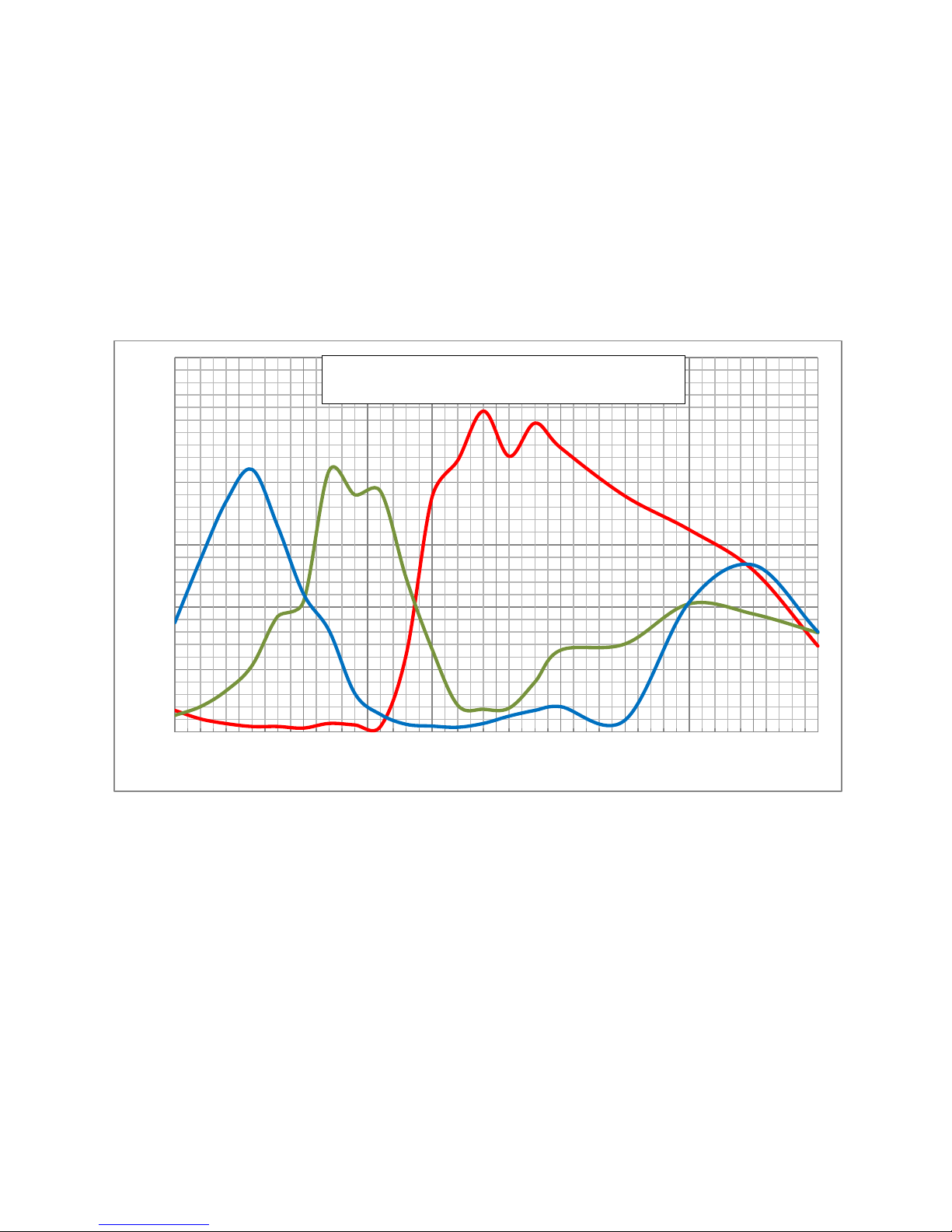
Spectral Responsivity (DN/nJ/cm^2)
Wavelength (nm)
P4 4k Trilinear Color Spectral Responsivity
No White Balance, 12 bit, gain 1x
Sensor Responsivity and Design
Responsivity
The responsivity graph illustrates the sensor‘s response to different wavelengths of light (excluding lens
and light source characteristics).
Note: The responsivity of a color camera will measure approximately 1/ 6th that of a similar monochrome
camera model as a result of the effect the color filter has on the sensor and also due to the color camera
not incorporating TDI Mode.
Figure 1: Spectral Responsivity
Filters
CMOS cameras are responsive to infrared (IR) wavelengths of light. Infrared light can be problematic
with halogen light sources but is not a issue with white LED sources. When infrared light is present with
this camera color fidelity is reduced. To prevent infrared from distorting the images you scan, use an IR
cut off filter such as a BG-38 on the lens.
03-032-20180-01 Teledyne DALSA

Piranha4 4K Color Camera User's Manual 11
[ADD GRAPH]
Figure 2: Calibration Source Relative Intensity vs. Wavelength
Teledyne DALSA 03-032-20180-00
12 Piranha4 4K Camera Color User's Manual
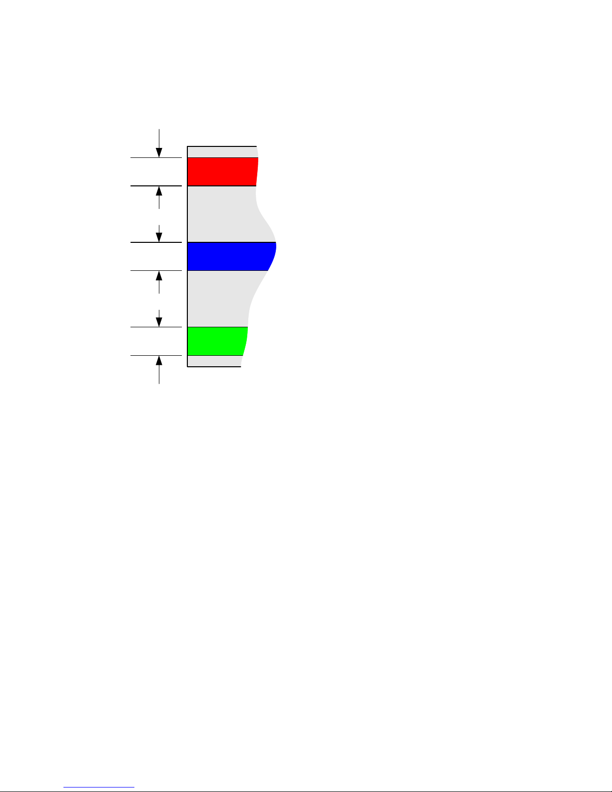
10.56um
10.56um
10.56um
21.12um
21.12um
Red
Blue
Green
Spatial Correction and Trilinear Sensor Design
The P4-CC-04K07T-00-R camera uses a trilinear sensor where three separate 4K lines of pixels are used—
one for red, the center for blue and the last for green.
Figure 3: Trilinear Sensor Line Spacing Diagram
The three lines of pixels are separated by single line spacing each and this line spacing is equal to 2x the
sensor pixel size. When the image passes the three lines of pixels, the red, blue and green components for
the same image location are captured at a different time as dictated by the line spacing. The camera
automatically corrects for the line spacing to ensure that the red, blue and green components of the image
pixel are all aligned when output. However, this is only correct when the object pixel size is square ; i.e.,
the distance moved by the object for one EXSYNC period is equal to the width of the object pixel. In some
applications it may not be possible to achieve a ‗square‘ object p ixel as fine ad justm ent of the lens
magnification and / or the distance moved for each EXSYNC period is not possible. This scenario may be
especially apparent when trying to integrate the camera into an existing system.
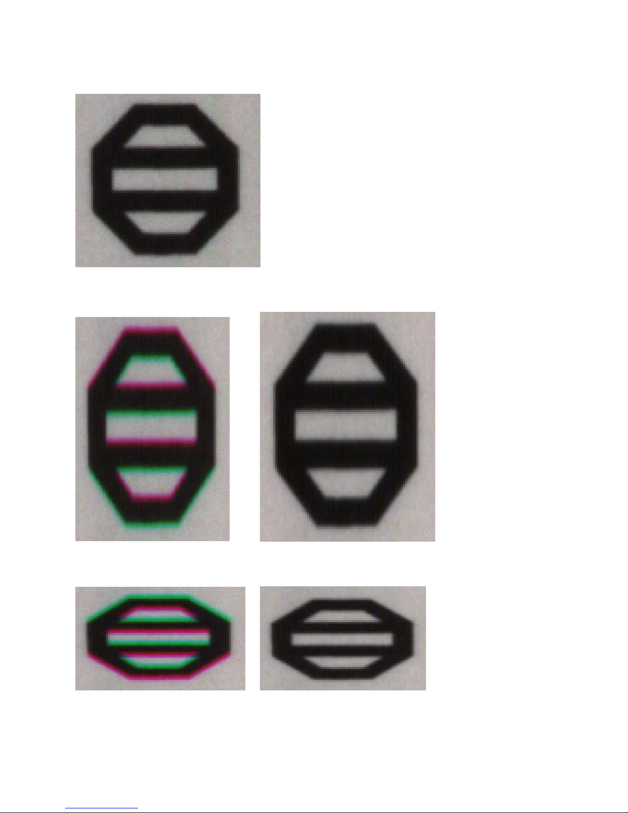
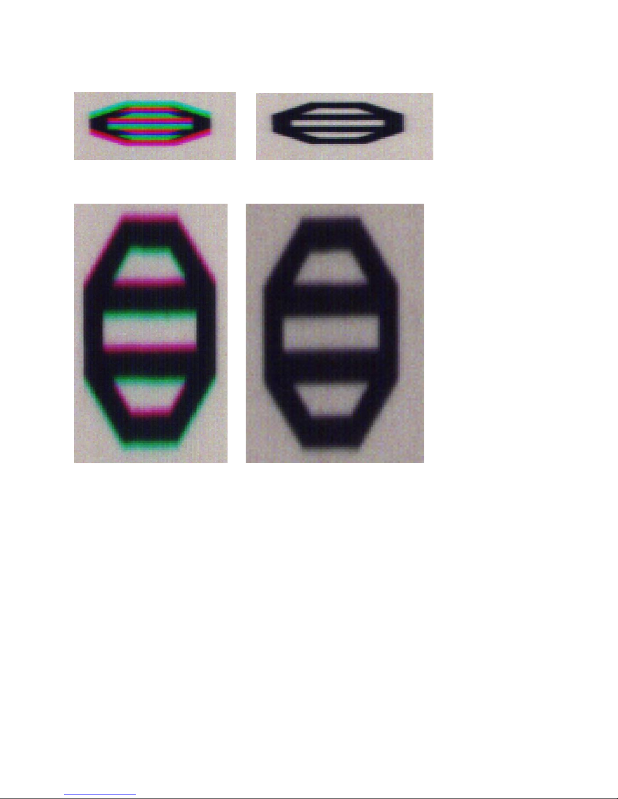
When it is not possible to generate a square object pixel, color artefacts will occur in the scan direction
and is particularly noticeable at sharp edge transitions. The size of the edge artefact is proportional to
how far the pixel is from square. To correct for this, the camera has a feature, Line Spatial Correction (or
three letter command ssa), which allows fine adjustment of the compensation mechanism the camera uses
to correct for the line spacing.
The default setting for this feature is 3, which is set for square object pixels. The setting can be adjusted
from 0 to 5 to compensate for rectangular pixels—whether they are too long or to short.
The following examples of image artefacts show black to white image transitions and the associated
corrected image after applying a specific ssa setting.
03-032-20180-01 Teledyne DALSA
Piranha4 4K Color Camera User's Manual 13
Example 1. Target speed adjusted for square pixels
Line Spatial Correction = 3 (ssa = 3). This is the default condition.
Example 2. Target running slower than example 1. same EXSYNC (trigger) frequency
Line Spatial Correction = 3 (ssa = 3) Line Spatial Correction = 4.3 (ssa = 4.3)
Example 3. Target running faster than example 1. same EXSYNC (trigger) frequency
Line Spatial Correction = 3 (ssa = 3) Line Spatial Correction = 1.73 (ssa = 1.73)
Teledyne DALSA 03-032-20180-01
14 Piranha4 4K Camera Color User's Manual
Example 4. Target running slower than EXSYNC
Line Spatial Correction = 3 (ssa = 3) Line Spatial Correction = 1 (ssa = 1)
Example 5. Target running faster than EXSYNC
Line Spatial Correction = 3 (ssa = 3) Line Spatial Correction = 5 (ssa = 5)
03-032-20180-01 Teledyne DALSA
Piranha4 4K Color Camera User's Manual 15
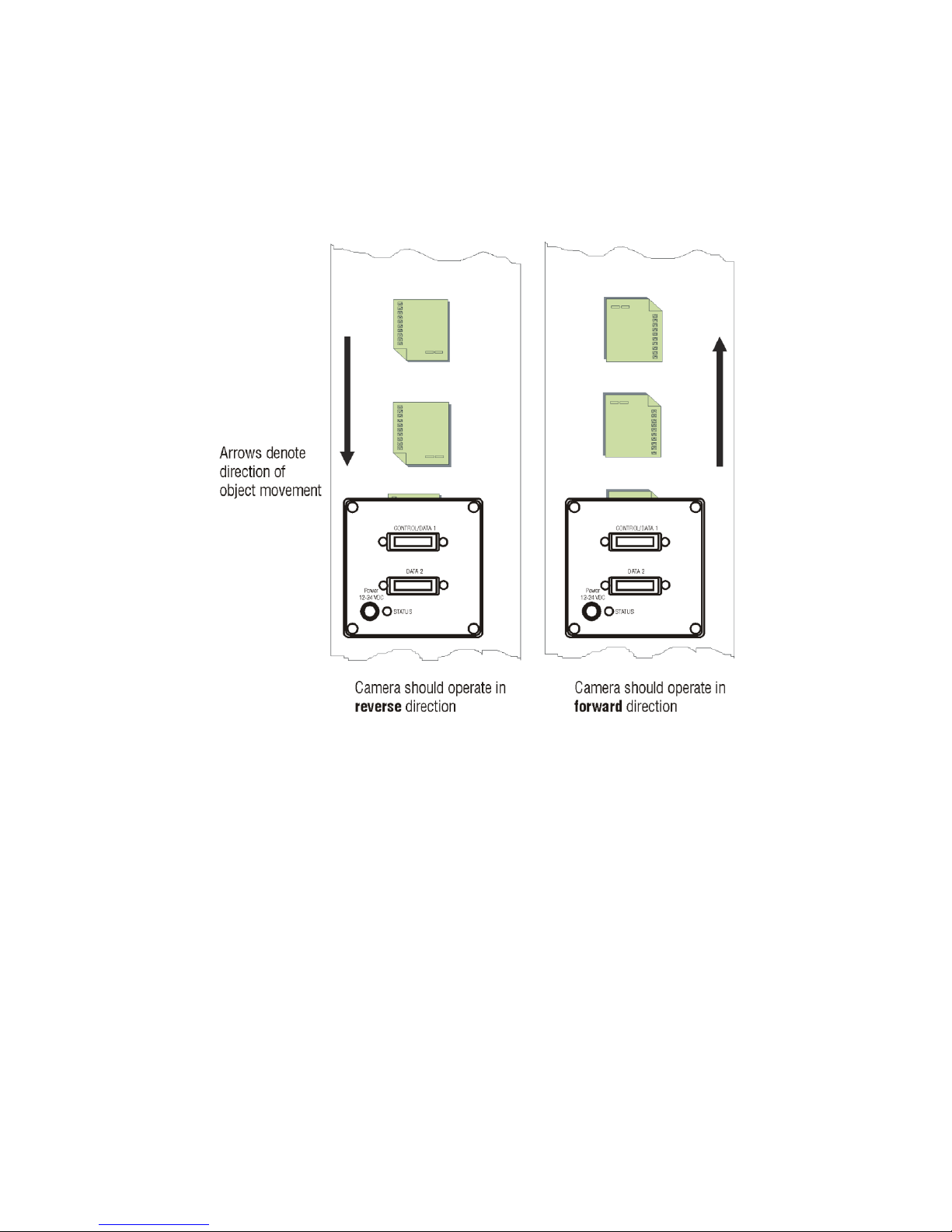
Camera Direction
Selectable camera direction accommodates an object direction change on a web and allows you to mount
th e cam era ―u p sid e down‖.
Note: The example here assumes the use of a lens (which inverts the image).
Figure 4: Object Movement and Camera Direction Example, with a Lens
Teledyne DALSA 03-032-20180-01

16 Piranha4 4K Camera Color User's Manual
Mechanicals
[ADD MECHANICAL FROM PDF 03-129-20071-01]
Figure 6: Camera Mechanical (shown with optional heat sink below)
[ADD HEATSINK MECHANICAL FROM PDF 03-129-20071-01]
03-032-20180-00 Teledyne DALSA
Piranha4 4K Color Camera User's Manual 17
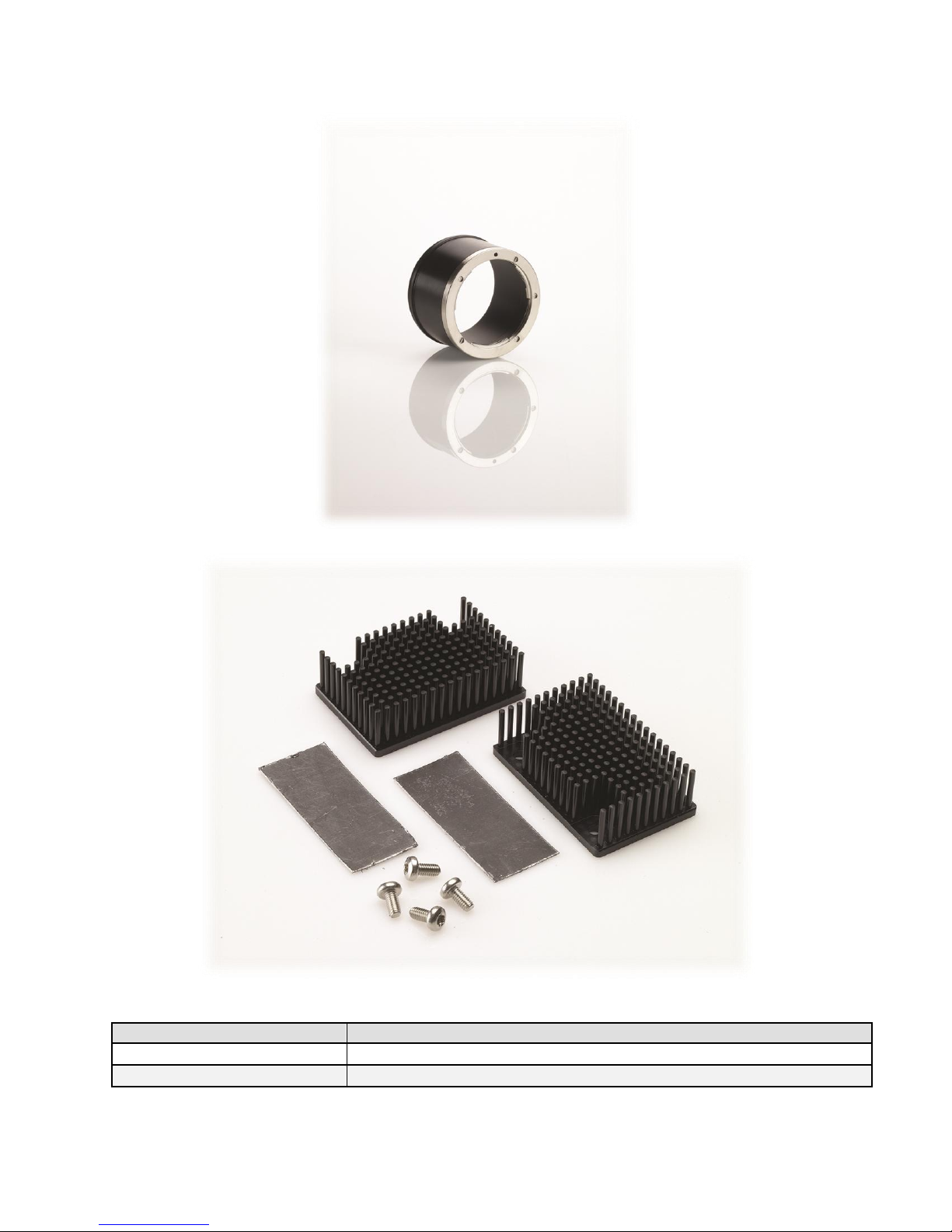
Part No.
Description
AC-LN-00002-A0-R
M58 to F-mount adapter (12mm BFD), heavy duty
AC-MS-00108-00-R
Heat sink for P4-4k/ 2k cameras
Figure 7: Piranha4 Heat Sink Accessories Kit
Optional Lens Mount and Heat Sink Accessories
Figure 6: Nikon M58 to F-Mount Adapter
Teledyne DALSA 03-032-20180-01

18 Piranha4 4K Camera Color User's Manual
Camera Mounting and Heat Sink Considerations
Up to tow optional heat sinks can be installed on the Piranha4 camera. As illustrated, they are ideally
positioned to allow close spacing of the cameras. These heat sinks are designed to provide adequate
convection cooling when not obstructed by enclosures or mounting assemblies.
Teledyne DALSA recognises that each cust omer ‘s app lication can be unique. In consideration, the P4
camera heat sinks have been designed in such a way that they can be repositioned on the different faces
of the camera or removed entirely, depending on the mounting configuration and its heat sinking
potential.
Repositioning or removal of the heat sinks must be performed with care in order to avoid temperature
issues. The camera has the ability to measure its internal temperature. Use this feature to record the
internal temperature of the camera when it is mounted in your system and operating under the worst
case conditions. The camera will stop outputting data if its internal temperature reaches 80 °C.
Filters
CMOS cameras are responsive to infrared (IR) wavelengths of light. Infrared light can be problematic
with halogen light sources but is not an issue with white LED sources. When infrared light is present
with this camera color fidelity is reduced. To prevent infrared from distorting the images you scan, use
an IR cut off filter such as a BG-38 on the lens.
03-032-20180-01 Teledyne DALSA

Piranha4 4K Color Camera User's Manual 19
2. Quick, Simple Steps to
Acquire an Image
For users who are familiar with Camera Link cameras, have a basic understanding of their imaging
requirements, and who are primarily interested in evaluating the Piranha4 camera, an overview of the
steps required to get this camera operational and acquiring images quickly can be found in Appendix C:
Quick Setup and Image Acquisition.
Teledyne DALSA 03-032-20180-01

20 Piranha4 4K Camera Color User's Manual
3. Software and Hardware Setup
Recommended System Requirements
To achieve best system performance, the following minimum requirements are recommended:
High bandwidth frame grabber, e.g. Xcelera-CL PX8 Full Camera Link frame grabber (Part # OR-
X8CO-XPF00): www.teledynedalsa.com/ imaging/ products/ fg/ OR-X8C0-XPF00/ .
Operating systems: Windows XP / Vista / 7, 32 / 64-bit.
Setup Steps: Overview
Take the following steps in order to setup and run your camera system. They are described briefly below
and in more detail in the sections that follow.
1. Install and Configure Frame Grabber and Software
We recommend the Xcelera-CL PX8 Full frame grabber or equivalent, described in detail on the
teledynedalsa.com site here. If your host computer does not have a PX8 full Camera Link frame grabber
then you will need to install one. Follow the m anu facturer ‘s installation in str u ct ions.
A GenCP (Generic Control Protocol) compliant XML device description file is embedded within the
camera firmware allowing GenCP-compliant applications to kn ow the ca m era‘s cap abilities im m ed iately
after connection. Installing SaperaLT gives you access to the CamExpert GUI, a tool that supports GenCPcompliant devices.
2. Connect Camera Link and Power Cables
Connect the Camera Link cables from the camera to the computer.
Connect a power cable from the camera to a +12 VDC to +24 VDC power supply.
3. Establish communicating with the camera
Start the GUI and establish communication with the camera.
ASCII Commands
As an alternative to the CamExpert (or equivalent) GUI, you can communicate with this camera using
ASCII-based commands. A complete list of the commands can be found here, Appendix B: ASCII
Commands.
4. Operate the Camera
At this point you will be ready to start operating the camera in order to acquire images, set camera
functions, and save settings.
03-032-20180-01 Teledyne DALSA

Piranha4 4K Color Camera User's Manual 21
Step 1. Install and configure the frame grabber
and software
Install Frame Grabber
Install a Full configuration Camera Lin k fram e grabber accor d ing to th e m anu facturer‘s description .
We recommend the Xcelera-CL PX8 frame grabber or equivalent, described in detail on the
teledynedalsa.com site here.
Install Sapera LT and CamExpert GUI
Communicate with the camera using a Camera Link-compliant interface. We recommend you use
CamExpert. CamExpert is the camera interfacing tool supported by the Sapera library and comes
bundled with SaperaLT. Using CamExpert is the simplest and quickest w ay to send commands to and
receive information from the camera.
Camera Link Environment
These cameras implement the Camera link specification, which defines the device capabilities.
The Camera link XML device description file is embed ded within the camera firmware allowing Camera
link-com p lia nt ap plication s to r ecognize the cam eras‘ capabilities im m ed iately after con n ection .
Teledyne DALSA 03-032-20180-01
22 Piranha4 4K Camera Color User's Manual
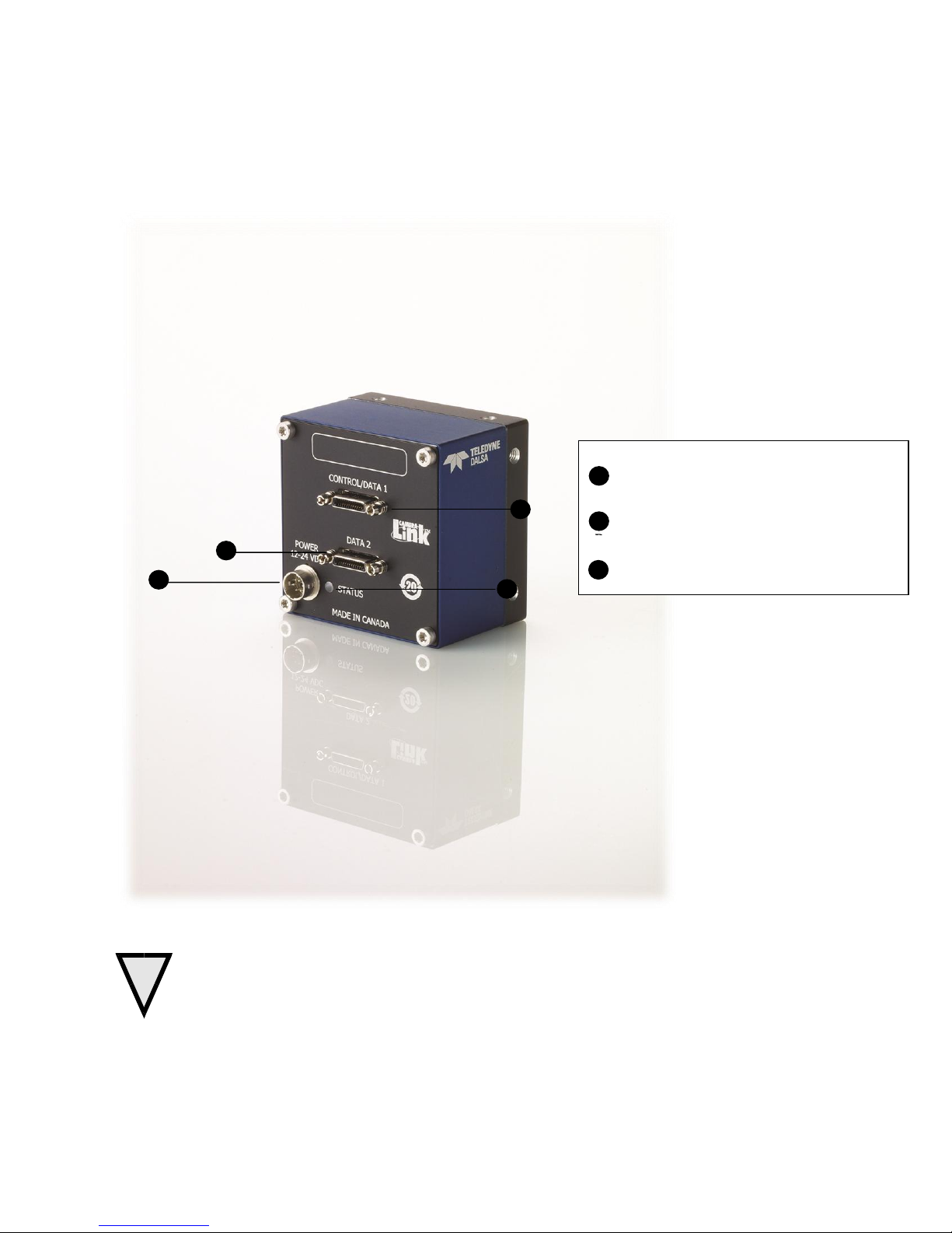
!
B
B
C
A
Power
+12V to +24V DC Hirose 6-pin
Control & Data
Camera Link 26-pin SDR26 connectors
Status
Diagnostic LED
A
B
C
Step 2. Connect Data, Trigger, and Power Cables
Note: the use of cables types and lengths other than those specified may result in increased emission or
decreased immunity and performance of the camera.
Figure 8: Input and Output, trigger, and Power Connectors
WARNING! Grounding Instructions
Static electricity can damage electronic components. It‘s critical that you d ischarge any static
electrical charge by touching a grounded surface, such as the metal computer chassis, before
handling the camera hardware.
03-032-20180-01 Teledyne DALSA
Piranha4 4K Color Camera User's Manual 23
Data 2
Control / Data 1
Camera
Connector
Right Angle
Frame Grabber
Connector
Channel Link
Signal
Camera
Connector
Right Angle
Frame Grabber
Connector
Channel Link
Signal
1 1 inner shield
1 1 inner shield
14
14
inner shield
14
14
inner shield
2
25
Y0- 2 25
X0-
15
12
Y0+
15
12
X0+ 3 24
Y1- 3 24
X1-
16
11
Y1+
16
11
X1+ 4 23
Y2- 4 23
X2-
17
10
Y2+
17
10
X2+ 5 22
Yclk-
5
22
Xclk-
18 9 Yclk+
18 9 Xclk+
6
21
Y3- 6 21
X3-
19 8 Y3+
19 8 X3+
7
20
100 ohm
7
20
SerTC+
20 7 terminated
20 7 SerTC-
8
19
Z0- 8 19
SerTFG-
21 6 Z0+
21 6 SerTFG+
9
18
Z1- 9 18
CC1-
22 5 Z1+
22 5 CC1+
10
17
Z2-
10
17
CC2+
23 4 Z2+
23 4 CC2-
11
16
Zclk-
11
16
CC3-
24 3 Zclk+
24 3 CC3+
12
15
Z3-
12
15
CC4+
25 2 Z3+
25 2 CC4-
13
13
inner shield
13
13
inner shield
26
26
inner shield
26
26
inner shield
Signal
Configuration
CC1
EXSYNC
CC2
Spare
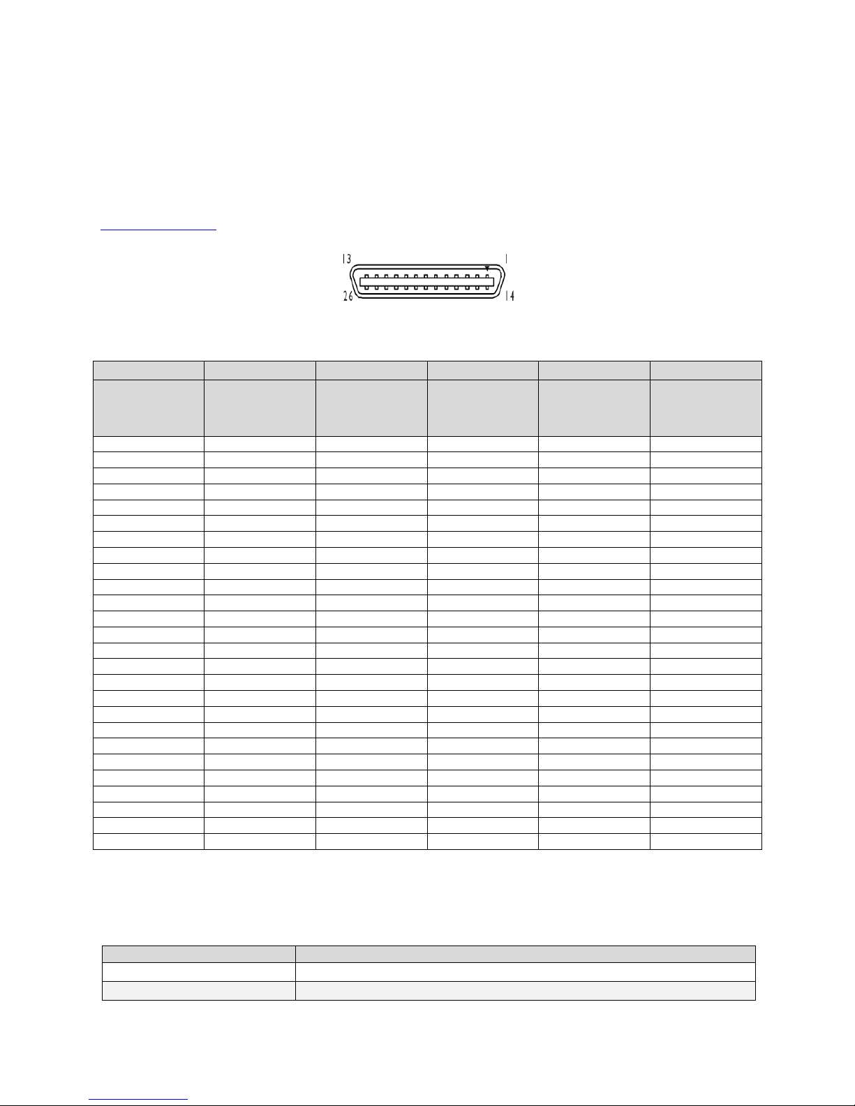
Data Connector: Camera Link
The camera uses two Camera Link SDR26 cables transmitting the Camera Link Base, Medium, Full, or
Deca configuration. The figure below shows the SDR26 Camera Link Connector and the tables that follow
list the Camera Link configurations.
For detailed information on Camera Link please refer to the Camera Link Road Map available from the
Knowledge Center on the Teledyne DALSA Web site.
Figure 9. SDR26 Camera Link Connector
Note:
*Exterior Overshield is connected to the shells of the connectors on both ends. Unused pairs should be terminated in 100 ohms at
both ends of the cable. Inner shield is connected to signal ground inside camera
Camera Link Bit Definitions
Teledyne DALSA 03-032-20180-01
24 Piranha4 4K Camera Color User's Manual
CC3
Direction
CC4
Spare
Red 1
D0..D7
Blue 1
D0..D7
Green 1
D0..D7
Red 2
D0..D7
Blue 2
D0..D7
Green 2
D0..D7
Red 3
D0..D7
Blue 3
D0..D7
Green 3
D0..D7
Red 4
D0..D7
Green 4
D0..D7
Red 4095
D0..D7
Blue 4095
D0..D7
Green 4095
D0..D7
Red 4096
D0..D7
Blue 4096
D0..D7
Green 4096
D0..D7
Blue 4
D0..D7
CL Port A
CL Port B
CL Port C
CL Clock
Line Valid
Table 4: Camera Control Configuration
For additional Camera Link documentation refer to the Teledyne DALSA Web site‘s Knowledge Center
application notes.
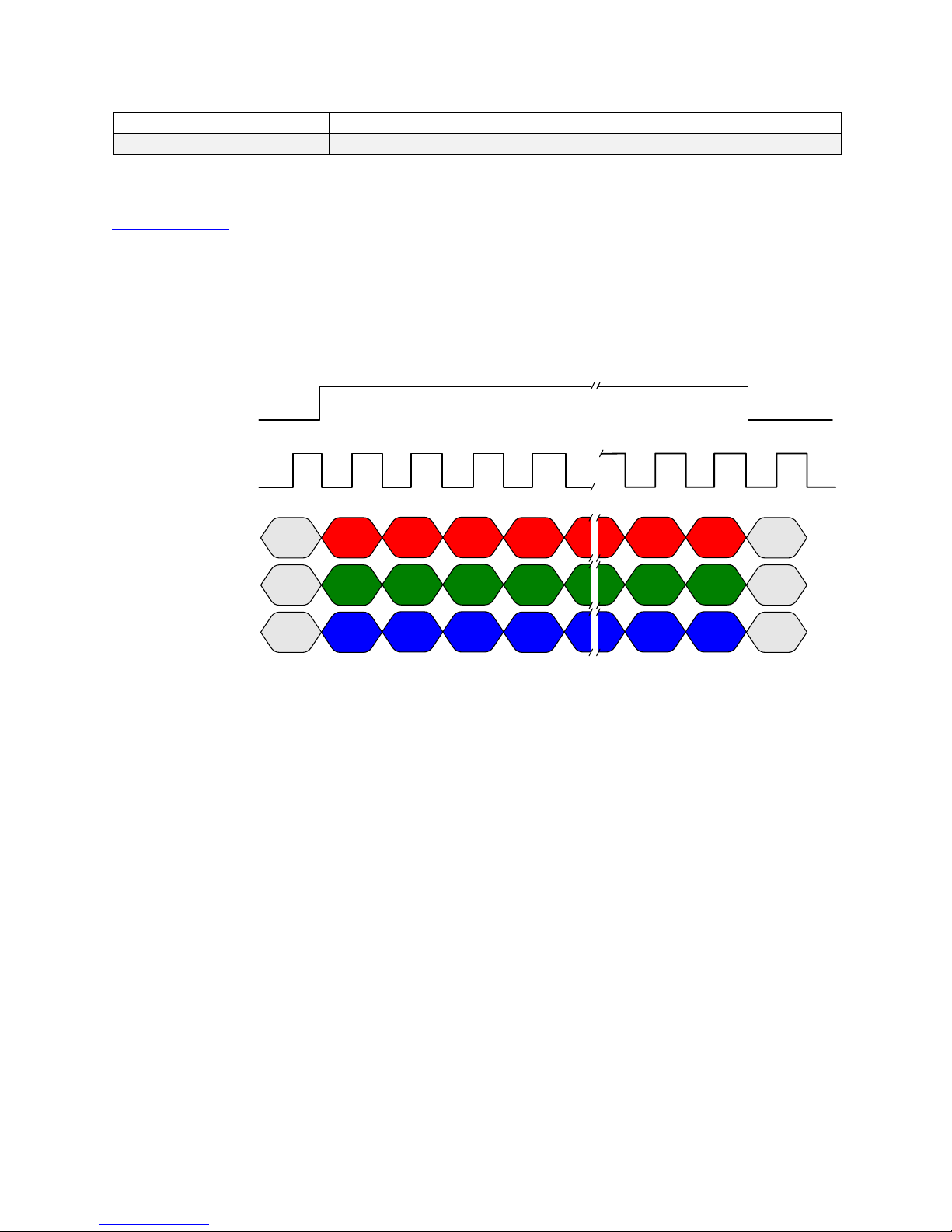
Camera Timing
Note: Inform ation on setting up the cam era‘s AOI can b e fou n d her e, Area of Interest (AOI) Setup.
RGB 8 bit CL Base, max line rate 20 kHz without AOI and 85 MHz CL Clock
This timing can be used for applications that require line rates only up to 20 kHz and therefore can use
Camera Link Base mode with only one cable.
The RGB output format is compatible with the Camera Link specification for Base RGB. Line rates up to
70 kHz can be achieved by using the Area of Interest (AOI) feature; where the smaller the AOI, the
greater the potential line rate.
03-032-20180-01 Teledyne DALSA
Piranha4 4K Color Camera User's Manual 25
Red 1
D0..D7
Blue 1
D0..D7
Green 1
D0..D7
Red 3
D0..D7
Blue 3
D0..D7
Green 3
D0..D7
Red 5
D0..D7
Blue 5
D0..D7
Green 5
D0..D7
Red 7
D0..D7
Green 7
D0..D7
Red 4093
D0..D7
Blue 4093
D0..D7
Green 4093
D0..D7
Red 4095
D0..D7
Blue 4095
D0..D7
Green 4095
D0..D7
Blue 7
D0..D7
CL Port A
CL Port B
CL Port C
CL Clock
Line Valid
Red 2
D0..D7
Blue 2
D0..D7
Green 2
D0..D7
Red 4
D0..D7
Blue 4
D0..D7
Green 4
D0..D7
Red 6
D0..D7
Blue 6
D0..D7
Green 6
D0..D7
Red 8
D0..D7
Green 8
D0..D7
Red 4094
D0..D7
Blue 4094
D0..D7
Green 4094
D0..D7
Red 4096
D0..D7
Blue 4096
D0..D7
Green 4096
D0..D7
Blue 8
D0..D7
CL Port D
CL Port E
CL Port F
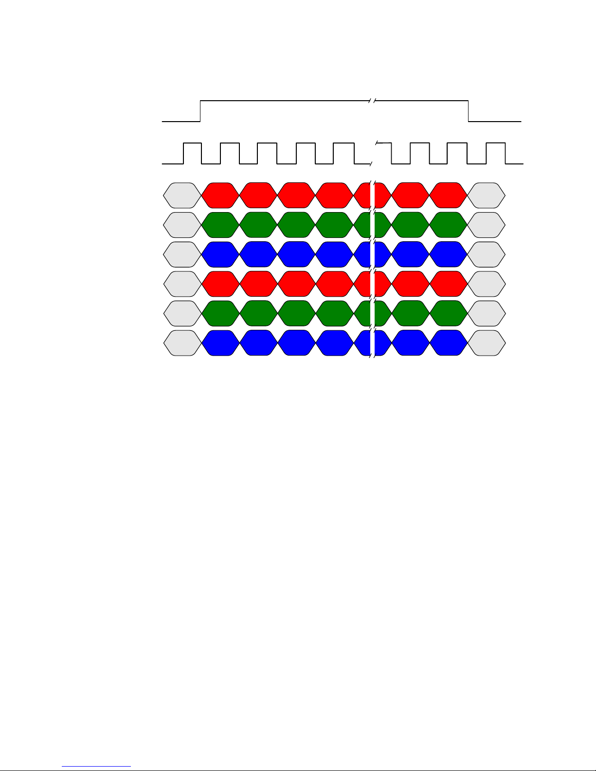
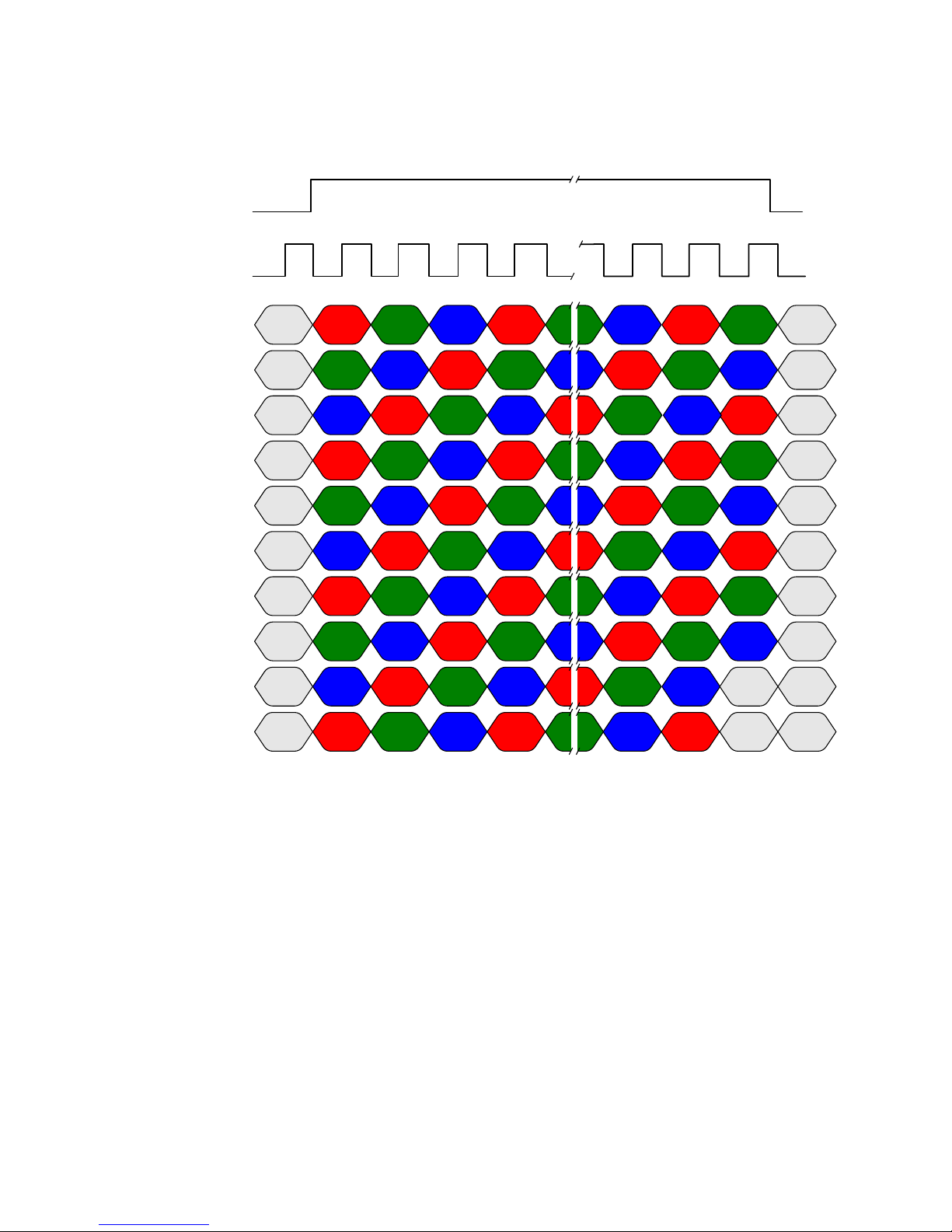
RGB 8 bit CL Medium, max line rate 40 kHz without AOI and 85 MHz CL clock
This timing can be used for applications that require line rates up to 40 kHz and therefore must use
Camera Link Medium mode and two cables.
The RGB output format is compatible with the Camera Link specification for Medium RGB. Line rates up
to 70 kHz can be achieved by using the Area of Interest (AOI) feature; where the smaller the AOI, the
greater the potential line rate.
Teledyne DALSA 03-032-20180-01
26 Piranha4 4K Camera Color User's Manual
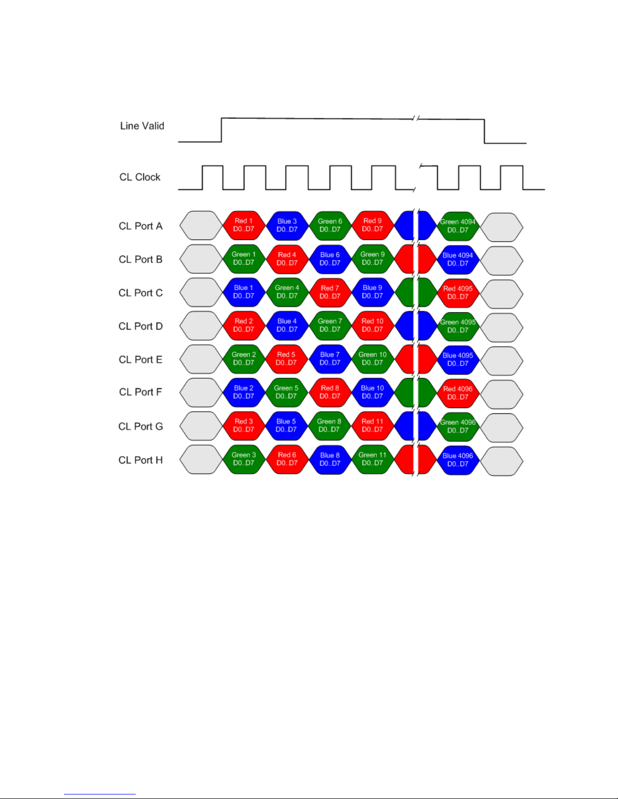
RGB 8 bit CL Full, max line rate 55 kHz without AOI and 85 MHz CL clock
Note: The inserted dummy pixels at the end.
This timing can be used for applications that require line rates up to 55 kHz and therefore must use
Camera Link Deca mode and two cables.
The RGB output format is not defined in the Camera Link specification Full. The RGB format is such that
when using a Camera Link frame grabber compatible with the Full format configured for the mono
standard, the R, G and then B pixels will be written sequentially into the frame grabber buffer. This
process simplifies the extraction of the RGB data from the frame grabber buffer by the host application.
Line rates up to 70 kHz can be achieved by using the Area of Interest (AOI) feature; where the smaller the
AOI, the greater the potential line rate.
03-032-20180-01 Teledyne DALSA
Piranha4 4K Color Camera User's Manual 27
Red 1
D0..D7
Blue 1
D0..D7
Green 1
D0..D7
Red 2
D0..D7
Blue 2
D0..D7
Green 2
D0..D7
Red 3
D0..D7
Blue 3
D0..D7
Green 3
D0..D7
Red 4
D0..D7
Blue 4
D0..D7
Green 4
D0..D7
Red 5
D0..D7
Blue 5
D0..D7
Green 5
D0..D7
Red 6
D0..D7
Blue 6
D0..D7
Green 6
D0..D7
Red 7
D0..D7
Blue 7
D0..D7
Green 7
D0..D7
Red 8
D0..D7
Blue 8
D0..D7
Green 8
D0..D7
Red 9
D0..D7
Blue 9
D0..D7
Green 9
D0..D7
Red 10
D0..D7
Blue 10
D0..D7
Green 10
D0..D7
Red 11
D0..D7
Green 11
D0..D7
Red 4095
D0..D7
Blue 4095
D0..D7
Green 4095
D0..D7
Red 4096
D0..D7
Blue 4096
D0..D7
Green 4096
D0..D7
Blue 4092
D0..D7
Green 4092
D0..D7
Red 4093
D0..D7
Blue 4093
D0..D7
Green 4093
D0..D7
Red 4094
D0..D7
Blue 11
D0..D7
Red 12
D0..D7
Green 12
D0..D7
Blue 12
D0..D7
Red 13
D0..D7
Green 13
D0..D7
Blue 13
D0..D7
Red 14
D0..D7
Red 4092
D0..D7
Blue 4091
D0..D7
CL Port A
CL Port B
CL Port C
CL Port D
CL Port E
CL Port F
CL Port G
CL Port H
CL Port I
CL Port K
CL Clock
Line Valid
Blue 4094
D0..D7
Green 4094
D0..D7
Green 4091
D0..D7
Red 4091
D0..D7
Blue 4089
D0..D7
Green 4089
D0..D7
Red 4090
D0..D7
Blue 4090
D0..D7
Green 4090
D0..D7
Red 4089
D0..D7
Blue 4088
D0..D7
Green 4088
D0..D7
Red 4088
D0..D7
Blue 4087
D0..D7
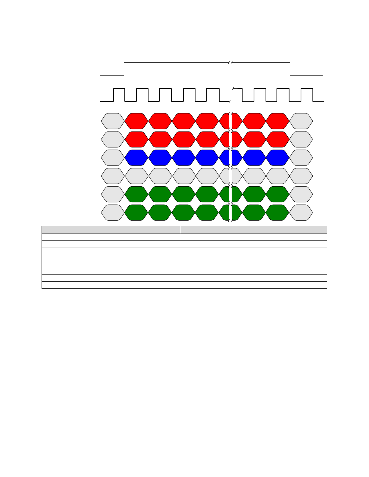
RGB 8 bit CL Deca, max line rate 69 kHz without AOI and 85 MHz CL clock
Note: The inserted dummy pixels at the end.
This timing can be used for applications that require line rates up to 69 kHz and therefore must use
Camera Link Deca mode and two cables.
The RGB output format is not defined in the Camera Link specification Deca. The RGB format is such that
when using a Camera Link frame grabber compatible with the Deca format configured for the mono
standard, the R, G and then B pixels will be written sequentially into the frame grabber buffer. This
process simplifies the extraction of the RGB data from the frame grabber buffer by the host application.
Line rates up to 70 kHz can be achieved by using the Area of Interest (AOI) feature; where the smaller the
AOI, the greater the potential line rate.
Teledyne DALSA 03-032-20180-01
28 Piranha4 4K Camera Color User's Manual
Red 1
D0..D7
Blue 1
D0..D7
Green 1
D0..D7
Red 1
D8..D9
Blue 1
D8..D9
Red 4
D0..D7
Red 4096
D0..D7
Blue 4096
D0..D7
Green 4096
D0..D7
Blue 4
D0..D7
Green 4
D0..D7
CL Port A
CL Port B
CL Port C
CL Port D
CL Port E
CL Port F
CL Clock
Line Valid
Green 2
D0..D7
Green 3
D0..D7
Green 4095
D0..D7
Green 1
D8..D9
Green 4096
D8..D9
Green 4
D8..D9
Green 2
D8..D9
Green 3
D8..D9
Green 4095
D8..D9
Red 2
D0..D7
Red 3
D0..D7
Red 4095
D0..D7
Blue 2
D0..D7
Blue 3
D0..D7
Blue 4095
D0..D7
Red 2
D8..D9
Blue 2
D8..D9
Red 3
D8..D9
Blue 3
D8..D9
Red 4
D8..D9
Blue 4
D8..D9
Red 4095
D8..D9
Blue 4095
D8..D9
Red 4096
D8..D9
Blue 4096
D8..D9
Port B Bit Assignments
Port F Bit Assignments
D0
Red 8
D0
Green 8
D1
Red 9
D1
Green 9
D2
N/ A
D2
N/ A
D3
N/ A
D3
N/ A
D4
Blue 8
D4
N/ A
D5
Blue 9
D5
N/ A
D6
N/ A
D6
N/ A
D7
N/ A
D7
N/ A
RGB 10 bit CL Medium, max line rate 20 kHz without AOI and 85 MHz CL clock
This timing can be used for applications that require line rates up to 20 kHz and therefore must use
Camera Link Medium mode and two cables.
The RGB output format is compatible with the Camera Link specification for Medium RGB. Line rates up
to 70 kHz can be achieved by using the Area of Interest (AOI) feature; where the smaller the AOI, the
greater the potential line rate.
03-032-20180-01 Teledyne DALSA

Piranha4 4K Color Camera User's Manual 29
Red 1
D0..D7
Blue 1
D0..D7
Green 1
D0..D7
Red 1
D8..D11
Blue 1
D8..D11
Red 4
D0..D7
Red 4096
D0..D7
Blue 4096
D0..D7
Green 4096
D0..D7
Blue 4
D0..D7
Green 4
D0..D7
CL Port A
CL Port B
CL Port C
CL Port D
CL Port E
CL Port F
CL Clock
Line Valid
Green 2
D0..D7
Green 3
D0..D7
Green 4095
D0..D7
Green 1
D8..D11
Green 4096
D8..D11
Green 4
D8..D11
Green 2
D8..D11
Green 3
D8..D11
Green 4095
D8..D11
Red 2
D0..D7
Red 3
D0..D7
Red 4095
D0..D7
Blue 2
D0..D7
Blue 3
D0..D7
Blue 4095
D0..D7
Red 2
D8..D11
Blue 2
D8..D11
Red 3
D8..D11
Blue 3
D8..D11
Red 4
D8..D11
Blue 4
D8..D11
Red 4095
D8..D11
Blue 4095
D8..D11
Red 4096
D8..D11
Blue 4096
D8..D11
Port B Bit Assignments
Port F Bit Assignments
D0
Red 8
D0
Green 8
D1
Red 9
D1
Green 9
D2
Red 10
D2
Green 10
D3
Red 11
D3
Green 11
D4
Blue 8
D4
N/ A
D5
Blue 9
D5
N/ A
D6
Blue 10
D6
N/ A
D7
Blue 11
D7
N/ A
RGB 12 bit CL Medium, max line rate 20 kHz without AOI and 85 MHz CL clock
This timing can be used for applications that require line rates up to 20 kHz and therefore must use
Camera Link Medium mode and two cables.
The RGB output format is compatible with the Camera Link specification for Medium RGB. Line rates up
to 70 kHz can be achieved by using the Area of Interest (AOI) feature; where the smaller the AOI, the
greater the potential line rate.
Teledyne DALSA 03-032-20180-01

30 Piranha4 4K Camera Color User's Manual
Distance Tested
Cable Manufacture
Frame grabber
10 m
Component Express
PX4 and PX8
15 m
Component Express
PX8
30 m
Hewtech
PX8
Custom AOI Rules
1) The sensor has pixels numbered 0 to 4096*.
2) Three values (red, blue, green) are output per pixel in RGB mode.
3) Whether mirroring is on or off, 0 is the leftmost pixel.
4) Whether mirroring is on or off, AOI 1 is readout first.
5) In normal mode, AOI 1 is closest to the sensor‘s left edge.
6) In mirror mode, AOI 1 is closest to the sensor‘s right edge.
*4080 active pixels, the last 16 pixels are inactive.
Base and Medium Modes
1) The total number of pixels within each AOI must be a multiple of 8 and must be greater than or
equal to 40.
2) In normal mode, the first pixel of each AOI (AOI left edge) must have the location 8i, where i = 0,
1, 2 .., 511 (i.e. 8, 960 are allowed, 12 is not allowed).
3) In mirror mode, the first pixel of each AOI (AOI right edge) must have the location 8i + 7, where i
= 0,1,2 .., 511 (i.e. 7, 15, 4095 are allowed, 8 is not allowed).
Deca RGB Mode
1) The total number of pixels within each AOI must be a multiple of 40.
2) In normal mode, the first pixel of each AOI (AOI left edge) must have the location 8i, where i = 0,
1, 2 .., 511 (i.e. 8, 960 are allowed, 12 is not allowed).
3) In mirror mode, the first pixel of each AOI (AOI right edge) must have the location 8i + 7, where i
= 0,1,2 .., 511 (i.e. 7, 15, 4095 are allowed, 8 is not allowed).
Camera Link cable quality and length
The maximum allowable Camera Link cable length depends on the quality of the cable used and the
Camera Link strobe frequency. Cable quality degrades over time as the cable is flexed. In addition, as the
Camera Link strobe frequency is increased the maximum allowable cable length will decrease. We do not
guarantee good imaging performance with low quality cables of any length. In general, we recommend
the use of high quality cables for any cable length.
The following table lists some results achieved using the P4 camera and a selection of cables and frame
grabbers.
Input Signals, Camera Link
The camera accepts control inputs through the Camera Link SDR26F connector. The camera ships in
internal sync, and internally programmed integration.
03-032-20180-01 Teledyne DALSA

Piranha4 4K Color Camera User's Manual 31
Clocking Signal
Indicates
LVAL (high)
Outputting valid line
DVAL
Not used
STROBE (rising edge)
Valid data
FVAL
Set to 0
Pin
Description
Pin
Description
1
+12 V to +24 V DC
4
GND
2
+12 V to +24 V DC
5
GND
3
+12 V to +24 V DC
6
GND
!
EXSYNC (Exposure Start)
Line rate can be set internally using the GenICam features. The external control signal EXSYNC is
optional and enabled through the user interface. This camera uses the falling edge of EXSYNC to start the
exposure period.
The EXSYNC signal tells the camera when to integrate the image, followed by the readout. It can be either
an internally generated signal by the camera, or it can be supplied externally via the serial interface.
Depending upon the mode of operation the high time of the EXSYNC signal can represent the integration
period.
Note: The EXSYN C sign a l is m easured at CC1 and w ill giv e a ―tru e‖ m easu remen t (i.e. within th e
measurement resolution of 25 ns) even though the camera will only trigger at a maximum of 70 KHz.
Output Signals, Camera Link Clocking Signals
These signals indicate when data is valid, allowing you to clock the data from the camera to your
acquisition system. These signals are part of the Camera Link configuration and you should refer to the
Camera Link Implementation Road Map, available at our Knowledge Center, for the standard location of
these signals.
Power Connector
WARNING: It is extremely important that you apply the appropriate voltages to your camera.
Incorrect voltages may damage the camera. Input voltage requirement: +12 VDC to +24 VDC,
2 Amps. Before connecting power to the camera, test all power supplies.
Figure 10: 6-pin Hirose Circular Male Power Plug—Power Connector
Table 5. Power Plug Pinout
The camera requires a single voltage input +12 VDC to +24 VDC. The camera meets all performance
specifications using standard switching power supplies, although well-regulated linear supplies provide
optimum performance.
Teledyne DALSA 03-032-20180-01

32 Piranha4 4K Camera Color User's Manual
!
Color of Status LED
Meaning
Off
No power or hardware malfunction
Blinking Green
Powering up or calibrating
Green
Ready
Red
Error. Check BiST register for the specific error
WARNING: When setting up the camera’s power supplies follow these guidelines:
Apply the appropriate voltages.
Protect the camera with a 2 amp slow-blow fuse between the power supply and the camera.
Do not use the shield on a multi-conductor cable for ground.
Keep leads as short as possible in order to reduce voltage drop.
Use high-quality supplies in order to minimize noise.
Note: If your power supply does not meet these requirements, then the camera performance specifications
are not guaranteed.
LEDs
The camera is equipped with an LED on the back to display the operational status of the camera. The
table below summarizes the operating states of the camera and the corresponding LED states. When more
than one condition is active, the LED indicates the condition with the highest priority.
Step 3. Establish Communication with the
Camera
Power on the camera
Turn on the camera‘s power supply. You may have to wait while the camera readies itself for operation.
The camera must boot fully before it will be recognized by the GUI—the LED shines green once the
camera is ready.
Connect to the frame grabber
1. Start Sapera CamExpert (or equivalent Camera Link compliant interface) by double clicking the
desktop icon created during the software installation.
2. CamExpert will search for installed Sapera devices. In the Devices list area on the left side, the
connected frame grabber will be shown.
3. Select the frame grabber device by clicking on the name.
Note: The first time you set up the camera you will need to establish a communication link between the
camera and frame grabber. Instructions are available here in Appendix F: Camera, Frame Grabber
Communication.
Connect to the camera
1. Start a new Sapera CamExpert application (or equivalent Camera Link compliant interface) by
double clicking the desktop icon created during the software installation.
2. In the Devices list area on the left side, select the COM port below the Camera Link label.
03-032-20180-01 Teledyne DALSA

Piranha4 4K Color Camera User's Manual 33
Check LED Status
If the camera is operating correctly at this point, the diagnostic LED will shine green.
Software Interface
All the camera features can be controlled through the CamExpert interface. For example, under the
Sensor Control menu in the camera window you can control the line rate and exposure times.
Teledyne DALSA 03-032-20180-01

34 Piranha4 4K Camera Color User's Manual
A note on the CamExpert examples shown here: The examples shown for illustrative purposes and may
not entirely reflect the features and parameters available from the camera model used in your
application.
At this point your host and camera system should b e setu p an d you can verify the ca m era‘s oper ation by
retr ieving a test p attern and settin g the camera‘s tr ig ger and exp osu r e tim e.
Using Sapera CamExpert with Piranha4
Cameras
CamExpert is the camera interfacing tool supported by the Sapera library. When used with a Piranha4
camera, CamExpert allows a user to test all camera operating modes. Additionally CamExpert saves the
camera user settings configuration to the camera or saves multiple configurations as individual camera
parameter files on the host system (*.ccf). CamExp ert can also be u sed to u p gr ad e th e camera‘s softw are.
An important component of CamExpert is its live acquisition display window which allows immediate
verification of timing or control parameters without the need to run a separate acquisition program.
For context sensitive help, click on the button then click on a camera configuration parameter. A
short description of the configuration parameter will be shown in a popup. Click on the button to
open the help file for more descriptive information on CamExpert.
The central section of CamExpert provides access to the camera features and parameters.
Note: The availability of the features is dependent on the CamExpert user setting.
03-032-20180-01 Teledyne DALSA

Piranha4 4K Color Camera User's Manual 35
CamExpert Panes
Figure 11. CamExpert’s Camera Control Window
Teledyne DALSA 03-032-20180-01

36 Piranha4 4K Camera Color User's Manual
Acquisition control button:
Click once to start live grab, click again to stop.
Single frame grab:
Click to acquire one frame from device.
Figure 12. CamExpert GUI showing connected camera
The CamExpert application uses panes to simplify choosing and configuring camera files or acquisition
parameters for the installed device.
Device Selector pane: View and select from any installed Sapera acquisition device. Once a device is
selected CamExpert will only present acquisition parameters applicable to that device. Optionally
select a camera file included with the Sapera installation or saved by the user.
Parameters pane: Allows viewing or changing all acquisition parameters supported by the
acquisition device. CamExpert displays parameters only if those parameters are supported by the
installed device. This avoids confusion by eliminating parameter choices when they do not apply to
the hardware in use.
Display pane: Provides a live or single frame acquisition display. Frame buffer parameters are shown
in an information bar above the image window.
Control Buttons: The Display pane includes CamExpert control buttons. These are:
03-032-20180-01 Teledyne DALSA

Piranha4 4K Color Camera User's Manual 37
Software trigger button:
With the I/ O control parameters set to Trigger Enabled / Software
Trigger type, click to send a single software trigger command.
CamExpert display controls:
(these do not modify the frame buffer data)
Stretch image to fit, set image display to original size, or zoom the
image to virtually any size and ratio.
Histogram / Profile tool:
Select to view a histogram or line/ column profile during live
acquisition or in a still image.
Output Message pane: Displays messages from CamExpert or the device driver.
Review a Test Image
The camera is now ready to retrieve a test pattern. Select Image Format Control > Test Pattern and
choose one of the following available test images.
0. Off: Sensor Video
1. Grey Ramp
2. Ramp
Pixels: {1, 2, 3…}
Red Value: {0, 1, 2…}
Green Value: {102, 103, 104…}
Blue Value: {204, 205, 206…}
Values roll over at 255.
At this point you are ready to start operating the camera in order to acquire images, set camera functions,
and save settings.
Teledyne DALSA 03-032-20180-01

38 Piranha4 4K Camera Color User's Manual
4. Camera Operation
Factory Settings
The camera ships and powers up for the first time with the following factory settings:
Camera Link Medium, 8 bit pixels, 85 MHz
Internal trigger, line rate 10 kHz
Internal exposure control, exposure time 30.5 µs
Flat field disabled
User coefficients set to 1x
Offset 0, System Gain 1x
White balanced gains all set to 1x
Color correction, not applied
Corrected using an 80 mm lens and a magnification of 0.8
Check Camera and Sensor Information
Camera and sensor information can be retrieved via a controlling application—for example, the
CamExpert GUI shown in the following examples. Parameters such as camera model, firm ware version,
sensor characteristics, etc. are read to uniquely identify the connected device.
The camera information parameters are grouped together as members of the Camera Information set.
03-032-20180-01 Teledyne DALSA

Piranha4 4K Color Camera User's Manual 39
Figure 13. CamExpert’s Camera Information Window
Verify Temperature and Voltage
To determine the voltage and temperature at the camera, use the Refresh Voltage and Refresh
Temperature features found in the Camera Information set.
The temperature returned is the internal temperature in degrees Celsius. For proper operation, this value
should not exceed 80 °C. If the camera exceeds the designated temperature it will stop imaging and the
LED will turn red. Once you have diagnosed and remedied the issue use the reset camera function.
The voltage d isp layed is t h e cam er a‘s inpu t volt age.
Note: The voltage measurement feature of the camera provides results typically within 1%. This
measurement can be used to set the applied voltage to the camera.
Teledyne DALSA 03-032-20180-01

40 Piranha4 4K Camera Color User's Manual
Camera Information
Parameter
Choices
User Set Default Selector
Select the camera parameters to load when the camera is reset or powered up as the
Factory set, or as User Set 1 to 8.
Selecting the set from the list automatically saves it as the default set.
User Set Selector
Select the Factory or User set to Save or Load.
-Factory Set
-User Set 1 to 8.
User Set Load
Load the set specified by User Set Selector to the camera and make it the active /
current set.
User Set Save
Save the current set as selected user set.
Saving and Restoring Camera Settings
The parameters used to select, load and save user sets are grouped together under the Camera
Information set of features. There are 8 user sets available and one factory set.
Description of the Camera Settings
The camera operates in one of three settings:
1. Current session.
2. User setting.
3. Factory setting (read-only).
4. Default setting.
The current settings can be saved (thereby becoming the user setting) using the User Set Save parameter.
A previously saved user setting (User Set 1 to 8) or the factory settings can be restored using the User Set
Selector and User Set Load parameters.
Either the Factory or one of the User settings can be saved as the Default Setting by selecting the set in the
User Set Default Selector. The chosen set automatically saves as the default setting and is the set loaded
when the camera is reset or powered up.
The relationship between these three settings is illustrated in Figure 14. Relationship between the Camera
Settings:
03-032-20180-01 Teledyne DALSA

Piranha4 4K Color Camera User's Manual 41
Figure 14. Relationship between the Camera Settings
Active Settings for Current Session
The active setting for the current session is the set of configurations that are operating while the camera is
currently running, including all unsaved changes you have made to the settings before saving them.
These active settings are stored in the camera‘s volatile memory and will be lost and cannot be restored if
the camera resets or if the camera is powered down or loses power.
To save these settings for reuse the next time you power up or reset the camera, or to protect against
losing them in the case of power loss, you must save the current settings using the User Set Save
parameter. Once saved, the current settings become the selected User Set.
User Setting
The user setting is the saved set of camera configurations that you can customize, resave, and restore. By
default the user settings are shipped with the same settings as the factory set.
The command User Set Save saves the current settings to non-volatile memory as a User Set. The camera
automatically restores the last saved user settings when it powers up.
To restore the last saved user settings, select the User Set parameter you want to restore and then select
the User Set Load parameter.
Teledyne DALSA 03-032-20180-01

42 Piranha4 4K Camera Color User's Manual
Name
Taps
SPF*
Cables
Base
3
8, 10, 12
1
Medium
6
8, 10, 12
2
Full 8 8 2 Deca
10 8 2
Factory Settings
The factory setting is the camera settings that were shipped with the camera and which loaded during the
camera‘s first pow er -up. To load or restore the original factory settings, at any time, select the Factory
Setting parameter and then select the User Set Load parameter.
Note: By default, the user settings are set to the factory settings.
Default Setting
Either the Factory or one of the User settings can be used as the Default Setting by selecting the set in the
User Set Default Selector. The chosen set automatically becomes the default setting and is the set loaded
when the camera is reset of powered up.
Camera Link Configuration
*Set Pixel Format (number of bits per pixel)
Trigger Modes
The camera‘s image exposures are initiated by a trigger event. The trigger event is either a programmable
internal signal used in free running mode, an external input used for synchronizing exposures to external
triggers, or a programmed function call message by the controlling computer. These triggering modes are
described below.
Internal trigger (trigger disabled): The camera free-running mode has a programmable internal
timer for line rate and a programmable exposure period.
External trigger (trigger enabled): Exposures are controlled by an external trigger signal. The
external trigger signal is the Camera Link control line CC1.
Exposure Controls
Exposure Control modes define the method and timing of how to control the sensor integration period.
The integration period is the amount of time the sensor is exposed to incoming light before the video
frame data is transmitted to the controlling computer.
Exposure control is defined as the start of exposure and exposure duration.
The start of exposure can be an internal timer signal (free-running mode) or an external trigger
signal.
The exposure duration can be programmable (such as the case of an internal timer) or controlled by the
external trigger pulse width.
The camera can grab images in one of three ways. You determine the three imaging modes using a
combination of the Exposure Mode parameters (including I/ O param eters), Exposure Time and Line Rate
parameters.
03-032-20180-01 Teledyne DALSA

Piranha4 4K Color Camera User's Manual 43
Description
Line Rate
Exposure Time
Trigger Source
(Sync)
Internal line rate and exposure time
Internal, programmable
Internal programmable
Internal
External line rate and exposure time
Controlled by EXSYNC
pulse
External (EXSYNC)
External
EXSYNC pulse controlling the line
rate. Programmed exposure time
Controlled by EXSYNC
pulse
Internal programmable
External
Camera Controls
Parameter
Description
Line Rate (in Hz)
Camera line rate in Hz. Only available when the start line trigger parameter is
disabled (Trigger Mode off).
Exposure Mode
Set the op eration mod e for th e camer a‘s exp osure.
Trigger Width or Timed. Trigger Width is only available when Trigger Mode is
enabled.
Trigger Width
Uses the width of the current line trigger signal pulse to control the exposure
duration.
Timed
The exposure duration time is set using the Exposure Time feature and the
exposure starts with the Line Start event.
Exposure Time Selector
Internally generated. Allows for an independent exposu re time to be applied to
each individual color.
Exposure Time
Sets the exposure time (in microseconds). Exposure Mode feature must be set
to Timed
Figure 15. Exposure controls
The param eters used to select the imaging modes—trigger sources (sync), exposure time, and line rate—
are grouped together as the Camera Controls.
Teledyne DALSA 03-032-20180-01

44 Piranha4 4K Camera Color User's Manual
Exposure Modes in Detail
1. Internally Programmable Line rate and Internally Programmable Exposure Time (Default)
Line rate is the dominant factor when adjusting the line rate or exposure time. When setting the line rate,
exposure time will decrease, if necessary, to accommodate the new line rate. When adjusting the
exposure time the range is limited by the line rate.
Note: The camera will not set line periods shorter than the readout period.
GenICam parameters to set:
I / O Controls > Trigger Mode > Off
2. External Line Rate and External Exposure Time (Trigger Width)
In this mode, EXSYNC sets both the line period and the exposure time. The rising edge of EXSYNC marks
the beginning of the exposure and the falling edge initiates readout. Note:
GenICam parameters to set:
I / O Controls > Trigger Mode > On
Sensor Control > Exposure Mode > Trigger Width
Warning! When running external line rate and external exposure time, the line rate must not exceed 1 /
(exposure time + 1,500 ns). Under these conditions the exposure time will become indeterminate and
result in image artefacts. This is not the case when running internal exposure control.
3. External Line Rate, Programmable Exposure Time
In this mode, the line rate is set externally with the falling edge of EXSYNC generating the rising edge of
a programmable exposure time.
GenICam parameters to set:
I / O Controls > Trigger Mode > On
Sensor Control > Exposure Mode > Timed
03-032-20180-01 Teledyne DALSA

Piranha4 4K Color Camera User's Manual 45
1. External Trigger Off, Internal Exposure Control
Free running, not synchronized to an external signal
Programmable Line Time
Programmable Exposure
1
Sensor
Readout
2
27.5us
Sensor
Readout
2
>1.5us
Programmable Exposure
1
Programmable Exposure
1
Sensor
Readout
2
LVAL
2. External Trigger On, Internal Exposure Control
CC1 Falling edge triggers start of internal exposure
3
Line Time
Programmable Exposure
1
Sensor
Readout
2
27.5us
Sensor
Readout
2
>1.5us
Programmable Exposure
1
Programmable Exposure
1
Sensor
Readout
2
LVAL
CC1
3. External Trigger On, External Exposure Control
CC1 Falling edge triggers start of exposure
CC1 high duration sets the exposure time
Line Time
Exposure = X
1
Sensor
Readout
2
27.5us
Sensor
Readout
2
>1.5us
Sensor
Readout
2
LVAL
CC1
Exposure = X
2
X
1
X
2
Exposure = X
3
X
3
Notes:
1. Exposure time > 7 micro-seconds
2. Sensor Readout time = 14 micro-seconds
3. One additional falling edge during exposure is latched
Figure 16. Exposure Modes
Teledyne DALSA 03-032-20180-01

46 Piranha4 4K Camera Color User's Manual
Camera Control
Parameter
Description
Line Rate (in Hz)
Camera line rate in a range from 0 Hz to 70 KHz.
This feature is only available when the camera is in Internal Mode—
line trigger is disabled (Trigger Mode off).
Line Rates
Camera Link Configuration
Maximum Line Rate
Base
20 kHz, Base RGB8
Medium
41 kHz
Full
55 kHz
Deca
69 kHz (Deca RGB8)
Set Line Rate
To set th e cam er a‘s line r ate u se the line rate parameter, part of the Sensor Controls set. This feature can
only be used when the camera is in Internal mode—that is, when the start line trigger is disabled (Trigger
Mode Off).
Note: Line rate > (Exposure time + 1,500 ns) will return an error (― In valid Param eter‖) if th is condition is
not met. You must adjust these two parameters in the correct sequence to maintain this condition.
If the external line rate exceeds 70 kHz the camera will continue to output data at its maximum line rate
of 70 kHz. Though no image artefacts associated with over-speed will occur, you may notice that under
over-speed conditions the image will appear compressed and the appar ent distance travelled will be
reduced.
Note: 70 kHz line rate can be achieved using AOI mode for all Camera Link Mode. For more information, see Area of Interest (AOI)
Setup.
03-032-20180-01 Teledyne DALSA

Piranha4 4K Color Camera User's Manual 47
CL Clock
Rate
Number
of AOI
CL
Configuration
Line Rate Formula (Hz)
85 MH z
1
Base RGB8
Max: 70KHz
Medium RGB8
Max: 70KHz
Full RGB8
Max: 70KHz
Deca RGB8
Max: 70KHz
85 MH z
2
Base RGB8
Max: 70KHz
Medium RGB8
Max: 70KHz
Full RGB8
Max: 70KHz
Deca RGB8
Max: 70KHz
85 MH z
3
Base RGB8
Max: 70KHz
Medium RGB8
Max: 70KHz
Table 6: Line Rates vs AOI
Teledyne DALSA 03-032-20180-01

48 Piranha4 4K Camera Color User's Manual
Full RGB8
Max: 70KHz
Deca RGB8
Max: 70KHz
85 MH z
4
Base RGB8
Max: 70KHz
Medium RGB8
Max: 70KHz
Full RGB8
Max: 70KHz
Deca RGB8
Max: 70KHz
CL
Clock
Rate
Number
of AOI
CL
Configuration
Line Rate Formula (Hz)
66 MH z
1
Base RGB8
Max: 70KHz
Medium RGB8
Max: 70KHz
Full RGB8
Max:70KHz
Deca RGB8
Max: 70KHz
03-032-20180-01 Teledyne DALSA

Piranha4 4K Color Camera User's Manual 49
66 MH z
2
Base RGB8
Max: 70KHz
Medium RGB8
Max: 70KHz
Full RGB8
Max: 70KHz
Deca RGB8
Max: 70KHz
66 MH z
3
Base RGB8
Max: 70KHz
Medium RGB8
Max: 70KHz
Full RGB8
Max: 70KHz
Deca RGB8
Max: 70KHz
66 MH z
4
Base RGB8
Max: 70KHz
Medium RGB8
Max: 70KHz
Full RGB8
Max: 70KHz
Teledyne DALSA 03-032-20180-01

50 Piranha4 4K Camera Color User's Manual
Deca RGB8
Max: 70KHz
Sensor Controls
Black Level
Apply a digital addition after an FPN correction: ± 1/ 8 of the available range of
-32 to +31 in 8-bit mode, -128 to +127 in 10-bit mode, and -512 to +511 in 12-bit
mode.
Gain
Set the gain as an amplification factor applied to the video signal across all
pixels: 1x to 10x.
Image Format Control
Control the size of the transmitted image
Width
Width of the image.
Height
Height of the image in lines.
Pixel Format
8 bit depth to Camera Link.
Test Image Selector
Select an internal test image:
Off
Color Ramp
Grey Ramp
Set Exposure Time
To set th e cam er a‘s exp osure tim e, use the Exposure Time parameter—a member of the Sensor Controls
set. This feature is only available when the Exposure Mode parameter is set to Timed. The allowable
exposure range is from 7 µs to 3,000 µs, dependent on the value of the internal line rate.
GenICam parameters:
Sensor Controls > Exposure Time (Timed Exposure Mode) > 8 µs to 3,000 µs.
Control Gain and Black Level
The cameras provide gain and black level adjustments in the digital domain for the CM OS sensor. The
gain and black level controls can make small compensations to the acqu isition in situation s where
lighting varies and the lens iris cannot be easily adjusted. The user can evaluate gain and black level by
using CamExpert.
The parameters that control gain and black level are grouped together in the Sensor Controls set.
Set Image Size
To set the height of the image, and therefore the number of lines to scan, use the parameters grouped
under the Image Format Control set.
03-032-20180-01 Teledyne DALSA

Piranha4 4K Color Camera User's Manual 51
Serial Port Control
Action
Parameter
Options
Control the baud rate used by the
cam era‘s ser ial p ort
Baud Rate
9600 (factory default)
19200
57600
115200
230400*
460800*
921600*
Note: During connection CamExpert
automatically sets the camera to
maximum allowable baud.
*Your system requires a Px8 frame
grabber to achieve these baud rates.
Number of bits per character used in the
serial port
Data Size
8
Parity of the serial port
Parity
None
Number of stop bits per character used
in the serial port
Number of Stop
Bits
1
Image Format Control
Parameter
Description
Pixel Format
RGB8, RGB10, RGB12
Set Baud Rate
The baud rate sets the speed (in bits per second —bps) of the serial communication port and is available as
part of the Serial Port Control parameters.
Pixel Format
Use the Pixel Format feature, found in the Image Format Control set, to select the format of the pixel to
use during image acquisition.
Teledyne DALSA 03-032-20180-01

52 Piranha4 4K Camera Color User's Manual
Direction Control
Parameter
Description
Sensor Scan Direction
This command lets you select the Internal or external
direction control. Use this feature to accommod ate object
direction change on a web and to mount the camera
"upside down."
Scan Direction
Read the current direction.
Image Format Control
Parameter
Description
ReverseX
Off: All pixels are read out from left to right.
On: All pixels are read out from right to left.
Camera Information
Parameter
Description
Camera Reset
Resets the camera and puts in the default settings, including a 9600 baud
rate.
Camera Direction Control
Found in the I / O Control > Direction Control set of features.
Pixel Readout Direction (Mirroring Mode)
Set the tap readout from left to right or from right to left. This feature is especially useful if you want to
mou nt t h e cam era ―u pside down.‖
Resetting the Camera
The feature Camera Reset, part of the Transport Layer set, resets the camera. The camera resets with the
default settings, including a baud rate of 9600.
03-032-20180-01 Teledyne DALSA

Piranha4 4K Color Camera User's Manual 53
Video
Gain
Output
Video
Digital Processing (color)
-
+
Offset
BlackLevel
(ssb)
x
Gain
(ssg 3)
-
Calibrate FPN
flatfieldCalibrationFPN
(ccf)
xR
xG xB
White
Balancing
BalanceWhiteAuto
(bwa,
ssg(0,1,2))
X X X X
X X X X
X X X X
Color
Correction
colorCorrectionMode
(ctv)
x
Calibrate
PRNU
flatfieldCorrectionMode
flatfieldCalibrationPRNU
flatfieldCorrectionAlgorithm
(cpa,ffm)
Calibrating the Camera
Important Note: to ensure best results, the conditions und er which you calibrate the camera (e.g.
temperature and illumination) should be as close to the actual operating conditions as possible.
Overview
The following diagram and accompanying description explain the cameras signal processing chain. Each
element shown, with the exception of color interpolation, is u ser programmable.
Digital Processing
1. Fixed pattern noise (FPN) calibration is used to subtract any residual dark level that may occur in
the application.
2. Photo response non uniformity (PRNU) calibration is used to correct for variations in the
illumination intensity and / or lens vignetting. When performed, this calibration will cause the
Teledyne DALSA 03-032-20180-01
Figure 17: Flat Field Calibration in CamExpert
Figure 18: Camera Calibration Process.

54 Piranha4 4K Camera Color User's Manual
camera to have a flat response to a w hite target in the field of view. The output target value for
PRNU calibration can be set by the user.
3. The white balancing gains are used set the red, green and blue response to equal values with a
white target in the field of view. The w hite balance gains can be individually set by the user, but
will be overridden by the camera when the camera performs PRNU calibration or white
balancing commands.
4. Color correction is available for those users that need to compensate for the spectral transmission
characteristics of the sensors color filters and the customers light source. This can be achieved by
imaging the Gretag Macbeth® ColorChecker® illu m inated by the ap p lication ‘s lig ht source and
processing the image using a color correction demonstration tool provided as part of Teledyne
DALSA‘s Sapera Processing software. This tool will generate the desired color correction file that
can be downloaded to the camera.
Note: Prior to imaging the Gretag Macbeth ColorChecker, the camera should have been calibrated
with a w hite reference in place of the Gretag Macbeth ColorChecker and color correction must be
turned off. The calibration process will ensure the camera output is uniform and white balanced.
5. The introduction of offsets has limited value in color applications as it will cause color distortion .
However, the camera has the ability to add either a positive or negative offset as required by a
specific application. This offset can be useful when trying to measure dark noise where black
level clipping will cause an error in the result.
6. A single overall system gain is applied equally to all three colors. It will therefore not cause color
distortion when changed.
7. A factory setting for white LED color correction can be applied, if needed.
Calibration
The goal of calibration is to produce a uniform, white balanced and, if required, color corrected image at
the desired level out of the camera when it is imaging a uniform white object, using the optical setup of
th e user‘s ap p lication .
The user should configure the camera to use the EXSYNC and exposure timing they desire plus adjust the
light level for normal operation. The lens should be at the desired magnification, aperture and be in focus.
As the white reference located at the object plane will be in focus, any features on its surface (e.g. dust,
scratches) will end up in the calibration profile of the camera. To avoid this, use a clean white plastic or
ceramic material, not paper. Ideally, the white object should move during the calibration process as the
averaging process of the camera will diminish the effects on any small variation in the white reference.
The user may wish to start the calibration process by evaluating the characteristics of their setup with no
calibration enabled. This can be readily achieved by disabling FPN, PRNU & color correction coefficients,
setting white balance red, green and blue gains to one, and the system gain to one.
Begin by adjusting the system gain until the peak intensity of the three colors is at the desired DN level.
You may want to use the white balance gains to adjust the peak of each color to be a similar DN value,
but this is not necessary. Before proceeding any further, it is desirable to complete an FPN calibration.
This is best performed using a lens cap to ensure no light gets into the camera. Once complete, a PRNU
calibration can be performed using a target value you want all the pixels to achieve. This target value can
be higher or lower than the peak values you observed while initially setting up the camera. Once PRNU
calibration is complete, it w ill take several seconds, all three colors should be at the target value, w hite
balance gains will have been adjusted to suit the cameras optimum setup for a balanced white output,
and the correction coefficient will be enabled. The system gain w ill remain as originally set. The
coefficient and gain parameters, timing and control configuration etc can be stored in any one of eight
03-032-20180-01 Teledyne DALSA

Piranha4 4K Color Camera User's Manual 55
CamExpert has a default timeout of 20 seconds per command, which is too short for the FFC
calibration to run fully. You can change the default timeout by setting a command line argument in
the short-cut:
Right click on the short-cut in the start menu and select properties.
Add –timeout 60 to increase the command timeout to 60 seconds (See below). Note that you
must include a character space between the closing quotation mark in the target and the
hyphen before the timeout value.
Repeat for d esktop short-cut
Figure 19: Setting the camera’s timeout value
Flat Field
Parameter
Description
flatfieldCorrectionMode
1. Off – Flat field correction coefficients are not applied.
2. On – Flat field correction coefficients are applied.
3. Initialize – Sending this value will reset all current coefficients
(offsets to 0 and gains to 1x).
flatfieldCorrectionAlgorithm
1. Basic – Direct calculation of coefficients based on current
average line values and target.
2. LowPass – A low pass filter is first applied to the current
average line values before calculating the coefficients. Use this
algorithm if the calibration target is not uniform white or it s
not possible to defocus the image. Because of the low pass filter
this algorithm is not able to correct pixel-to-pixel variations and
so it is p referab le to u se the ―Basic‖ algor ithm if p ossible.
user sets and automatically retrieved at power up or by user selection. If a color correction matrix is
desired, the user can download and save a color correction file derived from the process described above.
Note: For the color correction to be effective, the camera should have a white balanced output when color
correction is off.
1. Flat Field
This Flat Field set contains a number of features that are used to correct image distortion due to lens
vignetting and uneven illumination. .
Note:
1. Flat field coefficients consist of an offset and gain for each pixel.
2. These are the first user corrections applied to the image.
3. The flat field coefficients are saved and loaded with the user set.
Teledyne DALSA 03-032-20180-01

56 Piranha4 4K Camera Color User's Manual
flatfieldCalibrationTarget
1. After calibration all pixels will be scaled to output this level
Range: 8 bit, 0 to 255 DN
flatfieldCalibrationSampleSize
1. Number of lines to average when calibrating
2. 2048 or 4096*
*4080 active pixels, the last 16 pixels are inactive.
flatfieldCalibrationROIOffsetX
1. Together w ith ―fla tfield CalibrationROIWid t h ‖ sp ecifies the
range of pixels to be calibrated. Pixel coefficients outside this
range are not changed. It is possible to calibrate different
regions sequentially.
flatfieldCalibrationROIWidth
flatfieldCalibrationFPN
1. Save average line (of ―flatfieldCa librationSam pleSize‖ r ow s).
This is the first user correction applied – it is subtracted from
each line.
2. This feature may not be of use to many users as the camera
alr ead y su btracts true ―d ar k cu rren t‖, bu t it m ay b e usefu l for
some to provide a per pixel offset correction.
3. Range 0 to 31 DN, 8 bit
4. Default value is 0 DN for each pixel
flatfieldCalibrationPRNU
1. Use ―flatfield Correction Algor ithm ‖ to calcu late the p er p ixel
gain to achieve the specified target output.
2. Max 15.9998x
3. Default 1x
Note: An application note describing a color transformation matrix calibration (document #03-
032-20181) is available. Please contact Teledyne DALSA Support for more information.
2. Contrast Enhancement
The offset and gain features can be used to maximize the use of the output dynamic range. Typical use is
to subtract the minimum pixel value expected and then gain up to the maximum pixel value to approach
full scale. This process may be useful for applications that process the RGB colors individually.
Offset
1. Single value added to each pixel
2. Range -32 to +31 DN
3. Positive values may be used to measure dark noise
Gain
1. Floating point digital multiplier applied to each pixel
2. Range 1x to 10x
03-032-20180-01 Teledyne DALSA

Piranha4 4K Color Camera User's Manual 57
A note on the CamExpert examples shown here: The examples shown for illustrative purposes and may
not entirely reflect the features and parameters available from the camera model used in your
application.
Appendix A: GenICam
Commands
This appendix lists the available GenICam camera features. Access these features using the CamExpert
interface.
Features listed in the description table but tagged as Invisible are typically reserved for Teledyne DALSA
Support or third party software usage, and not typically required by end user applications.
Camera Information Category
Camera information can be retrieved via a controlling application. Parameters such as camera model,
firmware version, etc. are read to uniquely identify the connected P4 device. These features are typically
read-only.
The Camera Information Category groups information specific to the individual camera. In this category
the number of features shown is identical whether the view is Beginner, Expert, or Guru.
Features listed in the description table but tagged as Invisible are usually for Teledyne DALSA or third
party software usage—not typically needed by end user applications.
Teledyne DALSA 03-032-20180-01

58 Piranha4 4K Camera Color User's Manual
Display Name
Feature
Description
Device
Version
& View
Vendor Name
DeviceVendorN ame
Displays the device vendor name. (RO)
1.00
Beginner
Model Name
DeviceModelName
Displays the device model name. (RO)
1.00
Beginner
Device Version
DeviceVersion
Displays the device version. This tag will
also highlight if the firmware is a beta or
custom design. (RO)
1.00
Beginner
Manufacturer Info
DeviceManufacturerInfo
This feature provides extended
manufacturer information about the device.
(RO)
1.00
Beginner
Firmware Version
DeviceFirmw areVersion
Displays the currently loaded firmware
version number. Firmware files have a
unique number and have the .cbf file
extension. (RO)
1.00
Beginner
Camera Information Feature Descriptions
The following table describes these parameters along with their view attributes and in which version of
the device the feature was introduced. Additionally the Device Version column will indicate which
parameter is a member of the DALSA Features Naming Convention (using the tag DFNC), verses the
GenICam Standard Features Naming Convention (SFNC not shown).
The Device Version number represents the camera software functional group, not a firmware revision
number.
03-032-20180-01 Teledyne DALSA

Piranha4 4K Color Camera User's Manual 59
Serial Number
DeviceID
Displays the d evice‘s factor y set cam era
serial number. (RO)
1.00
Beginner
Power-up
Configuration
Selector
UserSetDefaultSelector
Selects the camera configuration set to load
and make active on camera power-up or
reset. The camera configuration sets are
stored in camera non-volatile memory.
(RW)
1.00
Beginner
Factory Setting
Default
Load factory default feature settings
UserSet1
UserSet1
Select the user defined configuration
UserSet 1 as the Power-up Configuration.
UserSet2
UserSet2
Select the user defined configuration
UserSet 2 as the Power-up Configuration
UserSet3
UserSet3
Select the user defined configuration
UserSet 3 as the Power-up Configuration
UserSet4
UserSet4
Select the user defined configuration
UserSet 4 as the Power-up Configuration.
UserSet5
UserSet5
Select the user defined configuration
UserSet 5 as the Power-up Configuration.
UserSet6
UserSet6
Select the user defined configuration
UserSet 6 as the Power-up Configuration.
UserSet7
UserSet7
Select the user defined configuration
UserSet 7 as the Power-up Configuration.
UserSet8
UserSet8
Select the user defined configuration
UserSet 8 as the Power-up Configuration.
User Set Selector
UserSetSelector
Selects the camera configuration set to load
feature settings from or save current feature
settings to. The Factory set contains default
camera feature settings. (RW)
1.00
Beginner
Factory Setting
Default
Select the default camera feature settings
saved by the factory
UserSet 1
UserSet1
Select the User-defined Configuration space
UserSet1 to save to or load from features
settings previously saved by the user.
UserSet 2
UserSet2
Select the User-defined Configuration space
UserSet2 to save to or load from features
settings previously saved by the user.
UserSet3
UserSet3
Select the User-defined Configuration space
UserSet3 to save to or load from features
settings previously saved by the user.
UserSet4
UserSet4
Select the User-defined Configuration space
UserSet4 to save to or load from features
settings previously saved by the user.
UserSet5
UserSet5
Select the User-defined Configuration space
UserSet5 to save to or load from features
settings previously saved by the user.
UserSet6
UserSet6
Select the User-defined Configuration space
UserSet6 to save to or load from features
settings previously saved by the user.
UserSet7
UserSet7
Select the User-defined Configuration space
UserSet7 to save to or load from features
settings previously saved by the user.
Teledyne DALSA 03-032-20180-01

60 Piranha4 4K Camera Color User's Manual
UserSet8
UserSet8
Select the User-defined Configuration space
UserSet8 to save to or load from features
settings previously saved by the user.
Power-on User Set
UserSetDefaultSelector
Allows the user to select between the
factory set and 1 to 8 usersets to be loaded
at power up
1.00
Beginner
Current User Set
UserSetSelector
Points to which user set (1-8) or factory set
that is loaded or saved when the
UserSetLoad or UserSetSave command is
used
1.00
Beginner
Load Configuration
UserSetLoad
Loads the camera configuration set
specified by the User Set Selector feature, to
the camera and makes it active. (W)
1.00
Beginner
Save Configuration
UserSetSave
Saves the current camera configuration to
the user set specified by the User Set
Selector feature. The user sets are located on
the camera in non-volatile memory. (W)
1.00
Beginner
Device Built-In Self
Test Status
deviceBISTStatus
Determine the status of the device using the
‗Bu ilt-In Self Test‘. Possible retu rn values
are device-specific. (RO)
1.00
DFNC
Beginner
LED Color
deviceLEDColorControl
Displays the status of the LED on the back
of the camera. (RO)
1.00
DFNC
Beginner
Temperature
DeviceTemperature
Displays the internal operating temperature
of the camera. (RO)
1.00
DFNC
Beginner
Refresh
Temperature
refreshTemperature
Press to display the current internal
operating temperature of the camera.
1.00
DFNC
Beginner
Input Voltage
deviceInputVoltage
Displays the input voltage to the camera at
the power connector (RO)
1.00
DFNC
Beginner
Refresh Voltage
refreshVoltage
Press to display the current input voltage of
the camera at the power connector
1.00
DFNC
Beginner
License Key
securityUpgrade
1.00
DFNC
Guru
03-032-20180-01 Teledyne DALSA

Piranha4 4K Color Camera User's Manual 61
Camera Configuration Selection Dialog
CamExpert provides a dialog box which combines the features to select the camera power up state and
for the user to save or load a camera state from Genie memory.
Camera Power-up Configuration
The first drop list selects the camera configuration state to load on power-up (see feature
UserSetDefaultSelector). The user chooses from one factory data set or one of two possible user saved
states.
User Set Configuration Management
The second drop list allows the user to change the camera configuration anytime after a power-up (see
feature UserSetSelector). To reset the camera to the factory configuration, select Factory Setting and click
Load. To save a current camera configuration, select User Set 1 to 8 and click Save. Select a saved user set
and click Load to restore a saved configuration.
Teledyne DALSA 03-032-20180-01

62 Piranha4 4K Camera Color User's Manual
Camera Control Category
The P4 camera controls, as shown by CamExpert, groups sensor specific parameters. This group includes
controls for line rate, exposure time, scan direction, and gain. Parameters in gray are read only, either
always or due to another parameter being disabled. Parameters in black are user set in CamExpert or
programmable via an imaging application.
03-032-20180-01 Teledyne DALSA

Piranha4 4K Color Camera User's Manual 63
Display Name
Feature
Description
Device
Version
& View
Sensor Color
Type
sensorColorType
Defines the camera sensor color type. (RO)
1.00
DFNC
Beginner
CFA_RGB
Sensor color type is RGB
Input Pixel
Size
pixelSizeInput
Size of the image input pixels, in bits per pixel.
(RO)
1.00
DFNC
Guru
8 Bits/ Pixel
10 Bits/ Pixel
12 Bits/ Pixel
Bpp8
Bpp10
Bpp12
Sensor output data path is 8 bits per pixel.
Sensor output data path is 10 bits per pixel.
Sensor output data path is 12 bits per pixel.
Internal Line
Rate
AcquisitionLineRate
Specifies the camera internal line rate, in Hz
when Trigger mode set to internal.
Note that any user entered value is automatically
adjusted to a valid camera value.
1.00
Beginner
Measured Line
Rate
measureLineRate
Specifies the line rate provided to the camera by
either internal or external source (RO)
1.00
Beginner
Refresh
measured line
rate
refreshMeasureLineRate
Press to show the current line rate provided to
the camera by either internal or external sources
1.00
Beginner
Exposure Time
Source
ExposureMode
Sets th e op er ation m od e for the ca m era‘s
exposure (or shutter). (RO)
1.00
Beginner
Timed
Trigger Width
Timed
TriggerWidth
The exposure duration time is set using the
Exposure Time feature and the exposure starts
with a LineStart event.
Uses the width of the trigger signal pulse to
control the exposure duration.
Exposure Time
Selector
exposureTimeSelector
All
Red
Green
Blue
Selects which color that the exposure time value
is to apply to.
Exposure time setting applies to all colors.
Exposure time setting applies to red.
Exposure time setting applies to green.
Exposure time setting applies to blue.
1.00
Beginner
Exposure Time
ExposureTime
Sets the exposure time (in microseconds) when
the Exposure Mode feature is set to Timed.
1.00
Beginner
Measured
Exposure Time
measureExposureTime
Specifies the exposure time provided to the
camera by either internal or external source (RO)
1.00
Beginner
Refreshed
measured
exposure time
refreshMeasureExposureTime
Press to display the current exposure time
provided to the camera.
1.00
Beginner
Camera Control Feature Descriptions
The following table describes these parameters along with their view attribute and minimum camera
firmware version required. Additionally the firmware column will indicate which parameter is a
member of the DALSA Features Naming Convention (DFNC), verses the GenICam Standard Features
Naming Convention (SFNC not shown).
The Device Version number represents the camera software functional group, not a firmware revision
number.
Teledyne DALSA 03-032-20180-01

64 Piranha4 4K Camera Color User's Manual
Direction
Source
sensorScanDirectionSource
Internal
External
Direction determined by value of
SensorScanDirection
Direction control determined by value on CC3
1.00
Beginner
Internal
Direction
sensorScanDirection
Forward
Reverse
When ScanDirectionSource set to Internal,
determines the direction of the scan
1.00
Beginner
Gain Selector
GainSelector
Selects which gain is controlled when adjusting
gain features.
1.00
Beginner
SystemGain
Red
Green
Blue
Apply a digital gain adjustment to the entire
image
Apply a digital gain adjustment to the red
channel only
Apply a digital gain adjustment to the red
channel only
Apply a digital gain adjustment to the red
channel only
Gain
Gain
Sets the selected gain as an amplification factor
applied to the image.
1.00
Beginner
Offset
BlackLevel
Controls the black level as an absolute physical
value. This represents a DC offset applied to the
video signal, in DN (digital number) units.
1.00
Beginner
Color
Transformatio
Selector
colorTransformationSelector
WhiteLEDFactorySet
NoCorrectionFactorySet
MatrixUserSet1
MatrixUserSet2
Allows the user to select between two factory
programmed matrixes or two user loaded sets
Color Correction Matrix for a white LED
No correction
User programmable/ loaded correction matrix
User programmable/ loaded correction matrix
1.00
Beginner
Color
Transformation
Value Selector
ColorTransformationValueSelector
Gain00
Gain01
Gain02
Gain10
Gain11
Gain12
Gain20
Gain21
Gain22
Offset1
Offset2
Offset3
Allows the user to manually adjust correction
value in the matrix
Red
Green
Blue
Offset
Red
Gain00
Gain01
Gain02
Offset1
Green
Gain10
Gain11
Gain12
Offset2
Blue
Gain30
Gain31
Gain32
Offset3
1.00
Beginner
03-032-20180-01 Teledyne DALSA

Piranha4 4K Color Camera User's Manual 65
Color
Transformation
Value
ColorTransformationValue
Value entered as pointed to by
ColorTransformationValueSelector, -32 < value
< 32
1.00
Beginner
Line Spatial
Correction
sensorLineSpatialCorrection
Set the number of rows between imaging lines
1.00
Beginner
In the Camera Control Set
Parameter
Value
Exposure Time Color Selector
All, Red, Green, Blue
Exposure Time
Independent Exposure Control
The Trinity cameras feature independent exposure control. This feature allows the user to set a different
exposure times for each color. The screenshot above shows the blue color selected. Green and red are
selected from the same drop -down box.
Adjust the independent exposure control using either the GUI or the 3-letter command s:
CamExpert GUI
Teledyne DALSA 03-032-20180-01

66 Piranha4 4K Camera Color User's Manual
In the Camera Control Set
Parameter
Value
scl (Select Exposure Time Color Selector)
Select 0-ALL, 1-Red, 2-Green, or 3-Blue.
set (Set Exposure Time)
Executes the command.
Three-Letter Commands
Note that the red and green exposure times must be set at least 1 µsec shorter than the blue exposure time.
The above restriction should not to be an issue for most applications, as commercial light sources
generally output less power at the blue end of the spectrum. If the Exposure Time Color Selector is set to
All, this criteria is automatically met.
Further note that the order in which the exposure time color selector values are entered is important.
When entering the exposure times using either the GenIcam interface or the three-letter command
interface, checks are performed on the entered exposure times. If a blue integration time is entered that is
shorter than the green or red integration time, then an error condition will be indicated and the value will
not be accepted by the camera. The same is true if a red or green integration time is entered that is not
smaller by 1 µsec than the blue integration time.
Be aware that the above checking is performed on the value being entered against the values the camera
currently has set and therefore that the order that the values are entered is important. For example, if the
revised blue value is less than the current blue value, enter the green and red values first. If the new blue
value is greater than the current blue value, enter the blue value first.
03-032-20180-01 Teledyne DALSA

Piranha4 4K Color Camera User's Manual 67
Display Name
Feature
Description
Device Version
& View
Trigger Source
Trigger Source
Defines the source of external trigger (RO)
1.00
DFNC
Beginner
Trigger
Selector
Trigger Selector
Defines what the trigger initiates (RO)
1.00
DFNC
Beginner
Trigger Mode
Trigger Mode
Determines the source of trigger to the
camera, internal or external (CC1)
1.00
DFNC
Beginner
Digital I/O Control Feature Descriptions
The P4 Digital I/ O control category, as organized by CamExpert, groups together the sensor specific
parameters. This group includes the controls for line rate, exposure time, scan direction, and gain.
Parameters in gray are read-only, either always or due to another parameter being enabled or disabled.
Parameters in black are user set in CamExpert or programmable via an imaging application .
The following table describes the digital I / O control parameters along with their view attributes and the
minimum camera firmware version required. Additionally, the firmware column indicates which
parameter is a member of the DALSA Features Naming Convention (DFNC), verses the GenICam
Stand ard Features Naming Convention (SFNC not shown). The Device Version number represents the
camera software functional group, not a firmware revision number.
Teledyne DALSA 03-032-20180-01

68 Piranha4 4K Camera Color User's Manual
Display Name
Feature
Description
Device
Version
& View
Mode
flatfieldCorrectionMode
1.00
Off
Off
FPN and flat field coefficients
disabled.
Beginner
Flat Field Category
The P4 Flat Field controls, as shown by CamExpert, group parameters used to configure camera pixel
format, and image cropping. Additionally a feature control to select and output an internal test image
simplifies the process of setting up a camera without a lens.
Parameters in gray are read only, either always or due to another parameter being disabled. Parameters
in black are user set in CamExpert or programmable via an imaging application.
Features listed in the description table but tagged as Invisible are usually for Teledyne DALSA or third
party software usage—not typically needed by end user applications.
Flat Field Control Feature Description
The following table describes these parameters along with their view attribute and minimum camera
firmware version required. Additionally the firmware column will indicate which parameter is a
member of the DALSA Features Naming Convention (DFNC), verses the GenICam Standard Features
Naming Convention (SFNC not shown).
The Device Version number represents the camera software functional group, not a firmware revision
number.
03-032-20180-01 Teledyne DALSA

Piranha4 4K Color Camera User's Manual 69
On
On
FPN and flat field coefficients
enabled.
DFNC
Initialize
Initialize
Reset all FPN to 0 and all flat
field coefficients to 1.
ScanDirectionControlled
ScanDirectionControlled
Different user set loaded
depending on direction.
Select flatfield
Correction Scan
Direction Reverse Set
flatfieldScanDirectionReverseSet
When flatfieldCorrectionMode is
set to ScanDirectionControlled
this feature selects the UserSEt (1
to 8) which will be used for the
reverse scan direction.
1.00
Beginner
DFNC
Calibration Algorithm
flatfieldCorrectionAlgorithm
Selection between two different
flat field algorithms.
1.00
Beginner
DFNC
Basic
Basic
Direct calculation of coefficients
based on average line values and
target. First each color is flat
fielded to its peak value and
then the color gains are used to
achieve the target.
LowPass
LowPass
A low pass filter is first applied
to the average line values before
calculating the coefficients. Use
this algorithm if the calibration
target is not uniformly white or
it is not possible to defocus the
image. Because of the low pass
filter this algorithm is not able to
correct pixel-to-pixel variations
and so it is preferable to use the
―Basic‖ algorith m.
Calibration Target
flatfieldCalibrationTarget
Set a value between 0 and 255 to
which the flat field algorithm
will taget the image to.
1.00
Beginner
DFNC
Calibration Sample Size
Lines_2048
Lines_4096
flatfieldCalibrationSampleSize
Lines_2048
Lines_4096
Sets the number of lines to be
averaged during a flat field
calibration
1.00
Beginner
DFNC
ROI Offset X
flatfieldCalibrationROIOffsetX
Set the starting point of a region
of interest where a flat field
calibration will be performed
1.00
Beginner
DFNC
ROI Width
flatfieldCalibrationROIWidth
Sets the width of the region on
interest where a flat field
calibration will be performed
1.00
Beginner
DFNC
Calibrate FPN
flatfieldCalibrationFPN
Initiates the FPN calibration
process
1.00
Beginner
DFNC
Calibrate PRNU
flatfieldCalibrationPRNU
Initiates the PRNU or Flatfield
process
1.00
Beginner
DFNC
Teledyne DALSA 03-032-20180-01

70 Piranha4 4K Camera Color User's Manual
Balance White Auto
BalanceWhiteAuto
Initiates the process of balancing
the colors to produce a white
balance
1.00
Beginner
DFNC
Region of Interest (ROI)
The ROI feature is related to flat field calibration. It is important to specify an ROI when the object being
imaged has areas that have black, non illuminated areas such as beyond the edge of a film that is front
illuminated, or is saturated, again beyond the edge of a film but in this case bright field back illuminated.
The ROI feature allows from one to four specific regions of the pixel line to be specified where flat field
calibration will take place. Pixel data outside the ROI will not be used when performing flat field
calibration.
Image Format Control Category
The P4 Image Format controls, as shown by CamExpert, groups parameters used to configure camera
pixel format, image cropping, and the test pattern.
Parameters in gray are read only, either always or due to another parameter being disabled. Parameters
in black are user set in CamExpert or programmable via an imaging application.
Features listed in the description table but tagged as Invisible are usually for Teledyne DALSA or third
party software usage—not typically needed by end user applications.
03-032-20180-01 Teledyne DALSA

Piranha4 4K Color Camera User's Manual 71
Display Name
Feature
Description
Device
Version
& View
Test Pattern
TestImageSelector
Selects the type of test image that is sent
by the camera. Choices are either as
defined by SNFC and/ or as provided by
the device manufacturer.
1.00
Beginner
DFNC
Off Off Selects sensor video to be output from
sensor
Ramp
Ramp
Selects a grey scale
Color_Ramp
Color_Ramp
Selects a color ramp
Line Mirroring
ReverseX
1.00
Beginner
DFNC
Off
On
Off
On
Video output in normal order
Video output in a reverse order
Pixel Format
Pixel Format
Output image pixel coding format of the
sensor.
1.00
Beginner
DFNC
RGB8
RGB8
RGB 8bit
Pixel Color Filter
PixelColorFilter
Indicates the type of color filter applied to
the image. (RO)
1.00
Beginner
DFNC
Pixel Coding
PixelCoding
(RO)
1.00
Beginner
DFNC
Width
Width
Width of the Image provided by the
device (in pixels).(RO)
1.00
Beginner
Max Width
WidthMax
The maximum image horizontal
dimension of the image. (RO)
1.00
Beginner
Height
Height
Height of the Image provid ed by the
device (in lines). (RO)
1.00
Beginner
Multiple AOI Mode
Off
Active
multipleAOIMode
Off
Active
Turns on an output Area of Interest
Area of interest is off
Area of interest is on
1.00
Beginner
DFNC
Multiple AOI Count
multipleAOICount
Set the number of output area of interest
1-4
1.00
Beginner
DFNC
Multiple AOI Selector
multipleAOISelector
Selects the area of interest to be setup
1.00
Beginner
DFNC
Image Format Control Feature Description
The following table describes these parameters along with their view attribute and minimum camera
firmware version required. Additionally the firmware column will indicate which parameter is a
member of the DALSA Features Naming Convention (DFNC), verses the GenICam Standard Features
Naming Convention (SFNC not shown).
The Device Version number represents the camera software functional group, not a firmware revision
number.
Teledyne DALSA 03-032-20180-01

72 Piranha4 4K Camera Color User's Manual
AOI Offset X
multipleAOIOffsetX
Set the start of area of interest (pixels)
1.00
Beginner
AOI Width
multipleAOIWidth
Set the width of area of interest (pixels)
1.00
Beginner
DFNC
Area of Interest (AOI) Setup
The Area of Interest (AOI) feature can be used to reduce the amount of image-data output from the
camera. Use this feature when there are areas in the image that contain unneeded information.
An example where you would use this feature is in an application that is inspecting several separated
lanes of objects with one camera and the image between the lanes can be ignored.
The AOI feature allows from one to four specific areas of the pixel line to be specified where image data
will be output. Since the AOI feature reduces the amount of data output, this has the additional benefit of
allowing the cameras to operate at higher EXSYNC rates when using base, medium, or full camera link
modes.
For example, if the total number of pixels for the specified AOI`s is less than 1 K when using base Camera
Link mode at 85 MHz, the maximum EXSYNC rate can be 70 KHz; versus 20 KHz if all 4 K pixels were
output.
Note: The setup of AOI is always with respect to the sensor. Therefore, if you are using the mirroring
mode with AOI, be aware that pixel one will be on the right side of the displayed image.
In order to set up an AOI for the camera:
1. The AOI mode must first be in the off position.
2. Use the AOI Count to select the total number of AOIs desired to a max of 4.
3. To set up each AOI individu al use the AOI Selector to point to the AOI to be set up.
4. AOI Offset X is used indicate the starting pixel of the AOI.
5. AOI Width is used to indicate the width of the that AOI.
03-032-20180-01 Teledyne DALSA

Piranha4 4K Color Camera User's Manual 73
4. Select beginning of
selected area
5. Set up width of
selected area
3. Select area to
set up.
2. Set up the number of
AOI desired to max of 4.
1. Must be off to
set up the AOI.
Teledyne DALSA 03-032-20180-01

74 Piranha4 4K Camera Color User's Manual
Once all AOI are set
up change to active.
In order to initiate operation of the AOI once setup:
1. The AOI mode must be changed to Active.
2. Be sure to set the frame grabber image width to the sum of all AOI widths set up in the camera.
03-032-20180-01 Teledyne DALSA

Piranha4 4K Color Camera User's Manual 75
First, setup parameters for reverse
direction.
Instructions on using the camera scan
direction to control camera parameters
The camera is capable of adjusting camera parameters on-the-fly based on the scan direction of the
camera. These parameters include gain, flat field coefficients, white balance and exposure time.
1. The first step is to put the camera in the reverse direction. This can be done using a reverse signal
through CC3 and the Direction Source set to external or by having the Direction Source set to
Internal and the Internal Direction set to reverse.
2. Set up all the desired parameters, including flat field corrections.
3. Save the camera parameters to a User set other than the default user set.
Teledyne DALSA 03-032-20180-01

76 Piranha4 4K Camera Color User's Manual
Save to a user set choice.
Setup parameters for forward
direction.
4. The next step is to put the camera in the forward direction. This can be done using a forw ard
signal through CC3 and the Direction Source set to external or by having the Direction Source set
to Internal and the Internal Direction set to forward.
5. Set up all the desired parameters including doing a flat field.
03-032-20180-01 Teledyne DALSA

Piranha4 4K Color Camera User's Manual 77
Save to a different user
set than the one selected
for reverse direction.
Forward direction user set and default user
set must be the same.
Set the Flat Field mode to
Scan direction Controlled.
6. Save the camera set to User Set other than the saved to for the reverse direction. The forward
direction user set and the default user set must be the same.
7. In the Flat Field area change the mode to Scan Direction Controlled.
Teledyne DALSA 03-032-20180-01

78 Piranha4 4K Camera Color User's Manual
A Note on External Direction, Direction Source, and User Sets
If using external direction control through CC3 ensure that the Direction Source is both set to external
and saved in the user set. Also ensure that the polarity on CC3 is set appropriately for the desired
direction.
Transport Layer Control Category
Parameters in gray are read only, either always or due to another parameter being disabled. Parameters
in black are user set in CamExpert or programmable via an imaging application.
Features listed in the description table but tagged as Invisible are usually for Teledyne DALSA or third
party software usage—not typically needed by end user applications.
03-032-20180-01 Teledyne DALSA

Piranha4 4K Color Camera User's Manual 79
Display Name
Feature
Description
Device
Version
& View
Restart Camera
DeviceReset
Used to restart the camera, warm
reset
1.00
Beginner
DFNC
XML Major
Version
DeviceManifestXMLMajorVersion
Together with
DeviceManifestXMLMinorVersion
sp ecifies the GenICam ™ feature
description XML
file version (RO)
1.00
Beginner
DFNC
XML Minor
Version
DeviceManifestXMLMinorVersion
Together with
DeviceManifestXMLMajorVersion
sp ecifies the GenICam ™ feature
description XML
file version (RO)
1.00
Beginner
DFNC
Last GenCP Status
genCPStatus
If a feature read or write fails then
Sapera only
returns that it fails – read this
feature to get the
actual reason for the failure
Returns the last error
Reading this feature clears it
1.00
Beginner
DFNC
Refresh GenCP
Status
refreshGenCPStatus
Press to return the current status of
the GenCP
1.00
Beginner
Camera Link
Configuration
ClConfiguration
Base
Medium
Full
Deca
Camera Link Output configuration
1.00
Beginner
Camera Link
Configuration
clDeviceClockFrequency
CL85MHz
CL66MHz
Set the camera link clock rate
1.00
Beginner
Tap Geometry
DeviceTapGeometry
(RO)
1.00
Beginner
Transport Layer Feature Descriptions
The following table describes these parameters along with their view attribute and minimum camera
firmware version required. Additionally the firmware column will indicate which parameter is a
member of the DALSA Features Naming Convention (DFNC), verses the GenICam Standard Features
Naming Convention (SFNC not shown).
Teledyne DALSA 03-032-20180-01

80 Piranha4 4K Camera Color User's Manual
Display Name
Feature
Description
Device
Version
& View
Device
Registers
Streaming Start
DeviceRegistersStreamingStart
Announces the start of registers streaming
without immediate checking for
consistency.
1.00
Beginner
DFNC
Device
Registers
Streaming End
DeviceRegistersStreamingEnd
Announces end of registers streaming and
performs validation for registers
consistency before activating them.
1.00
Beginner
DFNC
Acquisition and Transfer Control Category
The P4 Acquisition and Transfer controls, as shown by CamExpert, groups parameters used to configure
the optional acquisition modes of the device. Parameters in gray are read only, either always or due to
another parameter being disabled. Parameters in black are user set in CamExpert or programmable via an
imaging application.
Features listed in the description table but tagged as Invisible are usually for Teledyne DALSA or third
party software usage—not typically needed by end user applications.
Acquisition and Transfer Control Feature Descriptions
The following table describes these parameters along with their view attribute and minimum camera
firmware version required. Additionally the firmware column will indicate which parameter is a
member of the DALSA Features Naming Convention (DFNC), verses the GenICam Standard Features
Naming Convention (SFNC not shown).
03-032-20180-01 Teledyne DALSA

Piranha4 4K Color Camera User's Manual 81
Check Stream
Validity
DeviceRegistersCheck
Press to check the validity of the current
register set.
1.00
Beginner
DFNC
Registers Valid
DeviceRegistersValid
States if the current register set is valid
and consistent.
1.00
Beginner
DFNC
Display Name
Feature
Description
View
Baud Rate
DeviceSerialPortBaudRate
Sets the baud rate used by the selected
device‘s serial p ort. Av aila ble baud r ates are
device-specific.
1.00
Beginner
DFNC
Serial Port Control Category
The Serial Port control in CamExpert allows the user to select an available camera serial port and review
its settings. This section also describes the Genie TS Framework Virtual Serial Port Driver and the use of
the Genie TS serial port as an interface from an Ethernet network to a serial port control system for other
devices.
Features listed in the description table but tagged as Invisible are usually for Teledyne DALSA or third
party software usage—not typically needed by end user applications.
Serial Port Control Feature Descriptions
The Device Version number represents the camera software functional group, not a firmware revision
number.
Teledyne DALSA 03-032-20180-01

82 Piranha4 4K Camera Color User's Manual
Baud 9600
Baud 19200
Baud 57600
Baud 115200
Baud 230400
Baud 460800
Baud 921600
Baud 9600
Baud 19200
Baud 57600
Baud 115200
Baud 230400
Baud 460800
Baud 921600
Baud rate is 9600
Baud rate is 19200
Baud rate is 57600
Baud rate is 115200
Baud rate is 230400
Baud rate is 460800
Baud rate is 921600
Serial Port Parity
deviceSerialPortParity
Sets the parity checking type on the selected
serial port.(RO)
1.00
Beginner
DFNC
None
None
Parity checking is disabled
Data Size
deviceSerialPortDataSize
Sets the bits per character (bpc) to use (RO).
1.00
Beginner
DFNC
Eight Bits
bpc8
Use 8 bits per character
Stop Bits
deviceSerialPortNumberOf
StopBits
Sets the number of stop bits to use.
1.00
Beginner
DFNC
Stopbits1
Stopbits1
Use 1 stop bit
File Access Control Category
The File Access control in CamExpert allows the user to quickly upload various data files to the
connected P4. The supported data files are for P4 firmware updates, Flat Field coefficients. LUT data
tables, and a custom image for use as an internal test pattern.
Features listed in the description table but tagged as Invisible are usually for Teledyne DALSA or third
party software usage—not typically needed by end user applications.
03-032-20180-01 Teledyne DALSA

Piranha4 4K Color Camera User's Manual 83
Display Name
Feature
Description
View
File Selector
FileSelector
Selects the file to access. The file types which
are accessible are device-dependent.
1.00
Beginner
FPGA Code
Firmware1
Upload new FPGA to the camera which will
execute on the next camera reboot cycle.
DFNC
Micro Code
Upload new micro codeto the camera which
will execute on the next camera reboot cycle.
CCI
Upload new CCI to the camera which will
execute on the next camera reboot cycle.
XML
Upload new XML to the camera which will
execute on the next camera reboot cycle.
User Set
Use UserSetSelector to specify which user set
to access.
Factory FlatField
coefficients
Use UserSetSelector to specify which user
flatfield to access.
User FPN
Use UserSetSelector to specify which user FPN
to access.
ColorCorrectionMatrix
Upload new color correction matrix to the
camera.
CameraData
Download camera information and send for
customer support.
File Operation Selector
FileOperationSelector
Selects the target operation for the selected file
in the device. This operation is executed when
the File Operation Execute feature is called.
1.00
Guru
Open
Open
Select the Open operation - executed by
FileOperationExecute.
Close
Close
Select the Close operation - executed by
FileOperationExecute.
Read
Read
Select the Read operation - executed by
FileOperationExecute.
Write
Write
Select the Write operation - executed by
FileOperationExecute.
Delete
Delete
Select the Delete operation - executed by
FileOperationExecute.
File Operation Execute
FileOperationExecute
Executes the operation selected by File
Operation Selector on the selected file.
1.00
Guru
File Open Mode
FileOpenMode
Selects the access mode used to open a file on
the device.
1.00
Guru
Read
Write
Read
Write
Select READ only open mode
Select WRITE only open mode
File Access Buffer
FileAccessBuffer
Defines the intermediate access buffer that
allows the exchange of data between the device
file storage and the application.
1.00
Guru
File Access Offset
FileAccessOffset
Controls the mapping offset between the
device file storage and the file access buffer.
1.00
Guru
File Access Length
FileAccessLength
Controls the mapping length between the
device file storage and the file access buffer.
1.00
Guru
File Access Control Feature Descriptions
Teledyne DALSA 03-032-20180-01

84 Piranha4 4K Camera Color User's Manual
File Operation Status
FileOperationStatus
Displays the file operation execution status.
(RO).
1.00
Guru
Success
Success
The last file operation has completed
successfully.
Failure
Failure
The last file operation has completed
unsuccessfully for an unknown reason.
File Unavailable
FileUnavailable
The last file operation has completed
unsuccessfully because the file is currently
unavailable.
File Invalid
FileInvalid
The last file operation has completed
unsuccessfully because the selected file in not
present in this camera model.
File Operation Result
FileOperationResult
Displays the file operation result. For Read or
Write operations, the number of successfully
read/ written bytes is returned. (RO)
1.00
Guru
File Size
FileSize
Represents the size of the selected file in bytes.
1.00
Guru
File Access via the CamExpert Tool
1. Click on th e ―Settin g…‖ bu tton to sh ow the file select ion m enu.
2. From the Type drop menu, select the file type that will be uploaded to the camera.
03-032-20180-01 Teledyne DALSA

Piranha4 4K Color Camera User's Manual 85
3. From the File Selector drop menu, select the camera memory location for the uploaded data. This
menu presents only the applicable data locations for the selected file type.
4. Click the Browse button to open a typical Windows Explorer window.
5. Select the specific file from the system drive or from a network location.
6. Click the Upload button to execute the file transfer to the camera.
7. Note that firmware changes require a device reset command from the Camera Information
Controls and, additionally, CamExpert should be shutdown and restarted following a reset.
Download a List of Camera Parameters
For diagnostic purposes you may want to download a list of all the parameters and values associated
with the camera.
1. Go to File Access Control
2. Click on Settings
3. In the ―Typ e‖ d rop d ow n box select ―Miscellaneous.‖
4. In th e ―File selector‖ d rop d own box select ―C amer aDat a .‖
5. Hit ―D ow n load‖
6. Save the text file and send the file to Teledyne DALSA customer support.
Teledyne DALSA 03-032-20180-01

86 Piranha4 4K Camera Color User's Manual
03-032-20180-01 Teledyne DALSA

Piranha4 4K Color Camera User's Manual 87
Appendix B: ASCII Commands
The following commands can be used to control the Teledyne DALSA Piranha4 cameras.
Accessing the Three Letter Commands (TLC)
To access the TLC an ASCII-based communications interface application, such as HyperTerminal.
Additionally it is possible to use the functions of clserxxx.dll or clallserial.dll as defined in
the Camera Link Specification.
Figure 20: Serial DLL hierarchy as mentioned in the Camera Link Specification
1. Cycle power to the camera: by either a) issuing the reset camera command (rc), or b) powering
the camera OFF and then ON.
2. Load the ASCII interface using:
9600 baud
8 data bits
no parity
1 stop bit
no flow control
local echo
(carriage return / linefeed)
3. Wait for a stable status LED color (green or red) before proceeding. Note that all entries in
HyperTerminal will be ignored until a stable LED color is obtained.
4. In case of HyperTerminal, press the <ESC> key.
5. Once <ESC> has been entered the help screen appears.
Teledyne DALSA 03-032-20180-01

88 Piranha4 4K Camera Color User's Manual
Note that the HyperTerminal application is not available on the Windows 7 OS.
Alternatives to HyperTerminal
The following alternative ASCII-interfaces have been tested and shown to work with this camera:
PuTTY and TeraTerm. Note that PuTTY does not have Xmodem capability while TeraTerm does.
Xmoden is required to update code in the camera.
TeraTerm http:/ / logmett.com/ index.php?/ download / tera-term-473-freeware.html
PuTTY http:/ / putty.en.softonic.com/
Notes on Using Alternatives to HyperTerminal
If you are using interfaces other than HyperTerminal, the ASCII character, ESC, is decimal 27 and
needs to be issued. From the command line insert ESC by using ALT+2+7 of the activated Num Pad. In some cases this needs to be follow ed by a carriage return or a linefeed to send this to the
camera.
In ASCII the ESC character may look like this: “←”.
ASCII to GenCP
To switch from the ASCII-command interface to the GenCP interface, the camera must be either reset
(RC) or the power must be cycled. Note that GenCP and ASCII commands cannot be accessed
simultaneously.
The camera responds to a simple ASCII-based protocol. A carriage return <CR> ends each command.
Example: to return the current detector settings
gcp <CR>
A complete list of the available detector commands, their format and parameters can be displayed by
sending the help (h) command.
Port Configuration
Baud: 9,600
Bits: 8
Parity: None
Stop bits: 1
Flow Control: None
Echo typed characters locally.
Rules
The interface is not case sensitive
One command and argument(s) per line
To enter a floatin g p oin t n u mber prefix it w ith a ―F‖ – for exam p le ―ssg 0 f1.5‖
Err or cod es retu rned are th e same a s th e GenICam ™ interface – see Diagnostics | Error Codes
Follow each command with the carriage return character – 0x0D
03-032-20180-01 Teledyne DALSA

Piranha4 4K Color Camera User's Manual 89
Full Name
Balance White Auto
Mnemonic
BWA
Argument(s)
Description
Perform automatic white balance
Notes
Gain each color such that the average of each is at the same level as the average
of the most responsive.
Full Name
Calibrate User FPN
Mnemonic
CCF
Argument(s)
# of lines to average
2048
4096*
Description
Calibrate user FPN dark flat field coefficients
*4080 active pixels, the last 16 pixels are inactive.
Full Name
Camera Link Speed
Mnemonic
CLS
Argument(s)
Frequency
0. 85 MHz
1. 66 MH z
Description
Camera Link clock frequency
Full Name
Camera Link Mode
Mnemonic
CLM
Argument(s)
Mode
0. Base
1. Medium
2. Full
3. Deca
Description
Camera Link Mode
Full Name
Color Matrix Selector
Mnemonic
CMS
Argument(s)
Device
0. Factory
1. User
# of lines to average
0 or 1, when factory selected above then
0. White LED
1. No correction (unity matrix)
Description
Color matrix selector
Commands
Teledyne DALSA 03-032-20180-01

90 Piranha4 4K Camera Color User's Manual
Full Name
Calibrate Flatfield
Mnemonic
CPA
Argument(s)
Algorithm
0. Basic
1. Low-pass filter
# of lines to average
2048
4096*
Target
0 to 255
Description
Calibrate user PRNU flat field coefficients
Notes
Coefficients are saved and loaded with user set (e.g. USS / USL)
Basic algorithm flattens each color and then uses color gains to achieve target
Whereas low-pass filter algorithm does not adjust color gains
*4080 active pixels, the last 16 pixels are inactive
Full Name
Color Transformation Value
Mnemonic
CTV
Argument(s)
Selector
0. crr gain
1. crg gain
2. crb gain
3. cgr gain
4. cgg gain
5. cgb gain
6. cbr gain
7. cbg gain
8. cbb gain
9. kr offset
10. kg offset
11. kb offset
Floating Point Value
Gains: -32 to 32
Offsets: 0 to 255
Description
Color Transformation Matrix
Notes
Valu e m ust be im m ediately p reced ed w ith a ―F‖ (e.g. ctv 0 f1.5)
03-032-20180-01 Teledyne DALSA

Piranha4 4K Color Camera User's Manual 91
Full Name
Mnemonic
FCS
Argument(s)
File selector
0. User Set
1. User PRNU
3. FPGA
4. Microcode
5. CCI
6. XML
15. User FPN
16. Color correction matrix
Description
Upload file to camera using Xmodem protocol (HyperTerminal)
User set, PRNU, FPN, and color correction matrix are saved in the currently
active set
Location to save color correction matrix is specified with CMS command
Notes
1. Enter ―FCS <#>‖ com m a n d from H yper Terminal
2. Click on ―Tr an sfer‖
3. Browse and find file
4. Select ―Xmod em ‖ protocol
5. Click ―Send ‖
6. When it indicates that it is done click ―Close‖
7. Upload all files and then reset camera
Full Name
Flatfield Mode
Mnemonic
FFM
Argument(s)
Mode
0. Disable use of user FPN and PRNU flat field
correction coefficients
1. Enable use of user FPN and PRNU flat field
correction coefficients
2. Reset user FPN coefficients to zero and user
PRNU coefficients to one
3. Scan direction controlled user set loading
Description
Set flat field mode
Notes
Full Name
Set Flatfield Scan Direction Reverse Set
Mnemonic
FRS
Argument(s)
User Set Number
1 to 8
Description
Set scan direction controlled reverse set
Notes
Teledyne DALSA 03-032-20180-01

92 Piranha4 4K Camera Color User's Manual
Full Name
Display Camera Configuration
Mnemonic
GCP
Argument(s)
Description
Display current value of camera configuration parameters
Notes
USER>gcp
Model P4_CC_04K07T_00_R
Microcode 03-081-20282-85
CCI 03-110-20277-85
FPGA 03-056-20444-00
Serial # 11046283
BiST: Good
DefaultSet 0
Ext Trig Off
Line Rate 10000 [Hz]
Meas L.R. 10000 [Hz]
Max L.R. 19047 [Hz]
Exp. Mode Timed
Exp. Red Time 50000 [ns]
Exp. Gr. Time 50000 [ns]
Exp. Bl. Time 51000 [ns]
Meas E.T. 50993 [ns]
Max E.T. 98500 [ns]
Test Pat. 0:Off
Direction Internal, Forward
Line Delay 3.00
Flat Field On
Color Plane Selector: All
Offset 0
Gain 1.00
Red Gain 1.00
Green Gain 1.00
Blue Gain 1.00
Color Matrix Selector: Factory 2
Color Correction Matrix: 1.000000, 0.000000, 0.000000, 0
0.000000, 1.000000, 0.000000, 0
0.000000, 0.000000, 1.000000, 0
Mirror Off
AOI Mode: Off
CL Speed 85MHz
CL Config Medium
Pixel Fmt RGB8
CPA ROI 1-4080
USER>
Full Name
Get Value
Mnemonic
GET
Argument(s)
<‘parameter>
Description
The ―get‖ com m and d isp la ys the cu rr ent v alu e(s) of th e featu re specified in the strin g
para m eter. Note th at th e param eter is preceded by a single quote ―‘‖. Using this
com mand w ill be easier for control softw are than parsing th e ou tp ut from the ―gcp ‖
command.
03-032-20180-01 Teledyne DALSA

Piranha4 4K Color Camera User's Manual 93
Notes
User>get „ssf
10000
Short Full Name Displayed Value and Description
bwa Balance white auto No value returned
ccf Calibrate User FPN No value returned
cls Camera Link Speed 0: 85MHz or 1: 66 MHz
clm Camera Link Mode 0: Base 1: Med 2: Full 3: Deca
cms Color matrix 0: Factory1, 1: Factory2, 2: User1,
3: User2
cpa Calibrate Flatfield No value returned
ctv Color Transformation Value 12 lines, floating point values
Gain 00
Gain 01
Gain 02
Gain 10
Gain 11
Gain 12
Gain 20
Gain 21
Gain 22
Offset 1
Offset 2
Offset 3
ffm Flat Field Mode 0: Off, 1: On, 3: Scan direction
controlled
frs Flat Field Reverse Set Set number 0-8
gcp Camera Configuration No value returned
h Help No value returned
rc Reset Camera No value returned
roi Region of Interest Start pixel and end pixel numbers
rpc Reset Pixel Coefficients No value returned
sac Set AOI Count Number of AOI‟s 1-4
sad Last AOI Set AOI 1 Offset
AOI 1 Width
AOI 2 Offset
AOI 2 Width
...
sam Set AOI Mode 0: Disabled, 1: Enabled
sbr Set Baud Rate No value returned
scd Scan Direction 0: Internal, 1: External (CC3) control
0: Forward, 1: Reverse
sem Exposure Mode 0: Internal, 1: External
set Exposure Time ns
smm Mirroring Mode 0: Enabled, 1:Disabled
spf Pixel Format 0: RGB8, 1: RGB10, 2: RGB12
ssa Set Spatial Alignment 0 to 5
ssb Offset -512 to 511 12-bit DN
ssf Internal Line Rate Hz
ssg Gain (four lines) 0: System, 1: Red, 2: Green, 3: Blue,
floating point numbers
stm Trigger Mode 0: Internal, 1: External
svm Test Pattern 0: sensor video, 1: mono ramp,
2: color ramp
usd Default User Set Set number 0-8
usl Load User Set Last set loaded 0-8
uss Save User Set Last set saved 0-8
vt Temperature No value returned
vv Input Voltage No value returned
Teledyne DALSA 03-032-20180-01

94 Piranha4 4K Camera Color User's Manual
Full Name
Help
Mnemonic
H
Argument(s)
Description
Display list of three letter commands
Notes
USER>h
P4 (03-081-20282-85): Command Line Interpreter Mar 15 2013, 09:41:09
bwa - Balance white auto
ccf - Calibrate User FPN <2048|4096>
cls - Camera Link Speed <0 - 85MHz, 1 - 66MHz>
clm - Camera Link Mode <0:Base 1:Med 2:Full 3:Deca>
cms - Color matrix selector <device 0-Factory, 1-User> <Selector 1-2>
cpa - Calibrate Flatfield <0:basic 1:filter><2048|4096><DN target>
ctv - Color transformation value <0-Gain00/1-Gain01/2-Gain02/3-
Gain10/..../8-Gain22/9-Offset1/10-Offset2/11-Offset3> f<value>
ffm - Flat Field Mode <0:Off 1:On 2:Initiliaze 3:Scan direction
controlled>
frs - Set Flatfield Scan Direction Reverse Set <set 1-8>
gcp - Display Camera Configuration
get - Get value '<string>
h - Help
lpc - Load Pixel Coefficients <set 0-8>
rc - Reset Camera
roi - Set Flatfield ROI <1st pixel> <last pixel>
rpc - Reset Flatfield Coefficients
sac - Set AOI Count <value 1-4>
sad - Set AOI Selector, Offset and Width <selector 1-AOI Count> <1st
pixel> <width >= 40>
sam - Set AOI Mode <1-enable, 0-disable>
sbr - Set Baud Rate <9600|57600|115200>
scd - Direction <0:Fwd, 1:Rev 2:Ext>
scl - Select Exposure Time Color Selector <0-All,1-Red,2-Green,3-Blue>
sem - Exposure Mode <0:Int 1:Ext>
set - Exposure Time <ns> Blue Exposure Time must be greater than Red
and Green by 1ms
smm - Mirroring <0:Off 1:On>
spf - Pixel Format <0:RGB8 1:RGB10 2:RGB12>
ssa - Set Line Delay f<0-5>
ssb - Offset <DN>
ssf - Internal Line Rate <Hz>
ssg - Gain <1-Red/2-Green/3-Blue> f<gain>
stm - External Trigger <0:Off 1:On>
svm - Test Pattern <0-2>
usd - Default User Set <0-8>
usl - Load User Set <0-8>
uss - Save User Set <1-8>
vt - Temperature
vv - Input Voltage
USER>
03-032-20180-01 Teledyne DALSA

Piranha4 4K Color Camera User's Manual 95
Full Name
Load Pixel Coefficients
Mnemonic
LPC
Argument(s)
Set selector
0. Factory set
1-8. User sets
Description
Load user set
Notes
Loads FPN coefficients and PRNU coefficients from a user set ( only
coefficeints, no other camera parameters)
Full Name
Reset Camera
Mnemonic
RC
Argument(s)
Description
Resets the camera to the saved user default settings. These settings are saved using the
usd command.
Notes
Full Name
Set Flatfield ROI
Mnemonic
ROI
Argument(s)
First pixel
1 to 4096*
Last pixel
1 to 4096*
Description
Flat field region of interest
Notes
Specifies the pixels that CCF and CPA will calibrate
o Pixel coefficients outside this region are not changed
Last pixel must be greater than or equal to first pixel
*4080 active pixels, the last 16 pixels are inactive
Full Name
Reset Flatfield Coefficients
Mnemonic
RPC
Argument(s)
Description
Reset all user FPN values to zero and all user PRNU coefficients to one
Notes
Full Name
Set AOI Count
Mnemonic
SAC
Argument(s)
Nu m ber of AOI‘s
1 to 4
Description
Set AOI Counter
Notes
Teledyne DALSA 03-032-20180-01

96 Piranha4 4K Camera Color User's Manual
Full Name
Set AOI Selector
Mnemonic
SAD
Argument(s)
Selector
1 to 4
Offset
1 to 4096*, multiple of eight
Width
40 to 4096*
Description
Define an AOI
Notes
Must not overlap with an already existing AOI
*4080 active pixels, the last 16 pixels are inactive
Full Name
Set AOI Mode
Mnemonic
SAM
Argument(s)
Mode
0. ―Off‖
1. ―Active‖
Description
Set AOI mode
Notes
Full Name
Set Baud Rate
Mnemonic
SBR
Argument(s)
Baud rate
9600
57600
115200
Description
Set baud rate
Notes
Send command and then change speed of HyperTerminal
Full Name
Direction
Mnemonic
SCD
Argument(s)
Direction
0. Forward
1. Reverse
2. External – controlled by CC3 signal
Description
Set sensor scan direction
Notes
Full Name
Select Exposure Time Color Selector
Mnemonic
SCL
Argument(s)
Color Selector
0. All
1. Red
2. Green
3. Blue
Description
Select the color to apply an exposure time value to.
Notes
03-032-20180-01 Teledyne DALSA

Piranha4 4K Color Camera User's Manual 97
Full Name
Exposure Mode
Mnemonic
SEM
Argument(s)
Mode
0. Internal
1. External
Description
Set exposure time mode
Notes
In internal mode the exposure time is controlled by the SET command
In external mode the sensor is exposed while CC1 signal is high
External mode is only available when the trigger mode is also external (STM 1)
SEM 1 overrides internally generated independent exposure times
Full Name
Exposure Time
Mnemonic
SET
Argument(s)
Exposure time
8 000 to 3000000 [ns]
Description
Set internal exposure time
Notes
Line time > ( Exposure time + 1,500 ns )
Full Name
Mirroring
Mnemonic
SMM
Argument(s)
Mode
0. Off
1. Image is flipped on the vertical axis
Description
Set mirroring mode
Notes
Full Name
Pixel Format
Mnemonic
SPF
Argument(s)
Selector
0. RGB8
1. RGB10
2. RGB12
Description
Set pixel format
Notes
Teledyne DALSA 03-032-20180-01

98 Piranha4 4K Camera Color User's Manual
Full Name
Set Line Delay
Mnemonic
SSA
Argument(s)
# of lines
0 to 5
Description
Sets the number of lines of delay between colors that are read out from the sensor
(default 3).
Notes
If your line rate matches the speed of the object, then the value of the line delay will be
3. Adjust the ssa value until you remove the red and blue halos above and below a black
on white horizontal line in order to set the line delay. Values entered must be between 0
and 5. Decimal places are valid for sub-pixel correction.
Full Name
Offset
Mnemonic
SSB
Argument(s)
Offset
8 bit
10-bit
12-bit
-32 to 31
-128 to 127
-512 to 511
Description
Set offset
Notes
Range changes depending on pixel format (SPF)
Full Name
Internal Line Rate
Mnemonic
SSF
Argument(s)
Line rate
1 to 70,000 [Hz]
Description
Set internal line rate
Notes
Line time > ( Exposure time + 1,500 ns )
Full Name
Gain
Mnemonic
SSG
Argument(s)
Selector
0. System
1. Red
2. Green
3. Blue
Gain
1 to 10
Description
Set gain
Notes
Mu ltiplier must be im m ed iately p reced ed w ith a ―F‖ (e.g. ssg 0 f1.5)
03-032-20180-01 Teledyne DALSA

Piranha4 4K Color Camera User's Manual 99
Full Name
External Trigger
Mnemonic
STM
Argument(s)
Mode
0. Internal
1. External
Description
Set trigger mode
Notes
In internal mode line rate is controlled by SSF command
In external mode readout starts on falling edge of CC1 signal
Full Name
Test Pattern
Mnemonic
SVM
Argument(s)
Mode
0. Off – sensor video
1. Ramp
2. Color Ramp
Description
Select test pattern
Notes
When a test pattern is selected all digital processing (e.g. flat field, gain) is
disabled – it is re-enabled when sensor video is selected
Full Name
Default User Set
Mnemonic
USD
Argument(s)
Set selector
0. Factory set
1-8. User sets
Description
Select user set to load when camera is reset
Notes
The settings include all those listed by the GCP command plus the user FPN
coefficients, user PRNU coefficients, and color correction matrix
Full Name
Load User Set
Mnemonic
USL
Argument(s)
Set selector
0. Factory set
1-8. User sets
Description
Load user set
Notes
Loads and makes current all the settings listed by the GCP command plus the
user FPN coefficients, user PRNU coefficients, and color correction matrix
Full Name
Save User Set
Mnemonic
USS
Argument(s)
Set selector
1 to 8
Description
Save user set
Notes
Saves all the current settings listed by the GCP command plus the user FPN
coefficients, user PRNU coefficients, and color correction matrix
Teledyne DALSA 03-032-20180-01

100 Piranha4 4K Camera Color User's Manual
Full Name
Temperature
Mnemonic
VT
Argument(s)
Description
Display internal temperature in degrees Celsius
Notes
Full Name
Voltage
Mnemonic
VV
Argument(s)
Description
Display supply voltage
Notes
03-032-20180-01 Teledyne DALSA
 Loading...