

Teledyne DALSA P3-80-12k40-00-R, DALSA Piranha 3, DALSA P3-80-08k40-00-R, DALSA P3-87-12k40-00-R, DALSA P3-87-08k40-00-R User Manual
8k to 12k Line Scan CCD Cameras
7-Jun-11
03-032-10216-06
www.teledynedalsa.com
Piranha 3
Camera User’s Manual
P3-80-12k40-00-R
P3-80-08k40-00-R
P3-87-12k40-00-R
P3-87-08k40-00-R

Piranha 3 User Manual
2
North America
605 McMurray Rd
Waterloo, ON N2V 2E9
Canada
Tel: 519 886 6000
Fax: 519 886 8023
www.teledynedalsa.com
sales.americas@teledynedalsa.com
support@teledynedalsa.com
Europe
Breslauer Str. 34
D-82194 Gröbenzell (Munich)
Germany
Tel: +49 - 8142 – 46770
Fax: +49 - 8142 – 467746
www.teledynedalsa.com
sales.europe@teledynedalsa.com
support@teledynedalsa.com
Asia Pacific
Ikebukuro East 13F
3-4-3 Higashi-Ikebukuro
Toshima-ku, Tokyo 170-0013
Japan
Tel: 81 3 5960 6353
Fax: 81 3 5960 6354 (fax)
www.teledynedalsa.com
sales.asia@teledynedalsa.com
support@teledynedalsa.com
© 2011 Teledyne DALSA. All information provided in this manual is believed to be
accurate and reliable. No responsibility is assumed by Teledyne DALSA for its use.
Teledyne DALSA reserves the right to make changes to this information without notice.
Reproduction of this manual in whole or in part, by any means, is prohibited without
prior permission having been obtained from Teledyne DALSA.
About Teledyne Technologies and Teledyne DALSA, Inc.
Teledyne Technologies is a leading provider of sophisticated electronic subsystems,
instrumentation and communication products, engineered systems, aerospace engines,
and energy and pow er generation systems. Teled yn e Technolog ies’ operations ar e
primarily located in the United States, the United Kingdom and Mexico. For more
information , visit Teled y ne Tech n ologies’ website at w w w .teled y ne.com.
Teledyne DALSA, a Teledyne Technologies company, is an international leader in high
performance digital imaging and semiconductors with approximately 1,000 employees
worldwide, headquartered in Waterloo, Ontario, Canada. Established in 1980, the
company designs, develops, manufactures and m arkets digital imaging products and
solutions, in addition to providing MEMS products and services. For more information,
visit Teled yne DA LSA’s website at w w w .teledyned alsa.com .
Support
For further information not included in this manual, or for information on Teledyne
DALSA’s extensive lin e of im age sensin g pr od u cts, please con tact:
Camera Link is a trademark registered by the Automated Imaging Association, as chair of
a committee of industry members including Teledyne DALSA.
03-032-10216-06 Teledyne DALSA

Piranha 3 User Manual
3
Contents
Introduction to the Piranha 3 Camera _________________________________________ 7
1.1 Camera Highlights ....................................................................................................................................................... 7
Features .......................................................................................................................................................... 7
Key Specifications ............................................................................................................................................ 7
Programmability ............................................................................................................................................. 8
Description ...................................................................................................................................................... 8
Applications ..................................................................................................................................................... 8
Models ............................................................................................................................................................. 8
1.2 Camera Performance Specifications ............................................................................................................................. 9
1.3 Image Sensor ............................................................................................................................................................... 12
1.4 Responsivity ................................................................................................................................................................. 13
Camera Hardware Interface ________________________________________________ 15
2.1 Installation Overview ................................................................................................................................................... 15
2.2 Input/Output Connectors and LED ............................................................................................................................... 15
Camera Link Configuration ............................................................................................................................. 18
Input Signals, Camera Link............................................................................................................................. 19
Output Signals, Camera Link .......................................................................................................................... 19
2.3 Camera Link Video Timing .......................................................................................................................................... 20
Software Interface: How to Control the Camera __________________________________ 23
Setting Baud Rate ........................................................................................................................................... 24
Camera Help Screen ........................................................................................................................................ 24
3.1 Command Categories ................................................................................................................................................... 26
3.2 Sensor Output Format ................................................................................................................................................. 27
Overview ......................................................................................................................................................... 27
Setting the Exposure Mode.............................................................................................................................. 27
Setting the Line Rate....................................................................................................................................... 30
Setting the Exposure Time .............................................................................................................................. 31
3.3 Camera Output Format ................................................................................................................................................ 31
3.4 Data Processing ........................................................................................................................................................... 33
Processing Chain Overview and Description ................................................................................................... 33
Calibrating the Camera to Remove Non-Uniformity (Flat Field Correction) .................................................. 35
Analog Signal Processing: Setting Analog Gain and Offset ........................................................................... 38
Teledyne DALSA 03-032-10216-06

Piranha 3 User Manual
4
Digital Signal Processing ................................................................................................................................ 44
Returning Calibration Results and Errors........................................................................................................ 49
Setting Thresholds .......................................................................................................................................... 51
3.5 Saving and Restoring Settings ..................................................................................................................................... 52
3.6 Diagnostics ................................................................................................................................................................... 54
Returning a Single Line of Video .................................................................................................................... 54
Returning Averaged Lines of Video ................................................................................................................ 55
Returning All Camera Settings with the Camera Parameter Screen ............................................................... 57
Returning Camera Settings with Get Commands ............................................................................................ 60
Optical and Mechanical Considerations ________________________________________ 63
4.1 Mechanical Interface .................................................................................................................................................... 63
Lens Mounts .................................................................................................................................................... 64
4.2 Optical Interface ........................................................................................................................................................... 65
Illumination .................................................................................................................................................... 65
Light Sources ................................................................................................................................................... 65
Filters .............................................................................................................................................................. 65
Lens Modeling ................................................................................................................................................. 65
Magnification and Resolution ......................................................................................................................... 66
Troubleshooting ________________________________________________________ 67
5.1 Common Solutions ....................................................................................................................................................... 67
5.2 Troubleshooting Using the Serial Interface ................................................................................................................. 68
Communications .............................................................................................................................................. 68
Verify Parameters ........................................................................................................................................... 68
Verify Factory Calibrated Settings ................................................................................................................... 68
Verify Timing and Digital Video Path ............................................................................................................. 68
Verify Voltage .................................................................................................................................................. 68
5.3 Specific Solutions ......................................................................................................................................................... 68
No Output or Erratic Behavior ......................................................................................................................... 68
Line Dropout, Bright Lines, or Incorrect Line rate .......................................................................................... 68
Noisy Output ................................................................................................................................................... 69
Dark Patches ................................................................................................................................................... 69
Camera Link™ Reference, Timing, and Configuration Table _________________________ 71
LVDS Technical Description ............................................................................................................................. 71
Camera Signal Requirements ......................................................................................................................... 71
Video Data ...................................................................................................................................................... 72
Camera Control Signals .................................................................................................................................. 72
Communication ............................................................................................................................................... 72
Power .............................................................................................................................................................. 73
03-032-10216-06 Teledyne DALSA

Piranha 3 User Manual
5
Error Handling and Command List ___________________________________________ 75
B1 Error Handling .............................................................................................................................................................. 75
B2 All Available Commands .............................................................................................................................................. 76
EMC Declaration of Conformity _____________________________________________ 85
Revision History ________________________________________________________ 87
Index _______________________________________________________________ 89
Teledyne DALSA 03-032-10216-06

Piranha 3 User Manual
6
03-032-10216-06 Teledyne DALSA

Piranha 3 User Manual
7
Value
Units
8k
12k
Typ (0dB Gain)
Typ (0dB Gain)
Pixel Pitch
µm
7 x 7
5 x 5
Camera Size
mm
150 H x 42 L x 80 W (P3-80)
mm
85 H x 54.2 L x 80 W (P3-87)
Maximum Line Rate
kHz
33.7
23.5
Broadband Responsivity
DN/ nJ/ cm2
224
138
Random Noise rms
DN
12.5
10.5
Dynamic Range (8 bit)
ratio
328:1
391:1
FPN Corrected
DN 4 4
PRNU Corrected
DN
18
18
Introduction to the
Piranha 3 Camera
1.1 Camera Highlights
1
Features
• 8k or 12k resolution
• Up to 33.7 kHz line rates
• Selectable 8 or 12 bit output
• 320MHz throughput (8x40 MHz)
• 100x antiblooming
• Selectable Medium or Full Camera Lin k™ configu r at ion in terface
• Automatic tap balancing algorithms
• RoHS, CE and FCC compliant
Key Specifications
Note: All numbers referenced to 12 bits unless otherwise specified .
Teledyne DALSA 03-032-10216-06

Piranha 3 User Manual
8
Model
Number
Description
P3-80-12k40-00-R
12k resolution, 8 taps, 40MHz data rate, Medium or Full Camera Link
configuration.
P3-80-08k40-00-R
8k resolution, 8 taps, 40MHz data rate, Medium or Full Camera Link
configuration.
P3-87-12k40-00-R
Smaller, square body, 12k resolution, 8 taps, 40MHz data rate,
Medium or Full Camera Link configuration.
P3-87-08k40-00-R
Smaller, square body, 8k resolution, 8 taps, 40MHz data rate,
Medium or Full Camera Link configuration.
Programmability
• Simple ASCII protocol controls gain, offset, line rates, trigger mode, pixel correction,
test pattern output, and camera diagnostics
Description
The next generation of Piranha line scan cameras has arrived with more power, more
speed and more resolution than ever before. The Piranha 3 camera family takes imaging
to a new level with eight outputs running at 40MHz and either 8k or 12k resolutions. The
large number of pixels and fast line rates specifically meet the throughput demands of flat
panel inspection (Gen7 and Gen8), printed circuit board inspection, and multi-camera
web inspection. With this large resolution and high speed, these cameras can inspect
more panels in the same amount of time than ever before
Applications
The Piranha 3 family is ideal for applications requiring high speed, superior image
quality, and high responsivity. Applications include:
Flat panel display inspection
Printed circuit board inspection
Parcel sorting
Multi-camera web inspection
High performance document scanning
High throughput applications
Models
The Piranha 3 cameras are available in the following models.
Table 1: Piranha 3 Camera Models Overview
03-032-10216-06 Teledyne DALSA

Piranha 3 User Manual
9
Feature / Specification
Units
8k
12k
Notes
Sensor Features
Imager Format
line scan CCD
line scan CCD
Resolution
pixels
8192
12288
Pixel Fill Factor
%
100
100 Pixel Size
µm
7x7
5x5 Output Format (# of taps)
8 8 Antiblooming
100x
100x
Optical Interface
Units
8k
12k
Notes
Back Focal Distance
M72 Mount
mm 6.56±0.25
6.56±0.25
Sensor Alignment
x
y
z
z
mm
mm
mm
°
±0.05
±0.05
±0.25
±0.4
±0.05
±0.05
±0.25
±0.4 Lens Mount
M72x0.75
M72x0.75
Mechanical Interface
Units
Notes
Camera Size
mm (h x l x w)
150 x 42 x 80 (P3-80)
85 x 54.2 x 80 (P3-87)
Mass
g
<630 (P3-80)
<125 (P3-87)
Connectors
power connector
data connector
6 pin male Hirose
MDR26 female
Electrical Interface
Units
Notes
Input Voltage
Volts
+12 to +15
Maximum
power supply of
±5%
Power Dissipation
W
<15
Operating Temperature
(measured at front plate)
°C
0 to +50
Data Output Format
Bits
8 or 12 bit user selectable
12 bits available
in 4 tap
operation only.
Output Data Configuration
Medium or Full Camera Link
user selectable
Specification
Units
8k
12k
Notes
Minimum Line Rate
kHz
2.5
2.5
1.2 Camera Performance Specifications
Table 2: Piranha 3 Camera Performance Specifications
Teledyne DALSA 03-032-10216-06

Piranha 3 User Manual
10
Specification
Units
8k
12k
Notes
Maximum Line Rate
kHz
33.7
23.5 Data Throughput
MHz
320
320 Gain
dB
-10 to +10
-10 to +10
Operating Specifications
(No Flat Field Correction)
P3-8k
Specification
Unit
-10 dB
0 dB
+10 dB
Min
Typ
Max
Min
Typ
Max
Min
Typ
Max
Notes
Broadband
Responsivity
DN/ nJ/ cm2
71 189
224
236 708 1
Random Noise
rms
DN 4.0
5.0 12.5
15.0 40.0
50.0 Dynamic Range
(12 bit)
ratio
820
1036
274
328 82
103
DC Offset
DN 160
160
160 3
FPN ECD
DN 4
13 10
40 32
128 2 FPN ECE
DN 12
25 58
80 180
260 2 FPN Corrected
3 8 4 8 10
16 4 PRNU ECD
DN 120
330 120
330 140
330 2 PRNU ECE
DN 125
330 140
330 220
330
2
PRNU Pixel to
Pixel
DN 80
255 80
255 80
255
PRNU Corrected
ECD
ECE
DN
DN
16
16
48
48
18
18
64
64
48
80
80
232
2, 5, 6
NEE
pJ/ cm2
56
56
56
SEE
nJ/ cm2
58
18 6
Operating Specifications
(No Flat Field Correction)
P3-12k
Specification
Unit
-10 dB
0 dB
+10 dB
Min
Typ
Max
Min
Typ
Max
Min
Typ
Max
Broadband
Responsivity
DN/ nJ/ cm2
43.6 121
138
145 436 1
Random Noise
rms
DN 3.3
4.1 10.5
13 33
42
Dynamic Range
(12 bit)
ratio
1000
1242
316
391 100
125
DC Offset
DN 160
160
160 3
FPN ECD
DN 9
13 16
40 58
128 2 FPN ECE
DN 12
25 40
80 120
255 2 FPN Corrected
3 8 4 8 10
16
4
PRNU ECD
DN 120
330 120
330 140
330
2
PRNU ECE
DN 125
330 130
330 180
330
2
03-032-10216-06 Teledyne DALSA

Piranha 3 User Manual
11
PRNU Pixel to
Pixel
DN 80
255 80
255 80
255
PRNU Corrected
ECD
ECE
DN
DN
16
16
64
64
18
18
64
64
48
80
80
232
2, 5, 6
NEE
pJ/ cm2
76
76
76
SEE
nJ/ cm2
95
30
9.5
Test conditions unless otherwise noted:
Data Rate: 40MHz
Line Rate: 2.5kHz
Light Source: Broadband Quartz Halogen, 3250k, with 750nm cutoff filter installed
Ambient test temperature 25°C
All numbers referenced to 12 bits unless otherwise specified
Specifications are only valid when line rates greater than 2.5kHz and input voltage is
between +12V and +15V.
Notes:
1. Halogen 3200K color temperature with 750nm cutoff filter light source, 59 µW/ cm
(12k camera) and 71.3 µW/ cm2 (8k camera) light intensity, line rate 2500 Hz (12k
camera) and 5000 Hz (8k camera), ECD, 25 °C ambient temperature.
2. ECE = Exposure control enabled— exposure modes 2, 4, 5 and 6. ECD = Exposure
control disabled —exposure modes 3 and 7.
3. Offset is factory-calibrated to 160DN.
4. FPN measurement is performed in dark at 2500 Hz line rate.
5. PRNU corrected is measured at 35% saturation using FPN coefficients calculated at 0%
saturation and PRNU coefficients calculated at 70% saturation.
6. The FPN/ PRNU calibration conditions (gain, ECE, ECD, line rated, light) are set
before calibration. The residual error is confirmed to be less than the maximum
specified.
2
Teledyne DALSA 03-032-10216-06
Piranha 3 User Manual
12
Up to12288 Photoelements (12k: 5µm x 5µm or 6k, 8k: 7µm x 7µm)
Isolation
pixels
Storage Well with Exposure Control, Reset, and Shift Register
Structures
Storage Well with Exposure Control, Reset, and Shift Register Structures
Tap #
First Pixel
1
1-3071 (odd pixels)
2
2-3072 (even pixels)
3
3073-6143 (odd pixels)
4
3074-6144 (even pixels)
5
9215-6145 (odd pixels)
6
9216-6146 (even pixels)
7
12287-9217 (odd pixels)
8
12288-9217 (even pixels)
Tap #
First Pixel
1
1-2047 (odd pixels)
2
2-2048 (even pixels)
3
2049-4095 (odd pixels)
4
2050-4096 (even pixels)
5
6143-4097 (odd pixels)
6
6144-4098 (even pixels)
1.3 Image Sensor
Sensitivity is maximized through our newest IT-P9 and IT-PB sensors that were designed
using our state-of-the-art CCD design process.
Figure 1: 12k40 and 08k40 Sensor Block Diagram
Table 3: 12k40 Pixel Readout
Table 4: 08k40 Pixel Readout
03-032-10216-06 Teledyne DALSA
Piranha 3 User Manual
13
7
8191-6141 (odd pixels)
8
8192-6142 (even pixels)
1.4 Responsivity
Figure 2: Responsivity Graphs
Teledyne DALSA 03-032-10216-06

Piranha 3 User Manual
14
03-032-10216-06 Teledyne DALSA

Piranha 3 User Manual
15
This installation
overview assumes you
have not installed any
system components yet.
Camera Hardware
Interface
2.1 Installation Overview
2
When setting up your camera, you should take these steps:
1. Power down all equipment.
2. Follow ing the m anu factu rer’s instructions, install the frame grabber (if ap p licable). Be
sure to observe all static precautions.
3. Install any necessary imaging software.
4. Before connecting power to the camera, test all power supplies. Ensure that all the
correct voltages are present at the camera end of the power. Power supplies must
meet the requirements defined in section 2.2.2 Power Connector.
5. Inspect all cables and connectors prior to installation. Do not use damaged cables or
connectors or the camera may be damaged.
6. Connect Camera Link and power cables.
7. After connecting cables, apply power to the camera.
8. Check the diagnostic LED. See 2.2.1 LED Status Indicator for an LED description.
You must also set up the other components of your system, including light sources,
camera mounts, host computers, optics, encoders, an d so on.
2.2 Input/Output Connectors and LED
The camera uses a:
• Diagnostic LED for monitoring the camera. See LED Status Indicator in section 2.2.1
LED Status Indicator for details.
• 6-pin Hirose connector for power. Refer to section 2.2.2 Power Connector for details.
• High-density 26-pin MDR26 connector for Camera Link control signals, data signals,
and serial communications. Refer to section
Teledyne DALSA 03-032-10216-06
Piranha 3 User Manual
16
!
Color of Status LED
Meaning
Flashing Green
Camera initialization or executing a long command (e.g., flat field
correction commands ccp or ccf)
Solid Green
Camera is operational and functioning correctly
Flashing Red
Fatal Error. Camera temperature is too high and camera thermal
shutdown has occurred.
Solid Red
Warning. Loss of functionality (e.g. external SRAM failure)
2.2.3 Camera Link Data Connector for details.
Figure 3: Piranha 3 Input and Output Connectors
WARNING: It is extremely important that you apply the appropriate voltages to your camera.
Incorrect voltages will damage the camera. See section 2.4 for more details.
2.2.1 LED Status Indicator
The camera is equipped with a red/ green LED used to display the operational status of
the camera. The table below summarizes the operating states of the camera and the
corresponding LED states.
When more than one condition is active, the LED indicates the condition with the highest
priority. Error and warning states are accompanied by corresponding messages further
describing the current camera status.
Table 5: Diagnostic LED
03-032-10216-06 Teledyne DALSA

Piranha 3 User Manual
17
!
!
Table 6: Hirose Pin Description
Pins
Description
1,2,3
+12 to +15V
4, 5, 6
GND
2.2.2 Power Connector
Figure 4: Hirose 6-pin Circular Male—Power Connector
The camera requires a single voltage input with a +12V to +15V operating range (+11V to
+16V absolute maximum range). The camera meets all performance specifications using
standard switching power supplies, although well-regulated linear supplies provide
optimum performance.
WARNING: When setting up the camera’s power supplies follow these guidelines:
• Protect the camera with a fast-blow fuse between power supply and camera.
• Do not use the shield on a multi-conductor cable for ground.
• Keep leads as short as possible to reduce voltage drop.
• Use high-quality linear supplies to minimize noise.
• Use an isolated type power supply to prevent LVDS common mode range violation.
Note: Performance specifications are not guaranteed if your power supply does not meet
the +12V to +15V requirements.
WARNING: It is extremely important that you apply the appropriate voltages to your
camera. Incorrect voltages will damage the camera. Protect the camera with a fast-blow
fuse between power supply and camera.
We offer a power supply w ith attach ed 6’ pow er cable that m eets the Piranha 3 camera’s
requirements, but it should not be considered the only choice. Many high quality supplies
are available from other vendors. Teledyne DALSA assumes no responsibility for the use
of these supplies.
Visit the www.teledynedalsa.com Web site for a list of companies that make power
su p p lies th at m eet the cam era’s req u irem en ts. The companies listed shou ld n ot be
considered the only choices.
Teledyne DALSA 03-032-10216-06

Piranha 3 User Manual
18
Configuration
8 Bit Ports
Supported
Serializer
Bit Width
Number
of Chips
Number of MDR26
Connectors
Medium
A, B, C, D, E, F
28 2 2
Full
A, B, C, D, E, F, G, H
28 3 2
Medium and Full Configuration
Camera Connector
Right Angle
Frame Grabber
Channel Link Signal
Cable Name
1 1 inner shield
Inner Shield
14
14
inner shield
Inner Shield
2 25
Y0-
PAIR1-
15
12
Y0+
PAIR1+
3 24
Y1-
PAIR2-
16
11
Y1+
PAIR2+
4 23
Y2-
PAIR3-
17
10
Y2+
PAIR3+
5 22
Yclk-
PAIR4-
18 9 Yclk+
PAIR4+
6 21
Y3-
PAIR5-
19 8 Y3+
PAIR5+
7 20
100 ohm
PAIR6+
20 7 terminated
PAIR6-
8 19
Z0-
PAIR7-
21 6 Z0+
PAIR7+
**3M part 14X26-SZLB-XXX-0LC is a complete
cable assembly, including connectors.
Unused pairs should be terminated in 100 ohms
at both ends of the cable.
2.2.3 Camera Link Data Connector
Figure 5: Camera Link MDR26 Connector
A note concerning the length of the Camera Link cables
The length of the cables over which data can be transmitted without loss depends on the
data rate and on the quality of the cables.
The camera is tested using a recognized brand of cable with a length of 5 meters. Data
transmission is not guaranteed if you are using a cable greater than 5 meters in length.
Camera Link Configuration
The Camera Link interface is implemented as a Medium or Full Configuration in the
Piranha 3 cameras. Refer to section 3.3.1 Setting the Camera Link Mode for details on
setting the Camera Link configuration.
Table 7: Camera Link Hardware Configuration Summary
Table 8: Camera Link Connector Pinout
03-032-10216-06 Teledyne DALSA

Piranha 3 User Manual
19
Medium and Full Configuration
Camera Connector
Right Angle
Frame Grabber
Channel Link Signal
Cable Name
9
18
Z1-
PAIR8-
22 5 Z1+
PAIR8+
10
17
Z2-
PAIR9+
23 4 Z2+
PAIR9-
11
16
Zclk-
PAIR10-
24 3 Zclk+
PAIR10+
12
15
Z3-
PAIR11+
25 2 Z3+
PAIR11-
13
13
inner shield
Inner Shield
26
26
inner shield
Inner Shield
Signal
Configuration
CC1
EXSYNC
CC2
PRIN
CC3
Spare
CC4
Spare
Clocking Signal
Indicates
LVAL (high)
Outputting valid line
DVAL (high)
Valid data
STROBE (rising edge)
Valid data
FVAL (high)
Outputting valid frame
IMPORTANT:
This camera’s data
should be sampled on
the rising edge of
STROBE.
i
Table 9: Camera Control Configuration
Input Signals, Camera Link
The camera accepts control inputs through the Camera Link MDR26F connector.
The camera ships in internal sync, internal programmed integration (exposure mode 2).
EXSYNC (Triggers Line Readout)
Line rate can be set internally using the serial interface. The external control signal
EXSYNC is optional and enabled through the serial interface. This camera uses the falling
edge of EXSYNC to trigger line readout. Section 3.2.1 Exposure Mode, Line Rate and
Exposure Time details how to set frame times, exposure times, and camera modes.
Output Signals, Camera Link
These signals indicate w hen data is valid, allowing you to clock the data from the camera
to your acquisition system. These signals are part of the Camera Link configuration and
you should refer to the Camera Link Implementation Road Map, available here, for the
standard location of these signals.
• The camera internally digitizes 12 bits and outputs 8 MSB or all 12 bits depending on
th e cam era’s Ca m era Lin k op er ating m od e. Refer to section 3.3.1 Setting the Camera
Link Mode for details on setting the Camera Link configuration.
• For a Camera Link reference refer to Appendix A on page 71.
Teledyne DALSA 03-032-10216-06
Piranha 3 User Manual
20
Symbol
Definition
Min (ns)
twSYNC
The minimum low w idth of the EXSYNC pulse when
not in SMART EXSYNC mode.
100
twSYNC
(SMART)
*
The minimum low width of the EXSYNC pulse w hen
in SMART EXSYNC modes to guarantee the
photosites are reset.
3,000
twSYNC_INT
The minimum width of the high pulse when the
―SMA RT EXSYNC‖ feature is tu rned off
100
twSYNC_INT
(SMART)
*
Is the integra tion tim e w hen th e ―SMART EXSYNC‖
feature is available and turned on. Note that the
minimum time is necessary to guarantee proper
operation.
3,000
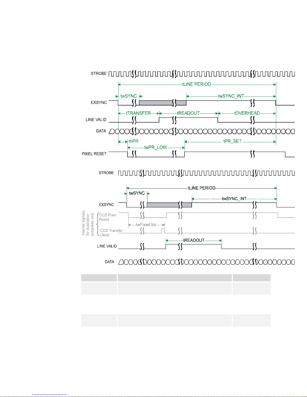
2.3 Camera Link Video Timing
Figure 6: Piranha 3 Overview Timing Showing Input and Output Relationships
Figure 7: Piranha 3 Fixed (Programmed) Integration Timing with External EXSYNC
Table 10: Piranha 3 Input and Output
03-032-10216-06 Teledyne DALSA

Piranha 3 User Manual
21
Symbol
Definition
Min (ns)
tLINE PERIOD
(t LP)
The minimum and maximum line times made up of
tTransfer, tREADOUT plus tOVERHEAD to meet
specifications.
53,190 (12k)
106,382 (8k)
tTransfer
The time from the reception of the falling ed ge of
EXSYNC to the rising edge of LVAL when pretrigger
is set to zero. Pretrigger reduces the number of clocks
to the risin g ed ge of LVAL bu t doesn’t ch ang e the tim e
to the first valid pixel. If the fixed integration time
mode of operation is available and selected then the
integration time is add ed to the specified value.
3,725 ±25
twFixed Int.
Fixed Integration Time mode of operation for variable
exsync frequency.
800
tREADOUT
Is the number of pixels per tap times the readout clock
period. Pretrigger = 0.
38,400 (12k)
25,600 (8k)
tOVERHEAD
Is the number of pixels that must elapse after the
falling edge of LVAL before the EXSYNC signal can be
asserted. This time is used to clamp the internal
analog electronics
425±25
thPR
Applies when the PRIN exposure control feature is
enabled . The PRIN signal must be held a minimum
time after the EXSYNC falling edge to avoid losing the
integrated charge
Don’t care
twPR_LOW
Minimum Low time to assure complete photosite reset
3,000
tPR_SET
The nominal time that the photo sites are integrating.
Clock synchronization will lead to integration time
jitter, which is shown in the specification as +/ values. The user should command times greater than
these to ensure proper charge transfer from the
photosites. Failure to meet this requirement may
result in blooming in the Horizontal Shift Register.
3,000
Teledyne DALSA 03-032-10216-06

Piranha 3 User Manual
22
03-032-10216-06 Teledyne DALSA

Piranha 3 User Manual
23
i
This chapter outlines the
more commonly used
commands. See section B2
All Available Commands
for a list of all available
commands.
Software Interface: How
to Control the Camera
All Piranha 3 camera features can be controlled through the serial interface. The camera
can also be used without the serial interface after it has been set up correctly. Functions
available include:
3
Controlling basic camera functions such as gain and sync signal source
Flat field correction
Generating a test pattern for debugging
The serial interface uses a simple ASCII-based protocol and the camera does not require
any custom software.
Serial Protocol Defaults
8 data bits
1 stop bit
No parity
No flow control
9.6kbps
Camera does not echo characters
Command Format
When entering commands, remember that:
A carriage return <CR> ends each command.
A space or multiple space characters separate parameters. Tabs or commas are invalid
parameter separators.
Upper and lowercase characters are accepted
The backspace key is supported
Teledyne DALSA 03-032-10216-06

Piranha 3 User Manual
24
Purpose:
Sets the speed in bps of the serial communication port.
Syntax:
sbr m
Syntax Elements:
m
Baud rate. Available baud rates are: 9600 (Default), 19200,
57600, and 115200.
Notes:
Power-on rate is always 9600 baud.
The rc (reset camera) command will not reset the camera to
the power-on baud rate and will reboot using the last used
baud rate.
Example:
sbr 57600
Syntax:
h
Syntax:
gh
Notes:
For more in form ation on the cam era’s ―get‖ com m an d s, refer to
section 3.6.6 Returning Camera Settings.
The camera will answ er each com m an d w ith either <CR><LF> ―OK >" or
<CR><LF>"Error xx: Error Message >" or ―Warning xx: Warning Message‖. Th e ">" is
always the last character sent by the camera.
The following parameter conventions are used in the manual:
i = integer value
f = real number
m = member of a set
s = string
t = tap id
x = pixel column number
y = pixel row number
Setting Baud Rate
Camera Help Screen
For quick help, the camera can return all available commands and parameters through the
serial interface.
There are two different help screens available. One lists all of the available commands to
configure camera operation. The other help screen lists all of the commands available for
retrieving camera p arameters (th ese ar e called ―get‖ com m and s).
To view the help screen listing all of the camera configuration commands, use the command:
To view a help screen listing all of the ―get‖ commands, use the command:
The camera configuration command help screen lists all available commands. Parameter
ranges displayed are the absolute maximum ranges available. Depending on the current
camera operating conditions, you may not be able to obtain these values. If this occurs,
values are clipped and the camera returns a warning message.
Some commands may not be available in your current operating mode. The help screen
displays NA in this case.
03-032-10216-06 Teledyne DALSA

Piranha 3 User Manual
25
P3 12k Example Help Screen
cao calibrate analog offset ti 0-8:0-255
ccf correction calibrate fpn
ccg calibrate camera gain iti 1-4:0-8:1024-4055
ccp correction calibrate prnu
clm camera link mode m 15/16/21/
cpa calibrate PRNU algorithm ii 1-4:1024-4055
css correction set sample m 256/512/1024/
dpc display pixel coeffs xx 1-12288:1-12288
els end of line sequence i 0-1
epc enable pixel coefficients ii 0-1:0-1
gcm get camera model
gcp get camera parameters
gcs get camera serial
gcv get camera version
get get values s
gfc get fpn coeff x 1-12288
gh get help
gl get line xx 1-12288:1-12288
gla get line average xx 1-12288:1-12288
gpc get prnu coeff x 1-12288
gsf get signal frequency i 1-4
gss get sensor serial
h help
lpc load pixel coefficients i 0-4
rc reset camera
rfs restore factory settings
roi region of interest xyxy 1-12288:1-1:1-12288:1-1
rpc reset pixel coeffs
rus restore user settings
sag set analog gain tf 0-8:-10.0-+10.0
sao set analog offset ti 0-8:0-255
sbr set baud rate m 9600/19200/57600/115200/
sdo set digital offset ti 0-8:0-2048
sem set exposure mode m 2/3/4/5/6/7/8/
set set exposure time f 3-3330 [uSec]
sfc set fpn coeff xi 1-12288:0-2048
sfr set fpn range xxi 1-8192:1-8192:0-2048
slt set lower threshold i 0-4095
sot set output throughput m 320/
spc set prnu coeff xi 1-12288:0-28671
spr set prnu range xxi 1-8192:1-8192:0-28671
spt set pretrigger i 0-16
ssb set subtract background ti 0-8:0-4095
ssf set sync frequency f 300-23619
ssg set system gain ti 0-8:0-65535
sut set upper threshold i 0-4095
svm set video mode i 0-2
ugr update gain reference
vt verify temperature
vv verify voltage
wfc write FPN coefficients i 1-4
wpc write PRNU coefficients i 1-4
wus write user settings
Teledyne DALSA 03-032-10216-06

Piranha 3 User Manual
26
Sensor Output Format
Data Processing
Camera Output Format
Set Frame/Line Rate ( )
Set Exposure Time ( )
ssf
set
Set Exposure Mode ( )sem
Region of Interest ( )
Correction Set Sample ( )
Enable Pixel Coefficients ( )
Set PRNU Coefficient ( )
Set FPN Coefficient ( )
roi
css
epc
spc
sfc
Set Analog Gain ( or )
Update Gain Reference ( )
Set Analog Offset ( )
Calibrate Analog Offset ( )
Calculate FPN ( )
Set Digital Offset ( )
Calculate PRNU ( )
Set Background Subtract ( )
Set Digital System Gain ( )
sag ccg
ugr
sao
cao
ccf
sdo
ccp
ssb
ssg
Camera Link Mode ( )
Camera Throughput ( )
Set Upper Threshold ( )
Set Lower Threshold ( )
clm
sot
sut
slt
Generate a Test Pattern ( )
End of Line Sequence ( )
Set Pretrigger ( )
svm
els
spt
Save Current User Settings ( )
Restore Previously Saved User Settings ( )
Save Current PRNU Coefficients ( )
Save Current FPN Coefficients ( )
Load Pixel Coefficients ( )
Reset Pixel Coefficients ( )
Restore Factory Settings ( )
Reboot Camera ( )
wus
rus
wpc
wfc
lpc
rpc
rfs
rc
Saving and Restoring Settings
Diagnostics
Get Line of Data ( )
Get an Average of Multiple Lines ( )
Display Pixel Coefficients ( )
Measure Internal Temperature ( )
Measure Input Voltage ( )
gl
gla
dpc
vt
vv
Get Commands
Other
Help ( )
Set Baud Rate ( )
h
sbr
Section 3.2
Section 3.3
Section 3.4
Section 3.5
Section 3.6
Introduction
Set PRNU Range ( )spr
Set FPN Range ( )sfr
3.1 Command Categories
The follow in g d iag ram cat egorizes and lists all of th e camera’s com m a nds. This ch ap ter is
organized by command category.
Figure 8: Command Categories
03-032-10216-06 Teledyne DALSA

Piranha 3 User Manual
27
1. You must first set the camera mode using the sem command.
2. Next, if using mode 2, 7 or 8 use the commands ssf and/ or set to set the line rate and
exposure time.
Purpose:
Sets the cam era’s exp osure mod e allow ing you to control you r
sync, exposure time, and line rate generation.
Syntax:
sem i
Syntax Elements:
i
Exposure mode to use. Factory setting is 7.
Notes:
Refer to Table 11: Piranha 3 Exposure Modes for a quick list
of available modes or to the following sections for a more
detailed explanation.
To obtain the current value of the exposure mode, use the
command gcp or get sem.
Related Commands:
ssf, set
Example:
sem 3
Mode
SYNC
PRIN
Description
2
Internal
Internal
Yes
Yes
Internal frame rate and exposure time.
Exposure mode enabled (ECE)
3
External
Internal
No
No
Maximum exposure time. Exposure
control disabled (ECD)
4
External
Internal
No
No
Smart EXSYNC. ECE.
5
External
External
No
No
External sync, external pixel reset.
ECE.
6
External
Internal
No
Yes
Fixed integration time. ECE.
7
Internal
Internal
Yes
No
Internal line rate, maximum exposure
time. ECD.
3.2 Sensor Output Format
3.2.1 Exposure Mode, Line Rate and Exposure Time
Overview
You have a choice of op erating in one of seven mod es. The cam era’s line rate
(synchronization) can be generated internally through the software command ssf or set
externally with an EXSYNC signal, depending on your mode of operation. To select how
you wan t th e camera’s lin e rate to be generated:
Setting the Exposure Mode
Table 11: Piranha 3 Exposure Modes
Programmable Line Rate Programmable Exposure Time
Teledyne DALSA 03-032-10216-06
Piranha 3 User Manual
28
Mode
SYNC
PRIN
Description
8
Internal
Internal
No
Yes
Maximum line rate for exposure time.
ECE.
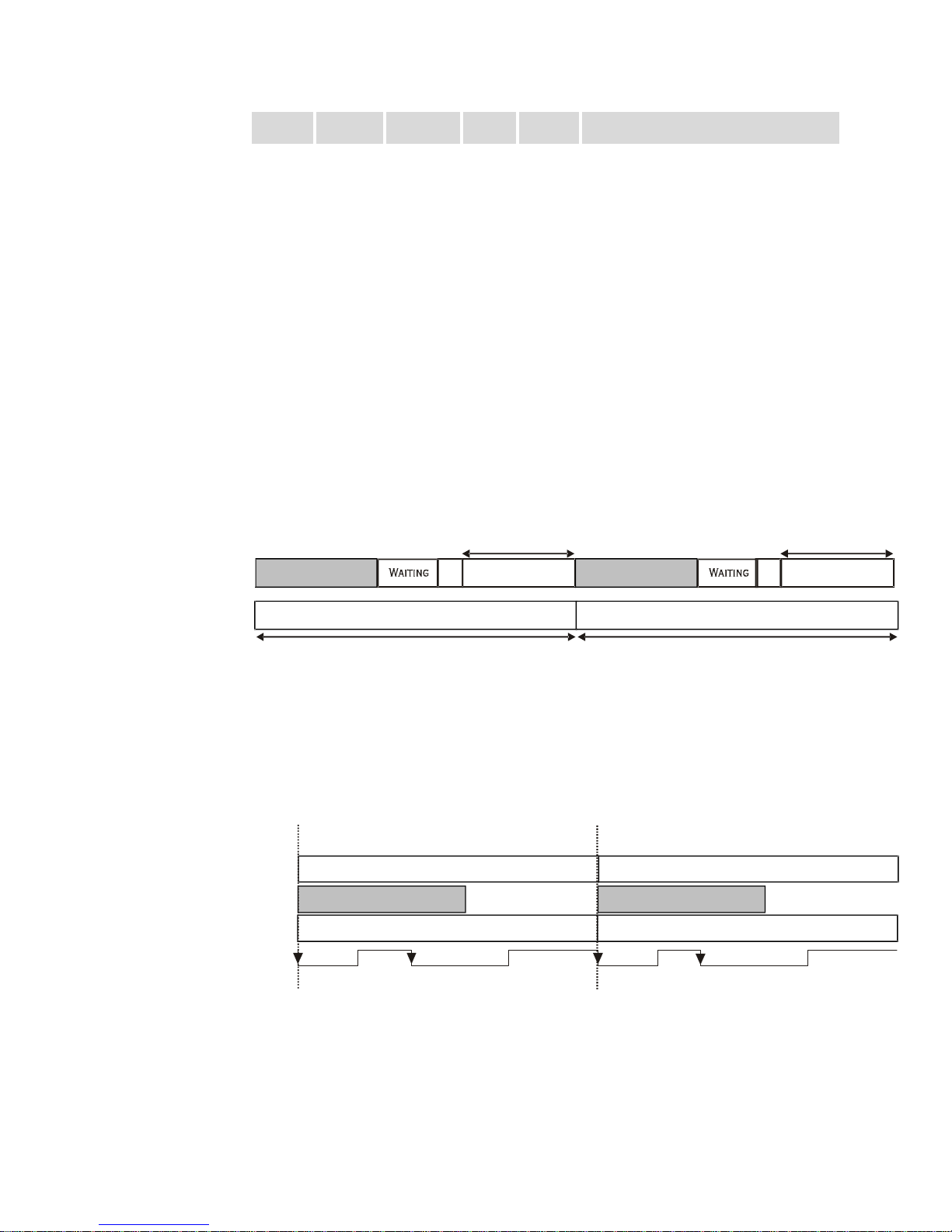
Programmable Period (set command)
Line Period
Readout
CR
Exposure Time
CR=Charge Reset
Line Period
Programmable Period
CR
Exposure Time
Programmable Period (ssf command)
Readout
Programmable Period
Line Period
Exposure Time
Line Period
Readout
Exposure Time
Falling Edge
Ignored During
Readout
Readout
Falling Edge
Ignored During
Readout
EXSYNC
Note: When setting the camera to external signal modes, EXSYNC and/or PRIN must be supplied.
Exposure Modes in Detail
Mode 2: Internally Programmable Line Rate and Exposure Time
Mode 2 operates at a user specified line rate and exposure time.
When setting the line rate (using the ssf command), exposure time will be reduced,
if necessary, to accommodate the new line rate. The exposure time will always be set
to the maximum time (line period – line transfer time – pixel reset time) for that line
rate when a new line rate requiring reduced exposure time is entered.
When setting the exposure time (using the set command), line time will be
increased, if necessary, to accommodate the exposure time. Under this condition, the
line time will equal the exposure time + line transfer time.
Example 1: Exposure Time less than Line Period
Mode 3: External Trigger with Maximum Exposure
Line rate is set by the period of the external trigger pulses. The falling edge of the external
trigger marks the beginning of the exposure.
Example 2: Line Rate is set by External Trigger Pulses.
03-032-10216-06 Teledyne DALSA
 Loading...