

Teledyne Linea, Dalsa Linea 2K CL, Dalsa Linea 4K CL User Manual
Linea
Camera User’s Manual
2k and 4k Monochrome CMOS Line Scan
sensors | cameras | frame grabbers | processors | software | vision solutions
03-032-20206-00
www.teledynedalsa.com

2 Linea 2K and 4K Monochrome Line Scan Camera User's Manual
North America
700 Technology Park Drive
Billerica, MA
USA, 01821
Tel: 978-670-2000
Fax: 978-670-2010
Email: Sales.Americas@teledynedalsa.com
Europe
Felix-Wankel-Str. 1
82152 Krailling
Germany
Tel: +49 89 89 54 57 3-80
Fax: +49 89 89 54 57 3-46
Email: Sales.Europe@teledynedalsa.com
Asia Pacific
Ikebukuro East 13F
3-4-3 Higashi Ikebukuro, Toshima-ku,
Tokyo
Japan
Tel: +81 3 5960 6353
Fax: +81 3 5960 6354
Email: Sales.Asia@teledynedalsa.com
© 2014 Teled yne DALSA, Inc. All information provided in this manual is believed to be accurate and reliable. No responsibility is
assumed by Teledyne DALSA for its use. Teledyne DALSA reserves the right to make changes to this information without notice.
Reproduction of this manual in whole or in part, by any means, is prohibited without prior permission having been obtained from
Teled yne DALSA.
About Teledyne Technologies and Teledyne DALSA, Inc.
Teled yne Technologies is a leading provid er of sophisticated electronic subsystems, instrumentation and communication product s,
engineered systems, a erosp ace engin es, an d energy a nd pow er genera tion sy stem s. Teled yn e Techno log ies‘ ope ra tio ns are prim arily
located in the United Sta tes, th e Un ited Kin gd o m an d Mexico. For more inform ation , visit Teled yne Technologies‘ websit e a t
www.teledyne.com.
Teled yne DALSA, a Teledyne Technologies company, is an international lead er in high performance digital imaging and
semiconductors with approximately 1,000 employees worldwide, headquartered in Waterloo, Ontario, Canada. Established in 1980,
the company designs, develops, manufactures and markets digital imaging prod ucts and solutions, in addition to provid ing MEMS
products an d serv ices. For mo re information , visit Teled yne D ALSA‘s websit e a t w w w.te led y ned alsa.com .
Support
For further information not included in this manual, or for information on Teledyne DALSA‘s extensive lin e of imag e sensing
products, please contact:
Document revised April 6, 2014.
03-032-20206-00 Teledyne DALSA

Linea 2K and 4K Monochrome Line Scan Camera User's Manual 3
Contents
1. System Precautions and Cleaning ___________________________________________________________________ 6
Precautions ..................................................................................................................................................... 6
Electrostatic Discharge and the CMOS Sensor ................................................................................................. 6
2. The Linea Camera ______________________________________________________________________________ 7
Camera Highlights ............................................................................................................................................................. 7
Camera Performance Specifications .................................................................................................................................. 8
Certifications and Compliance ........................................................................................................................................... 9
Supported Industry Standards ........................................................................................................................................... 9
Responsivity ....................................................................................................................................................................... 10
Mechanicals ........................................................................................................................................................................ 11
3. Quick, Simple Steps to Acquire an Image ______________________________________________________________ 12
4. Software and Hardware Setup______________________________________________________________________ 13
Recommended System Requirements ............................................................................................................. 13
Setup Steps: Overview ....................................................................................................................................................... 13
1. Install and Configure Frame Grabber and Software .................................................................................. 13
2. Connect Camera Link and Power Cables .................................................................................................... 13
3. Establish Communicating with the Camera ................................................................................................ 13
4. Operate the Camera ................................................................................................................................... 13
Step 1. Install and Configure the Frame Grabber and Software ....................................................................................... 14
Install Frame Grabber .................................................................................................................................... 14
Install Sapera LT and CamExpert GUI ............................................................................................................ 14
Step 2. Connect Data, Trigger, and Power Cables ............................................................................................................. 15
Data Connector: Camera Link ........................................................................................................................ 16
Camera Link Bit Definitions ............................................................................................................................ 18
Camera Link Drive Capability ......................................................................................................................... 19
Input Signals, Camera Link ............................................................................................................................ 19
Output Signals, Camera Link Clocking Signals............................................................................................... 19
Power Connector ............................................................................................................................................. 20
PoCL Power Over Camera Link....................................................................................................................... 20
LEDs ................................................................................................................................................................ 21
Step 3. Establish Communication with the Camera ........................................................................................................... 21
Power on the camera ...................................................................................................................................... 21
Connect to the frame grabber ......................................................................................................................... 21
Connect to the camera .................................................................................................................................... 21
Check LED Status ............................................................................................................................................ 22
Software Interface ........................................................................................................................................... 22
Using Sapera CamExpert with Linea Cameras .................................................................................................................. 23
CamExpert Panes ............................................................................................................................................ 24
4. Camera Operation ______________________________________________________________________________ 26
Factory Settings ................................................................................................................................................................. 26
Check Camera and Sensor Information ............................................................................................................................. 26
Verify Temperature and Voltage ....................................................................................................................................... 27
Teledyne DALSA 03-032-20206-00

4 Linea 2K and 4K Monochrome Line Scan Camera User's Manual
Saving and Restoring Camera Settings ............................................................................................................................. 27
Camera Link Configuration ............................................................................................................................................... 29
Trigger Modes .................................................................................................................................................................... 29
Exposure Controls .............................................................................................................................................................. 29
Exposure Modes in Detail .................................................................................................................................................. 30
Set Line Rate ..................................................................................................................................................................... 33
Set Exposure Time ............................................................................................................................................................. 36
Control Gain and Black Level ............................................................................................................................................ 36
Set Image Size ................................................................................................................................................................... 37
Set Baud Rate .................................................................................................................................................................... 37
Pixel Format ...................................................................................................................................................................... 38
Pixel Readout Direction (Mirroring Mode) ........................................................................................................................ 38
Resetting the Camera ........................................................................................................................................................ 38
Calibrating the Camera ..................................................................................................................................................... 39
Appendix A: GenICam Commands _____________________________________________________________________ 43
Camera Information Category ........................................................................................................................................... 43
Camera Information Feature Descriptions...................................................................................................... 44
Camera Configuration Selection Dialog ......................................................................................................... 47
Camera Power-up Configuration .................................................................................................................... 47
User Set Configuration Management ............................................................................................................. 47
Camera Control Category .................................................................................................................................................. 48
Camera Control Feature Descriptions ............................................................................................................. 49
Digital I/O Control Feature Descriptions ........................................................................................................ 50
Flat Field Category ............................................................................................................................................................ 51
Flat Field Control Feature Description ............................................................................................................ 52
Region of Interest (ROI) .................................................................................................................................. 53
Image Format Control Category ........................................................................................................................................ 53
Image Format Control Feature Description .................................................................................................... 54
Binning .............................................................................................................................................................................. 55
Area of Interest (AOI) Setup .............................................................................................................................................. 56
Transport Layer Control Category ..................................................................................................................................... 58
Transport Layer Feature Descriptions ............................................................................................................. 59
Acquisition and Transfer Control Category ........................................................................................................................ 59
Acquisition and Transfer Control Feature Descriptions................................................................................... 60
Serial Port Control Category .............................................................................................................................................. 61
Serial Port Control Feature Descriptions ........................................................................................................ 61
File Access Control Category .............................................................................................................................................. 62
File Access Control Feature Descriptions ......................................................................................................... 63
File Access via the CamExpert Tool ................................................................................................................. 64
Download a List of Camera Parameters ......................................................................................................... 65
Appendix B: ASCII Commands _______________________________________________________________________ 67
Appendix C: Error and Warning Messages _______________________________________________________________ 78
03-032-20206-00 Teledyne DALSA
Port Configuration .......................................................................................................................................... 68
Disabling the Esc Key for Direct Access to ASCII Commands ........................................................................... 69
Commands ...................................................................................................................................................... 69

Linea 2K and 4K Monochrome Line Scan Camera User's Manual 5
Appendix D: Quick Setup and Image Acquisition ___________________________________________________________ 80
Appendix E: The Sensor Window ______________________________________________________________________ 83
Cleaning and Protecting Against Dust, Oil, and Scratches .............................................................................. 83
Cleaning the Sensor Window .......................................................................................................................... 84
Appendix F: Camera, Frame Grabber Communication _______________________________________________________ 85
Setting Up Communication between the Camera and the Frame Grabber .................................................... 85
EMC Declaration of Conformity _______________________________________________________________________ 87
Revision History _________________________________________________________________________________ 88
Index ________________________________________________________________________________________ 89
Teledyne DALSA 03-032-20206-00

6 Linea 2K and 4K Monochrome Line Scan Camera User's Manual
1. System Precautions and
Cleaning
Precautions
Read these precautions and this manual carefully before using the camera.
Confirm that the cam era ‘s p ackagin g is und am aged b efore op ening it. If th e packaging is d am aged p lease
contact the related logistics personnel.
Do not open the housing of the camera. The warranty is voided if the housing is opened.
Keep th e camera‘s fron t p late temperature in a range of 0 °C to 65 °C during operation.
Do not operate the camera in the vicinity of strong electromagnetic fields. In addition, avoid elect rostatic
charging, violent vibration, and excess moisture.
To clean the device, avoid electrostatic charging by using a dry, clean absorbent cotton cloth dampened
with a small quantity of pure alcohol. Do not use methylated alcohol. To clean the surface o f the camera
housing, use a soft, dry cloth. To remove severe stains use a soft cloth dampened with a small quantity of
neutral detergent and then wipe dry. Do not use volatile solvents such as benzene and thinners, as they
can damage the surface finish. Further cleaning instructions are below.
Though this camera supports hot plugging, it is recom mended that you power down and disconnect
power to the camera before you add or replace system components.
Electrostatic Discharge and the CMOS Sensor
Image sensors and the camera bodies housing are susceptible to damage from electrostatic discharge
(ESD). Electrostatic charge introduced to the sensor window surface can induce charge buildup on the
underside of the window. The charge norm ally dissipates within 24 h ours and the sensor returns to
normal operation.
03-032-20206-00 Teledyne DALSA

Linea 2K and 4K Monochrome Line Scan Camera User's Manual 7
2. The Linea Camera
Camera Highlights
Teledyne DALSA introduces a new CMOS camera family with the 2K and 4K resolution Linea™
monochrome cameras. These new camera models employ Teledyne DALSA's single line, 7.04 µm x 7.04
µm pixel array, delivering both speed and responsivity at a competitive price.
These small, affordable, low power cameras are designed for applications such as materials grading and
inspection, transportation safety, automated optical inspection and general purpose machine vision.
Key Features
High speed: up to 80 kHz
2048 or 4096 pixel resolutions
Compact camera body
Programmability
Multiple regions of interest for calibration and data reduction
8 bit or 12 bit output
Small flat field and lens shading correction
8 programmable coefficient sets
GenICam or ASCII compliant interfacing
Applications
Automated optical inspection
Security systems
High performance sorting systems
Materials grading and inspection systems
Web inspection
General purpose machine vision
Teledyne DALSA 03-032-20206-00
8 Linea 2K and 4K Monochrome Line Scan Camera User's Manual
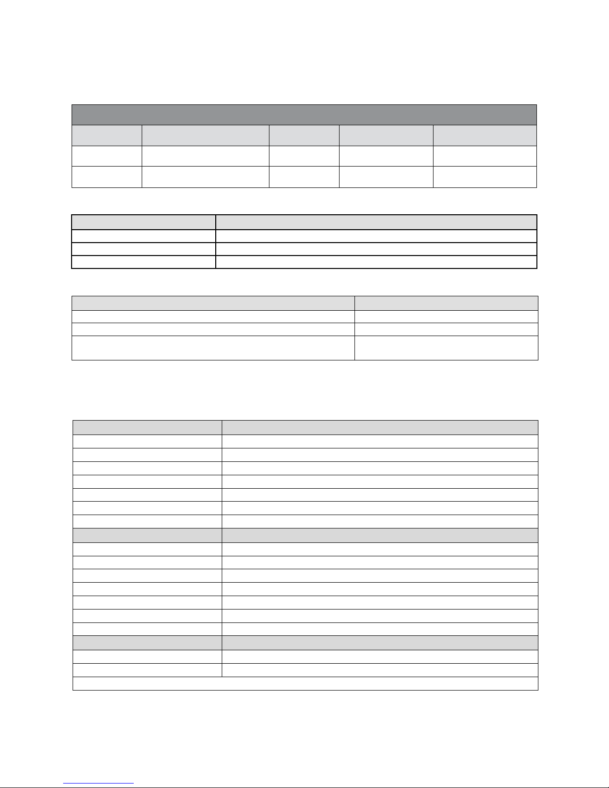
Linea Dual Line Model Comparison
Camera
Part Number
Resolution
Max. Line Rate
Pixel Size
Linea 2K CL
LA-CM -02K08A-00-R
2048 x 1
80 kHz
7.04 µm x 7.04 µm
Linea 4K CL
LA-CM -04K08A-00-R
4096 x 1
80 kHz
7.04 µm x 7.04 µm
Part No.
Description
AC-LC-00001-00-R
M42 x 1 to C-mount adapter 12 mm BFD lens
AC-LA-00115-A0-R
M42 x 1 to F-mount ad apter 12 mm BFD lens, heavy duty with clip
AC-MS-00108-01-R
Heat sink (LA 4K / 2K)
Software
Product Number / Version Number
Camera firmware
Embedded within camera
GenICam™ support (XML camera description file)
Embedded within camera
Sapera LT, including CamExpert GUI application and
GenICam for Camera Link imaging driver
Version 7.30 or later
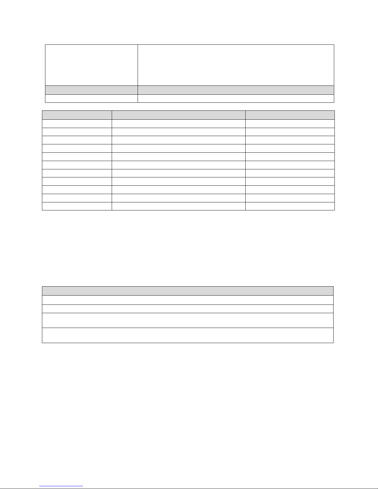
Specifications
Performance
Imager Format
High speed CMOS line scan
Resolution
2048 or 4096 pixels
Pixel Size
7.04 µm x 7.04 µm
Pixel Fill Factor
100 %
Line Rate
Up to 80 kHz
Exposure Time
4 µs to 3 ms
Bit Depth
8 bit or 12 bit, selectable
Connectors and Mechanicals
Control & Data Interface
Base, Med ium, and Full Camera Link configurations (2 x SDR-26)
Power Connector
Hirose 6-pin male circular
Power Supply
+ 5 V to + 24 V DC (+4.8 V to +25.2 V maximum limits)
Power Dissipation
< 4.5 W
Size
62 mm (W) x 62 mm (H) x 31 mm (D)
Mass
< 190 g
Operating Temp
0 °C to 65 °C, front plate temperature
Optical Interface
Lens Mount
M42 x 1, C-mount adapter available
Sensor to Camera Front Distance
12 mm
Sensor Alignment (aligned to sides of camera)
Models and Accessories
Table 1: Camera Models Comparison
Table 2: Optional Lens Mount Accessories
Table 3: Software
Camera Performance Specifications
Table 4: Camera Performance Specifications
03-032-20206-00 Teledyne DALSA
Linea 2K and 4K Monochrome Line Scan Camera User's Manual 9
y (parallelism)
x
y
z
z
0.08° or 100 µm
± 300 µm
± 300 µm
± 300 µm
± 0.3°
Compliance
Regulatory Compliance
CE, FCC, and RoHS; GenICam
Operating Ranges
Performance
Notes
Dynamic Range
> 60 dB
Random Noise
< 3.75 DN * rms
FFC enabled
Broadband Responsivity
320 DN / (nJ / cm2)
Gain
1x to 10x Nominal range
DC Offset
7 DN
FFC enabled
PRNU
< 1.5% @ 50% Sat
FPN
< 7 DN
SEE
12.5 nJ / cm2
NEE
11.7 pJ / cm2
Antiblooming
> 100 x Saturation
Integral non-linearity
1.5 % DN
Compliance
EN 55011, FCC Part 15, CISPR 11, and ICES-003 Class A Radiated Emissions Requirements
EN 55024 and EN 61326-1 Immunity to Disturbance
RoHS per EU Directive 2011/ 65/ EC and WEEE per EU Directive 2002/ 96/ EC and China Electronic Industry
Standard SJ/ T11364-2006
GenICam XML Description File, Sup er set of th e GenICam™ Stan d a rd Fea tu res N am in g Co n ven tion specificatio n
V1.5, Camera Link Serial Comm u n ication: Gen ICam ™ Generic Control Protocol (GenCP V1.0)
*DN = digital number
Test Conditions:
Values measured using 12-bit, 1x gain.
10 kHz line rate
Light source: broadband, quartz halogen, 3250 K with 700 nm IR cut-off filter.
Front plate temperature: 45º C
Certifications and Compliance
Supported Industry Standards
GenICam™
Linea cameras are GenICam com p lian t. Th ey imp lem ent a su per set of the GenICam™ Stand a rd Featu r es
Naming Convention specification V1.5.
This description takes the form of an XML device description file respecting the syntax defined by the
GenApi module of the GenICam™ specification. The camera uses the GenICam ™ Gen eric Control
Protocol (GenCP V1.0) to communicate over the Camera Link serial port.
Teledyne DALSA 03-032-20206-00
10 Linea 2K and 4K Monochrome Line Scan Camera User's Manual
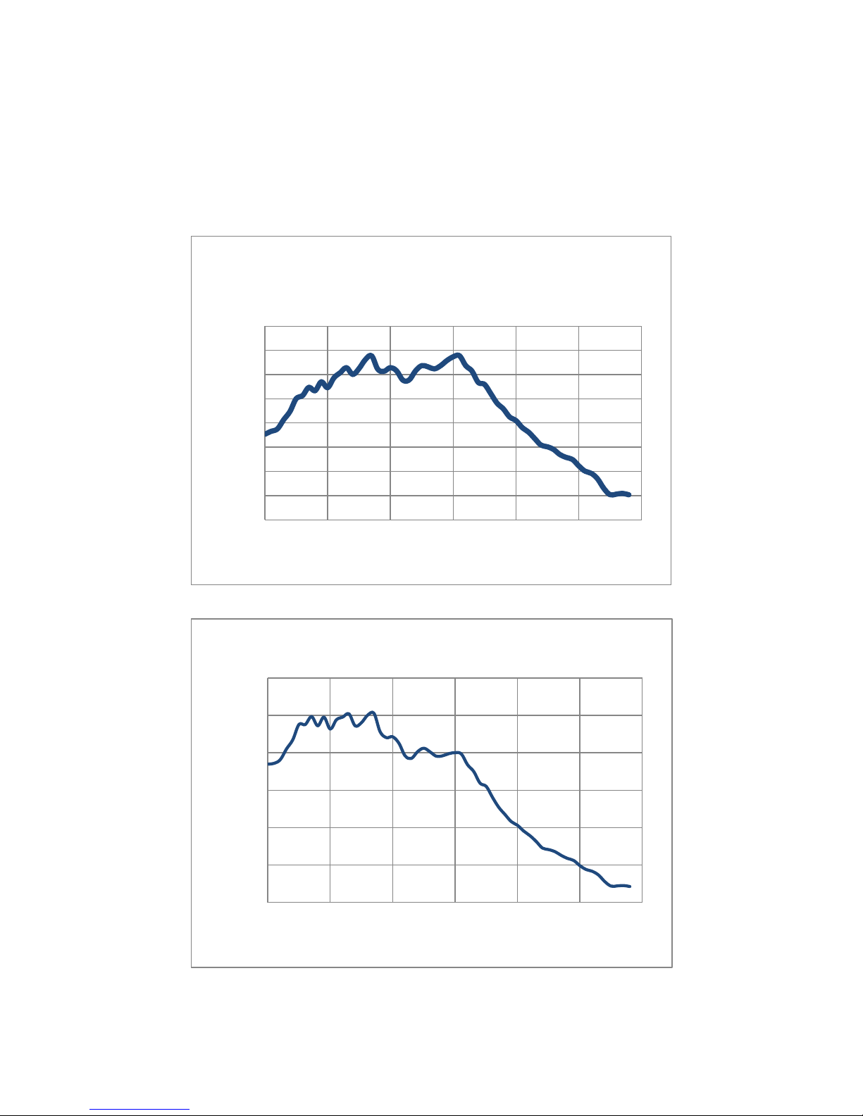
0
50
100
150
200
250
300
350
400
400 500 600 700 800 900 1000
Responsivity (DN/nJ/cm^2)
Wavelength (nm)
Linea 2k and 4K Responsivity
(12 bit, 1x Gain)
0%
10%
20%
30%
40%
50%
60%
400 500 600 700 800 900 1000
QE (%)
Wavelength (nm)
Linea 2K and 4K QE
For more information see www.genicam.org.
Responsivity
The responsivity graph describes the sensor response to different wavelengths of light (excluding lens
and light source characteristics).
Figure 1: Spectral Responsivity vs. Wavelength
Figure 2: QE (%) vs. Wavelength
03-032-20206-00 Teledyne DALSA

Linea 2K and 4K Monochrome Line Scan Camera User's Manual 11
Mechanicals
[INSERT PDF HERE]
Figure 3: Camera Mechanicals
Teledyne DALSA 03-032-20206-00

12 Linea 2K and 4K Monochrome Line Scan Camera User's Manual
3. Quick, Simple Steps to
Acquire an Image
For users who are familiar with Camera Link cameras, have a basic understanding of their imaging
requirements, and who are primarily interested in evaluating the Linea camera, an overview of the steps
required to get this camera operational and acquiring images quickly can be found in Appendix D: Quick
Setup and Image Acquisition.
03-032-20206-00 Teledyne DALSA

Linea 2K and 4K Monochrome Line Scan Camera User's Manual 13
4. Software and Hardware Setup
Recommended System Requirements
To achieve best system performance, the following minimum requirements are recommended:
High bandwidth frame grabber, e.g. TeledyneDALSA Xtium -CL PX4 frame grabber (Part # OR-
Y4C0-XPX00): http:/ / www.teledynedalsa.com/ imaging/ products/ fg/ OR-Y4C0-XPX00/ .
Operating systems: Windows XP / Vista / 7, 32 / 64-bit.
Setup Steps: Overview
Take the following steps in order to setup and run your camera system. They are described briefly below
and in more detail in the sections that follow.
1. Install and Configure Frame Grabber and Software
We recommend the Xtium-CL PX4 frame grabber or equivalent, described in detail on the
teledynedalsa.com site here. Follow the m an ufactu rer‘s installat ion instructions.
A Gen ICam ™ comp lian t XML d evice description file is em bed d ed w ithin the camera firmw are allowing
GenICam ™ com p lian t ap p lication to know the cam era‘s capabilities imm ed iately after con n ection.
Installing SaperaLT gives you access to the CamExpert GUI, a GenICam ™ com pliant ap p lication .
2. Connect Camera Link and Power Cables
Connect the Camera Link cables from the camera to the computer.
Connect a power cable from the camera to a power supply that can provide a constant voltage
between +5 VDC and +24 VDC.
3. Establish Communicating with the Camera
Start the GUI and establish communication with the camera.
ASCII Commands
As an alternative to the CamExpert (or equivalent) GUI, you can communicate with this camera using
ASCII-based commands. Open up an ASCII interface and press the ESC key, then the communication
mode will be switched into the ASCII command mode other than the GenICam mode. A complete list of
the commands and a description of how to access them can be found in Appendix B: ASCII Commands.
4. Operate the Camera
At this point you will be ready to start operating the camera in order to acquire images, set camera
functions, and save settings.
Teledyne DALSA 03-032-20206-00

14 Linea 2K and 4K Monochrome Line Scan Camera User's Manual
Step 1. Install and Configure the Frame Grabber
and Software
Install Frame Grabber
Install a Full configuration Camera Lin k fram e grabber accor d ing to th e m anu facture r‘s descrip tion .
We recommend the Xtium-CL PX4 frame grabber or equivalent, described in detail on the
teledynedalsa.com site here.
Install Sapera LT and CamExpert GUI
Communicate with the camera using a Camera Link-compliant interface. We recommend you use
CamExpert. CamExpert is the camera interfacing tool supported by the Sapera library and comes
bundled with SaperaLT. Using CamExpert is the simplest and quickest w ay to send commands to and
receive information from the camera.
Camera Link Control Communications
The Linea fam ily of cam eras are Gen ICam ™ com p lian t. Sap era u se s th e GenICam ™ Generic Con trol
Protocol (GenCP V1.0) to communicate with the camera over the Camera Link serial port. When
communications are first established Sapera will when connecting for the first time download the
GenICam ™ XML D escrip tion file. Th is file d etails how to access and control the cam era.
03-032-20206-00 Teledyne DALSA
Linea 2K and 4K Monochrome Line Scan Camera User's Manual 15
A
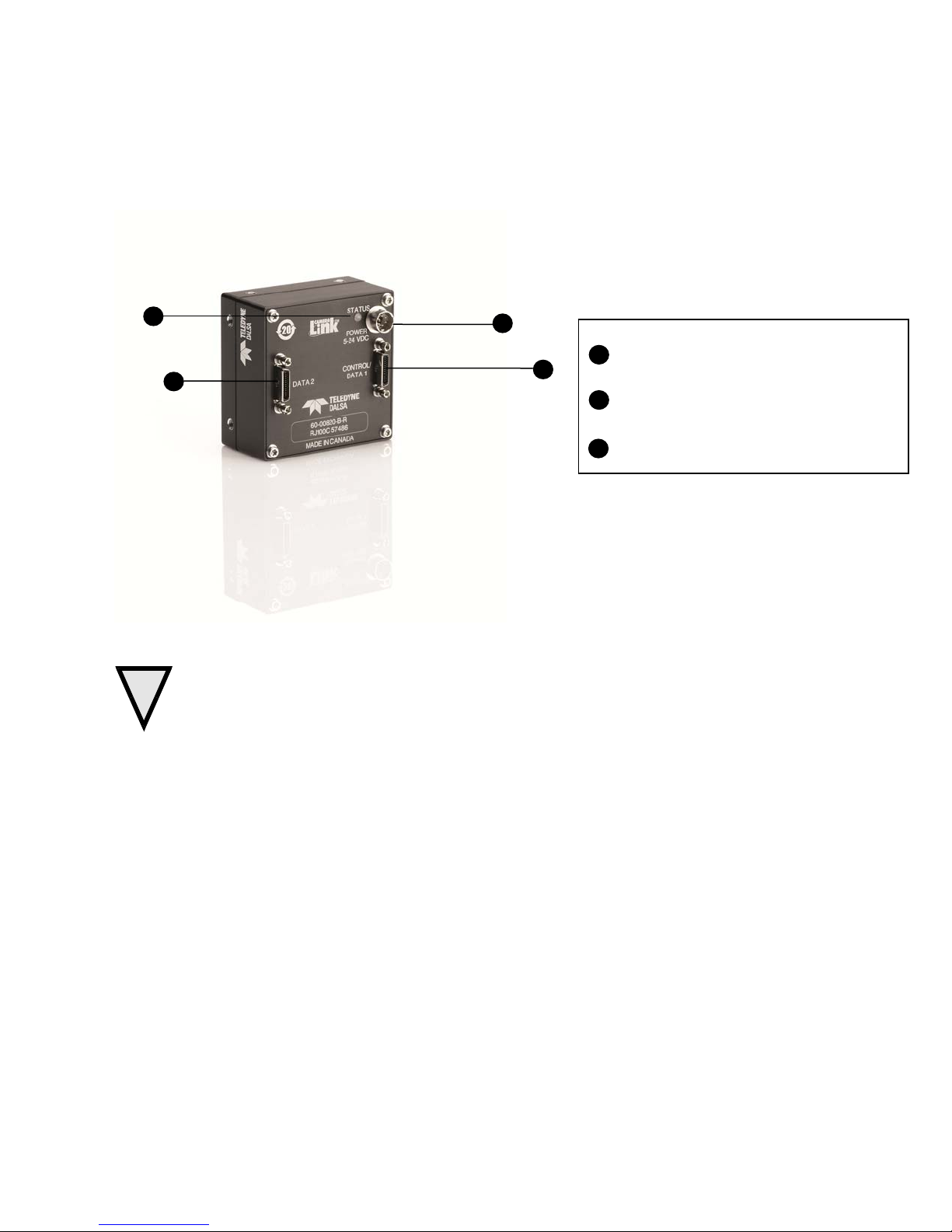
Step 2. Connect Data, Trigger, and Power Cables
Note: the use of cables types and lengths other than those specified may result in increased emission or
decreased immunity and performance of the camera.
C
Power
A
+5V to +24V DC Hirose 6-pin
Control & Data
Camera Link 26-pin SDR26 connectors
B
Status
Diagnostic LED
C
B
B
Figure 4: Input and Output, Trigger, and Power Connectors
WARNING! Grounding Instructions
!
Static electricity can damage electronic components. It’s critical that you discharge any static
electrical charge by touching a grounded surface, such as the metal computer chassis, before
handling the camera hardware.
Teledyne DALSA 03-032-20206-00
16 Linea 2K and 4K Monochrome Line Scan Camera User's Manual
Data 2
Control / Data 1
Camera
Connector
Right Angle
Frame Grabber
Connector
Channel Link
Signal
Camera
Connector
Right Angle
Frame Grabber
Connector
Channel Link
Signal
1 1 inner shield
1 1 PoCL
14
14
inner shield
14
14
inner shield
2
25
Y0- 2 25
X0-
15
12
Y0+
15
12
X0+ 3 24
Y1- 3 24
X1-
16
11
Y1+
16
11
X1+ 4 23
Y2- 4 23
X2-
17
10
Y2+
17
10
X2+ 5 22
Yclk-
5
22
Xclk-
18 9 Yclk+
18 9 Xclk+
6
21
Y3- 6 21
X3-
19 8 Y3+
19 8 X3+ 7 20
100 ohm
7
20
SerTC+
20 7 terminated
20 7 SerTC-
8
19
Z0- 8 19
SerTFG-
21 6 Z0+
21 6 SerTFG+
9
18
Z1- 9 18
CC1-
22 5 Z1+
22 5 CC1+
10
17
Z2-
10
17
CC2+
23 4 Z2+
23 4 CC2-
11
16
Zclk-
11
16
CC3-
24 3 Zclk+
24 3 CC3+
12
15
Z3-
12
15
CC4+
25 2 Z3+
25 2 CC4-
13
13
inner shield
13
13
inner shield
26
26
inner shield
26
26
PoCL
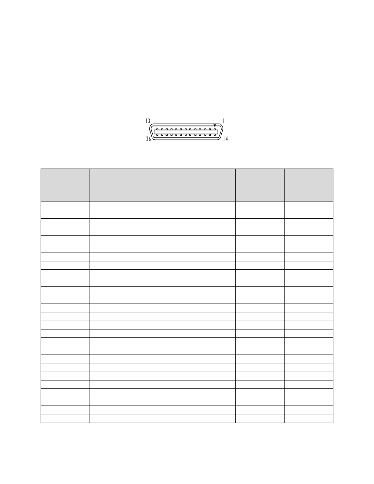
Data Connector: Camera Link
The camera uses two Camera Link SDR26 cables transmitting the Camera Link Base, Medium, or Full
configuration. The figure below shows the SDR26 Camera Link Connector and the tables that follow list
the Camera Link Base, Medium, and Full configurations.
For detailed information on Camera Link please refer to the Camera Link Road Map available from th e
Knowledge Center on the Teledyne DALSA Web site:
(http:/ / www.teledynedalsa.com/ mv/ knowledge/ appnotes.aspx).
Figure 5. Camera Link Connector
*Exterior Overshield is connected to the shells of the connectors on both ends. Unused pairs should be terminated in 100 ohms at
both ends of the cable. Inner shield is connected to signal ground inside camera
03-032-20206-00 Teledyne DALSA

Linea 2K and 4K Monochrome Line Scan Camera User's Manual 17
8 bits Camera Link Full Configuration
Connector 1: Channel link X
Connector 2: Channel link Y
Connector 3: Channel link Z
Camera/Frame
Grabber Pin
Bit Name
Camera/Frame
Grabber Pin
Bit Name
Camera/Frame
Grabber Pin
Bit Name
Tx0/Rx0
D0(0)
Tx0/Rx0
D3(0)
Tx0/Rx0
D6(0)
Tx1/Rx1
D0(1)
Tx1/Rx1
D3(1)
Tx1/Rx1
D6(1)
Tx2/Rx2
D0(2)
Tx2/Rx2
D3(2)
Tx2/Rx2
D6(2)
Tx3/Rx3
D0(3)
Tx3/Rx3
D3(3)
Tx3/Rx3
D6(3)
Tx4/Rx4
D0(4)
Tx4/Rx4
D3(4)
Tx4/Rx4
D6(4)
Tx5/Rx5
D0(7)
Tx5/Rx5
D3(7)
Tx5/Rx5
D6(7)
Tx6/Rx6
D0(5)
Tx6/Rx6
D3(5)
Tx6/Rx6
D6(5)
Tx7/Rx7
D1(0)
Tx7/Rx7
D4(0)
Tx7/Rx7
D7(0)
Tx8/Rx8
D1(1)
Tx8/Rx8
D4(1)
Tx8/Rx8
D7(1)
Tx9/Rx9
D1(2)
Tx9/Rx9
D4(2)
Tx9/Rx9
D7(2)
Tx10/Rx10
D1(6)
Tx10/Rx10
D4(6)
Tx10/Rx10
D7(6)
Tx11/Rx11
D1(7)
Tx11/Rx11
D4(7)
Tx11/Rx11
D7(7)
Tx12/Rx12
D1(3)
Tx12/Rx12
D4(3)
Tx12/Rx12
D7(3)
Tx13/Rx13
D1(4)
Tx13/Rx13
D4(4)
Tx13/Rx13
D7(4)
Tx14/Rx14
D1(5)
Tx14/Rx14
D4(5)
Tx14/Rx14
D7(5)
Tx15/Rx15
D2(0)
Tx15/Rx15
D5(0)
Tx15/Rx15
Not Used
Tx16/Rx16
D2(6)
Tx16/Rx16
D5(6)
Tx16/Rx16
Not Used
Tx17/Rx17
D2(7)
Tx17/Rx17
D5(7)
Tx17/Rx17
Not Used
Tx18/Rx18
D2(1)
Tx18/Rx18
D5(1)
Tx18/Rx18
Not Used
Tx19/Rx19
D2(2)
Tx19/Rx19
D5(2)
Tx19/Rx19
Not Used
Tx20/Rx20
D2(3)
Tx20/Rx20
D5(3)
Tx20/Rx20
Not Used
Tx21/Rx21
D2(4)
Tx21/Rx21
D5(4)
Tx21/Rx21
Not Used
Tx22/Rx22
D2(5)
Tx22/Rx22
D5(5)
Tx22/Rx22
Not Used
Tx23/Rx23
Not Used
Tx23/Rx23
Not Used
Tx23/Rx23
Not Used
Tx24/Rx24
LVAL
Tx24/Rx24
LVAL
Tx24/Rx24
LVAL
Tx25/Rx25
FVAL
Tx25/Rx25
FVAL
Tx25/Rx25
FVAL
Tx26/Rx26
Not Used
Tx26/Rx26
Not Used
Tx26/Rx26
Not Used
Tx27/Rx27
D0(6)
Tx27/Rx27
D3(6)
Tx27/Rx27
D6(6)
Tap 1 bits are D0(x)...Tap 8 bits are D7(x)
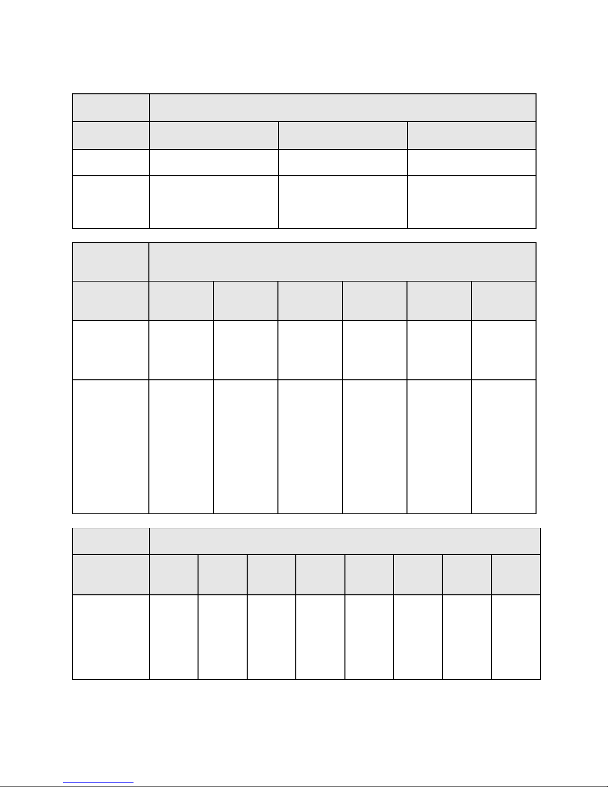
Full Configuration
Teledyne DALSA 03-032-20206-00
18 Linea 2K and 4K Monochrome Line Scan Camera User's Manual
BASE
Configuration
T0
Pixel Format
Port A
Bits 0 thru 7
Port B
Bits 0 thru 7
Port C
Bits 0 thru 7
Mono 8
Tap 1 LSB..Bit 7
Pixels (1, 3, 5, ... 4093, 4095)
Tap 2 LSB..Bit7
Pixels (2, 4, 6, ... 4094, 4096)
xxxxxxx
Mono 12
Tap 1 LSB.. Bit 7
Pixels (1, 3, 5, ... 84093, 4095)
Tap 1 Bits 8,9,10,11
Pixels (1, 3, 5, ... 4093,4095)
Tap 2 Bits 8,9,10,11
Pixels (2,4,6, ... 4094, 4096)
Tap 2 LSB..Bit 7
Pixels (2,4,6, ... 4094, 4096)
Medium
Configuratio
n
T0
Pixel Format
Port A
Bits 0 thru
7
Port B
Bits 0 thru
7
Port C
Bits 0 thru
7
Port D
Bits 0 thru
7
Port E
Bits 0 thru
7
Port F
Bits 0 thru
7
Mono 8
Tap 1
LSB..Bit 7
Pixels (1, 5, 9,
... 4089, 4093)
Tap 2
LSB..Bit 7
Pixels (2, 6,
10, ... 4090,
4094)
Tap 3
LSB..Bit 7
Pixels (3, 7,
11, ... 4091,
4095)
Tap 4
LSB...Bit 7
Pixels (4, 8,
12, ... 4092,
4096)
xxxxxxxx
Xxxxxxxx
Mono 12
Tap 1
LSB.. Bit 7
Pixels (1, 5, 9,
... 4091, 4095)
Tap 1
Bits 8,9,10,11
Pixels (1, 5, 9,
... 4091, 4095)
Tap 2
Bits 8,9,10,11
Pixels (2, 6,
10, ... 4092,
4096)
Tap 2
LSB..Bit 7
Pixels (2, 6,
10, ... 4092,
4096)
Tap 4
LSB…Bit 7
Pixels (4, 8,
12, ... 4090,
4094)
Tap 3
LSB…Bit 7
Pixels (3, 7,
11, ... 4089,
4093)
Tap 3
Bit 8,9,10,11
Pixels (3, 7,
11, ... 4089,
4093)
Tap 4
Bits 8,9,10,11
Pixels (4, 8,
12, ... 4090,
4094)
Full
Configuration
T0
Pixel Format
Port A
LSB…Bit
7
Port B
LSB…Bit
8
Port C
LSB…Bit
8
Port D
LSB…Bit
8
Port E
LSB…Bit
8
Port F
LSB…Bit
8
Port G
LSB…Bit
8
Port H
LSB…Bit
8
Mono 8
Tap 1
LSB…
Bit 7
Pixels (1,
9, 17, ...
4081,
4089)
Tap 2
LSB…
Bit 7
Pixels (2,
10, 18, ...
4082,
4090)
Tap 3
LSB…
Bit 7
Pixels (3,
11, 19, ...
4083,
4091)
Tap 4
LSB…
Bit 7
Pixels (4,
12, 20, ...
4084,
4092)
Tap 5
LSB…
Bit 7
Pixels (5,
13, 21, ...
4085,
4093)
Tap 6
LSB…
Bit 7
Pixels (6,
14, 22, ...
4086,
4094)
Tap 7
LSB…Bit
7
Pixels (7,
15, 23, ...
4087,
4095)
Tap 8
LSB…
Bit 7
Pixels (8,
16, 24, ...
4088,
4096)
Camera Link Bit Definitions
03-032-20206-00 Teledyne DALSA

Linea 2K and 4K Monochrome Line Scan Camera User's Manual 19
Signal
Configuration
CC1
EXSYNC
CC2
Spare
CC3
Spare
CC4
Spare
Cable Length
Frame Grabber (Manufacturer / Part Number)
7 meter
TeledyneDALSA Xcelera-CL PX4 / OR-X4C0-XPF00
10 meter
TeledyneDALSA Xtium -CL PX4 / OR-Y4C0-XPX00
Table 5: Camera Link Bit Definitions
Table 6: Camera Control Configuration
For additional Camera Link documentation refer to the Teledyne DALSA Web site‘s Knowledge Center
application notes.
Camera Link Drive Capability
The camera link cable drive capability on LA-4K/ 2K cameras has been improved to reach up to 10
meters. This capability has been tested using a number of frame grabbers (listed in the table below) and
was tested using standard Cam era Link cables. The cable length drive achieved on the various frame
grabbers is as follows:
Table 7: Cable Length and Frame Grabber Pairings
Input Signals, Camera Link
The camera accepts control inputs through the Camera Link SDR26F connector. The camera ships in
internal sync, and internally programmed integration.
EXSYNC (Line Readout Trigger)
Line rate can be set internally using the GenICam features. The external control signal EXSYNC is
optional and enabled through the user interface. This camera uses the falling edge of EXSYNC to trigger
pixel readout.
The EXSYNC signal tells the camera when to integrate and readout the image. It can be either an
internally generated signal by the camera, or it can be supplied externally via the serial interface.
Depending upon the mode of op eration the high time of the EXSYNC signal can represent the integration
period.
Note: Th e EXSYNC sig n al is m easu red at CC1 and w ill g ive a ―tru e‖ m easu rem en t (i.e. within th e
measurement resolution of 25 ns) even though the camera will only trigger at a maximum of 80 kHz.
Output Signals, Camera Link Clocking Signals
These signals indicate when data is valid, allowing you to clock the data from the camera to your
acquisition system. These signals are part of the Camera Link configuration and you should refer to the
Camera Link Implementation Road Map, available at our Knowledge Center, for the standard location of
these signals.
Teledyne DALSA 03-032-20206-00
20 Linea 2K and 4K Monochrome Line Scan Camera User's Manual
!
Clocking Signal
Indicates
LVAL (high)
Outputting valid line
DVAL
Not used
STROBE (rising edge)
Valid data
FVAL
Set to 0
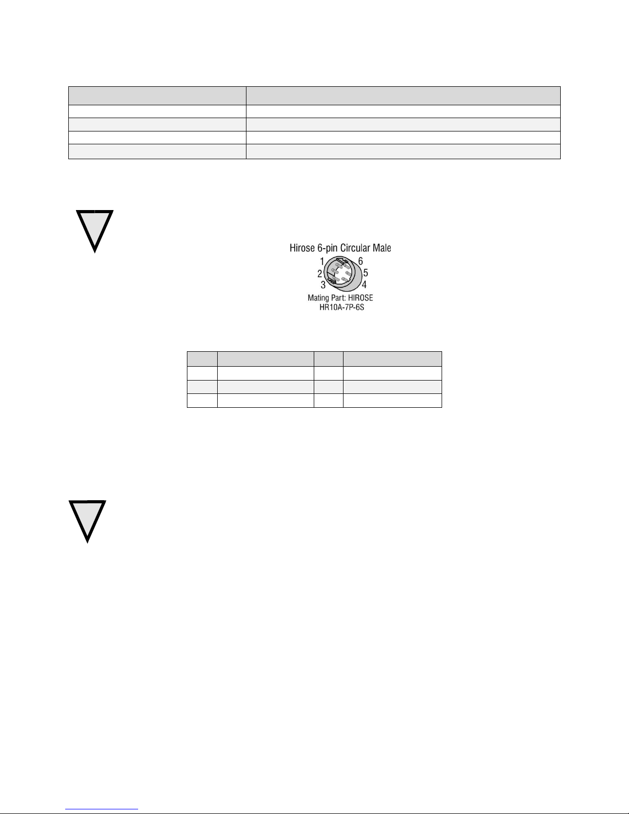
Pin
Description
Pin
Description
1
+5 V to +24 V DC
4
GND
2
+5 V to +24 V DC
5
GND
3
+5 V to +24 V DC
6
GND
!
Power Connector
WARNING: It is extremely important that you apply the appropriate voltages to your camera.
Incorrect voltages may damage the camera. Input voltage requirement: +5 VDC to +24 VDC, 1
Amp. Before connecting power to the camera, test all power supplies.
Figure 6: 6-pin Hirose Circular Male Power Plug—Power Connector
Table 8. Power Plug Pinout
The camera requires a single voltage input +5 VDC to +24 VDC. The camera meets all performance
specifications using standard switching power supplies, although well-regulated linear supplies provide
optimum performance.
WARNING: When setting up the camera’s power supplies follow these guidelines:
Apply the appropriate voltages.
Protect the camera with a 2 amp slow-blow fuse between the power supply and the camera.
Do not use the shield on a multi-conductor cable for ground.
Keep leads as short as possible in order to reduce voltage drop.
Use high-quality supplies in order to minimize noise.
Note: If your power supply does not meet these requirements, then the camera performance specifications are not
guaranteed.
PoCL Power Over Camera Link
The Linea 2K and 4K Camera Link cameras are PoCL compatible, but not compliant with the full PoCL
specification as their operation is dependent on the frame grabber used. These cameras exceed the 4 W
PoCL power specification by 0.35 W, but some frame grabbers, such as the Xtium frame grabber from
Teledyne Dalsa, are able to supply sufficient power for the camera‘s operation .
PoCL can be enabled from within CamExpert. Be sure to connect the power supply to the Xtium frame
gabber in the PC.
03-032-20206-00 Teledyne DALSA

Linea 2K and 4K Monochrome Line Scan Camera User's Manual 21
Color of Status LED
Meaning
Off
No power or hardware malfunction
Blinking
Powering up or calibrating
Green
Ready
Red
Error. Check the built-in self test (BiST) register for the specific error
PoCL power can only be supplied through the Data 1 (base) camera link port.
LEDs
The camera is equipped with an LED on the back to display the operational status of the camera. The
table below summarizes the operating states of the camera and the corresponding LED states. When more
than one condition is active, the LED indicates the condition with the highest priority.
Step 3. Establish Communication with the
Camera
Power on the camera
Turn on the camera‘s power supply. You may have to wait while the camera readies itself for operation.
The camera must boot fully before it will be recognized by the GUI—the LED shines green once the
camera is ready.
Connect to the frame grabber
1. Start Sapera CamExpert (or equivalent Camera Link compliant interface) by double clicking the
desktop icon created during the softw are installation.
2. CamExpert will search for installed Sapera devices. In the Devices list area on the left side, the
connected frame grabber will be shown.
3. Select the frame grabber device by clicking on the name.
Note: The first time you set up the camera you will need to establish a communication link between the
camera and frame grabber.
Connect to the camera
1. Start a new Sapera CamExpert application (or equivalent Camera Link compliant interface) by
double clicking the desktop icon created during the software installation.
2. In the Devices list area on the left side, select the COM port below the Camera Link label.
Teledyne DALSA 03-032-20206-00
22 Linea 2K and 4K Monochrome Line Scan Camera User's Manual
Figure 7. CamExpert GUI showing connected camera
Check LED Status
If the camera is operating correctly at this point, the diagnostic LED will shine green.
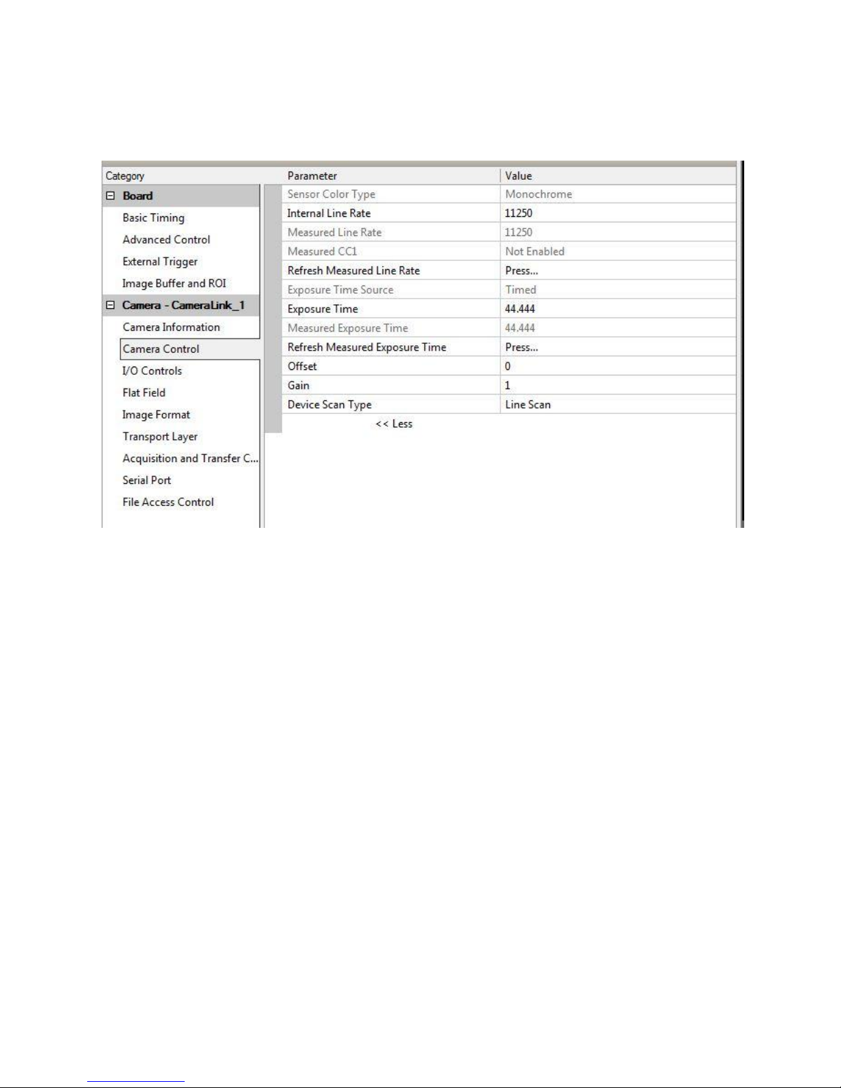
Software Interface
All the camera features can be controlled through the CamExpert interface. For example, under the
Camera Control menu in the camera window you can control the line rate and exposure times.
03-032-20206-00 Teledyne DALSA
Linea 2K and 4K Monochrome Line Scan Camera User's Manual 23
A note on the CamExpert examples shown here: The examples shown for illustrative purposes and may
not entirely reflect the features and parameters available from the camera model used in your
application.
At this p oin t you r h ost an d cam era sy stem shou ld be setup and you can verify th e cam er a‘s op eration by
retr ieving a test p attern and settin g the camera‘s trig ger and exp osu re time.
Using Sapera CamExpert with Linea Cameras
CamExpert is the camera interfacing tool supported by the Sapera library. When used with a Linea
camera, CamExpert allows a user to test all camera operating modes. Additionally CamExpert saves the
camera user settings configuration to the camera or saves multiple configurations as individual camera
parameter files on the host system (*.ccf). Cam Expert can also b e used to u pgrad e the cam era‘s so ftw are.
An important component of CamExpert is its live acquisition display window which allows immediate
verification of timing or control parameters without the need to run a separate acquisition program.
For context sensitive help, click on the button then click on a camera configuration parameter. A
short description of the configuration parameter will be shown in a popup. Click on the button to
open the help file for more descriptive information on CamExpert.
The central section of CamExpert provides access to the camera features and parameters. Note: The
availability of the features is dependent on the CamExpert user setting.
Teledyne DALSA 03-032-20206-00
24 Linea 2K and 4K Monochrome Line Scan Camera User's Manual
CamExpert Panes
Figure 8. CamExpert’s Camera Control Window
The CamExpert application uses panes to simplify choosing and configuring camera files or acquisition
parameters for the installed device.
Device Selector pane: View and select from any installed Sapera acquisition device. Once a device is
selected CamExpert will only present acquisition parameters applicable to that device. Optionally
select a camera file included with the Sapera installation or saved by the user.
Parameters pane: Allows viewing or changing all acquisition parameters supported by the
acquisition device. CamExpert displays parameters only if those parameters are supported by the
installed device. This avoids confusion by eliminating parameter choices when they do not apply to
the hardware in use.
Display pane: Provides a live or single fram e acquisition display. Frame buffer parameters are shown
in an information bar above the image window.
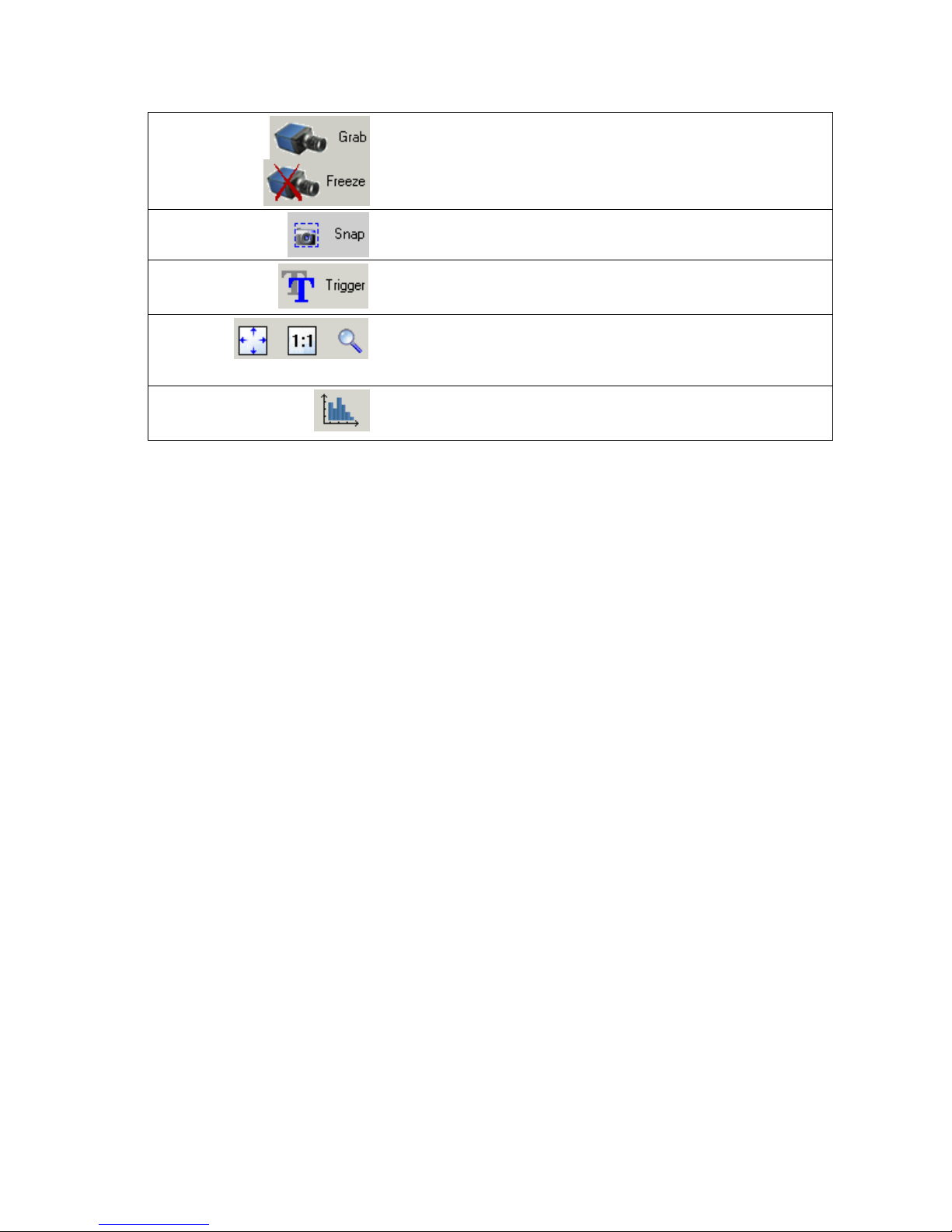
Control Buttons: The Display pane includes CamExpert control buttons. These are:
03-032-20206-00 Teledyne DALSA
Linea 2K and 4K Monochrome Line Scan Camera User's Manual 25
Acquisition control button:
Click once to start live grab, click again to stop.
Single frame grab:
Click to acquire one frame from device.
Trigger button:
With the I/ O control parameters set to Trigger Enabled, click to send a
single trigger command.
CamExpert display controls:
(these do not modify the frame buffer d ata)
Stretch image to fit, set image display to original size, or zoom the
image to virtually any size and ratio.
Histogram / Profile tool:
Select to view a histogram or line/ column profile during live
acquisition or in a still image.
Output Message pane: Displays messages from CamExpert or the device driver.
At this point you are ready to start operating the camera in order to acquire images, set camera functions,
and save settings.
Teledyne DALSA 03-032-20206-00
26 Linea 2K and 4K Monochrome Line Scan Camera User's Manual
4. Camera Operation
Factory Settings
The camera ships and powers up for the first time with the following factory settings:
Camera Link Full, 8 bit pixels
Internal trigger, line rate 10 kHz
Internal exposure control, exposure time 50 µs
1x horizontal and vertical binning
Offset 0, Gain 1x
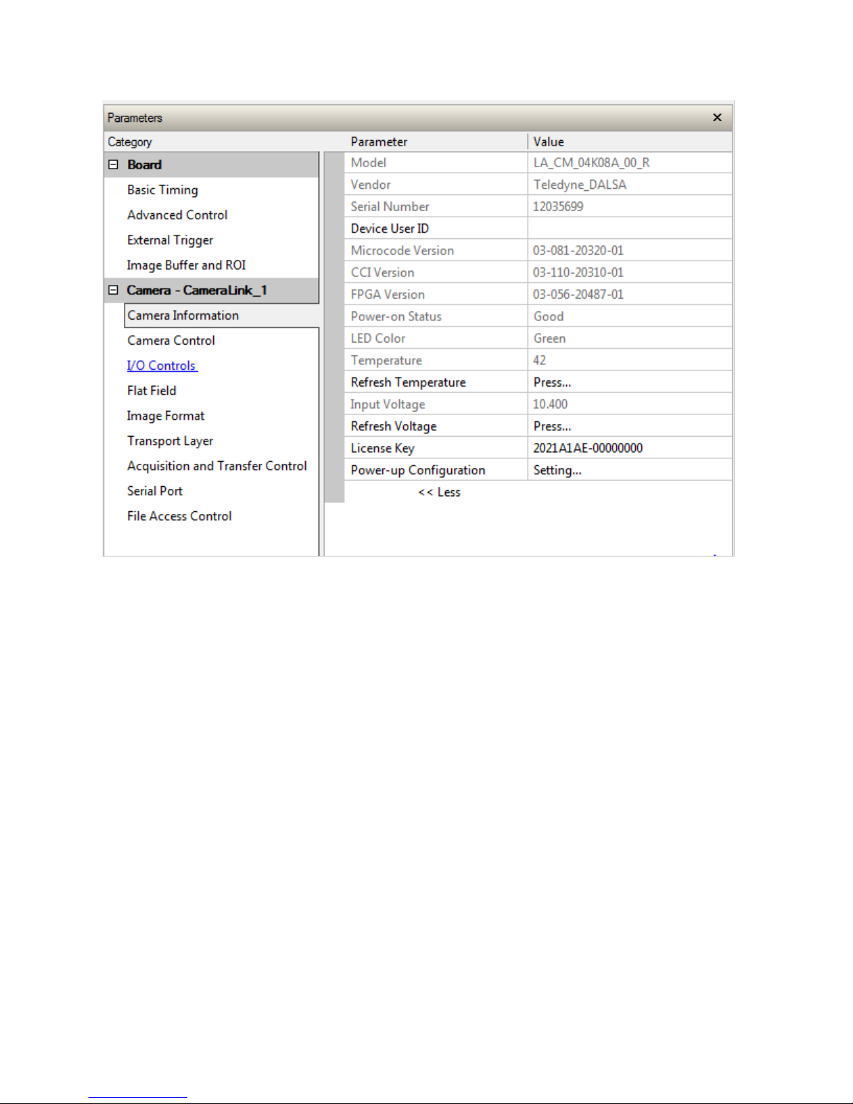
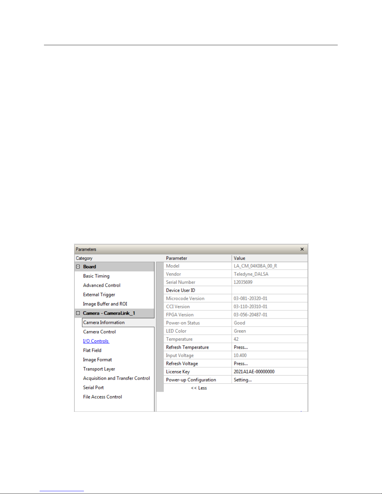
Check Camera and Sensor Information
Camera and sensor information can be retrieved via a controlling application —for example, the
CamExpert GUI shown in the following examples. Parameters such as camera model, firmware version,
sensor characteristics, etc. are read to uniquely identify the connected device.
The camera information parameters are grouped together as members of the Camera Information set.
03-032-20206-00 Teledyne DALSA
Figure 9. CamExpert’s Camera Information Window

Linea 2K and 4K Monochrome Line Scan Camera User's Manual 27
Camera Information
Parameter
Choices
User Set Default Selector
Select the camera parameters to load when the camera is reset or
powered up as the Factory set, or as User Set 1 to 8.
Selecting the set from the list automatically saves it as the default
set.
User Set Selector
Select the Factory or User set to Save or Load.
-Factory Set
-User Set 1 to 8.
User Set Load
Load the set specified by User Set Selector to the camera and m ake
it the active / current set.
User Set Save
Save the current set as selected user set.
Verify Temperature and Voltage
To determine the voltage and temperature at the camera, use the Refresh Voltage and Refresh
Temperature features found in the Camera Information set.
The temperature returned is the internal temperature in degrees Celsius. For proper operation this value
should not exceed 80 °C. If the camera exceeds the designated temperature it will stop imaging and the
LED will turn red. Once you have diagnosed and remedied the issue use the reset camera function.
Note: The voltage displayed is the cam era‘s input voltage. The voltage measurement feature of the camera
provides results within 1% of the actual voltage. The measurement can be used to set the applied voltage
to the camera.
Saving and Restoring Camera Settings
The parameters used to select, load and save user sets are grouped together under the Camera
Information set of features. There are 8 user sets available and one factory set.
Description of the Camera Settings
The camera operates in one of four settings:
1. Current operation with active settings.
2. User setting.
3. Factory setting (read-only).
4. Default setting.
The settings active during the current operation can be saved (thereby becoming the user setting) using
the User Set Save parameter. A previously saved user setting (User Set 1 to 8) or the factory settings can
be restored using the User Set Selector and User Set Load parameters.
Either the Factory or one of the User settings can be saved as the Default Setting by selecting the set in the
User Set Default Selector. The chosen set automatically saves as the default setting and is the set loaded
when the camera is reset or powered up.
Teledyne DALSA 03-032-20206-00
 Loading...