

Teledyne Compact Outdoor SSPA Operation Manual
Compact Outdoor
Solid State Power Amplifier
Operations Manual
Teledyne Paradise Datacom LLC Phone: (814) 238-3450
328 Innovation Blvd., Suite 100 Fax: (814) 238-3829
State College, PA 16803 USA Web: www.paradisedata.com
Email: sales@paradisedata.com
208495 REV F ECO 17951 07/24/2015

Teledyne Paradise Datacom LLC, a Teledyne Telecommunications company, is a single source for high power
solid state amplifiers (SSPAs), Low Noise Amplifiers (LNAs), Block Up Converters (BUCs), and Modem
products. Operating out of two primary locations, Witham, United Kingdom, and State College, PA, USA,
Teledyne Paradise Datacom has more than a 20 year history of providing innovative solutions to enable satellite
uplinks, battlefield communications, and cellular backhaul.
Teledyne Paradise Datacom LLC Teledyne Paradise Datacom Ltd.
328 Innovation Blvd., Suite 100 2-3 The Matchyns, London Road, Rivenhall End
State College, PA 16803 USA Witham, Essex CM8 3HA United Kingdom
(814) 238-3450 (switchboard) +44 (0) 1376 515636
(814) 238-3829 (fax) +44 (0) 1376 533764 (fax)
Information in this document is subject to change without notice. The latest revision of this document may be
downloaded from the company web site: http://www.paradisedata.com.
Use and Disclosure of Data
The information contained herein is classified as EAR99 under the U.S. Export Administration Regulations.
Export, re-export or diversion contrary to U.S. law is prohibited.
No part of this document may be reproduced or transmitted in any form without the written permission of
Teledyne Paradise Datacom LLC.
All rights are reserved in this document, which is property of Teledyne Paradise Datacom LLC. This document
contains proprietary information and is supplied on the express condition that it may not be disclosed,
reproduced or transmitted in any form without the written permission of Teledyne Paradise Datacom LLC.
All other company names and product names in this document are property of the respective companies.
© 2014-2015 Teledyne Paradise Datacom LLC
Printed in the USA
2 208495 REV F Operations Manual, HPA2, Compact Outdoor SSPA

Table of Contents
Table of Contents ................................................................................................................ 3
Section 1: General Information ........................................................................................ 11
1.0 Introduction ......................................................................................................... 11
1.1 Description .......................................................................................................... 11
1.2 Specifications ...................................................................................................... 11
1.3 Equipment Supplied ............................................................................................ 12
1.4 Safety Considerations ......................................................................................... 12
1.4.1 High Voltage Hazards ........................................................................... 12
1.4.2 RF Transmission Hazards .................................................................... 12
1.5 Comparisons Between Standard and Mini Compact Outdoor SSPAs ............... 13
Section 2: Installation ........................................................................................................ 15
2.0 Introduction ......................................................................................................... 15
2.1 Inspection ........................................................................................................... 15
2.2 Connector Pin-Outs ............................................................................................ 15
2.2.1 RF Input (J1) [N-type (F)] ...................................................................... 16
2.2.2 RF Output (J2) ...................................................................................... 16
2.2.3 RF Output Sample Port (J3) [N-type (F)] ............................................... 17
2.2.4 Monitor & Control Connector (J4) [MS3112E18-32S] ........................... 18
2.2.5 Link Port (J5) [MS3112E10-6S] ............................................................. 18
2.2.6 Switch Port (J6) [MS3112E10-6S] ......................................................... 18
2.2.7 Prime Power Connection (J7) [MS3102E20-3P] ................................... 18
2.2.7.1 DC Input Option [MS3102E-20-29P] ....................................... 19
2.2.8 15 VDC Output Port (J8) [MS3112E10-6S] ........................................... 19
2.2.9 Chassis Ground Terminal ...................................................................... 19
2.3 Physical Features ............................................................................................... 20
2.3.1 Summary Alarm Indicator ...................................................................... 20
2.3.2 Airflow and Removable Fan Tray .......................................................... 20
2.4 Unit Weights........................................................................................................ 21
2.5 Compact Outdoor Mounting Kit Installation ......................................................... 22
2.5.1 Safety Considerations ........................................................................... 22
2.5.2 Inspection .............................................................................................. 22
2.5.3 Installation ............................................................................................. 23
Section 3: Quick Start & Operation .................................................................................. 25
3.0 Introduction ......................................................................................................... 25
3.0.1 Remote Communications Connections ................................................. 25
3.0.2 Legacy Compact Outdoor SSPAs ......................................................... 26
3.0.3 Compact Outdoor SSPAs in Legacy Systems ....................................... 27
3.1 Port J4 Pin-Outs .................................................................................................. 28
3.1.1 Amplifier Enable (Mute/Unmute) (J4) .................................................... 30
3.1.2 Gain Adjust Input (J4) ............................................................................ 30
3.1.3 Alarms (J4) ............................................................................................ 30
3.1.3.1 Summary Alarm (J4) Form C Contacts .................................... 30
Operations Manual, HPA2, Compact Outdoor SSPA 208495 REV F 3

3.1.3.2 Auxiliary Alarm (J4) Form C Contacts ...................................... 30
3.1.3.3 Open Collector Alarm Outputs (J4) .......................................... 31
3.1.4 RF Power Detector (J4, Pin R) .............................................................. 31
3.1.5 Fan Speed Control (J4, Pin R) .............................................................. 31
3.2 Quick Start Cables .............................................................................................. 32
3.3 Quick Start Connections ..................................................................................... 33
3.3.1 Set PC Configuration ............................................................................. 33
3.3.2 Quick Start Ethernet Connection ........................................................... 33
3.3.3 Quick Start RS-232 Connection ............................................................ 34
3.3.4 Setting Custom IP Address .................................................................. 35
3.4 Universal M&C Operation ................................................................................... 36
3.4.1 Universal M&C Status Window .............................................................. 37
3.4.1.1 Signal Indicators ...................................................................... 37
3.4.1.2 Fault Status Indicators ............................................................. 38
3.4.1.3 Voltage, Current and Temperature Display ............................. 39
3.4.1.4 Gain Adjustment ...................................................................... 39
3.4.1.5 Forward and Reflected RF Power Indicators ........................... 39
3.4.2 Universal M&C Settings Window ........................................................... 40
3.4.2.1 Power Up Settings ................................................................... 40
3.4.3 IP Setup Window ................................................................................... 43
3.4.4 Universal M&C Preferences .................................................................. 44
3.5 Web-based M&C ................................................................................................. 45
3.5.1 Navigating the Web M&C ...................................................................... 46
Section 4: L Band Operation ............................................................................................. 51
4.0 Block Up Converter Overview ............................................................................. 51
4.1 ZBUC Features ................................................................................................... 52
4.2 ZBUC Converter Theory of Operation ................................................................. 53
4.3 Smart Reference Technology ............................................................................. 53
4.4 ZBUC FSK Monitor and Control .......................................................................... 54
4.5 Typical System Configuration ............................................................................. 55
4.6 IFL Cable Considerations .................................................................................... 55
Section 5: Fiber-Optic Option ........................................................................................... 57
5.0 Fiber-Optic Option Overview ............................................................................... 57
5.0.1 RCPF-1000 Fiber Optic Controller ........................................................ 57
5.0.2 External L-Band to Fiber Interface ......................................................... 58
Section 6: Performance Tests .......................................................................................... 61
6.0 Introduction ......................................................................................................... 61
6.1 Standard tests ..................................................................................................... 61
6.1.1 Swept Gain ........................................................................................... 61
6.1.2 Spurious ............................................................................................... 62
6.1.3 Input Return Loss ................................................................................. 62
6.1.4 Output Return Loss .............................................................................. 62
6.1.5 Intermodulation Distortion ..................................................................... 63
6.1.6 Power Requirements ............................................................................ 63
6.1.7 Earth Ground ........................................................................................ 64
6.1.8 Sample Port ........................................................................................ 64
4 208495 REV F Operations Manual, HPA2, Compact Outdoor SSPA

6.1.9 P
1dB
and P
........................................................................................ 64
sat
6.1.10 I/O Test .............................................................................................. 64
6.1.11 Ethernet (if equipped) ......................................................................... 64
6.2 Tests for units with integrated zBUC ................................................................... 65
6.2.1 Reference Lock ..................................................................................... 65
6.2.2 FSK ....................................................................................................... 65
6.2.3 Phase Noise .......................................................................................... 65
6.2.4 Microphonics ......................................................................................... 65
6.3 Optional Tests ..................................................................................................... 66
6.3.1 Noise Figure .......................................................................................... 66
6.3.2 Group Delay .......................................................................................... 66
6.3.3 AM/PM .................................................................................................. 66
6.3.4 Noise Power .......................................................................................... 66
6.3.5 Harmonics ............................................................................................. 66
Section 7: Maintenance & Troubleshooting .................................................................... 67
7.0 Introduction ......................................................................................................... 67
7.1 Cooling System Maintenance ............................................................................. 67
7.2 Fan Removal and Heatsink Cleaning .................................................................. 67
7.2.1 Fan Replacement .................................................................................. 68
7.3 Troubleshooting guide ........................................................................................ 68
7.3.1 Unit doesn’t power up ............................................................................ 68
7.3.2 Unit powers on, LED lamp glows red .................................................... 68
7.3.3 SSPA unit powers up, LED glows green, but no RF output .................. 68
7.3.4 Cannot connect to SSPA through remote control interface ................... 69
7.3.5 The FSK link between a modem and the SSPB unit is not working ...... 70
Section 8: Redundant System Operation ........................................................................ 71
8.0 Redundant System Concepts ............................................................................. 71
8.1 Compact Outdoor Amplifier in 1:1 Redundancy .................................................. 73
8.1.1 Hardware Setup .................................................................................... 74
8.1.2 Software Setup ...................................................................................... 75
8.1.2.1 Stand-Alone 1:1 Redundant System ....................................... 75
8.1.2.2 PC Control using RS232 and Paradise M&C Software .......... 78
8.1.2.3 PC Control using RS-485 and Paradise M&C Software ......... 83
8.2 1:2 Redundant Systems ...................................................................................... 85
8.3 1:2 Redundant Systems with L-Band Input ......................................................... 88
Section 9: Fixed Phase Combined Redundant Systems ................................................ 93
9.0 Phase Combining Overview ................................................................................ 93
9.1 1:1 Fixed Phase Combined System Components ............................................... 95
9.1.1 Signal Box Assembly ............................................................................. 95
9.2 1:1 Fixed Phase Combined System Operation with the FPRC-1100 .................. 97
9.3 1:1 Fixed Phase Combined System with L-Band Input ....................................... 98
9.3.1 1:1 Fixed Phase Combined System with L-Band Input Components .... 99
9.3.2 Signal Box Assembly ............................................................................. 99
9.3.3 Redundant BUC Operation ................................................................... 99
9.3.4 Adjusting the Phase Combining ........................................................... 99
9.4 1:2 Fixed Phase Combined Systems ................................................................ 101
Operations Manual, HPA2, Compact Outdoor SSPA 208495 REV F 5

9.4.1 1:2 Fixed Phase Combined System Components ............................... 102
9.4.2 Signal Box Assembly ........................................................................... 102
9.5 1:2 Fixed Phase Combined System Operation with FPRC-1200 ...................... 104
9.5.1 Phase Adjustment ............................................................................... 105
Section 10: Remote Control Interface ............................................................................ 107
10.0 Serial Protocol Overview ................................................................................. 107
10.1 Serial communication ...................................................................................... 110
10.1.1 Header Packet ................................................................................... 110
10.1.1.1 Frame Sync Word ................................................................ 110
10.1.1.2 Destination Address ............................................................. 110
10.1.1.3 Source Address ................................................................... 111
10.1.2 Data Packet ....................................................................................... 111
10.1.2.1 Protocol ID ........................................................................... 111
10.1.2.2 Request ID ........................................................................... 111
10.1.2.3 Command ............................................................................ 111
10.1.2.4 Data Tag .............................................................................. 112
10.1.2.5 Data Address / Error Status / Local Port Frame Length ....... 113
10.1.2.6 Data Length ......................................................................... 113
10.1.2.7 Data Field ............................................................................ 113
10.1.3 Trailer Packet .................................................................................... 114
10.1.3.1 Frame Check ....................................................................... 114
10.1.4 Timing issues .................................................................................... 114
10.1.5 Serial Communications Protocol ....................................................... 115
10.1.6 Serial Communication Examples ....................................................... 119
10.2 Ethernet Interface ............................................................................................ 124
10.2.1 Overview ........................................................................................... 124
10.2.2 IPNet Interface .................................................................................. 124
10.2.2.1 General Concept .................................................................. 124
10.2.2.2 Setting IPNet Interface ......................................................... 126
10.2.2.3 Troubleshooting IP connectivity ........................................... 126
10.2.4 SNMP interface ................................................................................. 127
10.2.4.1 SNMP MIB Tree ................................................................... 128
10.2.4.2 Description of MIB Entities ................................................... 129
10.2.5 Extended SNMP for GaN Compact Outdoor SSPAs ......................... 130
10.2.5.1 Extended SNMP MIB Tree .................................................. 131
10.2.5.2 Extended SNMP MIB Tree Elements in Detail ..................... 133
10.3 M&C via SNMP ............................................................................................... 137
10.3.1 Connecting to a MIB browser ............................................................ 138
10.3.2 SNMP V3 Implementation Issues ...................................................... 139
Section 11: Option, Universal Handheld Controller ...................................................... 141
11.0 Overview, Universal Handheld Controller ....................................................... 141
Appendix A: Quick Start Cable ....................................................................................... 143
Appendix B: Alternate System Configurations ............................................................. 145
Appendix C: Maintenance Switch Mode ........................................................................ 147
Appendix D: Documentation ........................................................................................... 149
6 208495 REV F Operations Manual, HPA2, Compact Outdoor SSPA

List of Figures
Figure 2-1: Outline, Compact Outdoor Solid State Amplifier ................................................ 15
Figure 2-2: Input Side, Compact Outdoor Amplifier ............................................................. 16
Figure 2-3: RF Output Side of C-Band Compact Outdoor SSPA ......................................... 17
Figure 2-4: Bottom View, Compact Outdoor Amplifier ........................................................ 17
Figure 2-5: Improper Mounting ............................................................................................ 20
Figure 2-6: Bolt Mounting Bracket to Unit ............................................................................ 23
Figure 2-7: Unit Ready for Boom Installation ....................................................................... 23
Figure 2-8: CO Mount Completed ........................................................................................ 24
Figure 3-1: J4 Connections for Ethernet Communications .................................................. 25
Figure 3-2: J4 Connections for RS-485 Comms .................................................................. 26
Figure 3-3: J4 Connections for RS-232 Comms .................................................................. 26
Figure 3-4: J4 Connections for RS-485 Comms for S/N <300,000 ..................................... 26
Figure 3-5: J4 Connections for RS-232 Comms for S/N <300,000 ..................................... 27
Figure 3-6: J4 Connections for RS-485 Comms for S/N >300,000 in Legacy ..................... 27
Figure 3-7: Ethernet Quick Start Cable, 207755 .................................................................. 32
Figure 3-8: RS-232 Quick Start Cable, 207998 ................................................................... 32
Figure 3-9: Universal M&C Add Unit menu .......................................................................... 36
Figure 3-10: Add Compact Outdoor SSPA window, via Serial or Internet ........................... 36
Figure 3-11: Universal M&C Status Window ........................................................................ 37
Figure 3-12: Fault Indicators ................................................................................................ 38
Figure 3-13: Universal M&C, Settings ................................................................................. 40
Figure 3-14: Spare Fault Wizard .......................................................................................... 42
Figure 3-15: Universal M&C, IP Setup ................................................................................. 43
Figure 3-16: Preferences Window ....................................................................................... 44
Figure 3-17: Example, Log entry ......................................................................................... 44
Figure 3-18: Enter IP address for Compact Outdoor SSPA ................................................. 45
Figure 3-19: M&C Applet loading into browser window ...................................................... 45
Figure 3-20: Enter password (default is “paradise”) ............................................................. 46
Figure 3-21: Status and Faults window descriptions ........................................................... 46
Figure 3-22: Communication Settings window descriptions ................................................. 47
Figure 3-23: General Settings window descriptions ............................................................. 48
Figure 3-24: Fault Settings window descriptions ................................................................. 49
Figure 4-1: Configuration Matrix, Compact Outdoor SSPA, BUC Options ........................... 51
Figure 4-2: Compact Outdoor Block Diagram of BUC / SSPA System ................................ 52
Figure 4-3: Compact Outdoor SSPB with PD25 Evolution Modem ...................................... 55
Figure 5-1: RCPF-1000 front, rear panels ........................................................................... 57
Figure 5-2: Outline Drawing, External L-Band to fiber interface ........................................... 58
Figure 5-3: Block Diagram, Compact Outdoor with external fiber transceiver ..................... 59
Figure 5-4: System example, SSPA with External Fiber to L-Band Converter ..................... 59
Figure 6-1: Spurious and Gain Data .................................................................................... 61
Figure 6-2: Return Loss, Intermodulation and Phase Noise Data ........................................ 62
Figure 6-3: M&C, Output Power, Ground, Phase Lock and Misc. Data ............................... 63
Figure 7-1: Fan Removal from Amplifier Assembly ............................................................. 67
Figure 8-1: 1:1 System with input (coaxial) switch and output (waveguide) switch .............. 71
Figure 8-2: 1:1 Redundant System with input splitter substituted for input switch ............... 71
Figure 8-3: 1:1 Redundant System with L Band input ......................................................... 72
Figure 8-4: Typical 1:1 Redundant System Outline ............................................................. 73
Operations Manual, HPA2, Compact Outdoor SSPA 208495 REV F 7

Figure 8-5: 1:1 Redundant System with Link Cable and Switch Cable installed .................. 74
Figure 8-6: 1:1 System with RS-232 Communication to each Amplifier ............................... 75
Figure 8-7: M&C Program “SSPA Settings” window ............................................................ 76
Figure 8-8: Adding a SSPA Monitor and Control Window .................................................... 78
Figure 8-9: Add New Compact Outdoor SSPA window ....................................................... 79
Figure 8-10: Individual SSPA Operation Window ................................................................ 79
Figure 8-11: Universal M&C, Add Unit Menu Tree ............................................................... 80
Figure 8-12: Universal M&C, Add 1:1 Redundant System Window ..................................... 80
Figure 8-13: Universal M&C, showing a configured 1:1 Redundant System ....................... 81
Figure 8-14: Dialog window, Affirm mute of on-line amplifier ............................................... 81
Figure 8-15: Control Panel showing Unit 1 faulted and signal routed to Unit 2 .................... 82
Figure 8-16: Unit 1 Status panel showing Summary and Temperature Faults ..................... 82
Figure 8-17: 1:1 Redundant System with RS-485 Full Duplex Communication ................... 83
Figure 8-18: 1:1 Redundant System with RS-485 Half Duplex Communication .................. 84
Figure 8-19: 1:2 Redundant System .................................................................................... 85
Figure 8-20: 1:2 Redundant System Block Diagram ............................................................ 85
Figure 8-21: Outline, 1:2 Redundant System ....................................................................... 86
Figure 8-22: Schematic, 1:2 Redundant System ................................................................. 87
Figure 8-23: 1:2 System with L Band Input and Internally Referenced BUCs ...................... 88
Figure 8-24: 1:2 System, External Reference, no reference to stand-by BUC ..................... 89
Figure 8-25: 1:2 System with (3) 10MHz inputs through the input switches ........................ 90
Figure 8-26: 1:2 System, External Reference Combiner Assembly ..................................... 91
Figure 9-1: Phase Combined Amplifier System ................................................................... 93
Figure 9-2: 1:1 Fixed Phase Combined System with FPRC-1100 controller ....................... 94
Figure 9-3: Outline, 1:1 Fixed Phase Combined System ..................................................... 96
Figure 9-4: FPRC-1100 Phase Combined System Controller .............................................. 97
Figure 9-5: 1:1 Phase Combined System with HPA control of BUC redundancy................. 98
Figure 9-6: Connect to coupler ............................................................................................ 99
Figure 9-7: Outline, 1:1 Fixed Phase Combined System with L-Band Input ...................... 100
Figure 9-8: Phase adjuster ................................................................................................ 101
Figure 9-9: Block Diagram, 1:2 Fixed Phase Combined System ....................................... 101
Figure 9-10: Outline, 1:2 Fixed Phase Combined System, C-Band ................................... 103
Figure 9-11: FPRC-1200 1:2 Phase Combined Redundant Controller .............................. 104
Figure 9-12: HPA #1 & HPA #3 on line with HPA #2 on standby ....................................... 104
Figure 9-13: Connect to coupler ........................................................................................ 105
Figure 10-1: Compact Outdoor remote control interface stack .......................................... 107
Figure 10-2: Basic Communication Packet ........................................................................ 110
Figure 10-3: Header Sub-Packet ....................................................................................... 110
Figure 10-4: Data Sub-Packet ........................................................................................... 111
Figure 10-5: Trailer Sub-Packet ......................................................................................... 114
Figure 10-6: UDP Redirect Frame Example ...................................................................... 125
Figure 10-7: Universal M&C, IP Setup tab ......................................................................... 137
Figure 10-8: Universal M&C, Settings tab .......................................................................... 137
Figure 10-9: GetIF Application Parameters Tab ................................................................ 138
Figure 10-10: Getif MBrowser window, with update data in output data box ..................... 138
Figure 11-1: Universal Handheld Controller (RCH-1000) .................................................. 141
Figure 11-2: Quick Start Cable (L212638-2) for Compact Outdoor SSPAs ....................... 141
Figure A-1: Ethernet Quick Start Cable ............................................................................. 143
Figure A-2: RS-232 Quick Start Cable, 207998 ................................................................. 144
8 208495 REV F Operations Manual, HPA2, Compact Outdoor SSPA

Figure B-1: Mixed Redundant System using New and Original CO Amplifiers .................. 145
Figure B-2: Redundant System using RCP2-1100 Controller ............................................ 146
List of Tables
Table 2-1: Link Port (J5) Pin-Outs ....................................................................................... 18
Table 2-2 Switch Port (J6) Pin-Outs .................................................................................... 18
Table 2-3: AC Line Input Connector .................................................................................... 18
Table 2-4: DC Input Connector, MS3102E-20-29P ............................................................. 19
Table 2-5: +15 VDC Output Port (J8) Pin-Outs ................................................................... 19
Table 2-6: Compact Outdoor SSPA Weights ....................................................................... 21
Table 2-7: Mounting Kit Parts List ........................................................................................ 22
Table 3-1: Monitor & Control Connector (J4) Pin-Out (Ethernet capable)............................ 28
Table 3-2: Monitor & Control Connector (J4) Pin-Out (Non-Ethernet) ................................. 29
Table 4-1: ZBUC Converter Frequency Specifications ........................................................ 52
Table 4-2: ZBUC RF Output Phase Noise Specification ...................................................... 53
Table 4-3: Common Coaxial Cable Characteristics ............................................................ 55
Table 8-1: Returning Amp 2 to Stand-by Mode After Fault on Thread 1 or 3 ....................... 91
Table 10-1: Interface Selection (Serial Numbers < 400,000) ............................................. 108
Table 10-2: Interface Selection (Serial Numbers > 399,999) ............................................. 108
Table 10-3: Unique Network Address Hardware Select .................................................... 109
Table 10-4: Command Byte Values ................................................................................... 112
Table 10-5: Data Tag Byte Values ..................................................................................... 112
Table 10-6: Error Status Bytes .......................................................................................... 113
Table 10-7: Request Frame Structure ............................................................................... 115
Table 10-8: Response Frame Structure ............................................................................ 115
Table 10-9: System Settings Data Values ......................................................................... 116
Table 10-10: System Threshold Data Values .................................................................... 117
Table 10-11: System Condition Addressing ....................................................................... 118
Table 10-12: OSI Model for Compact Outdoor SSPA Ethernet IP Interface ...................... 125
Table 10-13: Detailed Settings for CO SSPA mode (Device Type=2) ............................... 134
Table 10-14: Detailed Thresholds ...................................................................................... 136
Table 10-15: Detailed Conditions ...................................................................................... 136
Table A-1: Wiring Chart, Ethernet Quick Start Cable ......................................................... 143
Table A-2: Wiring Chart, RS-232 Quick Start Cable .......................................................... 144
Table C-1: Switch Port (J6) Pin-Outs ................................................................................. 147
Table C-2: Link Port (J5) Pin-Outs ..................................................................................... 147
Operations Manual, HPA2, Compact Outdoor SSPA 208495 REV F 9

THIS PAGE INTENTIONALLY LEFT BLANK
10 208495 REV F Operations Manual, HPA2, Compact Outdoor SSPA

Section 1: General Information
1.0 Introduction
This section provides the general information for the Teledyne Paradise Datacom LLC line of
Compact Outdoor Solid State Power Amplifiers. The Compact Outdoor SSPA has been
designed and manufactured to be an extremely robust and reliable amplifier. It is well suited
for harsh outdoor environments.
1.1 Description
The Compact Outdoor SSPA is a one-piece integrated Satcom amplifier system. It includes
the AC/DC power supply, microwave amplifier module, microprocessor based monitor and
control circuitry, and an efficient thermal management system.
The Compact Outdoor SSPA is very well suited for environmentally demanding conditions
where reliability is paramount. At the heart of the amplifier system is a multifunction solid state
power amplifier (SSPA) module. It has a full compliment of parallel I/O monitor and control
signals as well as serial I/O capability using a PC and host communication software from
Teledyne Paradise Datacom LLC.
Proprietary thermal management techniques allow even the highest output power level amplifiers to operate reliably in environments up to 60°C ambient temperature and 100% relative
humidity.
The reduced size and weight of this amplifier system allow it to be used in a wide variety of
installations; many of which historically precluded the use of Solid State power amplifiers.
This amplifier is ideal for mounting on the boom of small antennas or anywhere that size and
weight are a major concern.
Features include:
• Compact Size: 10.0 in x 19.5 in x 6.50 in. (254 mm x 495 mm x 165 mm)
• Very light weight: Base units weigh as little as 36 lb. (16.4 kg)
• Auto-Sensing Power Factor Corrected Power Supply
• RF Gain Adjustment: 55 dB to 75 dB minimum with 0.1 dB resolution
• Output Power Detection
• Output Power Sample Port
• Internal 1:1 Redundant Capability
• Optional L-Band Input Capability
• Serial (RS-232 / RS-485), Ethernet or Parallel Monitor & Control Circuitry
• Windows Monitor & Control Software
1.2 Specifications
Refer to Appendix D for full specifications of the Compact Outdoor SSPA.
Operations Manual, HPA2, Compact Outdoor SSPA 208495 REV F 11
1.3 Equipment Supplied
The following equipment is supplied with each unit:
• The Compact Outdoor Amplifier Assembly;
• Prime power mating connector: AC - MS3106E20-3S; DC - MS3106F20-29S
• Quick Start Serial (Ethernet) Communication Cable, L207755-2, -OR-
Quick Start Serial (RS-232 / RS-485) Communication Cable, L207998-2
• Product Guide CD with SSPA Monitor & Control Software
• Operations Manual, HPA2, Compact Outdoor SSPA (208495; this manual)
• M&C (J4) Mating Connector, MS3116F18-32P
• Waveguide gaskets (dependent on frequency band)
• Sealing tape (87F730)
1.4 Safety Considerations
Potential safety hazards exist unless proper precautions are observed when working with this
unit. To ensure safe operation, the user must follow the information, cautions, and warnings
provided in this manual as well as the warning labels placed on the unit itself.
1.4.1 High Voltage Hazards
Only qualified service personnel should service the internal electronic
circuitry of the Compact Outdoor Amplifier. High DC voltages (300 VDC) are
present in the power supply section of the amplifier. Care must be taken
when working with devices that operate at this high voltage levels. It is
recommended to never work on the unit or supply prime AC power to the unit while the cover
is removed.
1.4.2 RF Transmission Hazards
RF transmissions at high power levels may cause eyesight damage and skin
burns. Prolonged exposure to high levels of RF energy has been linked to a
variety of health issues. Please use the following precautions with high levels
of RF power.
• Always terminate the RF input and output connector prior to applying prime AC
input power.
• Never look directly into the RF output waveguide
• Maintain a suitable distance from the source of the transmission such that the power
density is below recommended guidelines in ANSI/IEEE C95.1. The power density
specified in ANSI/IEEE C95.1-1992 is 10 mW/cm
OSHA Standard 1910.97.
• When a safe distance is not practical, RF shielding should be used to achieve the
recommended power density levels.
2
. These requirements adhere to
12 208495 REV F Operations Manual, HPA2, Compact Outdoor SSPA

1.5 Comparisons Between Standard and Mini Compact Outdoor SSPAs
In 2010, Teledyne Paradise Datacom introduced a smaller outdoor SSPA package based on
the standard Compact Outdoor SSPA described in this manual.
While similar in function, there are some differences that prevent immediate substitution of a
Standard Compact Outdoor unit type with a Mini Compact Outdoor unit in a system. Some of
the differences between the Standard and Mini Compact Outdoor amplifiers are outlined
below:
• AC Mains connector
• Slight variation in protocol
• No analog gain control on J4 in Mini Compact Outdoor SSPA
• No RF Power Detector analog output on J4 in Mini Compact Outdoor SSPA
• No Low RF Fault output on J4 in Mini Compact Outdoor SSPA
• No BUC Alarm output on J4 in Mini Compact Outdoor SSPA
• No Spare Input on J4 in Mini Compact Outdoor SSPA
Due to the size differences between the standard Compact Outdoor SSPA and the Mini
Compact Outdoor SSPA, the following form factors also differ:
• Mounting kit configuration
• Waveguide center line measurements
• Location of connectors
Operations Manual, HPA2, Compact Outdoor SSPA 208495 REV F 13

THIS PAGE INTENTIONALLY LEFT BLANK
14 208495 REV F Operations Manual, HPA2, Compact Outdoor SSPA
Section 2: Installation
2.0 Introduction
This section provides information for the initial inspection, installation, external connections,
and shipment of the Compact Outdoor SSPA unit.
2.1 Inspection
When the unit is received, an initial inspection should be completed. Ensure that the shipping
container is not damaged. If it is, have a representative from the shipping company present
when the container is opened. Perform a visual inspection of the Compact Outdoor Amplifier
to make sure that all items on the packing list are enclosed. If any damage has occurred or if
items are missing, contact:
Teledyne Paradise Datacom LLC
328 Innovation Park, Suite 100
State College, PA 16803
Phone: 1 (814) 238-3450
Fax: 1 (814) 238-3829
2.2 Connector Pin-Outs
The following section details the connector pin-outs for the Mini Compact Outdoor SSPA.
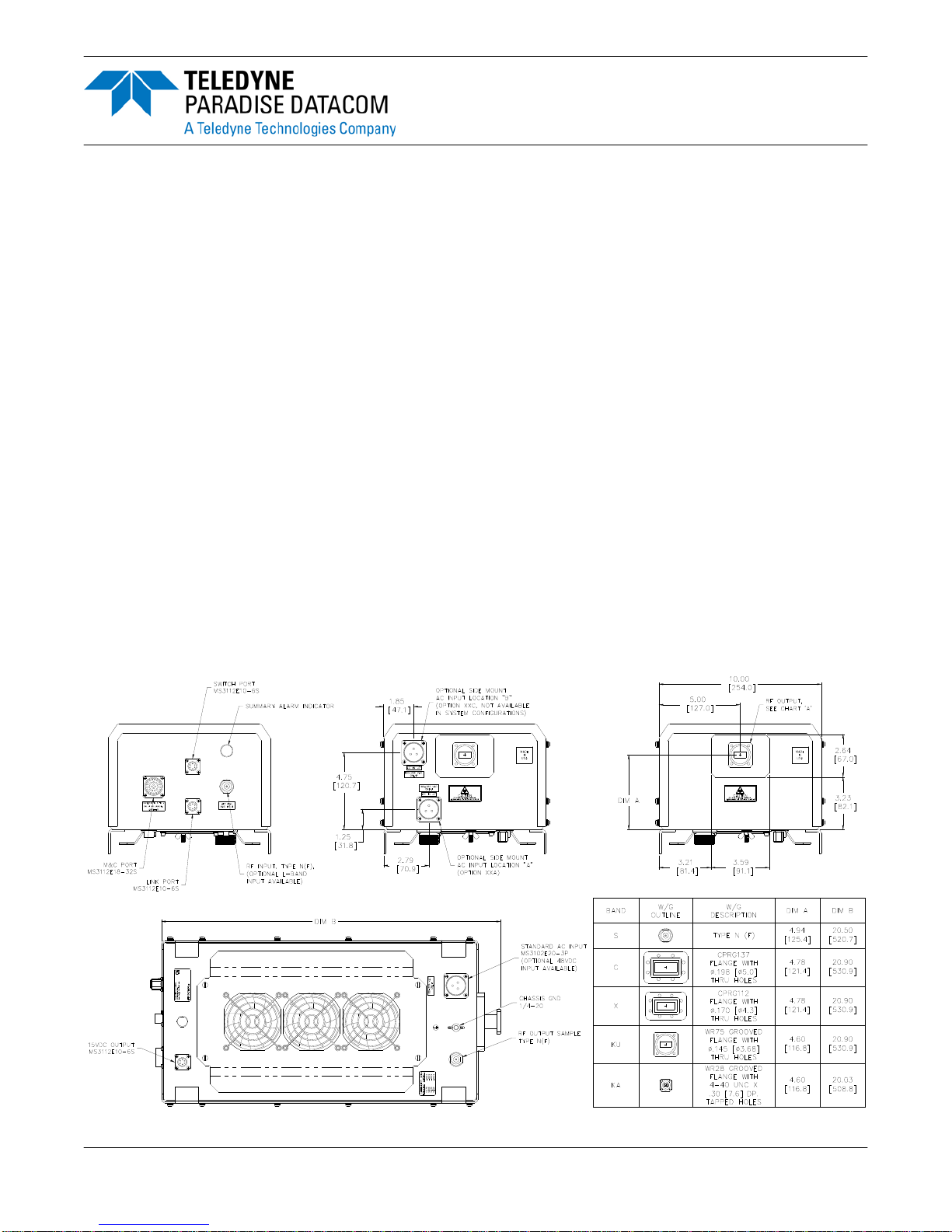
Figure 2-1 shows the overall dimensioned outline of a Compact Outdoor Amplifier. The
connector locations can be found in Figures 2-2 through 2-4.
SSPA
STATUS
SWITCH
J6
M & C
J4
J8
AUX POWER
RF IN
J1
LINK
J5
P/N: LXXXXXX-X
MODEL: XXXXXXXXXXXX
S/N: XXXX
J7
AC IN
J3
SAMPLE
RF OUT
J2
RF OUT
J2
Figure 2-1: Outline, Compact Outdoor Solid State Amplifier
Operations Manual, HPA2, Compact Outdoor SSPA 208495 REV F 15
2.2.1 RF Input (J1) [N-type (F)]
The RF Input connector is a type N female connector. The Compact Outdoor SSPA has a
default maximum nominal gain of 75 dB minimum. Therefore the maximum input signal
required to saturate the amplifier can be calculated as:
Input Power = P
- 75 dB
sat
For example, if a 50 W Ku-Band Compact Outdoor amplifier is used in a system it has a P
sat
=
47.0 dBm. Therefore the maximum input power should be limited to -28 dBm. Slightly higher
input power levels will not damage the amplifier but will result in higher levels of distortion in
the output signal.
WARNING! The maximum input level should be limited to +15 dBm to
avoid damaging the amplifier.
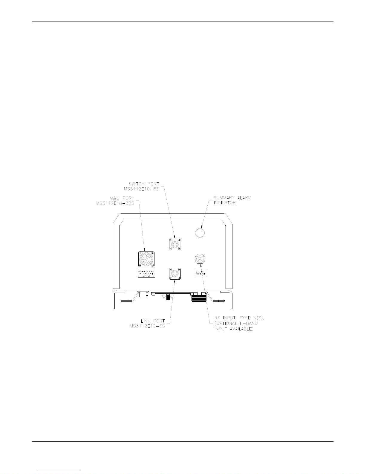
Figure 2-2 shows the input side of the Compact Outdoor Amplifier. This side contains the RF
input (J1), M&C input (J4), and the Interface connections (J5, J6).
SSPA
STATUS
SWITCH
J6
M & C
J4
LINK
J5
RF IN
J1
Figure 2-2: Input Side, Compact Outdoor Amplifier
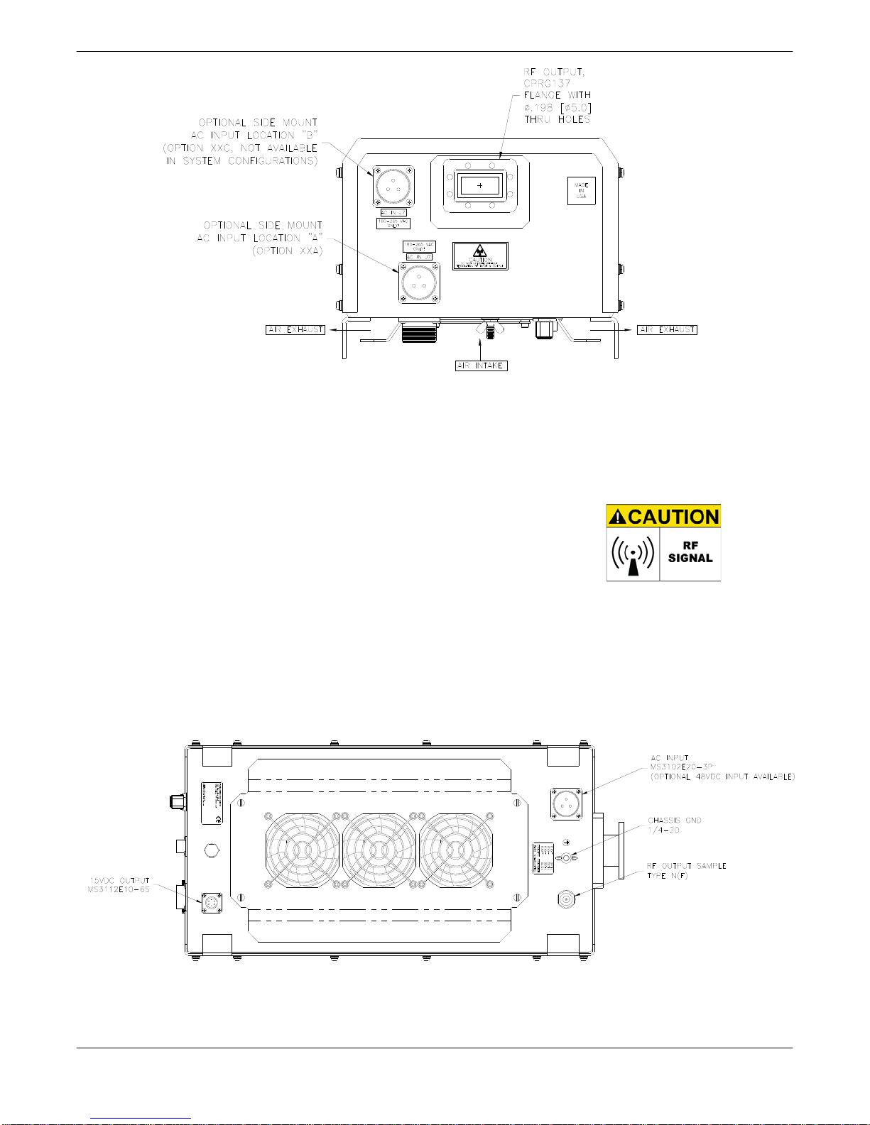
2.2.2 RF Output (J2)
The RF Output is brought out through waveguide in the Compact Outdoor Amplifier. Figure
2-3 shows the output of a C-Band Compact Outdoor Amplifier. The Ku-Band amplifiers have a
WR75 grooved flange, while the C-Band and X-Band amplifiers have CPR style grooved
flanges (CPRG-137 for C-Band; CPRG-112 for X-Band). Ka-Band amplifiers utilize a WR28
grooved flange. S-Band units are fitted with Type N (F) connectors at the RF Output.
16 208495 REV F Operations Manual, HPA2, Compact Outdoor SSPA
RF OUT
J2
Figure 2-3: RF Output Side of C-Band Compact Outdoor SSPA
Caution should be observed here to ensure that the antenna or a suitable termination is
connected to this port before operating the amplifier. The amplifier is protected against full
reflection but dangerous levels of microwave energy can be present at this port.
WARNING! Radiation hazard when un-terminated. Do
not operate the SSPA without terminating the RF Output
(J2). Do not look directly into the RF Output waveguide.
2.2.3 RF Output Sample Port (J3) [N-type (F)]
The RF Output Sample port, J3, is located on the bottom of the amplifier as shown in Figure
2-4. This connector provides a -40 dBc sample of the amplifier’s output signal. It is a N-type
female connector.
MODEL: XXXXXXXXXXXX
S/N: XXXX
J7
P/N: LXXXXXX-X
J8
AUX POWER
AC IN
J3
SAMPLE
Figure 2-4: Bottom View, Compact Outdoor Amplifier
Operations Manual, HPA2, Compact Outdoor SSPA 208495 REV F 17
2.2.4 Monitor & Control Connector (J4) [MS3112E18-32S]
The M&C, Monitor and Control, connector is the primary input for controlling the amplifier and
monitoring fault conditions. It is a 32-pin circular connector, MS3112E18-32S. It requires a
mating connector, MS3116F18-32P, which is supplied with the unit. The pin-out for this
connector is described in Tables 3-1 and 3-2.
2.2.5 Link Port (J5) [MS3112E10-6S]
The interface connector is used to connect between two Compact Outdoor Amplifiers when
used in a 1:1 redundant system. It is a 6 pin circular connector, MS3112E10-6S. It requires a
mating connector, MS3116F10-6P. A link cable is provided with a 1:1 Redundancy Kit which
can be purchased separately. See Table 2-1.
Table 2-1: Link Port (J5) Pin-Outs
Pin # on J5 Connection Pin # on J5 Connection
A LINK OUT D N/C
B LINK IN E N/C
C N/C F GND
2.2.6 Switch Port (J6) [MS3112E10-6S]
When used in a 1:1 redundant system, the waveguide switch must be connected to the switch
port of each amplifier (MS3112E10-6S). See Table 2-2. It mates with MS3116F10-6P.
Table 2-2 Switch Port (J6) Pin-Outs
Pin # on J6 Connection Pin # on J6 Connection
A N/C D N/C
B N/C E POS 2
C +28 VDC F POS 1
2.2.7 Prime Power Connection (J7) [MS3102E20-3P]
The AC Input connector, J7, is located on the bottom side of the Compact Outdoor Amplifier
package (see Figure 2-4). There are also two alternate placements for this connector on the
RF Output end of the amplifier as shown in Figure 2-3. This connector is a 3-pin circular
connector, MS3102E20-3P. The mating connector (MS3106E20-3S) is shipped with the unit.
The pin out for this connector is given in Table 2-3.
Table 2-3: AC Line Input Connector
Pin # on J7 Connection
A L1
B GND
C L2/N
WARNING! Always terminate the RF input and output connectors prior to
applying prime AC input power!
18 208495 REV F Operations Manual, HPA2, Compact Outdoor SSPA
The power supplies provide universal AC input by using auto-sensing power supplies. The
AC input can operate over a range of 90-265 VAC, at 47 to 63 Hz. The power supply is also
power factor corrected, enabling the unit to achieve a power factor greater than 0.93.
Refer to the specification sheet in Appendix D for information regarding prime power vs. RF
output power. The specification sheet shows whether your unit operates at 90-265 VAC or
180-265 VAC. An option for 110 VAC prime power is available for the higher-powered units.
2.2.7.1 DC Input Option [MS3102E-20-29P]
The Compact Outdoor Amplifier can also be configured with a DC Input Voltage power
supply. The DC Input Voltage can range from 42-60 VDC. When using a DC input voltage the
input power connector, J7, is configured per Table 2-4. The mating connector (MS3106F20-
29S) is supplied with the unit.
Table 2-4: DC Input Connector, MS3102E-20-29P
Pin # on J7 Connection
B +48 V
C +48 V
D +48 V
K -48 V
Pin # on J7
L
M
N
Connection
-48 V
-48 V
GND
2.2.8 15 VDC Output Port (J8) [MS3112E10-6S]
The 15 VDC Output, J8, is located on the bottom side of the amplifier as shown in Figure 2-3.
This provides +15 VDC and up to 1 Amp current to any external equipment. It is a 6-pin
MS-type connector (see Table 2-5 for pin-outs) and mates with MS3116F10-6P.
Table 2-5: +15 VDC Output Port (J8) Pin-Outs
Pin # on J8 Connection Pin # on J8 Connection
A EXTERNAL FAULT IN D GND
B FAULT PULLUP E +15V EXTERNAL
C +15V LNA F GND
2.2.9 Chassis Ground Terminal
A Chassis ground terminal is provided on the bottom side of the amplifier. A ¼ - 20 threaded
terminal is provided for equipment grounding.
Operations Manual, HPA2, Compact Outdoor SSPA 208495 REV F 19
2.3 Physical Features
In addition to the I/O connectors, the Compact Outdoor user-friendly features include a summary alarm indicator and removable fan tray.
2.3.1 Summary Alarm Indicator
A summary alarm indicator LED is located on the input side of the amplifier. When the SSPA
is online, this indicator illuminates GREEN. When the unit experiences a fault condition, the
indicator illuminates RED.
2.3.2 Airflow and Removable Fan Tray
The Compact Outdoor Amplifier’s cooling system represents a landmark in microwave telecommunication amplifiers. It features a unique system of heatsinks that have been computer
optimized to provide extremely efficient cooling of all of the system’s functional blocks. This
high efficiency cooling system is primarily responsible for the small overall package size and
reduced weight of the unit (approximately 36 lbs or 16.4 kg).
The cooling system is based on a forced convection technique in which the system fans provide the air intake while the exhaust is brought out around the outer perimeter of the fans.
The air intake and exhaust are both located on the bottom side of the amplifier. The intake is
brought through three fans while the exhaust is along the two rows of heatsink fins as seen in
Figure 2-3.
A minimum clearance of 6 inches (152 mm) should be maintained between the bottom of the
amplifier and any mounting surface. This will ensure that there is no forced re-circulation of
airflow from exhaust to intake.
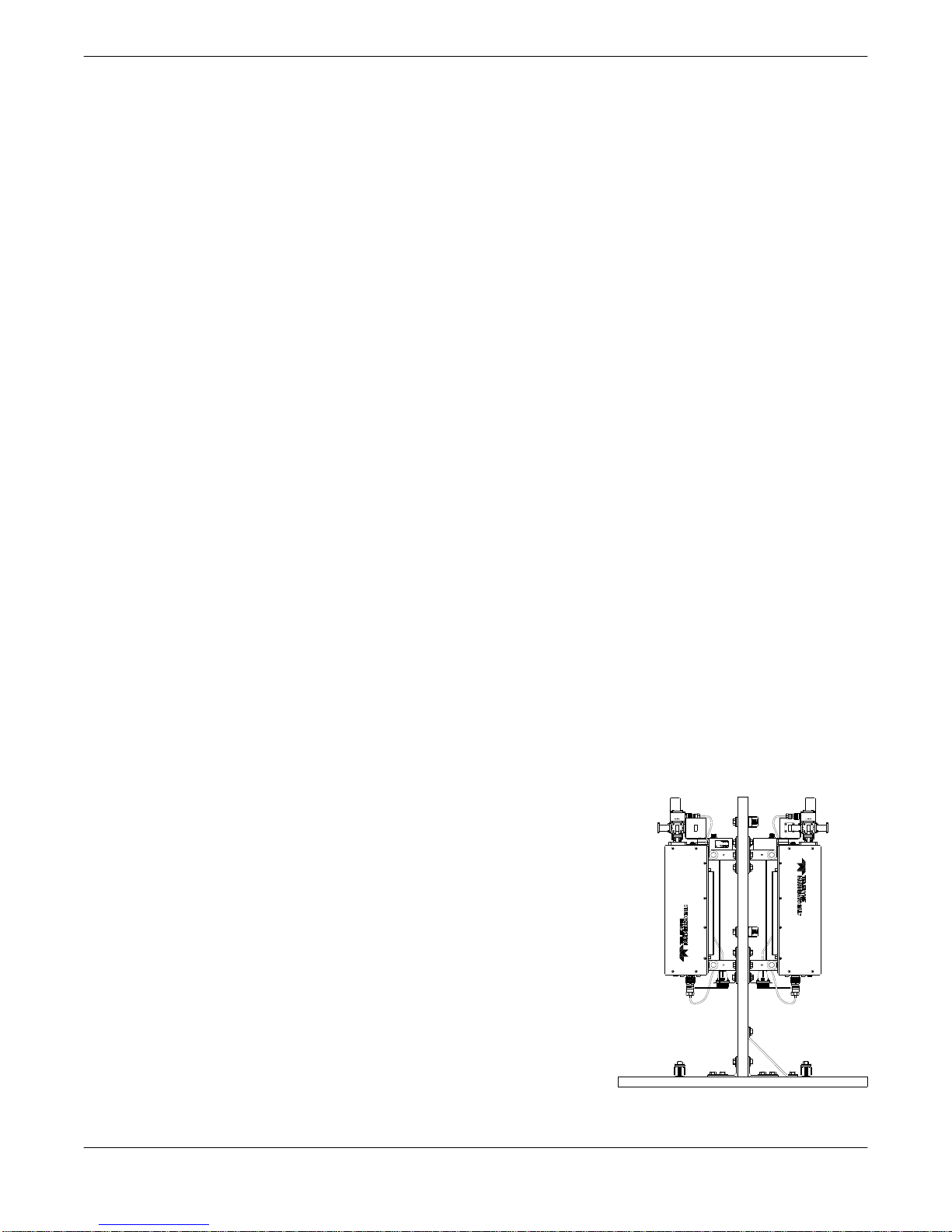
WARNING! The Compact Outdoor SSPA should NEVER be mounted with
the fans facing up!
The fans should be examined periodically and any obstruction or debris should be cleared.
Inadequate air flow can cause the amplifier to overheat and
cause a temperature fault. See Section 7 for instructions on
how to clean the fan assembly and heatsink.
In system configurations, ensure that each unit in the system
has sufficient ambient airflow, and adequate space to maintain
the fans for each unit. Figure 2-5 shows an improper method
for mounting a Compact Outdoor SSPA system. Not only do
the fans oppose each other, thereby potentially causing thermal issues, but the configuration leaves insufficient space to
remove the fans to periodically clean the heatsink.
The fans provide a maximum air flow of 103 CFM each
(maximum air pressure of 0.691 inches H2O at zero air flow)
and produce 54.0 dB-A measured at a distance of 1 meter
from the fan intake.
Figure 2-5: Improper
P/N: LXXXXXX-X
S/N: XXXX
MODEL: XXXXXXXXXXXX
mounting
20 208495 REV F Operations Manual, HPA2, Compact Outdoor SSPA
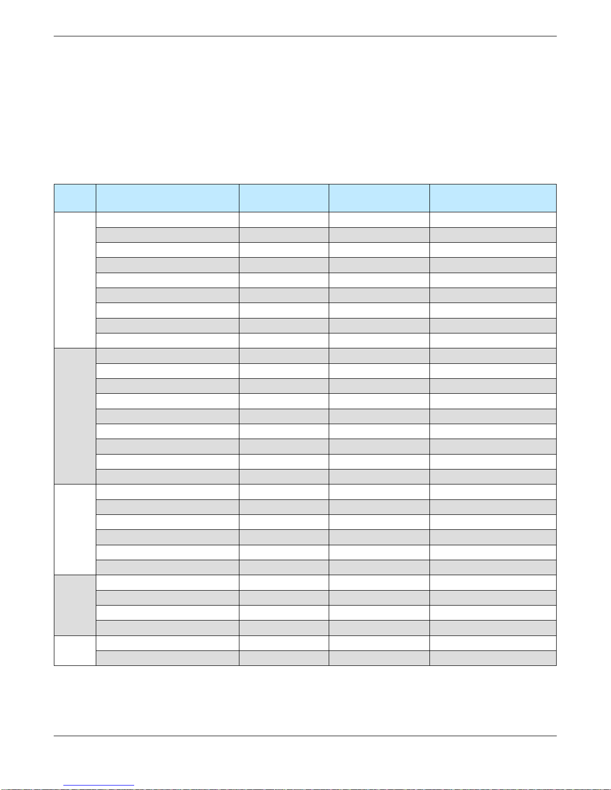
2.4 Unit Weights
The Compact Outdoor SSPA is available in a variety of frequency bands and power levels,
and have a multitude of options which makes each unit weigh slightly different from another.
The following chart, Table 2-6, outlines the weights for the most common power levels of
Compact Outdoor SSPA and additional weight add-ons for common options.
Table 2-6: Compact Outdoor SSPA Weights
Band Model
HPAC2030AC... 36.5 (16.6) +1.7 (+0.8) N/A
HPAC2040AC... 36.5 (16.6) +1.7 (+0.8) N/A
HPAC2050AC... 36.5 (16.6) +1.7 (+0.8) N/A
C-Band
Ku-Band
X-Band
S-Band
KaBa
nd
HPAC2075AC... 36.5 (16.6) +1.7 (+0.8) N/A
HPAC2100AC... 36.8 (16.7) +1.7 (+0.8) N/A
HPAC2140AC... 37.0 (16.8) +1.7 (+0.8) +1.9 (+0.9)
HPAC2200AC... 37.8 (17.2) +1.7 (+0.8) +1.2 (+0.6)
HPAC2250AC... 45.4 (20.6) +1.7 (+0.8) +1.2 (+0.6)
HPAC2300AC... 46.9 (21.3) +1.7 (+0.8) N/A
HPAK2010AC... 35.1 (16.0) +1.7 (+0.8) N/A
HPAK2020AC... 35.1 (16.0) +1.7 (+0.8) N/A
HPAK2025AC... 35.1 (16.0) +1.7 (+0.8) N/A
HPAK2035AC... 35.1 (16.0) +1.7 (+0.8) N/A
HPAK2040AC... 35.3 (16.1) +1.7 (+0.8) N/A
HPAK2050AC... 35.7 (16.2) +1.7 (+0.8) N/A
HPAK2070AC... 35.7 (16.2) +1.7 (+0.8) N/A
HPAK2100AC... 42.5 (19.3) +1.7 (+0.8) +1.2 (+0.6)
HPAK2125AC... 42.5 (19.3) +1.7 (+0.8) +1.2 (+0.6)
HPAX2060AC... 46.3 (21.1) +1.7 (+0.8) N/A
HPAX2075AC... 46.7 (21.2) +1.7 (+0.8) N/A
HPAX2100AC... 46.7 (21.2) +1.7 (+0.8) N/A
HPAX2140AC... 47.5 (21.6) +1.7 (+0.8) +1.2 (+0.6)
HPAX2200AC... 54.9 (25.0) +1.7 (+0.8) +1.2 (+0.6)
HPAX2250AC... 56.4 (25.6) +1.7 (+0.8) N/A
HPAS2050AC... 36.0 (16.4) N/A N/A
HPAS2100AC... 36.0 (16.4) N/A N/A
HPAS2200AC... 44.0 (20.0) N/A N/A
HPAS2300AC... 44.0 (20.0) N/A N/A
HPAKA040AC… 44.3 (20.2) +1.7 (+0.8) N/A
HPAKA080AC... 44.3 (20.2) +1.7 (+0.8) N/A
Base Weight
lbs (kg)
With zBUC
lbs (kg)
With 110 VAC Option
lbs (kg)
Operations Manual, HPA2, Compact Outdoor SSPA 208495 REV F 21
2.5 Compact Outdoor Mounting Kit Installation
These instructions outline how to install a Teledyne Paradise Datacom Compact Outdoor
SSPA unit onto an antenna boom, using a Universal Compact Outdoor Mounting Kit. This kit
allows installation of the Compact Outdoor SSPA on antenna booms up to 10” thick.
2.5.1 Safety Considerations
These instructions are designed to be used by a single operator. As such, several safety
issues should be kept in mind during the installation.
1. The Teledyne Paradise Datacom Compact Outdoor SSPA unit weighs approximately
36 lbs., and should be handled with care to avoid scratching the exterior coating and
compromising the unit’s corrosion resistance.
2. All bolts should be tightened to within reasonable limits to avoid stripping the threads.
3. The section of antenna boom the unit is to be mounted on should be straight, dry, and
free from corrosion or defects.
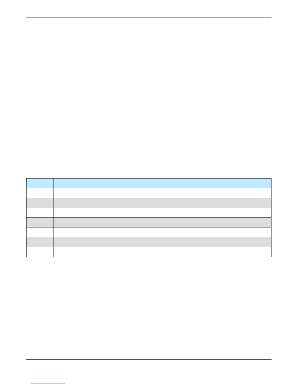
2.5.2 Inspection
On receiving the Universal Compact Outdoor Mounting Kit, inspect the contents to ensure all
parts listed in Table 2-7 are present.
Table 2-7: Mounting Kit Parts List
Item # Qty Description Part No.
1 4 Bracket, Mounting L201394-1
2 4 Uni-Strut, 13.5” Lengths L201393-1
3* 4 1/2”-13 All Thread Stud, SS 188FTS 8-11 or -15
4 4 1/2” Lock Washer 50LW188
5 16 Nut, Hex, 1/2”-13 1/2-13 Nut
6 16 Washer, Flat, Std. 1/2” MS15795-819
7 4 Bolt, Hex, 1/2”-13 x 1.25, SS MS35307-411
* Kits are supplied with two different All Thread lengths (11.0” or 15.0”) depending on the
installation. The 11-inch All Thread allows mounting on booms up to 6” diameter. The 15-inch
All Thread allows mounting on booms up to 10” diameter.
22 208495 REV F Operations Manual, HPA2, Compact Outdoor SSPA
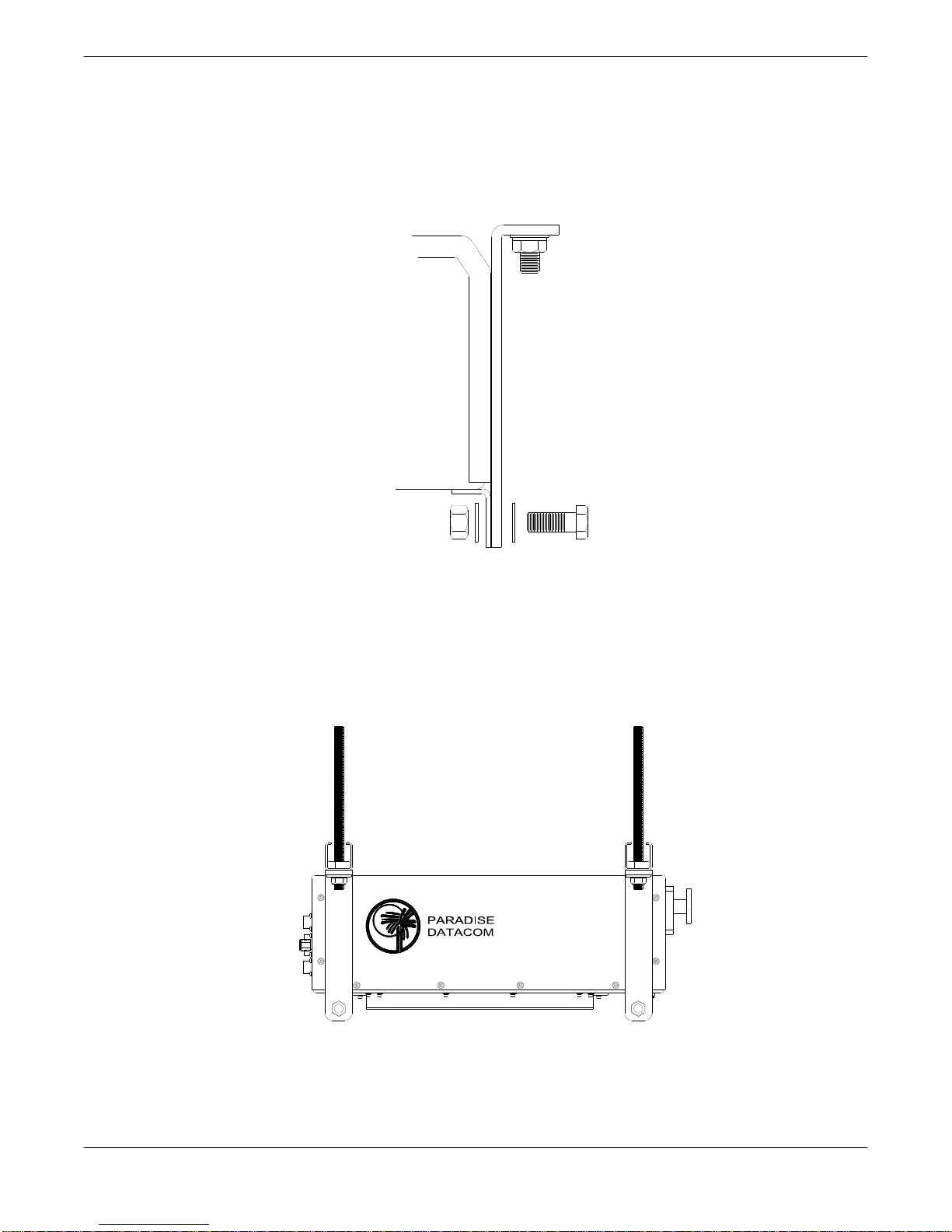
2.5.3 Installation
1. Locate the mounting studs on the bottom of the Compact Outdoor SSPA unit. Using a ½”
bolt, two flat washers, and a ½” nut, firmly bolt one mounting bracket to each mounting
stud, as shown in Figure 2-6. Be sure each bracket is vertical, and the top flange of the
mounting bracket points away from the unit.
Figure 2-6: Bolt Mounting Bracket to Unit
2. Place one piece of Uni-Strut (open channel up) at each end of the CO unit, across the
flanges of the mounting brackets, lining up the holes. For each All-Thread stud, run on a
½” nut approximately 1” from the rod end. Slip on a lock washer, and thread the short
end of the stud through the Uni-strut and mounting flange. Secure firmly in place with a
flat washer and nut. The unit should now look as shown in Figure 2-7.
Figure 2-7: Unit Ready for Boom Installation
Operations Manual, HPA2, Compact Outdoor SSPA 208495 REV F 23
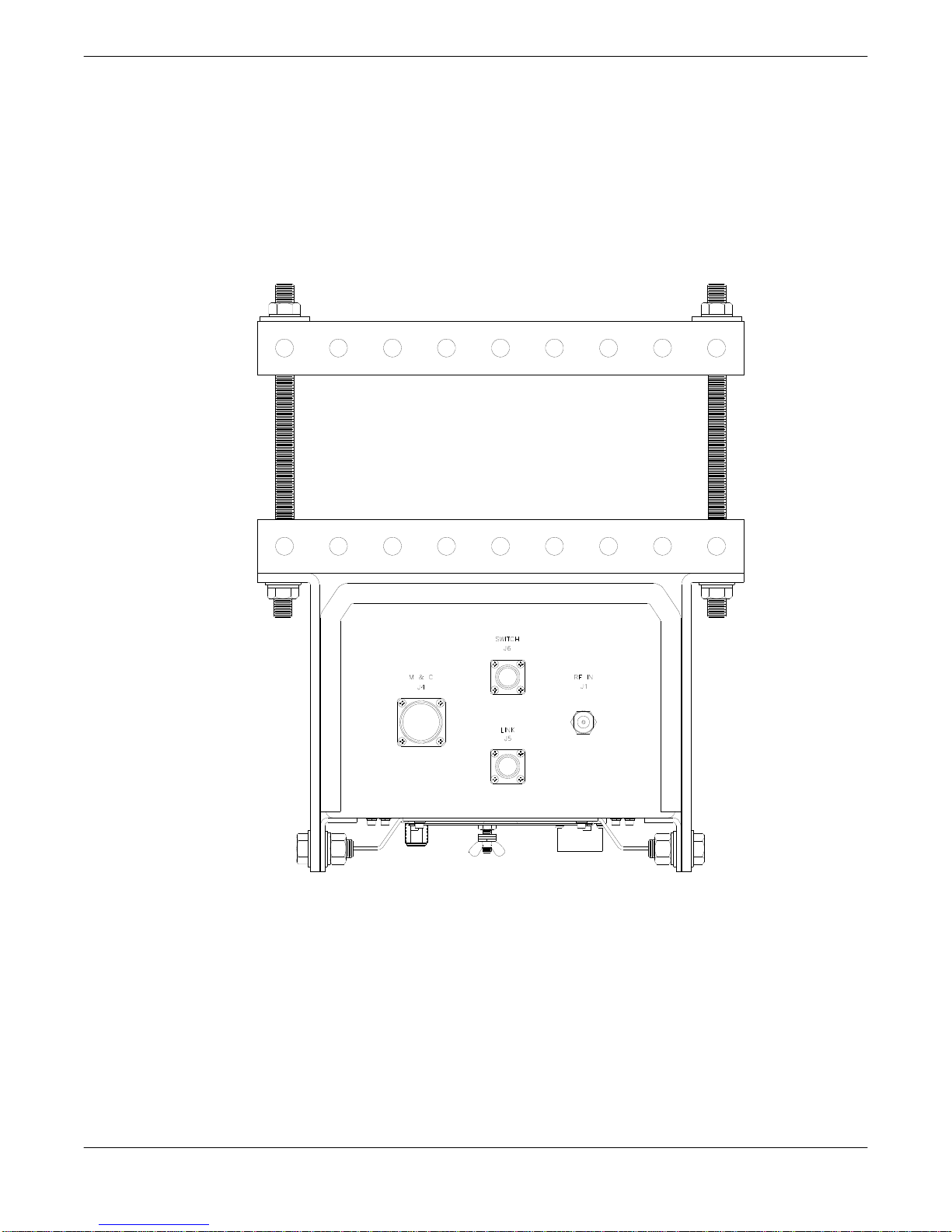
3. Bring the unit up tight under the boom (with the long axes parallel), sliding the All-Thread
studs past the sides of the boom to show above the boom top. Place the remaining pieces
of Uni-strut (open channel down) across the boom, onto the protruding All-Thread stud
ends. Secure firmly with a flat washer and ½” nut on each of the four All-Thread stud
ends. Looking from the end of the boom, the mounted unit should look as shown in Figure
2-8.
4. Connect the Compact Outdoor SSPA unit as directed elsewhere in this manual.
24 208495 REV F Operations Manual, HPA2, Compact Outdoor SSPA
Figure 2-8: CO Mount Completed
Section 3: Quick Start & Operation
3.0 Introduction
The Compact Outdoor SSPA is available with a standard RS-232/RS-485 serial communications interface or an optional Ethernet & RS-232/RS-485 interface. This section summarizes
the connections to a remote computer for various remote communications. Table 3-1 summarizes the hardware connections of Port J4 for Ethernet-capable units; Table 3-2 displays the
hardware connections of Port J4 for non-Ethernet-capable units.
3.0.1 Remote Communications Connections
Ethernet ready Compact Outdoor SSPAs can be identified by either serial number or label.
Compact Outdoor SSPAs with serial numbers greater than 300,000 are Ethernet ready. Also
Ethernet ready units have the following label affixed adjacent to the M&C connector, J4.
ETHERNET READY
Ethernet ready units can be configured for either RS-232, RS-485, or Ethernet communications. The units cannot be used with multiple communication protocols simultaneously. The
user must select one of the three formats. Non-Ethernet units can be configured for either
RS-232 or RS-485 communications. The following figures show the proper configuration of J4
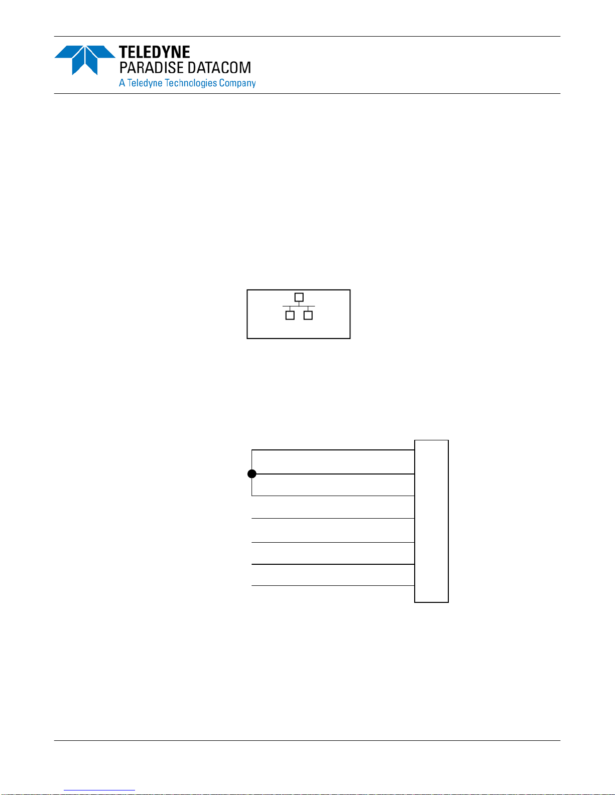
for each of the three communication formats.
Baud Select 1
Chassis Ground
TX Enable
10 BASE-T RX-
10 BASE-T RX+
10 BASE-T TX+
10 BASE-T TX-
DEFAULT IP ADDRESS: 192.168.0.9
e
V
B
H
J
X
W
J4
Figure 3-1: J4 Connections for Ethernet Communications
Operations Manual, HPA2, Compact Outdoor SSPA 208495 REV F 25
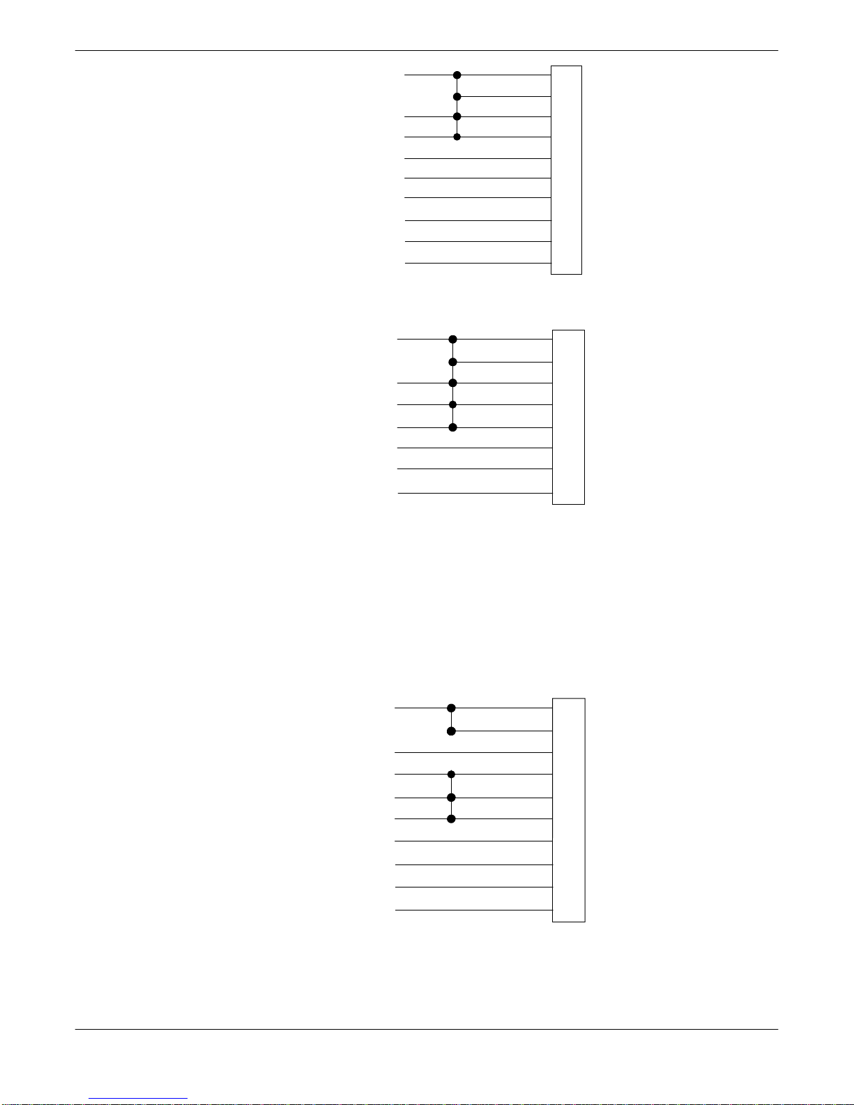
Chass is Ground
TX Enable
Baud Select 0
Baud Select 1
RS232/RS 485 Select
Isolated Return for RS232/RS485
RS485 (RX-) RS232 (RX)
RS485 (TX-) RS232 (TX)
RS485 (TX+)
RS485 (RX+)
V
B
j
e
D
d
F
E
T
U
J4
Figure 3-2: J4 Connections for RS-485 Communications
Chassis Ground
TX Enable
Baud Selec t 0
Baud Selec t 1
RS232/R S485 Select
Isolated Return for RS232/RS485
RS232 (RX)
RS232 (TX)
V
B
j
e
D
d
F
E
J4
Figure 3-3: J4 Connections for RS-232 Communications
3.0.2 Legacy Compact Outdoor SSPAs
Compact Outdoor SSPAs with serial numbers of less than 300,000 did not include isolated
grounds for RS-232/RS-485 serial communications. The remote communication connections
are slightly different and outlined in Figures 3-4 and 3-5.
Chass is Ground
TX Enable
RS232/R S485 Selec t
Baud Select 0
Baud Select 1
Chass is Ground
RS485 (RX-) RS232 (RX)
RS485 (TX-) RS232 (TX)
RS485 (TX+)
RS485 (RX+)
9600 BAUD Selection shown
V
B
D
j
e
d
F
E
T
U
J4
Figure 3-4: J4 Connections for RS-485 Communications for Serial Numbers <300,000
26 208495 REV F Operations Manual, HPA2, Compact Outdoor SSPA
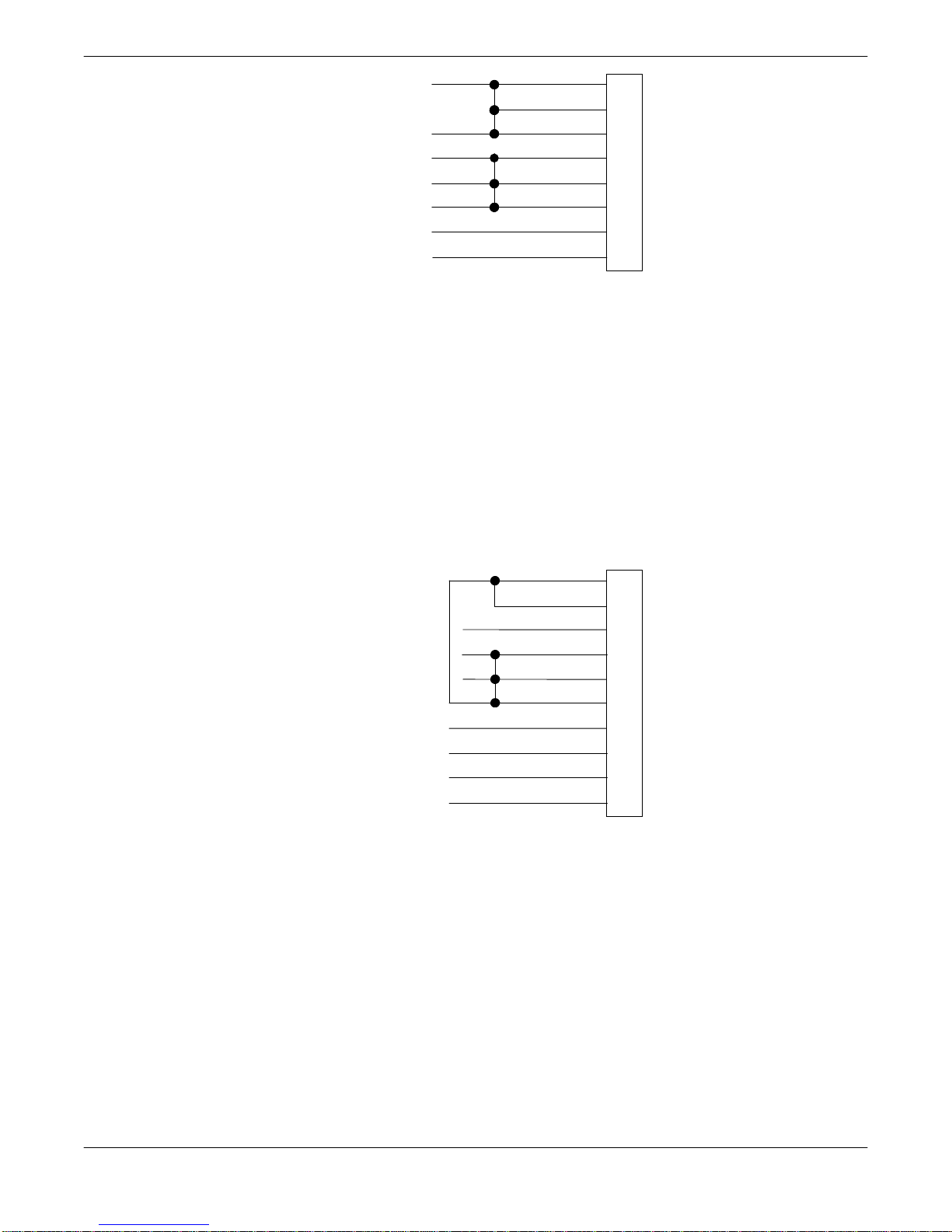
Chass is Ground
TX Enable
RS232/RS485 Select
Baud Select 0
Baud Select 1
Chass is Ground
RS232 (RX)
RS232 (TX)
9600 BAUD Selection s hown
V
B
D
j
e
d
F
E
J4
Figure 3-5: J4 Connections for RS-232 Communications for Serial Numbers <300,000
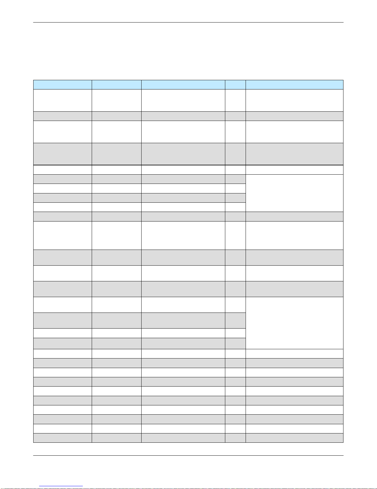
3.0.3 Compact Outdoor SSPAs in Legacy Systems
The isolated return for RS-232/RS-485 systems that exists on Compact Outdoor SSPAs with
serial numbers 300,000 and above will require an additional connection on J4 when used in
systems that have Monitor and Control cables designed to be used with units with serial
numbers < 300,000.
Figure 3-6 shows the required connection between the chassis ground and the isolated
ground (pin V to pin d).
Chassis Ground
TX Enable
RS232/RS485 Select
Baud Select 0
Baud Select 1
Isolated Return for RS232/RS485
RS485 (RX-) R S232 (RX)
RS485 (TX-) RS232 (TX)
RS485 (TX+)
RS485 (RX+)
9600 BAUD Selection shown
V
B
D
j
e
d
F
E
T
U
J4
Figure 3-6: J4 Connections for RS-485 Communications for Compact Outdoor SSPAs
of Serial Numbers >300,000 in systems with M&C cables designed for
Compact Outdoor SSPAs of Serial Numbers <300,000
If it is not possible to modify the existing cable harness or otherwise externally connect the
chassis ground Pin V to the isolated return at Pin d as shown in Figure 3-6, consult the
factory for other options.
Operations Manual, HPA2, Compact Outdoor SSPA 208495 REV F 27
3.1 Port J4 Pin-Outs
Table 3-1 shows the pin-outs for the J4 Monitor & Control Connector for Ethernet capable
units.
Table 3-1: Monitor & Control Connector (J4) Pin-Out (Ethernet capable)
Signal Type Function Pin Notes
Unit powers up muted;
Mute Input Closure to Ground Disables DC Power to SSPA B
Auxiliary Input Closure to Ground Auxiliary Input P
Closed on Fault
Summary Alarm Form C Relay
Auxiliary Alarm Form C Relay
Low RF Fault Output Open Collector High on Fault G Requires external pull-up
10 Base-T TX- W
10 Base-T RX- H
10 Base-T RX+ J
10 Base-T TX+ X
Spare Input Analog Input S +5V max.
RF Power Detector
OR
Fan Speed Control 1
Gain Adjust Input Analog Input
Block Up Converter
Alarm
RS232 / RS485
Select
RS 485 TX-
or RS232 OUT
RS 485 RX-
or RS232 IN
RS 485 TX+ Serial TX Output Serial Link Data Port T
RS 485 RX+ Serial RX Input Serial Link Data Port U
GND Signal Ground Common Signal Return V Chassis ground
GND Signal Ground Isolated Comm Ground d Ground for Signals D, E, & F
Baud Select 0 Closure to Gnd Select Baud Rate & Protocol j
Baud Select 1 Closure to Gnd Select Baud Rate & Protocol e
PGM Switch Flash Firmware Port g Reserved for Programming
PGM CLK Flash Firmware Port c Reserved for Programming
PGM-Sout Flash Firmware Port K Reserved for Programming
PGM-Sin Flash Firmware Port Y Reserved for Programming
PGM +5V Flash Firmware Port h Reserved for Programming
PGM Enable Flash Firmware Port C Reserved for Programming
1
All GaN Compact Outdoor SSPAs are fitted with the Fan Speed Control option.
Analog Output
Open Collector High on Fault f Requires external pull-up
Closure to Ground Selects Serial Communication D
Serial TX Output Serial Link Data Port E
Serial RX Input Serial Link Data Port F
Common
Open on Fault
Closed on Fault
Common
Open on Fault
Relative Indication
of RF Output Power
OR
Fan Speed Control
Adjusts Amplifier Gain
over 20dB range
L
a
b
N
Z
M
R
A
This line must be pulled to ground
(V) to enable amplifier
L-a : normally open
a-b : normally closed
N-Z : normally open
Z-M: normally closed
See Section 10
+4.0 VDC at Psat (RF Power Detector)
OR
No connection (Fan Speed Control)
2.5 vdc = Max Gain 75 dB
0.5 vdc = Min Gain 55 dB
Default is RS 485; pull to ground (d)
to enable RS 232
See Section 10
Refer to Table 10-1
Refer to Table 10-1
28 208495 REV F Operations Manual, HPA2, Compact Outdoor SSPA
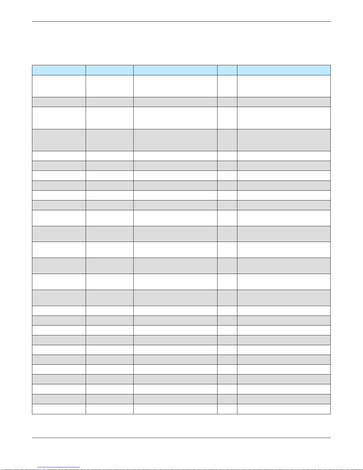
Table 3-2 shows the pin-outs for the J4 Monitor & Control Connector for units that cannot
communicate via Ethernet (units with serial numbers prior to 300,000).
Table 3-2: Monitor & Control Connector (J4) Pin-Out (Non-Ethernet)
Signal Type Function Pin Notes
Unit powers up muted,
Mute Input Closure to Ground Disables DC Power to SSPA B
Auxiliary Input Closure to Ground Auxiliary Fault Input P
Closed on Fault
Summary Alarm Form C Relay
Auxiliary Alarm Form C Relay
Open Collector High on Fault W Reserved
Auxiliary Alarm Open Collector High on Fault G Requires external pull-up
Voltage Alarm Open Collector High on Fault H Requires external pull-up
Current Alarm Open Collector High on Fault J Requires external pull-up
Temperature Alarm Open Collector High on Fault X Requires external pull-up
Spare Fault Open Collector High on Fault S Requires external pull-up
RF Power Detector Analog Output
Gain Adjust Input Analog Input
Block Up Converter
Alarm
RS232 / RS485
Select
RS 485 TX- or
RS232 OUT
RS 485 RX- or
RS232 IN
RS 485 TX+ Serial TX Output Serial Link Data Port T
RS 485 RX+ Serial RX Input Serial Link Data Port U
GND Signal Ground Common Signal Return V, d
Baud Select 0 Closure to Gnd Select Baud Rate & Protocol j
Baud Select 1 Closure to Gnd Select Baud Rate & Protocol e
PGM Switch Flash Firmware Port g Reserved for Programming
PGM CLK Flash Firmware Port c Reserved for Programming
PGM-Sout Flash Firmware Port K Reserved for Programming
PGM-Sin Flash Firmware Port Y Reserved for Programming
PGM +5V Flash Firmware Port h Reserved for Programming
PGM Enable Flash Firmware Port C Reserved for Programming
Open Collector High on Fault f Requires external pull-up
Closure to Ground Selects Serial Communication D
Serial TX Output Serial Link Data Port E
Serial RX Input Serial Link Data Port F 9600 default Baud Rate
Relative Indication of RF Output
Adjusts Amplifier Gain over 20dB
Common
Open on Fault
Closed on Fault
Common
Open on Fault
Power
range
N
M
R +4.0 vdc at Psat
A
This line must be pulled to ground
(V or d) to enable amplifier
L
a
b
Z
Default is RS 485; pull to ground (V)
L-a : normally open
a-b : normally closed
N-Z : normally open
Z-M: normally closed
2.5 vdc = Max Gain 75 dB
0.5 vdc = Min Gain 55 dB
to enable RS 232
Refer to Table 10-1
Refer to Table 10-1
Operations Manual, HPA2, Compact Outdoor SSPA 208495 REV F 29

3.1.1 Amplifier Enable (Mute/Unmute) (J4)
The Compact Outdoor Amplifier has no on/off switch or circuit breaker in the AC Input path.
As soon as AC power is applied to J7, the unit’s power supplies and microcontroller are
enabled. The operator will be able to observe the forced convection cooling fans running.
However, the internal amplifier module is disabled until the Mute Line Input (J4, Pin B) is
pulled to Ground (J4, Pin V).
If it is desired to have the RF enabled every time the AC input is applied, a permanent
connection can be made from J4-Pin B and Pin V.
3.1.2 Gain Adjust Input (J4)
The Gain Adjust Input allows an analog voltage that is applied between (J4, Pin A) and
Ground (J4, Pin V) to control the gain of the amplifier. The gain is adjustable over a 20 dB
range with 0.1 dB resolution. The applied voltage is directly proportional to amplifier gain.
2.5 VDC = Maximum Gain: 75 dB
0.5 VDC = Minimum Gain: 55 dB
The Compact Outdoor SSPA is factory default to have maximum gain with no analog gain
adjust. The gain adjustment must be enabled by running the setup program from a host PC.
This prohibits any accidental gain adjustments that may occur from unintentional analog
voltages that may be present on the Gain Adjust Control J4, Pin A.
The gain is also adjustable using a host PC and the supplied Teledyne Paradise Datacom
Universal M&C program. See the Serial I/O Section for details on Serial Control.
3.1.3 Alarms (J4)
A variety of alarm signals are present at the M&C connector, J4. Both Form-C relays and
open collector outputs are available. An amplifier summary alarm is available in both Form C
relay and open collector output. Detailed internal faults are available in open collector form
and include: voltage, current, and over-temperature.
3.1.3.1 Summary Alarm (J4) Form C Contacts
The Summary Alarm is accessible in both Form C relay and open collector format. The form
C relay is “energized” under normal operating conditions and “deenergized” when a fault
condition exists.
3.1.3.2 Auxiliary Alarm (J4) Form C Contacts
The Auxiliary Alarm relay is an end user alarm that can be used to signal an alarm condition
that is dependent on the state of the Auxiliary Input (J4, Pin P).
The Auxiliary Input is a contact closure to ground. When this input is pulled to ground the
Auxiliary Alarm relay is energized (Normal State). When the Auxiliary Input is open circuited
the Auxiliary Alarm relay is de-energized (Alarm State).
30 208495 REV F Operations Manual, HPA2, Compact Outdoor SSPA
 Loading...