

Teledyne Century 3000 CVE-16 Operation And Maintenance Manual
QCEC
“Dependability Defined”
Century 3000 CVE-16
Wall-Mount Indoor Wastewater Sampler
Operations and Maintenance Manual
v2A June 13, 2016
Part Number: 69-2303-411
4700 Superior Street • Lincoln, NE 68504
(402) 464-0231 • (800) 228-4373
www.teledyneisco.com • isco.info@teldeyne.com


August 2017
TO: Purchaser of QCEC Brand Products
FROM: Teledyne ISCO
We hope that you find this recent product purchase meets your needs. We wanted to update
you that the QCEC product you purchased is now manufactured by Teledyne ISCO and is
backed by Teledyne ISCO’s commitment to quality products and exceptional customer
service.
Teledyne Isco, a world leader in automatic water sampling and open channel flow monitoring
products, acquired in late April 2017 the QCEC line of water & wastewater automatic samplers
and flowmeters. With the addition of this sampling vacuum pump technology, we are able to
offer a broader sampler product offering to meet customers’ needs.
Teledyne Isco has been in business for over 50 years manufacturing a wide range of products
for professionals working in water pollution monitoring and abatement, engineers and
managers involved with wastewater process control, and scientists involved in field and
laboratory work. We take pride in the fact that the products we produce are used by our
customers to improve the quality of life on Earth.
We offer all our customers responsive, competent, and excellent service and support. Our
customers are the most important part of our business, and we work tirelessly to ensure your
complete satisfaction. Provided below are key contact information so that you can reach us
at your convenience.
Water & Wastewater Product Support:
Telephone (402) 853-5350
Toll Free (USA) (866) 298-6174
Email IscoEPS@teledyne.com
Teledyne ISCO
4700 Superior Street
PO Box 82531
Lincoln, NE 68501
Telephone (402) 464-0231
Fax (402) 464-0318
Toll Free (USA) (800) 228-4373
Email information request iscoinfo@teledyne.com
Website www.teledyneisco.com


Before returning any instrument for repair, please call, fax, or e-mail the Teledyne Isco Service
Teledyne Isco Two Year Limited Factory Service Warranty*
This warranty exclusively covers Teledyne Isco
instruments, providing a two-year limited warranty
covering parts and labor.
Any instrument that fails during the warranty period due to
faulty parts or workmanship will be repaired at the factory
at no charge to the customer. Teledyne Isco’s exclusive
liability is limited to repair or replacement of defective
instruments. Teledyne Isco is not liable for consequential
damages.
Teledyne Isco will pay surface transportation charges both
ways within the 48 contiguous United States if the
instrument proves to be defective within 30 days of
shipment. Throughout the remainder of the warranty period,
the customer will pay to return the instrument to Teledyne
Isco, and Teledyne Isco will pay surface transportation to
return the repaired instrument to the customer. Teledyne
Isco will not pay air freight or customer’s packing and
crating charges. This warranty does not cover loss, damage,
or defects resulting from transportation between the
customer’s facility and the repair facility.
The warranty for any instrument is the one in effect on date
of shipment. The warranty period begins on the shipping
date, unless Teledyne Isco agrees in writing to a different
date.
Excluded from this warranty are normal wear; expendable
items such as desiccant, pH sensors, charts, ribbon, lamps,
tubing, and glassware; fittings and wetted parts of valves;
check valves, pistons, piston seals, wash seals, cylinders,
pulse damper, diaphragms, inlet lines and filter elements,
and damage due to corrosion, misuse, accident, or lack of
proper maintenance. This warranty does not cover products
not sold under the Teledyne Isco trademark or for which any
other warranty is specifically stated.
No item may be returned for warranty service without a
return material authorization number issued by Teledyne
Isco.
This warranty is expressly in lieu of all other warranties
and obligations and Teledyne Isco specifically disclaims
any warranty of merchantability or fitness for a
particular purpose.
The warrantor is Teledyne Isco, 4700 Superior, Lincoln, NE
68504, U.S.A.
* This warranty applies to the USA and countries where Teledyne Isco does not have an authorized dealer.
Customers in countries outside the USA, where Teledyne Isco has an authorized dealer, should contact their
Teledyne Isco dealer for warranty service.
Department for instructions. Many problems can often be diagnosed and corrected over the
phone, or by e-mail, without returning the instrument to the factory.
Instruments needing factory repair should be packed carefully, and shipped to the attention of
the service department. Small, non-fragile items can be sent by insured parcel post. PLEASE
BE SURE TO ENCLOSE A NOTE EXPLAINING THE PROBLEM.
Shipping Address: Teledyne Isco - Attention Repair Service
4700 Superior Street
Lincoln, NE 68504 USA
Mailing Address: Teledyne Isco
PO Box 82531
Lincoln, NE 68501 USA
Phone: Repair service: (800) 775-2965 (lab instruments)
Sales & General Information: (800) 228-4373 (USA & Canada)
Fax: (402) 465-3001
Email: IscoService@teledyne.com
January 10, 2017 P/N 60-1002-041
(866) 298-6174 (samplers & flow meters)


Century 3000 CVE-16 Wall-Mount Indoor Wastewater Sampler
Table of Contents
Warranty ................................................................................................................................................................................. 2
Table of Contents ............................................................................................................................................................ 3
List of Illustrations .......................................................................................................................................................... 6
List of Tables ...................................................................................................................................................................... 6
Configuration Quick Start........................................................................................................................................... 7
Composite Sample Storage Quick Start ................................................................................................... 9
Operation Quick Start ............................................................................................................................................... 10
Chapter 1: Introduction ........................................................................................................................................... 11
1.1: Physical Description ................................................................................................................................ 12
1.1.1: Sample Collection System ....................................................................................................... 12
1.1.2: Sampling Control System......................................................................................................... 12
1.1.2.1: User Interface Panel ....................................................................................................... 13
1.1.2.2: Inputs and Outputs ......................................................................................................... 13
1.1.3: Sample Storage System ............................................................................................................ 13
1.2: Sampling Programs ................................................................................................................................. 14
Chapter 2: Installation .............................................................................................................................................. 15
2.1: Sampling Line Connection ................................................................................................................. 15
2.2: Positioning Considerations ................................................................................................................. 16
2.3: Sample Size Adjustment ...................................................................................................................... 16
2.3.1: Velocity Valve Adjustment ....................................................................................................... 16
2.4: Field I/O Connections .......................................................................................................................... 17
2.4.1: Flow Inputs ......................................................................................................................................... 17
2.4.2: Relay Outputs .................................................................................................................................. 18
2.4.3: Float Input .......................................................................................................................................... 18
Chapter 3: User Interface Panel ....................................................................................................................... 19
3.1: Menu System ............................................................................................................................................... 20
3.2: Administration Menu .............................................................................................................................. 22
3.2.1: Administration Password ........................................................................................................... 22
3.2.2: Clock Settings .................................................................................................................................. 24
3.2.3: LCD Brightness ................................................................................................................................ 25
3.2.4: Archival Data Administration ................................................................................................. 26
3.2.5: Set ID Number ................................................................................................................................. 27
3.2.6: Set Volumetric Units ................................................................................................................... 27
Chapter 4: Sampling Program Configuration ............................................................................................ 28
4.1: Program Selection ................................................................................................................................... 28
4.2: Program Configuration Groups ....................................................................................................... 29
4.3: Sampling Cycle Settings ...................................................................................................................... 30
4.3.1: Pre-Sampling Purge Duration ................................................................................................ 30
4.3.2: Sampling Time ................................................................................................................................. 31
4.3.3: Post-Sampling Purge Duration .............................................................................................. 31
4.3.4: Line Conditioning Rinses .......................................................................................................... 32
4.3.5: Incomplete Sample Recycling ................................................................................................ 33
4.3.6: Consecutive Sampling ................................................................................................................. 33
4.4: Sampling Intervals .................................................................................................................................... 34
4.4.1: Timed Interval Sampling ........................................................................................................... 35
June 13, 2016 Revision 2A page 3

Century 3000 CVE-16 Wall-Mount Indoor Wastewater Sampler
4.4.1.1: Fixed Length Time Intervals ...................................................................................... 35
4.4.1.2: Variable Length Time Intervals ................................................................................ 36
4.4.2: Flow Interval Sampling ............................................................................................................... 37
4.4.2.1: Analog Flow Input............................................................................................................. 38
4.4.2.1.1: Fixed Volume Flow Intervals ............................................................................. 39
4.4.2.1.2: Variable Volume Flow Intervals....................................................................... 39
4.4.2.2: Pulsing Flow Input ............................................................................................................ 40
4.4.2.2.1: Fixed Pulses Flow Intervals ................................................................................ 40
4.4.2.2.2: Variable Pulses Flow Intervals ......................................................................... 41
4.4.3: Time+Flow Interval Sampling ................................................................................................. 41
4.5: Bottle Options ............................................................................................................................................ 42
4.6: Program Run Options ........................................................................................................................... 43
4.6.1: Automatic Rerun ............................................................................................................................. 44
4.6.2: Delayed Start.................................................................................................................................... 44
4.6.3: Fault Option ...................................................................................................................................... 45
4.6.4: Float Option ...................................................................................................................................... 45
4.6.5: Timed Stop ........................................................................................................................................ 46
4.6.6: Bottle Limit Override ................................................................................................................... 47
4.7: Program Events.......................................................................................................................................... 48
4.7.1: Reviewing Scheduled Events .................................................................................................. 48
4.7.2: Adding and Editing Events ...................................................................................................... 49
4.7.3: Deleting Events ................................................................................................................................ 51
4.7.4: Disabling Events .............................................................................................................................. 52
Chapter 5: Sampler Operation ........................................................................................................................... 53
5.1: Ready State ................................................................................................................................................. 54
5.2: Sampler Conditions ................................................................................................................................. 55
5.3: Starting the Selected Program ....................................................................................................... 55
5.3.1: Timed-Delay Starting ................................................................................................................... 55
5.3.2: Float-Delayed Starting ................................................................................................................ 56
5.3.3: Timed Starting ................................................................................................................................. 56
5.3.3.1: Timed State .......................................................................................................................... 57
5.3.4: Scheduled Starting ....................................................................................................................... 57
5.4: Running State ............................................................................................................................................. 58
5.4.1: Sampling Intervals ......................................................................................................................... 59
5.4.2: Sample Container Screens ...................................................................................................... 59
5.4.3: Sampling Cycle ................................................................................................................................ 60
5.4.3.1: Incomplete Sample Recycling ................................................................................... 61
5.4.3.2: Manual Sampling ............................................................................................................... 62
5.5: Paused and Halted States ................................................................................................................ 62
5.5.1: Float Suspended Sampling ..................................................................................................... 63
5.6: Stopping the Program ........................................................................................................................... 64
5.6.1: Continuous Operation ................................................................................................................ 64
5.7: Reviewing Archived Data ..................................................................................................................... 65
Chapter 6: Sampler Maintenance ..................................................................................................................... 68
6.1: Cleaning the Sampler ............................................................................................................................ 68
6.2: Compression/Vacuum Pump ............................................................................................................ 68
6.3: Fuse ................................................................................................................................................................... 68
June 13, 2016 Revision 2A page 4

Century 3000 CVE-16 Wall-Mount Indoor Wastewater Sampler
6.4: Troubleshooting Tips ............................................................................................................................. 69
Appendix A: Controller Capabilities .................................................................................................................. 71
A.1: Overview ......................................................................................................................................................... 71
A.1.1: Supervisory Routine (Ready State) .................................................................................... 71
A.1.2: Menu System Outline ................................................................................................................. 72
A.2: Inputs and Outputs ................................................................................................................................ 74
A.2.1: Run-Status Output ........................................................................................................................ 74
A.2.2: Alarm Output .................................................................................................................................... 74
A.2.3: Flow Input ........................................................................................................................................... 75
A.2.3.1: Remote Sample Initiation ............................................................................................ 75
A.2.4: Float Input .......................................................................................................................................... 76
A.2.4.1: Factory Menu Float Setting ....................................................................................... 76
A.2.5: Liquid Sensor ................................................................................................................................... 77
A.2.6: Sampling Outputs .......................................................................................................................... 77
A.3: Sampling Program.................................................................................................................................... 78
A.3.1: CVE-16 Sampling Cycle ............................................................................................................. 78
A.3.1.1: Sample Recycling .............................................................................................................. 79
A.3.2: Sampling Intervals ......................................................................................................................... 80
A.3.2.1: Variable Intervals ............................................................................................................... 80
A.3.3: Bottle Options.................................................................................................................................. 81
A.3.4: Delayed Starting ............................................................................................................................. 82
A.3.5: Timed Stopping ............................................................................................................................... 82
A.3.6: Scheduled Events .......................................................................................................................... 83
A.3.7: Data Archiving.................................................................................................................................. 84
Appendix B: Replacement Parts .......................................................................................................................... 85
June 13, 2016 Revision 2A page 5

Century 3000 CVE-16 Wall-Mount Indoor Wastewater Sampler
List of Illustrations
Figure 1-1: CVE-16 Wall-Mounted Sampler Component Locations ....................................... 11
Figure 2-1: Flow Input Connections ............................................................................................................. 17
Figure 2-2: Relay Output and Float Input Connections ................................................................ 18
Figure 3-1: User Interface Panel.................................................................................................................... 19
Figure 6-1: QLS Compressor/Vacuum Pump and Service Kit .................................................. 68
Figure A-1: CVE-16 Sample Chamber Pressure Sequencing ....................................................... 77
Figure A-2: CVE Sampling Cycle .................................................................................................................... 78
Figure A-3: Basic Sample Timing Diagram ............................................................................................. 80
Figure B-1: CVE-16 Sample Chamber Parts ........................................................................................... 87
List of Tables
Table 5-1: User Interface Panel and Icons .......................................................................................... 53
Table A-1: Available Program Event Types ........................................................................................... 83
Table B-1: Electrical System Parts .............................................................................................................. 85
Table B-2: Sampling Control System Parts ........................................................................................... 85
Table B-3: Vacuum/Pressurization System Parts .............................................................................. 86
Table B-4: Intake Line Parts ............................................................................................................................ 86
Table B-5: Sample Chamber Parts .............................................................................................................. 86
June 13, 2016 Revision 2A page 6
Century 3000 CVE-16 Wall-Mount Indoor Wastewater Sampler
Quick Start
Configuration Quick Start
The following sample procedure would configure a CVE-16 sampler’s program 1 to collect
samples at 20 minute intervals:
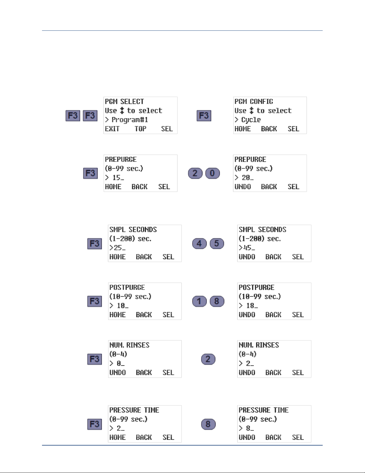
1. Power up the sampler to display its Program 1 READY screen, then press F3 three times to
access that program’s sampling Cycle settings:
2. Press F3 again to display the PREPURGE setting. Then type the number of seconds the
sample chamber should be pressurized to clear the intake prior to each sample (e.g., 20):
3. Press F3 to accept that Prepurge duration and view the SAMPLE SECONDS. Then type the
number of seconds the sample chamber should be depressurized to fill it with wastewater
(e.g., 45):
4. Press F3 to accept that setting and view the POSTPURGE time. Then type the number of
seconds the chamber should be pressurized to clear the intake after each sample (e.g., 18):
5. Press F3 to accept that setting and view the number of times the intake line should be
rinsed prior to each sample. Then type the desired NUMBER of RINSES (e.g., 2):
6. Press F3 to accept that setting. If it is not zero, the rinse cycle PRESSURE TIME will then
be displayed. Then type the number of seconds each rinse should pressurize the sample
chamber (e.g., 8):
June 13, 2016 Revision 2A page 7
Century 3000 CVE-16 Wall-Mount Indoor Wastewater Sampler Quick Start
or
or
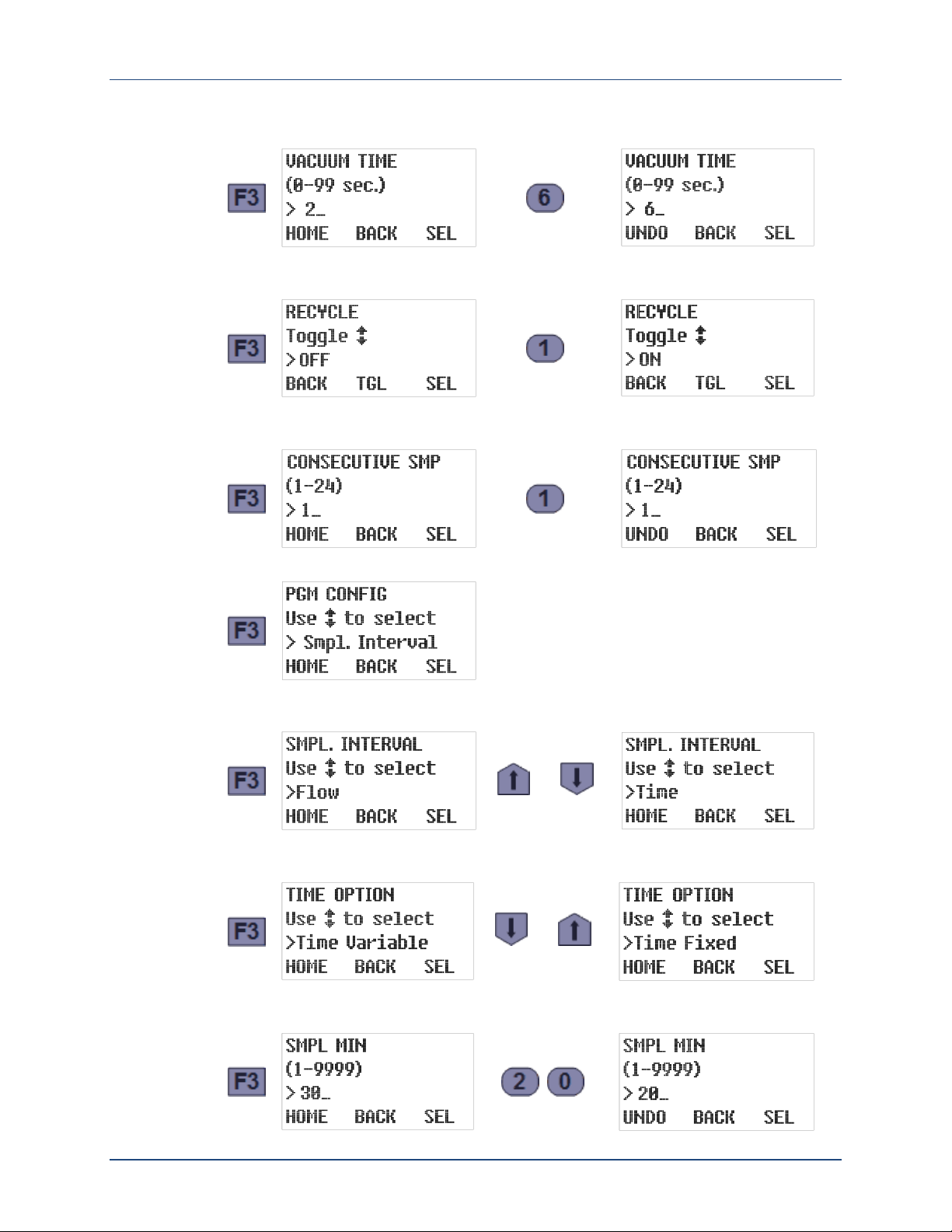
7. Press F3 to accept that setting and view the rinse cycle VACUUM TIME. Then type the
number of seconds each rinse should suction in wastewater (e.g., 6):
8. Press F3 to accept that setting and view the RECYCLE setting. Then type 0 to disable or 1
to enable the incomplete sample retry feature:
9. Press F3 to accept that setting and view the CONSECUTIVE SAMPLING setting. To draw just
one sample per interval, type 1 (if necessary) to disable that feature:
10. Press F3 to accept that setting and return to the PROGRAM CONFIG menu:
11. Press F3 to view the selected SAMPLING INTERVAL type. To change it, use the Up or Down
key to scroll to the desired interval type (e.g., timed intervals):
12. Press F3 to accept that setting and view its current TIME OPTION. To change it, use the
Up or Down key to scroll to the desired option (e.g., fixed time intervals):
13. Press F3 to accept that option and view its current SAMPLE MINUTES setting. Then type the
desired new interval duration (e.g., 20 minutes):
June 13, 2016 Revision 2A page 8
Century 3000 CVE-16 Wall-Mount Indoor Wastewater Sampler
or
after
16 hours
(48 samples)
Quick Start
Composite Sample Storage Quick Start
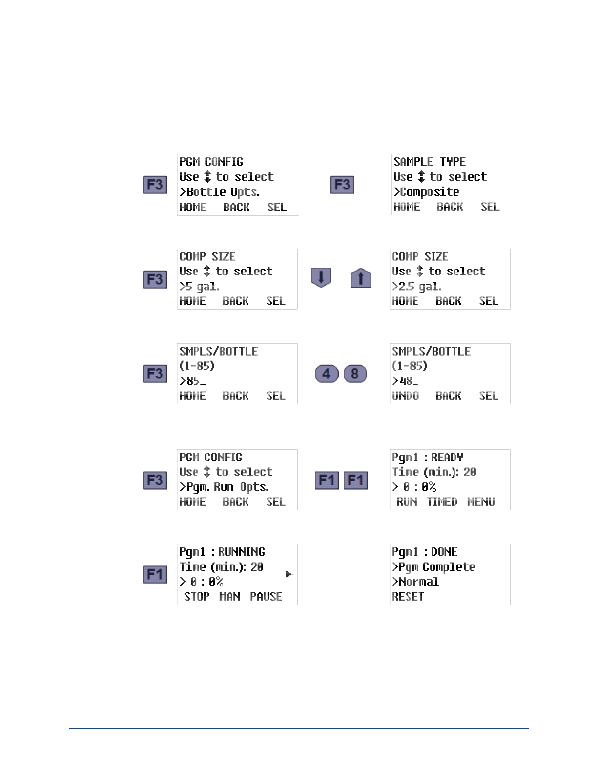
The following additional steps would configure a composite sampler to collect those samples
for 16 hours, deposit all 48 of them into a 2.5-gallon container, and then stop:
14. Press F3 twice to accept that interval, return to the PROGRAM CONFIG menu, and display
the installed SAMPLE STORAGE TYPE (always composite for wall-mount samplers):
15. Press F3 to accept that setting and view the COMPOSITE SIZE setting. Then use the Up or
Down key to scroll to the installed sample container size (e.g., 2.5 gallons):
16. Press F3 to accept that setting and view the number of samples the container is currently
set to receive. Then type the number of samples you want the program to collect (e.g., 48):
17. Press F3 to accept that setting and return to the PROGRAM CONFIG menu. Assuming you
don’t want to enable any PROGRAM RUN OPTIONS (which are all disabled by default), press
F1 twice to display the PROGRAM READY screen:
18. Twenty minutes before the first sample is to be drawn, press F1 to start the sampling
program. Barring unforeseen problems, that program would then run for 16 hours and stop:
19. You should then replace the sample container with an empty one and press F1 to reset
the program. Then repeat Step 19 twenty minutes before you want to start the next day’s
sampling.
June 13, 2016 Revision 2A page 9
Century 3000 CVE-16 Wall-Mount Indoor Wastewater Sampler Quick Start
sampler
powers up
interval
reaches
100%
or
after last
sample is
collected
OR
if composite
container
filled up
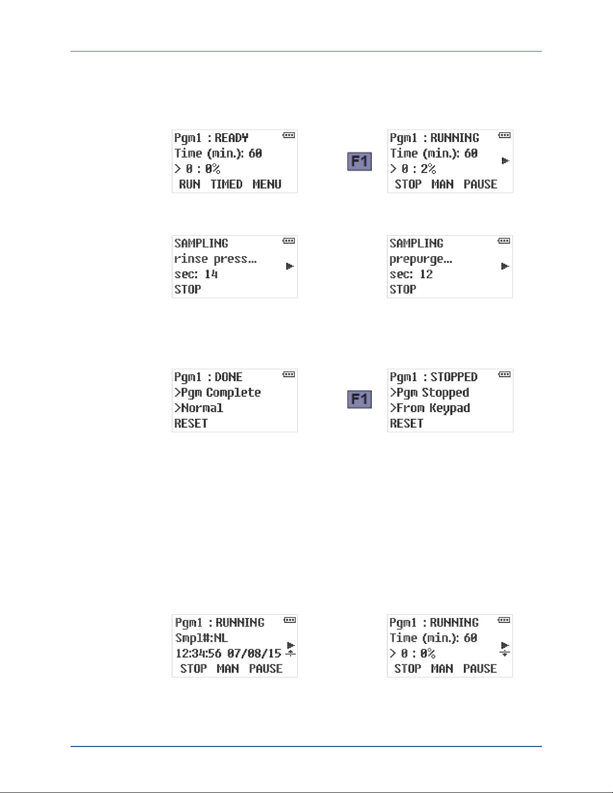
Operation Quick Start
When powered up, the controller first displays one of its Ready screens (see page 54). All you
need to do is start the indicated sampling program by pressing the RUN [F1] key:
The indicated time or flow interval counter will then accumulate until it reaches 100 percent of
its target value, at which time the sampling cycle will be initiated (see page 60):
After the sample has been discharged to its storage container, the previously-displayed Running
screen will reappear. The program will continue running until the specified number of samples
has been collected, then stop and display its DONE screen. Alternately, you can manually stop
it at any time by pressing the STOP [F1] key:
In either case, the program’s sample counters must then be reset (by pressing the RESET [F1]
key) before another round of sampling can be initiated. Before doing so, remove the samples
and install an empty container or bottle carousel.
The unit’s operation can be further simplified
to “Program Continue”). The program would then continue sampling indefinitely, without requiring
anyone to ever press the RESET [F1] key.
As the program would then have no way of knowing how many samples it has discharged since
the container was last emptied, the sample count screen (see page 59) merely indicates “NL”
(no limit). However, a composite sampler equipped with a bottle-full float switch would suspend
its interval counters (and display a downward-pointing float icon) if that switch ever opened,
then restart them from zero as soon the container was replaced (thus reclosing the switch):
by setting the Bottle Limit option (see page 47)
June 13, 2016 Revision 2A page 10
Century 3000 CVE-16 Wall-Mount Indoor Wastewater Sampler Introduction
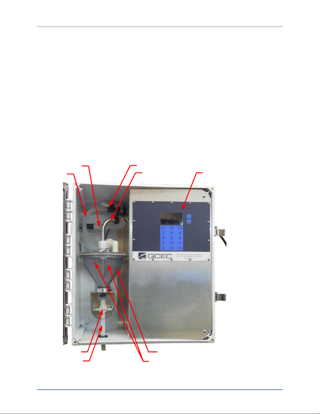
Intake Tube
Pinch Valve
Discharge Line
Sample Chamber
User
Interface
Pump, Solenoid Valve, Liquid Sensor Controller,
Transformer and Fuse Holder are behind the partition
Velocity Limiter
Intake Line
Vacuum
Line
Liquid Sensor Electrodes
Chapter 1: Introduction
CVE-16 Wall Mount Samplers collect constant volume wastewater samples at programmed time
or flow intervals and deposit them into external composite sample containers. Their vacuum
pumps provide long-term consistent sampling with vertical lifts of up to 23 feet (28 feet with
the quick-lift pump option), with no need to frequently replace the internal tubes that render
peristaltic pumps inconsistent, unreliable and costly to maintain.
⦸
The CVE-16 vacuum system cannot be used to sample pressurized wastewater streams, or
open streams whose surfaces are higher than the sampler. Attempting to do so will ruin
the sampler by filling it with water.
If you have any questions or suggestions, feel free to call QCEC at 1-515-266-2268 and ask
for wastewater sampling technical support.
Figure 1-1: CVE-16 Wall-Mounted Sampler Component Locations
June 13, 2016 Revision 2A page 11

Century 3000 CVE-16 Wall-Mount Indoor Wastewater Sampler Introduction
1.1: Physical Description
Each CVE-16 Wall Mount Sampler includes sample collection and sampling control systems
mounted in a durable plastic housing with a clear access door. The interior of that housing
is divided by an aluminum partition that protects the electrical components and provides a
mounting surface for the user interface panel.
Unlike our other sampler models, these units do not include sample storage compartments and
containers. Each must instead be provided with a suitable customer-provided composite sample
container, which might or might not need to be housed in a refrigerated compartment.
1.1.1: Sample Collection System
The sample collection system has the following major components (see Figure 1-1):
A clear plastic sample chamber with an adjustable wastewater inlet tube (whose projection
into the chamber determines the sample size) and a discharge-tube pinch valve.
A liquid sensor the controller uses to determine when the chamber is full.
A 120 VAC piston air compressor/vacuum pump connected to that chamber by a four-way
solenoid valve, which alternately evacuates and pressurizes the sample chamber in order to
draw wastewater in and force it back out.
A pump discharge pressure regulator and an intake velocity-limiting valve.
A 3/8 inch clear stream sampling tube that extends to an unpressurized wastewater stream
whose surface is at a lower elevation than the sampler.
Each sample is collected by:
1. Blowing air through the chamber to clear the sample intake line.
2. Sucking water into the chamber until it rises above the top of the intake tube.
3. Blowing any water that is above the intake tube back out through the intake line.
4. Opening the discharge valve to drain the remaining consistant-volume sample into the
sample container.
The velocity-limiting valve is mounted to the partition, while the liquid sensor’s controller, pump,
solenoid and pressure regulator are located behind it. For 240VAC units, that protected area
also houses a 240-to-120 VAC transformer.
1.1.2: Sampling Control System
The CVE-16 sampling control system includes two circuit boards that are referred to as the
logic and power boards. They collectively provide the following features:
a 32-bit microcontroller that can run any of six sampling programs
a backup battery that powers the microcontroller’s real-time clock but not its field elements
(thus precluding continued sampling) when external power is unavailable
the onboard user interface
a variety of discrete and analog inputs and outputs (see next page)
an SDI-12 communication interface for the CVE-16 liquid sensor control box
June 13, 2016 Revision 2A page 12

Century 3000 CVE-16 Wall-Mount Indoor Wastewater Sampler Introduction
the following communication ports (not yet implemented or unused by this model):
a USB-A thumb drive port (for archival data transfer)
USB-B and RS232 Modbus ports
The logic board (which includes the user interface components) is mounted on the protective
partition, with the power board immediately behind it. That protected area also houses a stepdown transformer and fuse for the control system.
1.1.2.1: User Interface Panel
The logic board’s LCD readout and password-protected keypad are used to:
adjust the clock and the LCD brightness/contrast, and administer the access passwords
and archival data (see Chapter 3: User Interface Panel);
configure the sampling programs (see Chapter 4: Sampling Program Configuration); and
monitor and control the unit’s operation (see Chapter 5: Sampler Operation).
1.1.2.2: Inputs and Outputs
Each controller’s logic board supports a variety of field input and output signals, some of which
are wired directly to logic board connectors while others are routed through additional circuitry
and connectors on the power board:
All of the controller’s required and optional inputs and outputs are described in detail in
Appendix A (see page 74)
Those circuits, and the circular plastic connectors (CPCs) to which the corresponding field
devices must or can be wired, are shown on the Electrical Diagram appended to the back
of this manual.
Instructions for connecting your field devices to the controller’s external CPCs are provided
in Chapter 2 (see page 17).
1.1.3: Sample Storage System
Wall-Mount Samplers are meant for composite-sampling applications, which discharge all
samples into a single customer-supplied, external, presumably refrigerated storage container. The
controller’s discrete/sequential sampling features, which are only designed to work with QCEC’s
bottle turntable and carousels, are factory disabled.
June 13, 2016 Revision 2A page 13

Century 3000 CVE-16 Wall-Mount Indoor Wastewater Sampler Introduction
1.2: Sampling Programs
The control system provides six user-configurable sampling programs, one of which is selected
and can be run at any given time. Each of those programs can be configured to:
draw configurable, fixed-size (up to 400 milliliter) samples, or sets of consecutive samples,
at specified time or flow intervals;
Flow intervals can be based on either an analog or a discrete-pulse flow meter signal, or a
PLC or other remote device could use the pulsing flow input to trigger individual samples.
rinse the sampling line up to four times prior to drawing each sample.
repeat any sampling cycle up to four times (five total) if needed to collect the specified
volume of wastewater.
delay its execution a specified number of minutes after it is started, or until the optional
float input is asserted.
automatically stop after a configurable amount of time or number of samples, or if the
discharged volumes exceed 90 percent of the sample container’s capacity.
AND/OR
suspend and resume sampling as an optional external float switch opens and closes.
Alternately, a PLC or other remote device could use the external float-switch input to
remotely suspend and resume the collection of samples.
start sampling, pause or halt and later resume, take manual samples and finally stop at
scheduled times on specified days of the week, then automatically restart itself if desired.
energize a run-status relay to indicate a sample is being collected, or an alarm relay to
indicate the program has stopped or encountered a fault condition.
Appendix A: Controller Capabilities discusses the configurable features of the sampling program,
while Chapter 4: Sampling Program Configuration tells how to view and change the parameters
that configure those features.
June 13, 2016 Revision 2A page 14
Century 3000 CVE-16 Wall-Mount Indoor Wastewater Sampler Installation
Chapter 2: Installation
Each CVE-16 Wall Mount Sampler is meant to be used in a fixed location, with any optional
external I/O devices connected, the far end of its sampling line fixed in the wastewater stream
it is used to sample, its discharge tube routed to a suitable sample container, and its power
cord plugged into an AC power receptacle.
When you are ready to install your sampler:
5. Move it to its intended final location, remove it from its shipping carton and remove any
internal packing materials.
6. Mount it on a vertical surface such that its horizontal surfaces are approximately level.
7. Position the wastewater intake strainer and connect it to the sampler’s intake fitting using
3/8 inch clear, flexible tubing.
8. Route the discharge tube into your sample container.
9. Connect any external I/O devices (flow and/or float input, run and/or alarm output).
10. Plug the provided power cord into a grounded AC power receptacle.
11. Verify or correct the control system clock settings (see page 24).
12. Configure the sampling program(s) to your needs (see page 28).
13. When lifting small samples, you may need to adjust the velocity valve (see next page).
2.1: Sampling Line Connection
The wastewater inlet connection is a 1/2 inch FNPT fitting recessed into the left side of the
sampler housing. You can connect any appropriate plumbing materials, but the most common
choice is 3/8 by 5/8 inch (I.D. by O.D.) clear PVC tubing connected using a right-angle barbed
or compression fitting. Either fitting and needed length of tubing can be purchased from QCEC.
If you are using tubing and a compression fitting obtained from QCEC:
1. Loosen (but do not remove) the compression nut.
2. Wet the end of the tubing and force it into the fitting as far as it will go.
3. Tighten the nut.
✍
If you fully disassemble the fitting, there is a good chance the compression ring might fall
out and be lost. Without it, you will be unable
to obtain an airtight connection.
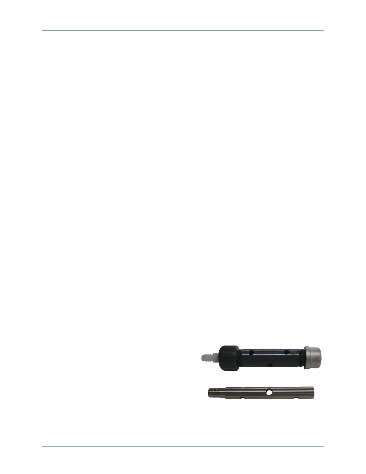
The far end of each tube is usually connected to
an in-stream strainer, such as the stainless steel or
PVC strainer available from QCEC. As shown to the
right, both of them feature barbed fittings that the
intake lines can be slipped over and clamped to.
⦸
The CVE-16 vacuum system cannot be used to sample pressurized wastewater streams, or
open streams whose surfaces are higher than the sampler. Attempting to do so will ruin
the sampler by filling it with water.
June 13, 2016 Revision 2A page 15
Century 3000 CVE-16 Wall-Mount Indoor Wastewater Sampler Installation
2.2: Positioning Considerations
Your CVE-16 Wall Mount Sampler can be installed in nearly any location, provided the wastewater stream from which the samples will be drawn is no more than 23 feet below the top of
the sampler’s housing (28 if equipped with the optional quick-lift pump).
The unit is equipped with a grounded 9-foot 14/3 AWG power cord that exits the upper right
side of the housing. If an AC receptacle is not located within reach of that cord, a sufficientlylong, customer-provided appliance-quality 15-amp extension cord will be needed.
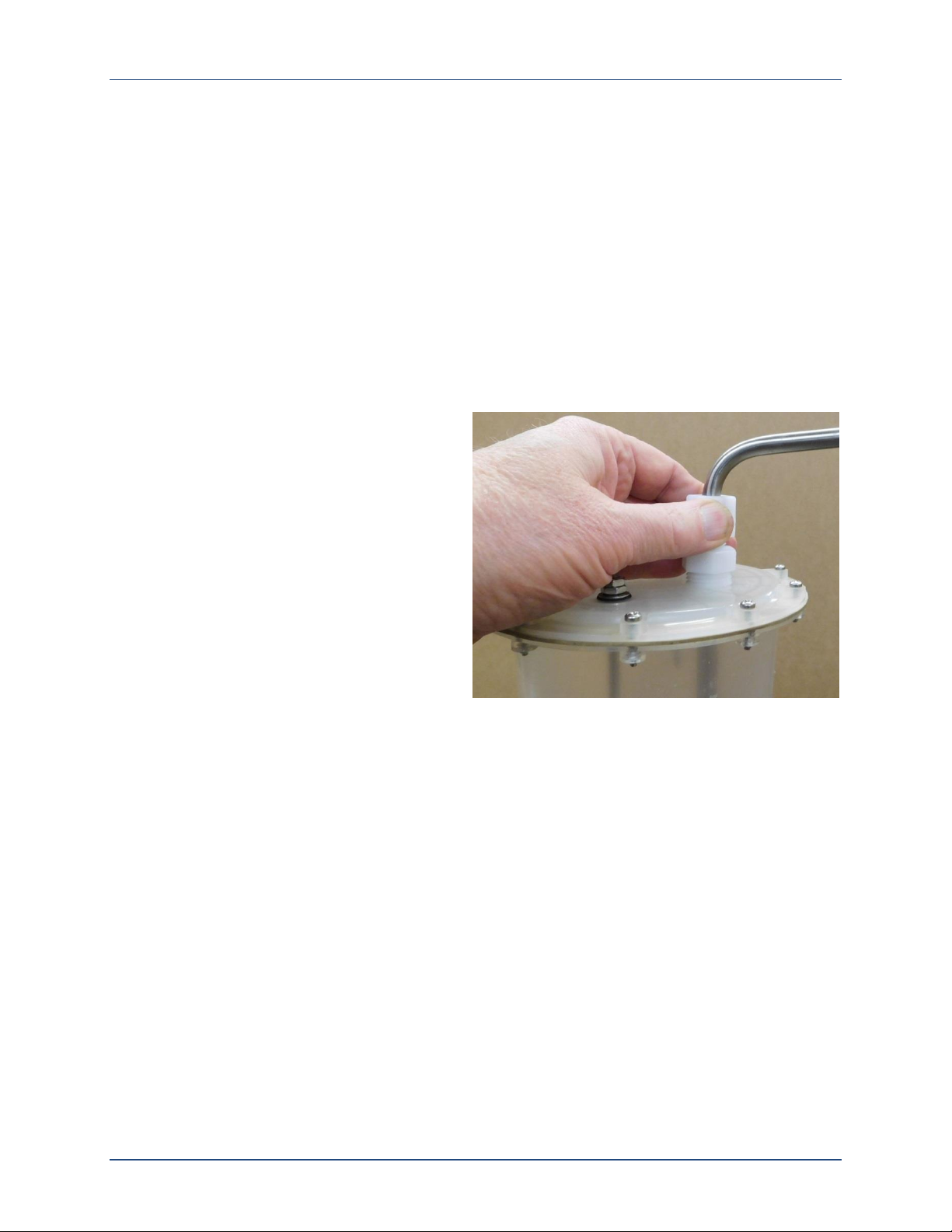
2.3: Sample Size Adjustment
The CVE-16 sampling system collects uniform samples by suctioning wastewater into a sample
chamber until it rises above the bottom of the intake tube, then blowing the excess back out.
The size of those samples can thus be changed by adjusting how far that tube extends below
the top of the sample chamber.
That tube extends down into the chamber
through a compression fitting mounted in its
lid. To adjust its extension into the chamber,
repeat the following steps until the desired
sample size is obtained:
4. Loosen the compression fitting nut.
5. Slide the tube farther down into or up
out of the chamber.
6. Retighten the compression fitting nut.
7. Draw a manual sample and measure its
volume.
✍
The sample size must be known to avoid setting the sampling programs to discharge more
wastewater to the sample containers than they can hold.
2.3.1: Velocity Valve Adjustment
In order to raise small samples limited distances, you might need to open the velocity-limiting
valve. For example, if you need to lift 100 milliliter samples less than three feet, you should
start by opening that valve two turns from its factory setting.
As shown on Figure 1-1, that valve is mounted to just to the right of the sample chamber:
To open that valve, thus reducing the vacuum force applied to the sample chamber and
the resulting water flow rate, turn the chrome knob counterclockwise.
To close it, thus increasing the vacuum and flow rate, turn that knob clockwise.
June 13, 2016 Revision 2A page 16
Century 3000 CVE-16 Wall-Mount Indoor Wastewater Sampler Installation
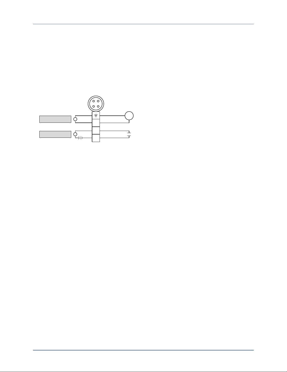
2
1
3
Analog Flow Signal
(4-20mA | 0-10VDC | 0-5VDC)
Pulsing Signal
(Dry Contacts)
FT
External
Connector
Analog Input
Pulse Input
~
+
˗
2.4: Field I/O Connections
CVE-16 Wall Mount Samplers can be equipped with either or both of the following circular
plastic connectors (CPC) for field I/O device cables:
a four-pin flow inputs connector (analog and/or pulsing-discrete signals)
a seven-pin field I/O connector (alarm and run output and float input signals)
Custom cables must be fabricated (from the provided matching screw-terminal cable connectors)
for any field devices you chose to connect.
Figure 2-1: Flow Input Connections
2.4.1: Flow Inputs
The four-pin flow input connector provides field wiring terminals for pulse and analog flow input
signals, either of which can be connected and used to trigger sample collection at configured
stream flow intervals (see page 80):
If that feature is configured for a pulsing input, connect a dry-contact signal source to
input connector pins 1 and 2. The interval pulse count will be incremented each time that
controller-powered circuit is externally closed.
✍
To adapt this input to an externally-powered discrete signal, connect it to the normallyopen contacts of an interposing relay and use that signal to energize the relay coil.
If that feature is configured for a 4-to-20 mA, 0-to-5 V or 0-to-10 V analog flow signal,
connect the transmitter’s positive (+) and negative (‒) terminals to input connector pins 3
and 4 (ground), respectively.
QCEC offers both an open-channel ultrasonic flowmeter (the QC-OC-1) and a closed-channel
Doppler flowmeter (the QC-DT-1), both of which provide both analog and pulsing discrete flow
outputs that satisfy the requirements of our wastewater sampler flow inputs.
June 13, 2016 Revision 2A page 17
Century 3000 CVE-16 Wall-Mount Indoor Wastewater Sampler Installation
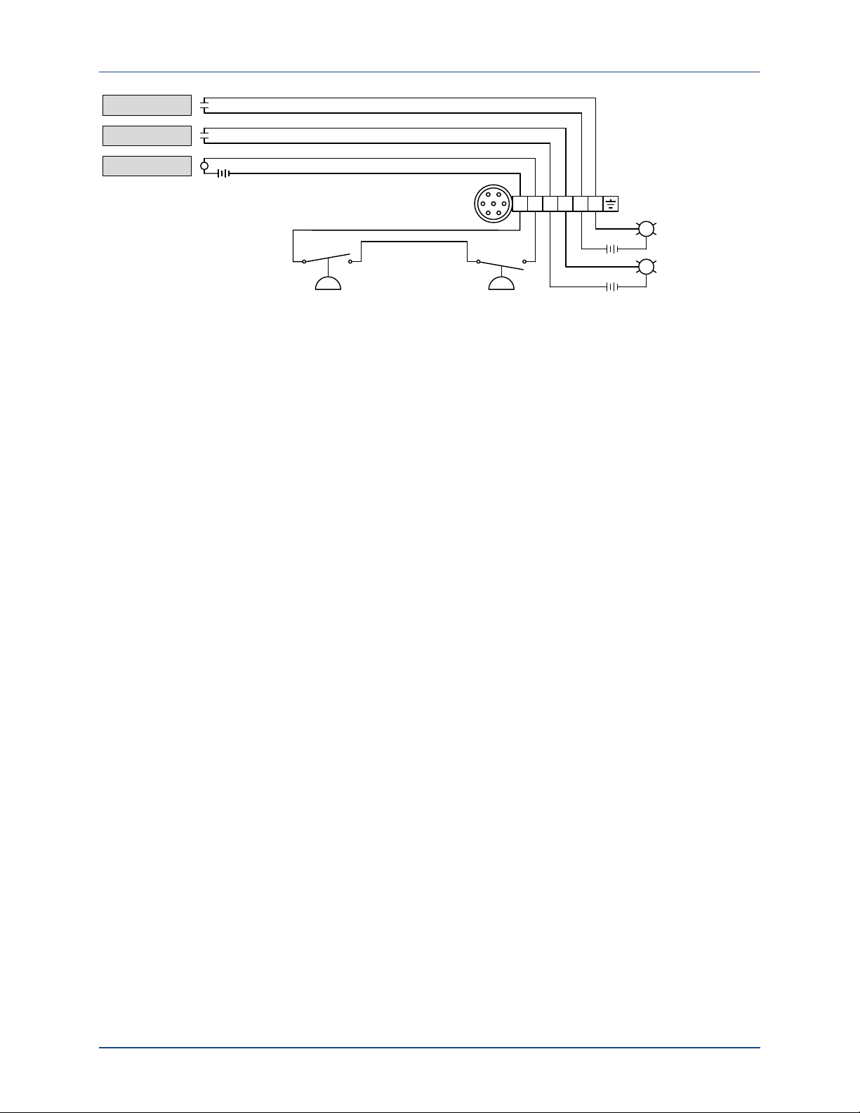
Bottle-Full
Float Switch
Run Relay
Alarm Relay
3 41 2 65
External
Connector
Stream-Level
Float Switch
Float Input
Run Monitor
Alarm Monitor
5A max.
5A max.
Figure 2-2: Relay Output and Float Input Connections
2.4.2: Relay Outputs
As shown above, four of the optional field I/O connector’s seven pins connect to 5 Amp relay
contacts on the controller’s power board:
the run-status relay connects pins 3 and 4 when the unit is sampling (see page 78)
the alarm relay (if enabled, see page 45) connects pins 5 and 6 when sampling is stopped
or certain non-fatal fault conditions are detected (see page 74).
They can thus be used to turn appropriate
on and off, or to signal those conditions to a SCADA or other host control system.
externally-powered
indicator lamps or annunciators
2.4.3: Float Input
The optional field I/O connector also provides a pair of terminals wired to the controller’s selfpowered Float Input (see page 76). No samples will be drawn unless that circuit is closed or
the Float Option (see page 45) is disabled:
If your unit was purchased with a composite sample container, it will include a bottle-full
float switch that will open as the fluid level rises above about 90 percent of the container’s
volume (if not, you can obtain a suitable container and float-switch from a third party). If
such a switch is wired across pins 1 and 2 of the field I/O connector, it will interrupt the
collection of samples before the sample container overflows.
Alternately, those I/O connector pins can be wired to a stream-level float switch (or other
dry-contact device) that closes the circuit only when the stream flow is sufficient to sample.
The sampler can then be configured to delay or interrupting the collection of samples if
there is not enough flow to sample.
✍
Due to the variety of suitable stream-level sensors that are available, QCEC neither sells
nor recommends them—you must select and obtain one from a third-party supplier.
To employ both a bottle-full and a low-flow float switch, wire them in series across pins 1
and 2 of the I/O connector (as shown above). Samples will then be drawn only when both
switches are closed.
If you do not want to install either type of float switch, you must either disable the Float
Option or install a jumper across I/O connector pins 1 and 2.
June 13, 2016 Revision 2A page 18
Century 3000 CVE-16 Wall-Mount Indoor Wastewater Sampler User Interface Panel
QCEC
4280 E. 14th Street • Des Moines, IA 50313
phone: 515-266-2268 • fax: 515-266-0243
www.qcec.com
F1
21 3
54 6
87 9
0
F2 F3
Back Enter
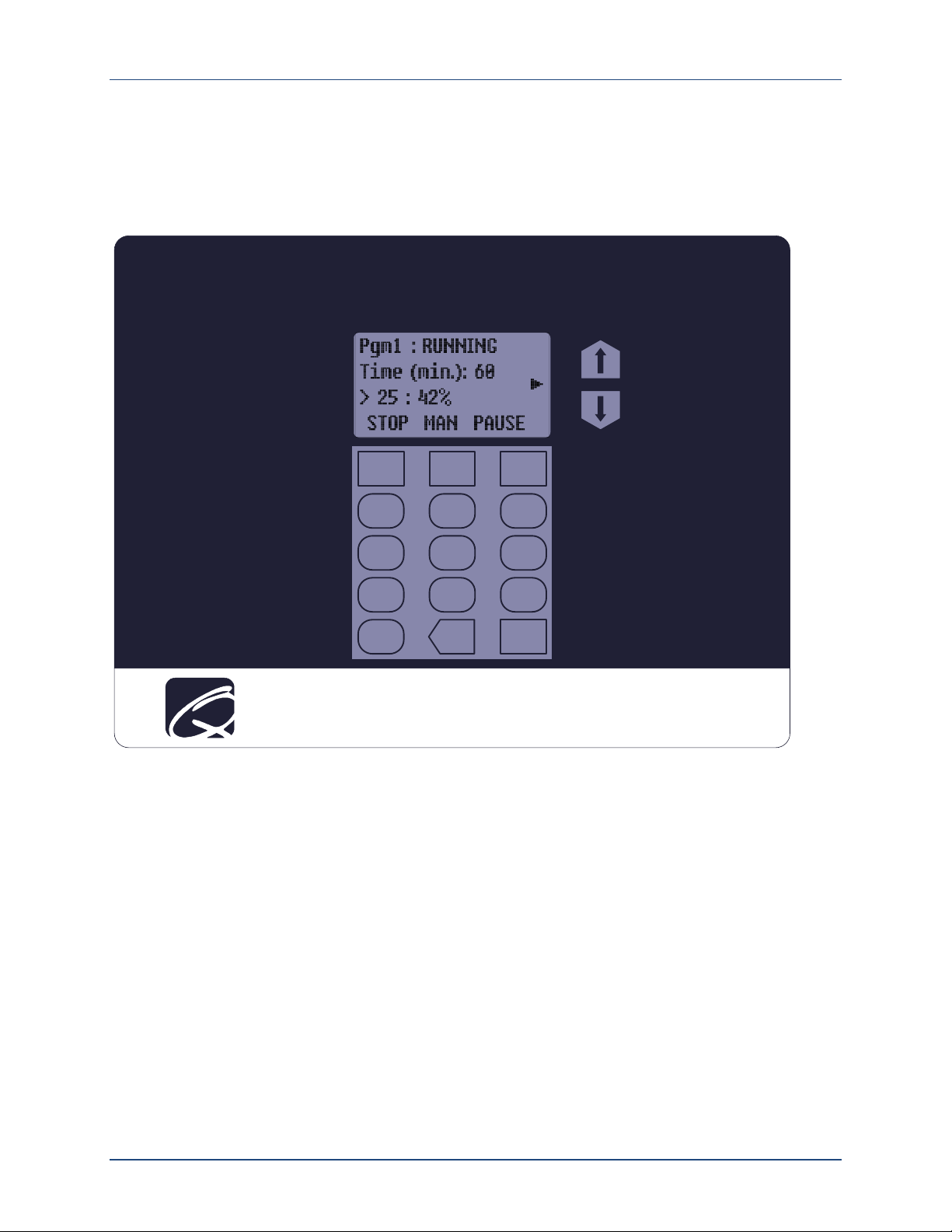
Chapter 3: User Interface Panel
The sampler’s operation can be configured, monitored and controlled using its user interface
panel, which consists of an LCD readout and password-protected keypad mounted behind the
clear access door.
Figure 3-1: User Interface Panel
Its LCD readout displays the identity of the selected sampling program, which the operator can
start and stop or pause and resume (see Chapter 5: Sampler Operation). It displays four lines
of alphanumeric text, plus a column of status icons that might appear along its right edge:
The top line identifies and displays that program’s operating state. The second and third
lines display sets of status information, which you can cycle through by pressing the UP
and Down keys to the right of the LCD.
The bottom line indicates the functions (if any) of the top three keys (F1, F2 and F3).
Various status icons (see Table 5-1 on page 53) are displayed along the right edge of the
readout (as you face it).
The display panel backlight will automatically turn off if no keyboard activity has been
detected in the last two minutes. Pressing any key will then turn it back on.
June 13, 2016 Revision 2A page 19
Century 3000 CVE-16 Wall-Mount Indoor Wastewater Sampler User Interface Panel
or
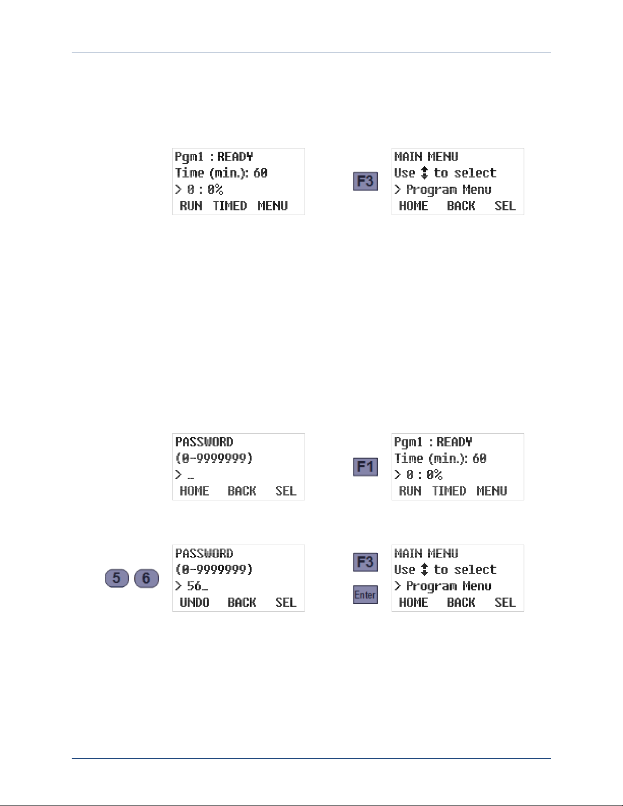
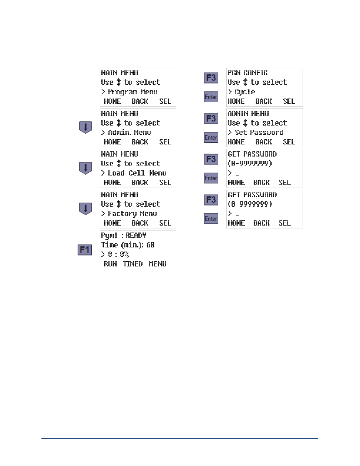
3.1: Menu System
The control system is set up and administered via a hierarchical menu (see page 72) accessed
by pressing the F3 key when the prompt above it reads “MENU”. If the administration password
(see page 22) has its default value (0), the first Main Menu option will then be displayed:
If that password has a non-zero value, the Password entry screen will appear instead. Like
many other menu screens, it assigns the HOME, BACK and SEL[ect] functions to the F1, F2 and
F3 keys:
Pressing HOME [F1] generally displays the parent menu for the current screen. If you are
editing settings, any changes you have made to the current parameter will not be saved.
Pressing BACK [F2] or the Back (bottom row, center) key generally restores the previously-
displayed screen or, if you are editing numerical parameter values, backspaces over the
most-recently typed digit.
Pressing SEL [F3] or the Enter (bottom row, right) key generally displays the next parameter
or screen in a sequence. If you are editing settings, any changes you have made to the
current parameter will be saved.
In this case, pressing HOME [F1] would restore the operating state display (as would BACK [F2]
or the Back key before you start typing the password):
To access the Main Menu, use the numeric keys to type the correct password, then press SEL
[F3] or the Enter key. If the password was 56, for example:
Typing the first digit changes the F1 prompt to UNDO—pressing that key would then clear any
digits you had typed so far and restore the initial Password screen. In contrast, pressing BACK
[F2] or the Back key will clear only the last typed digit.
June 13, 2016 Revision 2A page 20
Century 3000 CVE-16 Wall-Mount Indoor Wastewater Sampler User Interface Panel
or
or
or
or
Whenever any Main Menu screen is displayed, you can scroll through its four options by
pressing the Up or Down key, display the first option of the indicated subordinate menu by
pressing SEL [F3] or the Enter key, or exit the menu system by pressing HOME [F1]:
For convenience, each of those subordinate menus is set up so saving a setting (or initiating
an action) automatically displays the next one. Also, pressing the Enter key (or SEL [F3], if
available) when a setting’s current value is first displayed leaves it unchanged. So you can
advance through the entire menu, viewing but not changing any settings, by simply pressing the
Enter key enough times.
✍
Access to the Load Cell and Factory Menus, which are used to adapt each controller to
its sampler prior to shipment, are restricted by additional secret passwords.
June 13, 2016 Revision 2A page 21
Century 3000 CVE-16 Wall-Mount Indoor Wastewater Sampler User Interface Panel
or
3.2: Administration Menu
Administration Menu screens can be used to:
change or clear the administration password (see page 22),
set the real-time clock and enable/disable daylight savings time (see page 24),
adjust the LCD brightness (page 25),
download and erase the archived data (see page 26),
change the unit’s ID number (page 27), and/or
select English or Metric volumetric units (page 27).
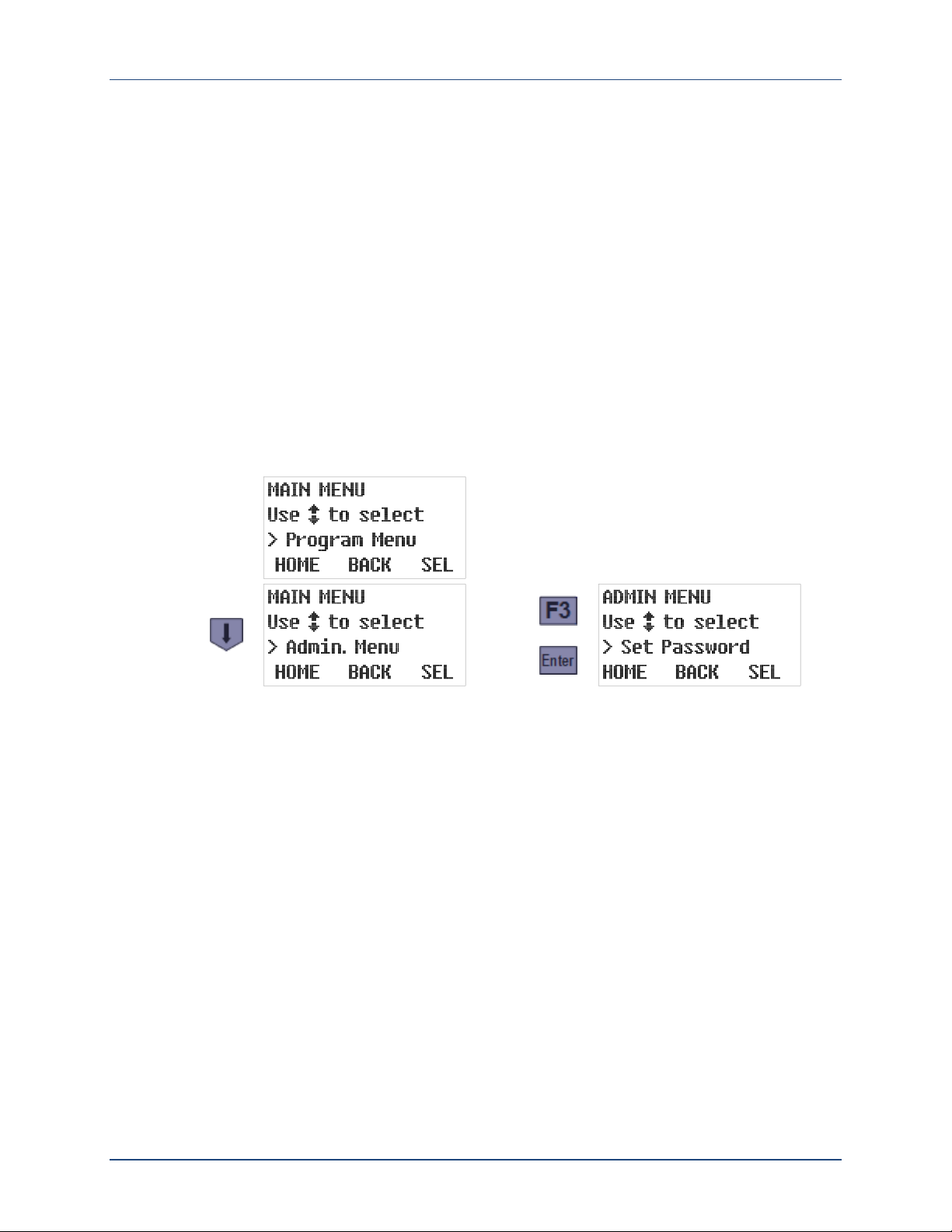
To access those features:
1. Access the Main Menu by pressing the MENU [F3] key and (if so prompted) entering the
optional password (see Menu System above).
2. Press the DOWN key to scroll to the Administration Menu option, then press the SEL [F3] or
Enter key to display that menu’s first option:
3.2.1: Administration Password
The administration password can be used to prevent unauthorized individuals from accessing
the Administration and Program menus (see page 20):
If it is set to zero (its factory default value), pressing the MENU [F3] key will immediately
display the first Main Menu option.
If it is assigned a value from 1 to 9,999,999 (leading zeroes are not allowed), pressing
MENU [F3] will display the Password entry screen.
✍
The Load Cell and Factory Menus, which are meant to be used only by QCEC personnel,
are protected by additional passwords that must be entered even if the administration
password is cleared (set to zero).
✍
If you forget the value of your administration password, contact QCEC for instructions on
how to regain access to your sampler’s menu system.
June 13, 2016 Revision 2A page 22
Century 3000 CVE-16 Wall-Mount Indoor Wastewater Sampler User Interface Panel
or
or
or
2 second
delay, then
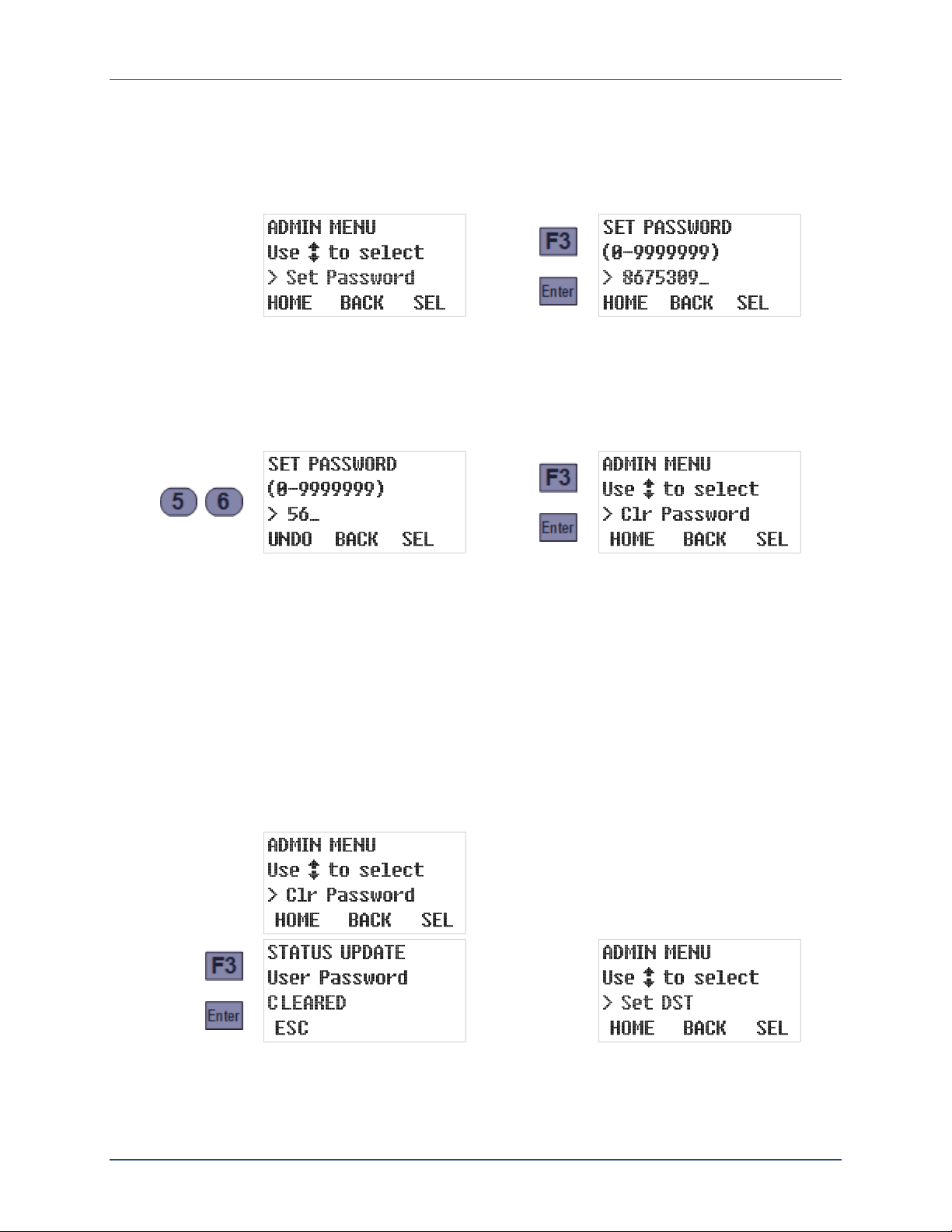
To change the administration password’s value:
1. Select the Administration menu (see page 22) to display its first option (Set Password). The
second line of the readout will then show the range of allowable values while the third
displays the current password:
2. Type the new password by pressing the corresponding numeric keys (the old password will
be erased and the F1 prompt will change from HOME to UNDO). Then press the SEL [F3] or
Enter key to save the displayed password and advance to the next Administration Menu
option. To change it to 56, for example, just press 5, then 6, and finally SEL [F3] or Enter.
The new value will then be saved and the next Admin Menu option will be displayed:
While entering a new password:
Pressing UNDO [F1] would restore the old password value.
Pressing BACK [F2] or the Back key would delete the right-most typed digit. Backspacing
over the first digit will restore the old password.
Setting the password to zero (0) removes any previously set Administration and Program Menu
protection. An easier way to do that, however, is to execute the second Admin Menu option:
1. Select the Administration Menu (see page 22 and press the DOWN key to display its Clear
Password option.
2. Press the SEL [F3] or Enter key to immediately set the password to zero. A STATUS
UPDATE screen will appear briefly, followed by the next Administration Menu option:
June 13, 2016 Revision 2A page 23
Century 3000 CVE-16 Wall-Mount Indoor Wastewater Sampler User Interface Panel
press
until you see
or
or
or
3.2.2: Clock Settings
The control board includes a real-time clock chip with a backup battery, so it runs even when
the control board is powered down. This enables it to timestamp all archived data and to
collect samples at scheduled times. In addition, the current time and date are displayed on the
third line of the second operating status screen (see page 58).
The third Administration Menu option allows you to quickly adjust the clock by one hour when
daylight savings time (DST) begins or ends, while the fourth allows you to directly reset the
clock to the current date and time. Because you should make sure the DST option is correct
before setting the time, those options should be executed in the order presented:
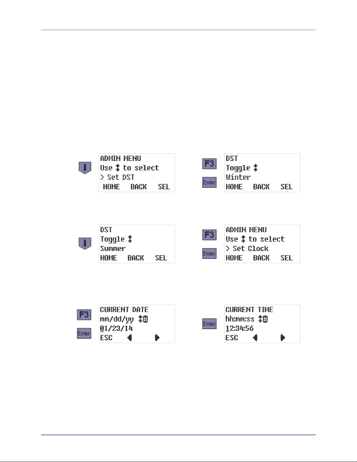
1. Select the Administration Menu (see page 22), use the Down key to scroll to its third (Set
DST) option, and then press the SEL [F3] or Enter key. The third line of the readout will
then show the current daylight savings time setting:
2. If necessary, press either the Up or the Down key to toggle that setting. When the desired
setting is displayed, press the SEL [F3] or Enter key to save it and display the Set Clock
option:
3. To adjust the date and time settings, press the SEL [F3] or Enter key. Otherwise, scroll to
another Administration Menu option or press the HOME [F1] key to restore the Main Menu.
The current date setting is displayed first. If it is correct, or after you have corrected it,
press the Enter key to save the displayed date and access the current time setting:
The same techniques are used to change both settings. The third line displays the current
value, with an underline cursor indicating the digit currently subject to editing:
Press the Previous [F2] or Next [F3] key to move that cursor one digit left or right.
Press any appropriate numeric key to set the current digit and advance the cursor, OR
press the Up or Down key to increment or decrement the current digit.
Press the ESC [F1] key to undo any change to the displayed setting and return to the
Administration Menu/Set Clock screen.
June 13, 2016 Revision 2A page 24
 Loading...