

Page 1

CEAombustionfficiencynalyzer
(US-Version,V3.1)
(US-Version,V3.1)
Page 2

16830ChestnutStreetCityofIndustry,
California91748,USA
TEL:626-934-1500
TOLLFREE:888-789-8168
FAX:626-934-1651
www.teledyne-ai.com
Page 3

Page 4

TableofContents
Page
1ProductDescription..................................2
2PhysicalData...........................................5
2.1CalculationFormulae..............................6
3TechnicalData.........................................7
4OperatingElement................................10
5KeypadFunctions..................................11
6UserGuide............................................12
6.1ProgramStartMenu..............................12
6.2CalibrationMenu...................................13
6.3FuelSelection.......................................14
6.4AdditionalFunctions/Meas.Program....15
6.5DraftMeasurement...............................16
6.6MenuLines............................................17
6.6.1MenuLine1...........................................18
6.6.1.1Menu-InfoBox.....................................19
6.6.1.2Menu-TimeandDate...........................20
6.6.2MenuLine2...........................................21
6.6.2.1Menu-.....................................21
Page
6.6.2.2Menu-CoreOfWasteGasFlow...........22
6.6.2.3COPurgeSystem()........22
6.6.3MenuLine3...........................................23
6.6.3.1Menu-Units..........................................23
6.6.3.2Menu-O2-Ref.......................................23
6.6.3.3Menu-Add.Data...................................24
6.6.4MenuLine4..........................................25
6.6.4.1MemoryFunctions.................................25
6.6.4.2Menu-Creatememoryblocks...............29
6.6.4.3Menu-Deletememorydata...................32
6.6.4.4PrintingtheMeasuredValues................34
6.7ConfigurationMenu...............................35
6.8EnteringtheCompanyAddress.............37
7SystemMaintenance.............................38
8RS232Interface....................................39
9Battery/LinePowerOperation...............39
10WiringDiagrams....................................42
11GasProcessing.....................................44Graphic
Menu- manual
1
Page 5

1.ProductDescription
TheGasAnalysisComputerisamultiple-functionanalyzerwithintegratedcalculatingfunctions.
MeasurementsareinaccordancewiththegeneralregulationssetforthbytheBIMSchV(German
Regulationsconcerningtheprotectionagainstharmfuleffectsontheenvironment)atallkindsof
combustionplantswithintheframeworkofthemonitoringofexhaustsystems.
a)Measurementandcalculationparameters
formonitoringexhaustsystemsandfordetermining
theefficiencyofcombustionplants:
MeasuredValues:T.GasWasteorfluegastemperature°For°C
T.RoomAirorambienttemperature
OOxygencontent%Volume
2
°For°C
COCarbonmonoxideppm-mg/m³-mg/kWh
NONitrogenmonoxide(Option)ppm-mg/m³-mg/kWh
DraftDraftorinchesofHO(iWC)
CalculatedValues:COCarbondioxide%Volume
2
Pressure
CO0%Carbonmonoxide,undilutedppm
Effi.Combustionefficiency%
Ex.airExcessairvalue
LossesWastegaslosses%
NOxNitrogenoxides(optional)ppm-mg/m³-mg/kWh
T.DiffDifferentialtemperature(TG-TA)
°For°C
2
2
Page 6

b)MeasuringProcedure
TemperatureMeasurem.:K-typethermocouple()forwasteorfluegastemperature
K-typethermocouple(NiCr-Ni)
O-Measurement:Electrochemicalmeasuringcell.
2
NiCr-Ni
forairorambienttemperature.
CO-Measurement:Electrochemicalmeasuringcell.
DraftMeasurement:Piezo-resistiveprinciplewithinternaltemperaturecompensation.
MeasuringDuration:Short-termmemorymeasurementsofmax.60minutesarepossible,followedby
anewcalibrationphasewithambientair.
WasteGasMeasurement:Viaanexternalwaterseparatorandfilter,thewastegasisfedtothesensorsby
meansofagasfeedpump.Thepumpcapacity duringthefeedingphaseis
approx.0.8l/min.
SensorCalibration:60secondsafterswitchingontheinstrument.
COConcentration:COsensorwithHcompensation,measuringrange0-4.000ppm.Cutoff
2
thresholdat4.000ppmforsensorprotectionviaseparateflushpump.
Theremainingmeasuringvaluesarenotaffected.Theinstrumentisswitchedon
againatavalueof1.600ppm.
WasteGasSampling:Bymeansofawastegassamplingprobewithretainercone.
3
Page 7

c)InstrumentDescription
ElectricalSupply:NiCadbattery6V/1200mAh,externalcharger.
Display:Withbacklight;alphanumericandgraphicdisplay.
4linesof16characterseach,plusmenuline.
ComputerInterface:RS232.
PrinterInterface:Infrared(HPProtocol).
Printer:Externalinfraredthermo-paperprinter.
Memory:100memoryblocks
Adm.OperatingTemp.:+40°Fto+104°F(+5°Cto+40°C).
Adm.StorageTemp.:-22°Fto+140°F(-30°Cto+50°C).
Mech.Dimensions:9.5”x3.6”x2.4”(242x91x61.5mm).
Weight:1.5lbs(700g).
StandardVersion:Instrument,batterycharger,combinedfluegastemperature
probe/watertrapandhoseassemblywithmeasuringcone,
ambientairtemperaturesensor,carryingcaseandmanual.
4
Page 8

2.PhysicalData
Measuringranges:CO0...4.000ppm
(GeneralSpecifications)
CO-0%0...9.999ppm
O0...20,9%Volume
2
T-Gas+32°Fto+1.850°F(0°C...+1.000°C)
T-Air-5°Fto+212°F(-20°C...+100°C)
Draft/Pressure(150.0hPa)
CO0,0...COmax%Volume
22
±±60inchesofHO
Losses0...100%
Efficiency100...0%
Excessair1...99.999.
Optional:NOx,NO0...2.000ppm
COHigh0...1.0%Volume(10.000ppm)
2
5
Page 9

2.1CalculationFormulae
O
2
CalculationoftheCOvalue:
CO:max.CO-value(fuel-specific)in%Volume.
2max
O:Measuredoxygencontentin%Volume.
2
2
2
21:Oxygencontentoftheairin%Volume.
Calculationofthewastegasloss:in%
T.Gas:Waste/fluegastemperaturein°For°C.
T.Room:Combustion/ambienttemperaturein°For°C.
A2,B:Fuel-specificfactors.
CO
2
=CO*(1--------)2max in%Volume
20.9
A2
qA=(T.Gas-T.Air)*(----------+B)
21-O
2
CO
2
max
Calculationoftheexcessairvalue(Lambda):
Calculationofthecombustionefficiencyvalue(Eta):in%
CalculationofCO0%(undiluted):inppm
Lambda=
------------=-----------CO20.9-O
2
Eta=100-qA
CO0%=CO*Lambda
20.9
2
6
Page 10

3.TechnicalData
WasteorFlueGasTemperatureMeasurement
Sensor:K-typethermocouple
Range:+32°Fto1.850°F(0to+1.000°C)
Resolution:0.1°For°C
Accuracy:1°C(0to+400°C)
CombustionAirorAmbientTemperatureMeasurement
Sensor:K-typethermocouple
Range:-5°Fto+212°F(-20to+100°C)
Resolution:0.1°For°C
Accuracy:1°C(0to+100°C)
±2°±
F/
0.5%ofreading(upto1.000°C)
±
F/
±2°±
F/
±6°±3
°C(-20.0to0.0°C)
DraftorPressure
Measurement
Sensor:Piezoresistivepressuresensor
Range:
Resolution:0.01orhPa
Accuracy:0.088.0or
±60 in.HOor2
in.HO
2
in.HOorin.HO
±±±±
1%ofreading
±±±
3%ofin.HO
±±±
reading(above80.0or20.0hPa)
150hPa
±
22
0.02hPa(upto2.00hPa)
(upto80.0or20.0hPa)
in.HO
2
2
7
Page 11

Oxygen(O)Measurement
2
Range:0to20.9%Volume
Accuracy:0.2
±
%Volume
Resolution:0.1%Volume
Sensor:Electro-chemicalcell
Responsetime(T97):70sec
<
Carbondioxide(CO
CalculatedfromOmeasurement
Range:
Accuracy:0.2%Volume
Resolution:
2
)Calculation
2
0toCOmax.
2
±
0.1%Volume
Responsetime(T97):<70sec
Carbonmonoxide(CO)Measurement(withHcompensation)
Range:
Accuracy:5ppm(upto150ppm)
2
0to4.000ppm
±
5%ofreading(upto4.000ppm)
±
Resolution:1ppm
Sensor:Electro-chemicalcell
Responsetime(T90):<60sec
8
Page 12

Options
Nitrogenmonoxide(NO)Measurement
Range:0to2.000ppm
Accuracy:5ppm(upto150ppm)
Resolution:1ppm
Sensor:Electro-chemicalcell
Responsetime(T90):<60sec
COMeasurement(withoutH2compensation)
Range:0...1.0%Volume(10.000ppm)
Resolution:0.01%Volume
Sensor:Electro-chemicalcell
Responsetime(T90):<60sec
±
5%ofreading(upto2.000ppm)
±
9
Page 13
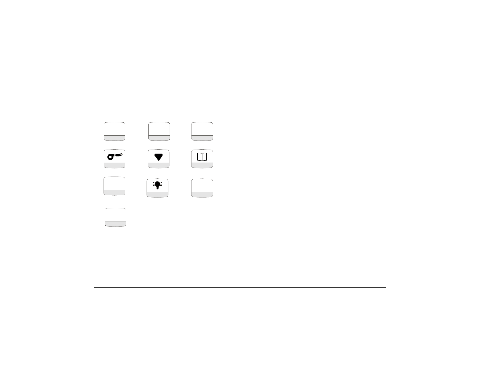
4OperatingElements
S1
START
STOP
0/I
S2
ENTER
ENTER
S3
mbar
hPa
10
Page 14

11
Page 15

Note:Thebatterystatusis
determinedbyhowmanybattery
symbolsthataredark.
7darksymbols=70%ofbattery
powercapacity
12
Page 16

Note:Donotplaceprobe-Leaveinambientair
untiltheunitisfinishedwiththecalibrationphase.
Note:Anyerrorsthatoccurduringcalibrationare
displayedontheinformationline.
Batt:
LowBatt
Battempty
T-RoomSensor?
T-GasSensor?
O2Sensordefect
O2Sens.Service
CO-Sensor?
CO-Sensordefect
CO-val.overflow
NO
-Sensor?
NO-Sensordefect
NO-val.Overflow
13
Page 17

NaturalGas
14
Page 18

15
Page 19

Attention:
NopressurevaluesExceeding
(150hPambar)!
±
Beforepressingthembar/hPakey,
pulltheairtubeofftheinstrument!
Thedraftsensoriscalibrated
(0.00InWorhPa).
±60inchesofHO2
Note:
FordraftMeasurement,connectairtubetothepositive(+)
connectoronly.
Carefullyreplacetheairtube.
Waituntilthemeasuredvaluehas
stabilized.
Recordthemeasureddraftvalue.
Thisvalueisstoredwiththecurrent
measuringvalues.
Themeasuringmodeiscontinued.
16
Page 20

Themenulinemakesitpossibleto
operatetheinstrumentinafastand
easyway.Pressingtheappropriate
softkey(S1toS3)accesses
submenudirectlyand/orallows
directexecutionofafunction.
17
Page 21

Or
Note:TheinformationBoxdisplaysthecurrentstatusof
battery,theselectedfueltype(includingCO2maxvalue)
andtheO2referencevalueforconvertingunits.
Therecordedmeasuredvaluesare
displayedininverseletters.
18
Page 22

O2Sensor75%
COSensor0%
H2Sensor0%
NOSensor0%
MomentarySensorfailureordegradingcanbesolvedbylonger
flushperiodsinambientairor/andbyexchangingthefilterelements.
Ifthefailureordegradingkeepsoccuringandcannotbefixed,
pleasecontactthesupplier!
SensorStatus:
O2reading:>50%
O2SensorOK
CO&H2reading:0to+1%
COSensorOK
NOreading:0to+1%
NOSensorOK
19
Page 23

Cursorflashes:OKtokeyin
yourentry.
20
Page 24

Intermediatestorageofthegraphics
andallmeasuredvalues.
21
Page 25

Themenu:'Max.Draft’providesagraphic
displayofsuchtendenciesasrisingorfalling
temperatures,whichareindicatedby
oscillationsofthebargraph.Assoonasthe
temperaturehasstabilizedthebargraph
appearsinthecenterofthedisplay.
Note:Ifnecessary,intermediatestorageof
measuredvaluesispossibleasfollows:
Allmeasuredvaluewillbestoredin
theintermediatestorage.
Whentheover-rangevalueof4.000
ppmhasbeenreachedtheCOflush
pumpisswitchedonautomatically.
22
Page 26

ABCabc
0123 /-+.
23
Page 27

Theselectedoptionisshownina
frame.
Aflashingcursorappearsatthefirst
entryposition.
Selectbetweenandforoil
derivatives.
YesNo
24
Page 28

NoFiles
areexistend
25
Page 29

Createsamemoryblockwithadditionaldata(e.g.
typeofcombustionplant,customeraddressetc.)
seeSection6.6.4.2,page29.
Page 30

27
Page 31

28
Page 32

0123 /-+.
Togglesbetween
figuresandspecialcharacters
Availablecharactersfor(customer)
code:
Figures:0to9
Specialcharacters:-+.,:*></
Youcanenterupto13consecutive
charactersintothe(customer)
codeline.
Page 33

ABC abc
0123 /-+.
Togglesbetweencapitalizationand
smallletters.
Togglesbetweenfiguresandspecial
characters.
Availableselectionofcharacters:
Letters:atoz,ä,ö,ü,ß
Letters:AtoZ,Ä,Ö.Ü
Figures:0to9
Special
characters-+.,:*></:
Upto16characterscanbeentered
consecutively.
30
Page 34

Uptofourlinesofcustomerdatacanbeentered.
Thememoryblockissavedforlatermeasurementsoruntilitis
deletedagain.
Storedvaluescanbeviewedbymeansofmenupoint'Display
Newmeasuredvaluescanbestoredinthememoryblockby
meanmeansofmenupoint'Save'.
31
Page 35

32
Page 36

Attention:Allmemoriesinlcudingadditionaldatawillbedeleted!
33
Page 37

Note:
Fordatatransferfromthemanualinstrumenttotheassociated
IRprinter,directthetopsurfaceoftheanalyzertowardsthe
printer.Themeasuringprotocolisprinted.
Pleasekeepaminimumdistanceo1”
(Maximumdistanceapproximately3”)
Attention:Infraredoptical
transmissionlink-always
keepstraightandfreefrom
obstacles!
34
Page 38

Adjustabledisplayillumination
from0-90seconds
inincrementsof5seconds.
35
Page 39

Attention:ConfirmingResetwithENTERcancelsall
instrumentsettings.Allmemoryblocksaredeleted.
36
Page 40

Entryofletters,figuresandspecialcharacters
asinthememorymode(Section6.6.4.2).
Theenteredorcorrectedcompany
addressisnowsaved
andwillalwaysappearonthe
printoutofmeasuringdata.
37
Page 41

7.SystemMaintenance
GasProcessing:
Attention:Emptythecondensatereservoircompletelyaftereachmeasuring
Plug-typeelements
andflanges:
Storage:
Seedrawingonpage44.
operation.Waterresidueswithinthemeasuringinstrumentwilldestroythe
pumpsandsensors!
Damageofthefilterand/orimproperlyfittedfilterwillgreatlydecreaseo
eliminatethefilterfunctionandwilleventuallydestroypumpsandsensors.
Checkthemicrofilterforcontaminationsandreplaceasnecessary.
Ifthepumpcapacityisreduced,exchangethediaphragmfilter.
Makesurethatthreadedpartsarestraightwhenplacedonandtightenthem
moderately.EnsuresufficientsealingbymeansofO-rings.
Removeanygasresidues.GreasewithVaseline.
Storeinacoolanddryenvironmentatatemperatureofapprox.60°F(20°C).
38
Page 42

Damages:
Guaranteeandwarrantyobligationsdonotapplytodamages
causedbyimproperhandling,negligenceandgraveexternal
influences.
8.RS-232Interface
ProvidesconnectionsforspecialServiceandDataCommunications.
9.Battery/LineVoltageOperation
Batteryoperation:
Batterycharger:
Statusdisplayofthe
storagebattery:
Maximum8hoursofcontinuousmeasuring.
Externalcharger110V~/60Hz.
Intelligentmonitoringbymeansofinstrument-integratedmicrocontroller
TomaintaintheservicelifeandperformanceoftheNiCadbattery,please
observetheinstructionsunder'Informationonchargingthebattery'.
Shownonthebottomlineofthedisplayduringthecalibrationphase.
Duringthemeasurement,thestatusofthebatterycanberead
The'Info'Menu.
from
39
Page 43

InformationonChargingtheBattery
CEA9001isequippedwithanNiCadstoragebattery.Theservicelifeandcapacityofthebatteryareconsiderably
affectedbythewaytheinstrumentischargedandused.Inordertomakethehandlingsafer,theinstrumenthasa
loadmanagementunit.
IfanNiCadbatteryis,forexample,alwayschargedfrom80%to100%andneverrundowntothefinaldischarge
voltage,itwilllosesomeofitscapacity.Thisiscalledthe'memoryeffect',i.e.thebatteryrememberstowhat
extentitisrundown.
Apartofthismemoryeffectissuppressedintheinthatthebatterycannotberechargeduntilithas
droppedbelow60%.
Constantovercharging,too,hasadverseeffectsontheNiCadbattery.Inordertopreventthis,thecharged
capacity,thevoltageandthetemperatureofthebatteryaremonitoredinthe.Whenpredefinedlimits
areexceeded,thechargingprocessisinterrupted.Aftertheappropriateparametershavebeenneutralizedthe
chargingprocessisautomaticallyrestartedagain.
TheservicelifeoftheNiCadbatterycanbesignificantlyreducedwhentheinstrumentisoperatedat
temperaturesbelow40°F(5°C).
Thegraphiccharge-levelindicatorofthe(10batterysymbols),whichappearsintheone-linestatus
displayduringthecalibrationphase,helpstheuserestimatecorrectlythecapacityofthebattery.Theinstrument
continuouslymeasurestheincomingandoutgoingcurrentduringoperationandcharging.Undernormal
operatingconditions,theinstrumentshouldbeoperateduntilthebatteryiscompletelyrundown.Whenthis
adviceisfollowed,theactualcapacityoftheNiCadbatterywilldefinitelybeshownonthedisplay.
CEA9001
CEA9001
CEA9001
40
Page 44

StoringtheinstrumentisonlyrecommendediftheNiCadbatteryisfullycharged.Iftheinstrumenthastobe
storedforaprolongedtime(approx.2weeksorlonger)itisrecommendedtoleavetheinstrumentconnectedto
thecharger.Thesameappliestolow-leveldischargeofthebattery:leavetheinstrumentconnectedtothe
chargerforalongerperiod(upto12hours).
Iftheinstrumentisoperatedattemperaturesexceedingtheadmissibletemperaturerange,iftheNiCadbatteryis
older,orifincompletechargingcycles(charging/discharging)areperformed,itispossiblethatthedisplayno
longercorrespondstothecurrentstatusofthebattery.
Inthiscasethedisplayiscorrectedasfollows:dischargethebatterybyswitchingonuntiltheinstrumentswitches
offautomatically.Afterthat,connecttheinstrumenttotheassociatedchargerandwaituntiltheendofthe
chargingperiod(max.4hours).Whenthechargingprocessiscompleted,theswitchesoff
automatically.
UsedorDeadBattery
ForreplacementofaUsedorDeadbattery,theanalyzerhastosentbacktothesupplier/manufacturer.
CEA9001
41
Page 45

42
Page 46

43
Page 47

PartNo 20591
ø23.5mmHydrophobFilter
Gratingstructuremustbe
directedoutward!
PartNo 20921
GASPROCESSING (PartNo.VK-00190)
O-Ring18x3
PartNo20365
PartNo 20592
O-Ring23x2
PartNo 20370
Microfilter
PartNo.20919
O-Ring23x2
O-Ring23x2
PartNo20370
PartNo 21990
O-Ring23x2
PartNo 20370
Maintenance
PartNo 21778 PartNo20596
O-Ring23x2
PartNo 20370
PartNo20594
44
 Loading...