

Page 1
CANbus Trigger, Decode, and
Measure
Software Option
Operator's Manual
December, 2008
Page 2
Manufactured under an ISO
9000 Registered Quality
Management System.
Visit www.lecroy.com to view
the certificate.
This electronic product is subject to disposal and
recycling regulations that vary by country and region.
Many countries prohibit the disposal of waste
electronic equipment in standard waste receptacles.
For more information about proper disposal and
recycling of your LeCroy product, please visit
www.lecroy.com/recycle.
LeCroy Corporation
700 Chestnut Ridge Road
Chestnut Ridge, NY, 10977-6499
Tel: (845) 578-6020, Fax: (845) 578 5985
Warranty
LeCroy warrants this oscilloscope accessory for normal use and operation within specification for a period of one year
from the date of shipment. Spare parts, replacement parts and repairs are warranted for 90 days.
In exercising its warranty, LeCroy, at its option, will either repair or replace any assembly returned within its warranty
period to the Customer Service Department or an authorized service center. However, this will be done only if the
product is determined by LeCroy’s examination to be defective due to workmanship or materials, and the defect is not
caused by misuse, neglect, accident, abnormal conditions of operation, or damage resulting from attempted repair or
modifications by a non-authorized service facility.
The customer will be responsible for the transportation and insurance charges for the return of products to the service
facility. LeCroy will return all products under warranty with transportation charges prepaid.
This warranty replaces all other warranties, expressed or implied, including but not limited to any implied warranty of
merchantability, fitness or adequacy for any particular purposes or use. LeCroy shall not be liable for any special,
incidental, or consequential damages, whether in contract or otherwise.
Internet: www.lecroy.com
© 2008 by LeCroy Corporation. All rights reserved.
LeCroy, ActiveDSO, JitterTrack, WavePro, WaveMaster, WaveSurfer, WaveLink, WaveExpert, Waverunner, and WaveAce
are registered trademarks of LeCroy Corporation. Other product or brand names are trademarks or requested trademarks
of their respective holders. Information in this publication supersedes all earlier versions. Specifications are subject to
change without notice.
CANbus-TD-TDM-OM-E RevB
916940-00 RevA
Page 3

Operator's Manual
CANbus-TD-TDM-OM-E RevB
iii
TABLE OF CONTENTS
Introduction ............................................................................................................. 5
Overview ...................................................................................................................... 5
Compatibility................................................................................................................ 6
Assumptions ................................................................................................................ 6
The TD Series Software ............................................................................................. 6
The TDM Series Software .......................................................................................... 7
Using the CANbus Options ........................................................................................ 9
Accessing Serial Triggers .............................................................................................. 9
Creating a CANbus Trigger Condition ........................................................................ 10
CANbus Trigger Setup Detail...................................................................................... 10
CANbus Decode Setup Detail ..................................................................................... 14
Measuring CANbus Performance Using CANBUS TDM .............................................. 15
Overview of CANbus TDM (Trigger, Decode, Measure/Graph) ................................. 15
CANBUS TDM Parameters ......................................................................................... 16
CANbus TDM Graphing and Statistical Analysis ........................................................ 17
General Setup of CANbus TDM Parameters .............................................................. 18
CAN-to-Analog or Analog-to-CAN Measurement Parameter .................................... 22
CAN Message-to-CAN Message Measurement Parameter ....................................... 25
Extract CAN Message Data to a Decimal Value ......................................................... 27
CAN Bus Message Load Percent Measurement Parameter ...................................... 28
Time from Trigger Point to CAN Message Parameter ............................................... 30
Characterizing CANbus System Performance ............................................................ 30
System Performance Characterization Overview ...................................................... 30
Using Cursors ............................................................................................................. 32
Using Measurement Parameters ............................................................................... 34
Measurement Gating ................................................................................................. 35
Using Statistics and Graphing .................................................................................... 35
Pass/Fail Analysis with Measurement Parameters.................................................... 36
Page 4

CANbus Trigger, Decode, and Measure
iv
CANbus-TD-TDM-OM-E RevB
Isolating and Analyzing CANbus Activity .................................................................. 37
Isolate and Analyze Serial Bus Activity ...................................................................... 37
Reference ............................................................................................................... 45
CANbus TD and TDM Specifications .......................................................................... 45
Safety Requirements ................................................................................................. 47
Appendix A: External Trigger Hardware ................................................................... 48
CANbus TD Standard Hardware ................................................................................. 48
Accessories ................................................................................................................ 51
Connecting to a CANbus Circuit ................................................................................. 51
Trigger Setup .............................................................................................................. 62
Page 5

Operator's Manual
CANbus-TD-TDM-OM-E RevB
5
Introduction
Several communication protocol types are used in automotive applications. They are used to
send data from sensors to electronic control units (ECUs) or from one ECU to another. These
protocol types include Controller Area Network (CAN), Local Interconnect Network (LIN), and
FlexRay. LIN is a low-cost master/slave system designed for low-cost implementation in vehicles,
typically in what is commonly referred to as body electronics. FlexRay is a time-triggered
automotive communications bus designed for higher speeds and fault tolerance.
This manual focuses on the CANbus TDM and TD products. LeCroy also has separate LIN and
FlexRay products and manuals.
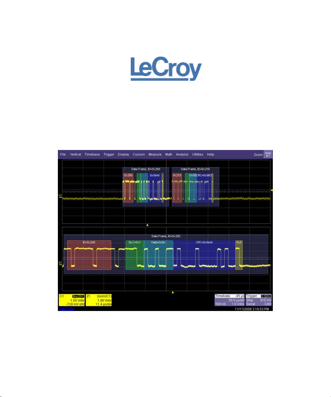
Overview
CANbus TDM and TD options contain powerful software algorithms which extract serial data
information from physical layer waveforms measured on your oscilloscope. The extracted
information is overlaid (annotated) on the actual physical layer waveforms, and color-coded to
provide fast, intuitive understanding.
The CANbus TD option allows triggering on CAN Frames and Errors. Frame triggering can be set
to trigger on any frame, one specific Frame ID, a range of Frame IDs, Remote Frames, and Errors.
Frame triggering and data triggering can be done for a single ID or message or a range of IDs and
data by using the conditional trigger capabilities. Other powerful and user-friendly features
included in CANbus TD include:
The ability to trigger and decode CAN at bit rates from 10 kb/s to 1 Mb/s.
The ability to create powerful, conditional Frame ID and Data triggers.
Triggering on CAN protocol errors and remote frames.
If you are unfamiliar or are just learning about CAN, start by using the simplest trigger conditions
(All Frames or Frame ID). Next, experiment with an ID and Data to trigger on a specific value.
Then, try a conditional ID + Data trigger (ID Greater Than or In Range).
The CANbus TDM and TD Serial Data options are unique oscilloscope tools from LeCroy which
greatly increase your ability to debug and analyze embedded controllers that use CAN. The TDM
product include Serial Trigger, Decode and Measure/Graph capabilities, the TD product include
Serial Trigger and Decode.
The CAN trigger is integrated into the oscilloscope - meaning no external hardware is used. It's
selected through the normal oscilloscope trigger menus. CAN signals are sent to the oscilloscope
using a differential probe like the ADP305 or AP033. Decoding is accessed from the Analysis
menu. The decoding is overlaid on top of the appropriate channel, and is intuitively presented
and color-coded for quick understanding. Measurement and graphing capabilities may be
accessed through the Measure/Graph tab in the Decode Setup or from the Measure menu. All
Page 6

CANbus Trigger, Decode, and Measure
6
CANbus-TD-TDM-OM-E RevB
packages contain Search capability for specific IDs, Data and Errors and a Table displays
summarized protocol data underneath the oscilloscope grid.
Compatibility
The CANbus TDM option is compatible for WavePro Zi and WaveRunner Xi oscilloscopes. The
CANbus TD option is compatible with the WavePro Zi, WaveRunner Xi and WaveSurfer Xs
oscilloscopes. CAN triggering is completely integrated with the oscilloscope and no external
hardware is required. Earlier versions of LeCroy’s CANbus TDM and TD options required the use
of an external trigger module, for documentation ion how to use the external trigger module
please see the appendix. The external trigger module is still available for use with WaveMaster
8000A, WavePro 7000A, and WaveRunner 6000A oscilloscopes.
Note: All references to Decode and Measure/Graph capabilities and functionality are identical
whether the external or internal CAN trigger is being used.
Assumptions
This manual assumes a basic understanding of the FlexRay standard physical layer and protocol
layer specifications, and knowledge of how FlexRay is used. Also, a basic understanding of
oscilloscope operation - specifically the LeCroy oscilloscope which the FlexRay trigger, decode,
and physical layer option is used with - is assumed. Wherever practical or necessary, details on
specific oscilloscope features have been included in this manual.
Note: LeCroy has a policy of frequently updating software. While screen images in this manual
may not exactly match what is seen on your oscilloscope display, be assured that the
functionality is nearly identical.
The TD Series Software
The TD option adds the following capability to the LeCroy oscilloscope software user interface
dialogs:
1. Serial Trigger Selection - If this is the first serial trigger option you have installed on your
oscilloscope, an additional icon is shown on your trigger dialog box. It allows a serial
trigger condition to be set from within the oscilloscope using an easy-to-understand
interface.
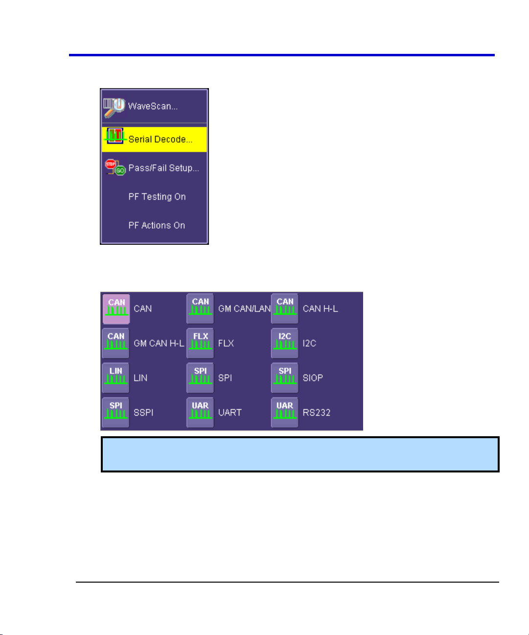
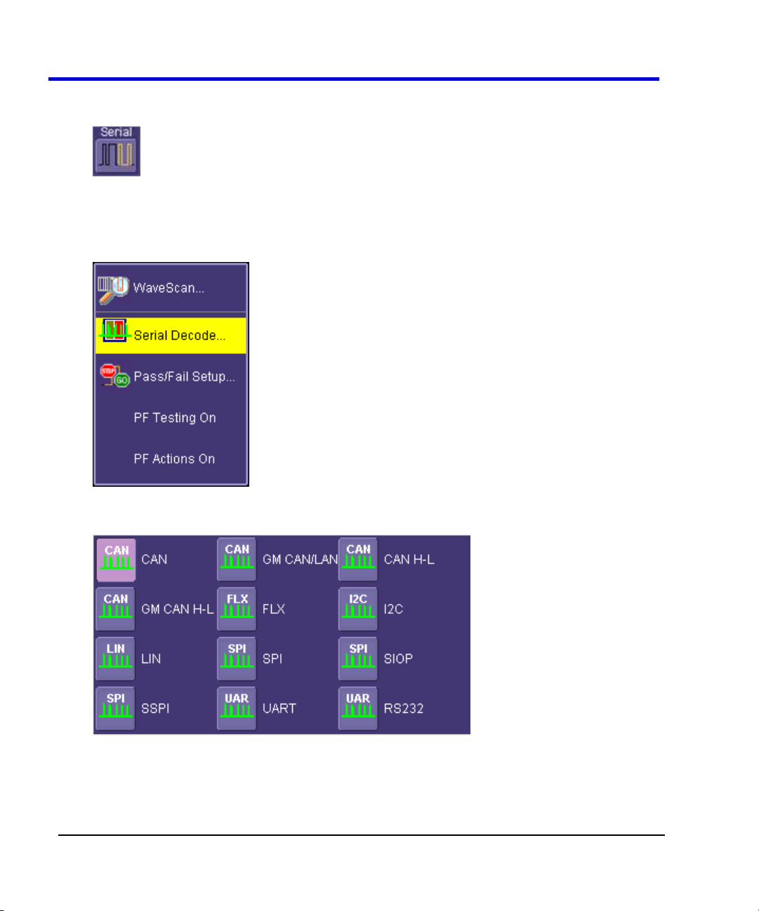
2. Serial Decode - If this is the first serial decode option you have installed on your scope, an
additional set of Serial Decode and Decode Setup dialog boxes are provided for setup of
Page 7
Operator's Manual
CANbus-TD-TDM-OM-E RevB
7
protocol format (as necessary) and decoding. These can be accessed from the Analysis
menu.
3. Decode Protocol Selections - As serial decode options are added to your oscilloscope,
additional protocol selections are available in a pop-up dialog box within the Serial
Decode dialog boxes.
Note: SIOP and SSPI are part of the SPIbus TD package. RS232 is part of the UARTRS232bus TD package.
The TDM Series Software
The TDP option adds the following capability to the LeCroy oscilloscope software user interface
dialogs:
1. Serial Trigger Selection - If this is the first serial trigger option you have installed on your
oscilloscope, an additional icon is shown on your trigger dialog box. It allows a serial
Page 8
CANbus Trigger, Decode, and Measure
8
CANbus-TD-TDM-OM-E RevB
trigger condition to be set from within the oscilloscope using an easy-to-understand
interface.
2. Serial Decode - If this is the first serial decode option you have installed on your scope, an
additional set of Serial Decode and Decode Setup dialog boxes are provided for setup of
protocol format (as necessary) and decoding. These can be accessed from the Analysis
menu.
3. Decode Protocol Selections - CAN is one of several signal types that can be decoded by
the oscilloscope. Other standards include I2C, SPI, UART, RS-232, LIN, and FlexRay.
4. Measure/Graph Setup - CAN measurement and graphing functions are accessed through
the Serial Decode setup by selecting the Measure/Graph Setup tab.
Page 9

Operator's Manual
CANbus-TD-TDM-OM-E RevB
9
Using the CANbus Options
Overview of CANbus TD (Trigger and Decode)
The CANbus TD option contains powerful software algorithms to extract serial data information
from physical layer waveforms measured on your oscilloscope. The extracted information is
overlaid (annotated) on the actual physical layer waveforms, and color-coded to provide fast,
intuitive understanding.
The CANbus TD option allows triggering on CAN Frames and Errors. Frame triggering can be set
to trigger on any frame, one specific Frame ID, a range of Frame IDs, Remote Frames and Errors.
Frame triggering and data triggering can be done for a single ID or message or a range of IDs and
data by using the conditional trigger capabilities. Other powerful and user-friendly features
included in CANbus TD include:
The ability to trigger and decode CAN at bit rates from 10 kb/s to 1 Mb/s.
The ability to create powerful, conditional Frame ID and Data triggers.
Triggering on CAN protocol errors and remote frames.
If you are unfamiliar or are just learning about CAN, start by using the simplest trigger conditions
(All Frames or Frame ID). Next, experiment with an ID and Data to trigger on a specific value.
Then, try a conditional ID + Data trigger (ID Greater Than or In Range).
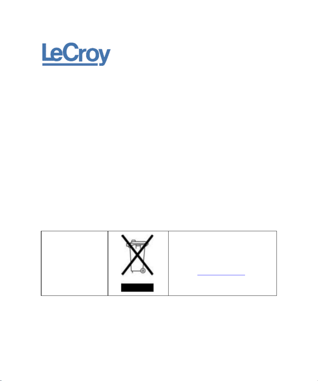
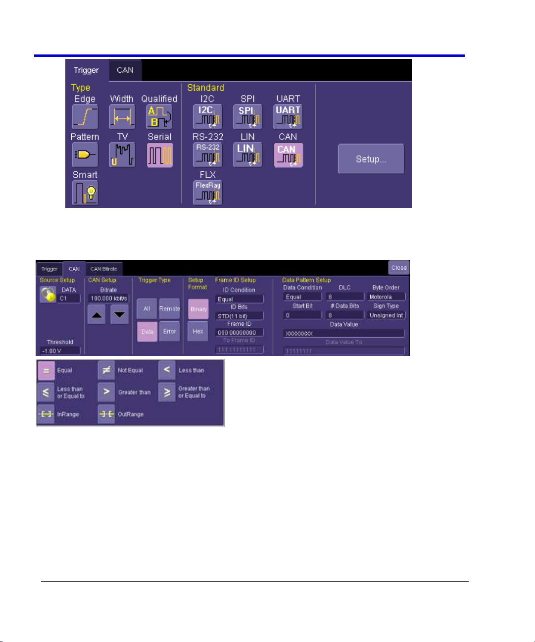
Accessing Serial Triggers
The CANbus serial trigger is accessed from the oscilloscope trigger dialog. Use one of the
following methods:
Touch the Trigger Descriptor Box in the lower right hand corner of the oscilloscope
display.
OR
Touch Trigger → Trigger Setup from the Menu Bar. On the Trigger dialog, touch Serial on
the Type section.
Select the appropriate serial trigger. The menu automatically changes to a different tab in
the Trigger dialog reflecting the selected standard.
Page 10
CANbus Trigger, Decode, and Measure
10
CANbus-TD-TDM-OM-E RevB
Creating a CANbus Trigger Condition
The CANbus Trigger dialog, with detail on some of the setup conditions, is shown in the
following topics.
CANbus Trigger Setup Detail
The following topics show the dialog selections for a CANbus Trigger.
Page 11
Operator's Manual
CANbus-TD-TDM-OM-E RevB
11
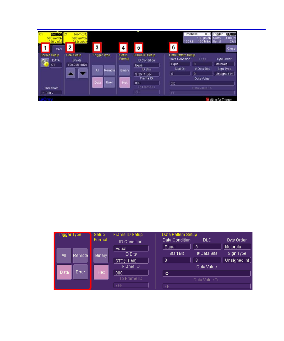
The previously numbered CANbus trigger sections correspond with the following explanations.
1. Source Setup
DATA - The DATA field's pop-up dialog is used to select the appropriate channel or EXT
input for each. Set this field up with caution or your trigger may not function correctly.
Use the Threshold field to adjust the vertical level for the trigger. Much like an Edge
trigger, a user must specify the level used in order to process the incoming signals and
determine whether the desired serial data pattern is meeting the set trigger condition.
2. CAN Setup
Bitrate - Use the Bitrate field to adjust the value and match the bus to which you are
connected. This bitrate selection is dynamically linked to the decoding bitrate (they are
always the same value). Use the arrows to move through standard bit rates (10, 25,
33.333, 50, 83.333, 100, 125, 250, 500, and 1000 kb/s) and make a selection. Or, touch
the number twice (with a finger, or using a mouse) and open a pop-up keypad and enter
the value directly.
3. Trigger Type
Trigger Type - Depending on your Trigger Type selection, certain Frame ID and Data
Pattern Setup fields are enabled or disabled as follows:
All - Triggers on all signals. No Frame ID and Data Pattern ID Setup fields are enabled.
Page 12
CANbus Trigger, Decode, and Measure
12
CANbus-TD-TDM-OM-E RevB
Remote - Only Frame ID Setup fields are enabled.
Data - Both Frame ID and Data Pattern ID Setup fields are enabled.
Error - Triggers only when an error signal occurs. No Frame ID and Data Pattern ID Setup
fields are enabled.
4. Setup Format
Select either Binary or Hexadecimal (Hex) setup mode. The mode selected propagates
through the entire CANbus trigger setup.
Try selecting Binary mode, and set up the Frame ID in binary format, then re-select HEX
mode and set up the data in hexadecimal format. Toggling back and forth between the
modes does not result in loss of information.
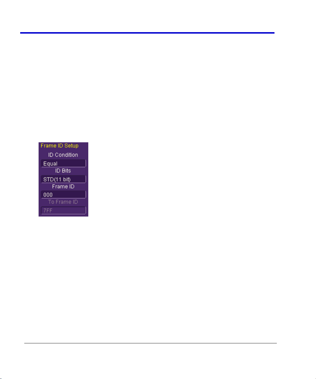
5. Frame ID Setup
Frame ID Setup is used to trigger on a specific Frame ID value with either 11 or 29 Bits.
When CANbus trigger selections are either Remote or Data, use the Frame ID Setup fields
as follows:
ID Condition - The ID condition can be set to many different values. If the ID condition is
set to “=”, then a data definition can also be set. Any other ID condition precludes setting
up a Data condition.
The ID condition can be set to <=, <, =, >, >=, not =, in a range, out of a range, or don’t
care.
ID Bits - The trigger can be set to trigger on CAN messages with either 11-bits (Standard
CAN) or 29-bits (Extended CAN). You can also set the trigger so that it triggers on a
message that meets a condition for either the 11-bit or 29-bit ID. For instance, there
might be an 11-bit ID value that is present in both an 11-bit and a 29-bit ID, and by
choosing ALL, you could trigger when that ID is present on either of those messages.
Frame ID - Specify the desired frame ID for triggering here.
Page 13
Operator's Manual
CANbus-TD-TDM-OM-E RevB
13
To Frame ID - When using an in range or out of range ID Condition (previous), specify a To
Frame ID value for triggering.
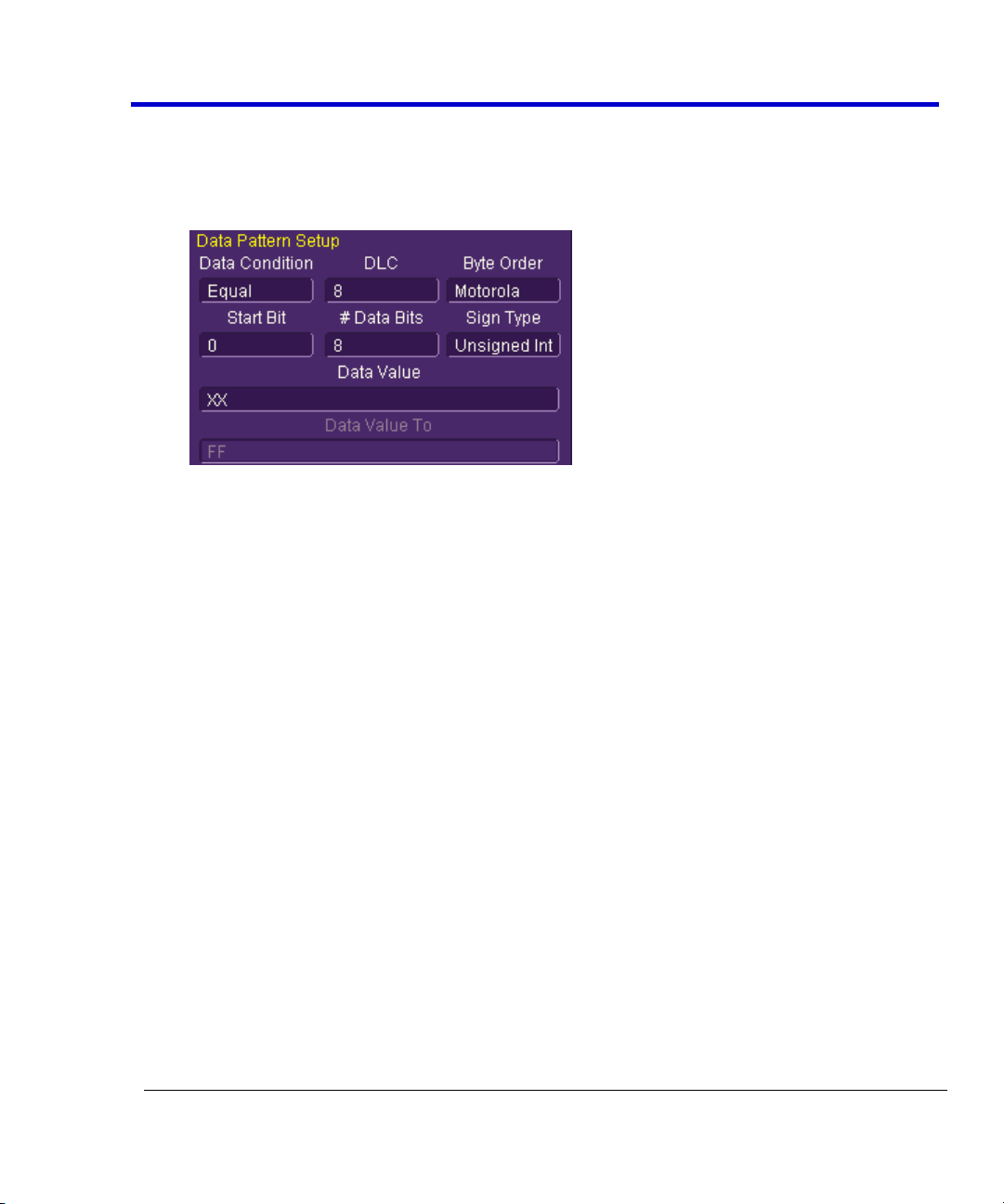
6. Data Pattern Setup
Fields on this section of the dialog are only enabled when using the Data trigger type.
Data Condition - The Data Condition can be set to many different values. The Data
condition can be set to <=, <, =, >, >=, not =, in a range, out of a range, or don’t care.
DLC - The DLC (data length code) can be set to any integer value from 0 to 8. It should
match the DLC of the CAN message you want to trigger on. If you set it to a value less
than 0, it will default to 0. If you set it to a value greater than 8, it will default to 8.
Byte Order - Choose from either Motorola (default) or Intel byte orders.
Start Bit and # Data Bits - The CANbus trigger allows you to trigger on up to 64
contiguous data bits (8 data bytes). This maximum 64-bit string can start at any location
in the CAN message data field - it is not limited to the start of a full byte or a nibble.
The Start Bit can be any value from 0 to 63. If you enter a value less than 0, it will default
to 0. If you enter a value more than 63, it will default to 63. The Start Bit value is always in
LSB format (i.e., the bit number as shown on the decoded waveform, with bit 0 being at
the far left and bit 63 being at the far right of the data string). Remember that the 1st
data byte is bits 0-7, the 2nd data byte is bits 8-15, etc. Also, make sure that your Start Bit
value makes sense in relation to the DLC Value. For instance, a Start Bit value of 32 with a
DLC Value of 4 is not going to result in a successful trigger.
The # Bits can be any value from 1 to 64. If you enter a value less than 1, it will default to
1. If you enter a value more than 64, it will default to 64.
Sign Type - Choose between signed and unsigned integer format.
Data Value and Data Value To - The Data Value is set in Binary or Hexadecimal format.
For Hexadecimal, if desired, you can precede the ID value with “0x”, but this is not
necessary. Be sure to enter a Data Value that matches the DLC Value.
Page 14
CANbus Trigger, Decode, and Measure
14
CANbus-TD-TDM-OM-E RevB
When using an in range or out of range Data Condition (previous), specify a Data Value
To value for triggering.
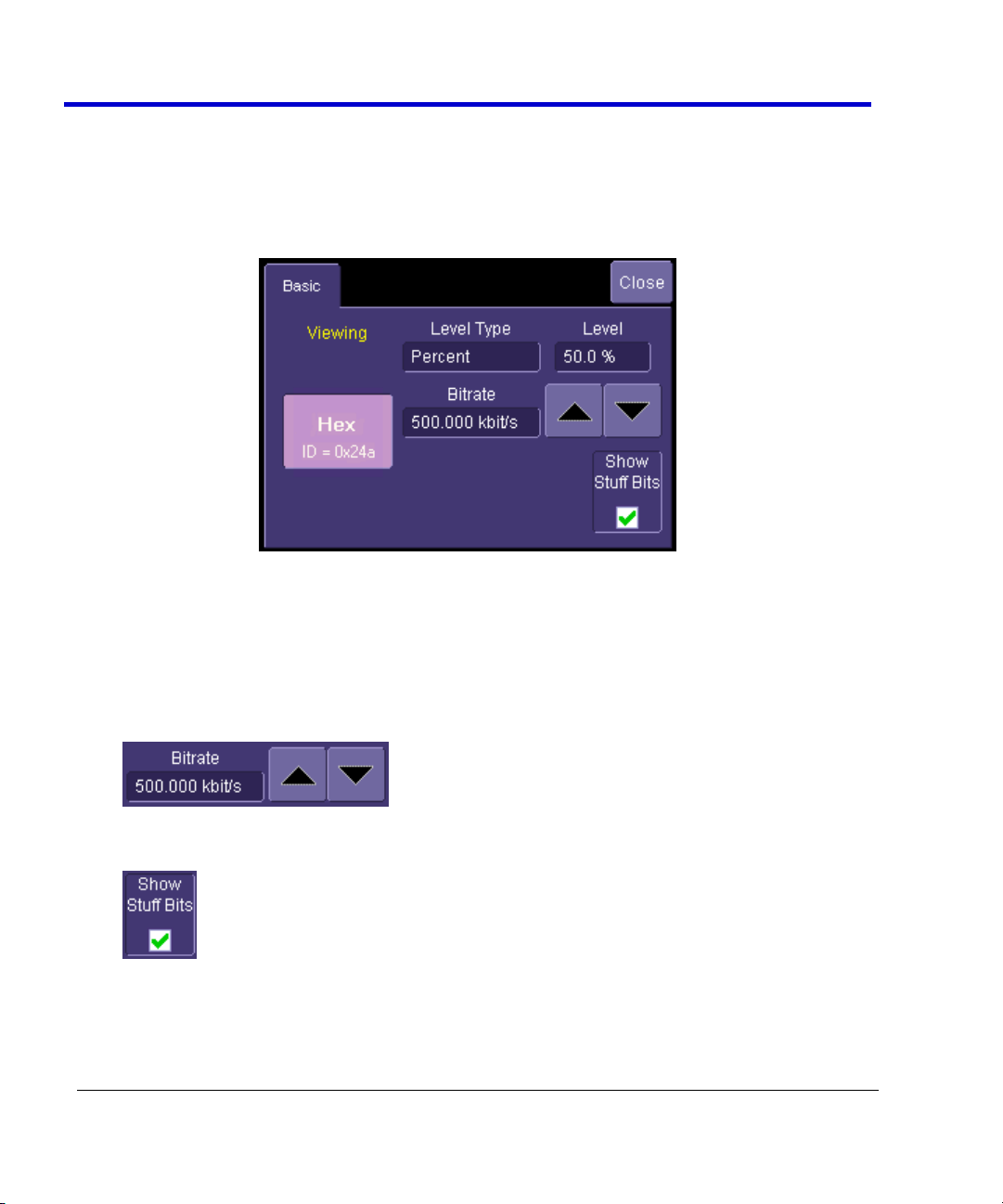
CANbus Decode Setup Detail
CANbus Decode Setup Right-Hand Dialogs are shown when CAN is selected as the decode
protocol. It provides detailed fields and setup conditions as follows:
Viewing - The decode format is displayed here as Hexadecimal for CANbus.
Bitrate - Adjust the bit rate value here to match the bit rate on the bus you are connected
to. This bit rate selection is dynamically linked to the decoding bit rate (they are always
the same value). Use the arrows to move through standard bit rates (10, 25, 33.333, 50,
83.333, 100, 125, 250, 500, and 1000 kb/s) and make a selection. Or, touch the number
twice (with a finger, or using a mouse) and open the pop-up keypad to enter the value
directly. Any value from 10-1000 kb/s may be entered in this way.
Show Stuff Bits – Use this checkbox to indicate whether you want stuff bits highlighted
on each CAN message frame.
Level Type and Level - The message decoding algorithm setup is performed here. The
level is normally set up in %, and defaults to 50%. To adjust the level, touch inside the
number area to highlight the box title in yellow, then use the oscilloscope front panel
Page 15

Operator's Manual
CANbus-TD-TDM-OM-E RevB
15
Adjust knob to adjust. Or touch inside the number area twice and select a value using the
pop-up numeric keypad.
The set Level appears as a dotted horizontal line across the oscilloscope grid.
If your initial decoding indicates that there are a number of error frames, make sure that
the level is set to a reasonable value.
Measuring CANbus Performance Using CANBUS
TDM
Overview of CANbus TDM (Trigger, Decode, Measure/Graph)
Basic oscilloscope tools can be extremely helpful to understand single-shot events. However,
their utility in measuring performance of a CAN Bus system can be very limited. It is usually
necessary to obtain large quantities of data before you can be sure that system performance is
within specified limits. The following are typical examples of actions to assess CAN Bus system
performance:
Measure Timing Δ Between CAN and Analog Signals & Accumulate Statistics - Measure
the time difference between an analog signal and CAN signal generated in response to it
(or vice-a-versa). View the mean, minimum, and maximum timing values, the number of
samples, and the standard deviation of the measurements.
Measure Timing Δ Between Two CAN Messages & Accumulate Statistics - Same as
previous, but with two CAN signals.
Measure Timing Δ From the Trigger Point to a CAN Message - Same as previous, but the
trigger point can be anything - a CAN message, an Analog signal, a Pattern of signals, a
Dropout condition, etc.
Measure Timing, Accumulate Statistics, View Distribution - Instead of just looking at
numerical values, graph/plot the distribution as a histogram to better understand the
shape of the distribution, the quantity of extreme events, and determine underlying
cause.
Graph/Plot CAN Data Values from a Single Acquisition - Extract CAN Data values in
decimal format and compare them to an analog signal in a time-correlated fashion.
Graph/Plot CAN Data Values Over Multiple Acquisitions - Extract CAN Data values in
decimal format and graph/plot them over multiple acquisitions.
Measure CAN Bus Load, Graph/Plot - Understand how bus loading relates to other CAN
and Analog signal events.
Page 16
CANbus Trigger, Decode, and Measure
16
CANbus-TD-TDM-OM-E RevB
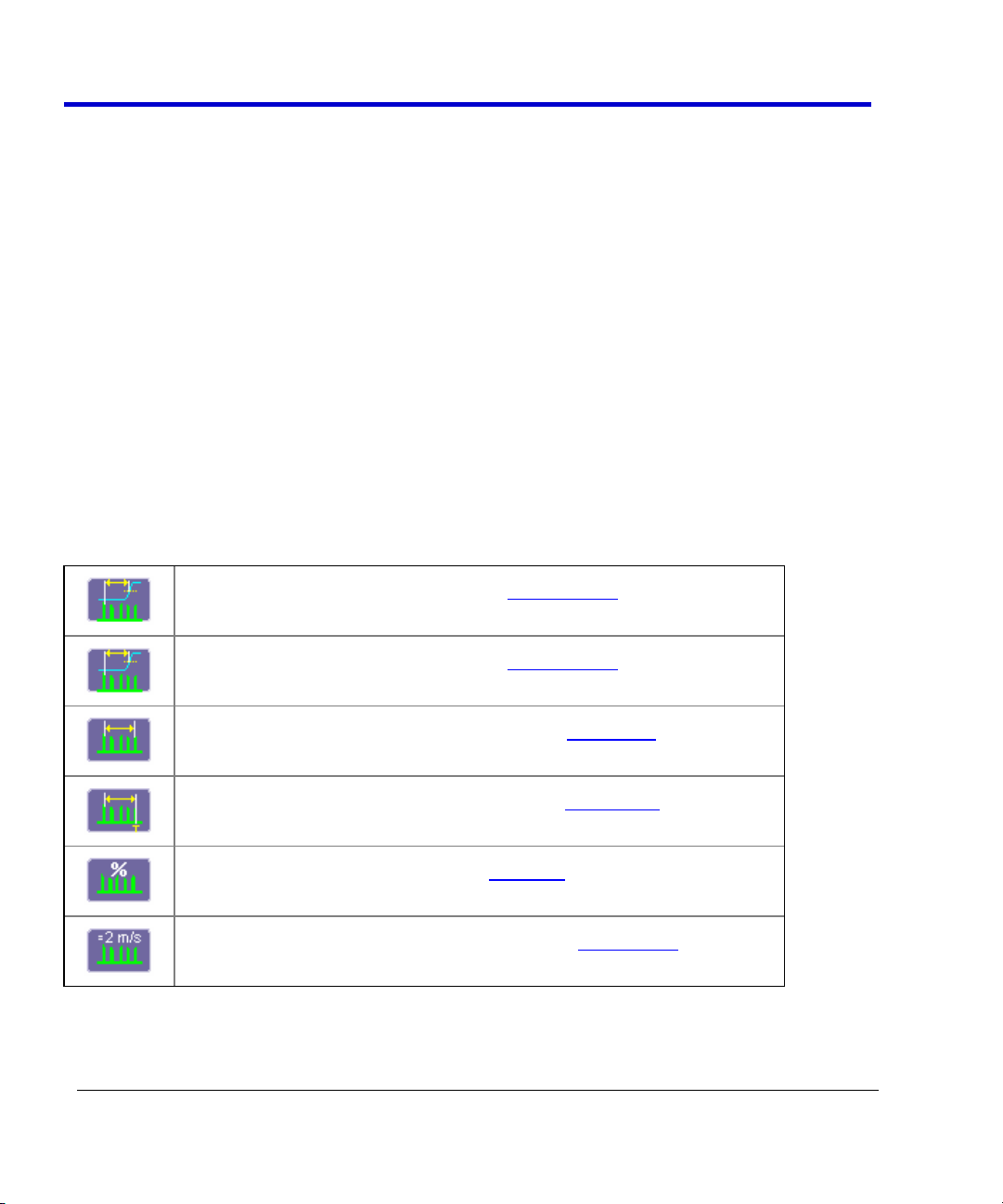
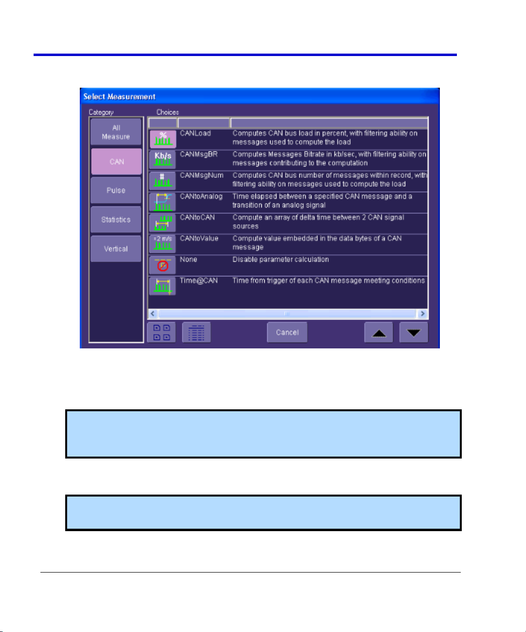
CAN Message to Analog Signal timing (CANtoAnalog)
Analog Signal to CAN Message timing (CANtoAnalog)
CAN Message to CAN Message Signal Timing (CANtoCAN)
Time from trigger to a specific CAN message (Time@CAN)
CAN Bus Message Load Percentage (CANLoad)
Extract CAN Message Data to a Decimal Value (CANtoValue)
Some of this information could be gathered using standard oscilloscope tools, but the
accumulation of the data would take hours or days. It is more likely that the engineer would
instead gather a very small sample set and skip the statistical evaluation in order to save time.
The result is reduced product quality and corresponding greater risk of shipping product that
functions incorrectly in some situations.
CANbus TDM contains specific CAN measurement parameters that allow you to quickly and
easily accumulate statistical information on a wide variety of events, and graphical display tools
to visualize the data on your oscilloscope screen. These sophisticated measurement and
graphical display tools are the “missing link” between standard oscilloscope and protocol
analyzer capability. The CANbus TDM tools provide the capability to trigger on defined CAN Bus
events, observe actions/reactions, measure timing among CAN and Analog signals, and view
results in a graphical fashion directly on the oscilloscope display with no complicated export of
data. Data on tens of thousands of events can be automatically and quickly gathered and
analyzed in a fraction of the time it takes to manually perform the same testing.
CANbus TDM contains additional CAN specific measurement, graphing, and statistical analysis
capability as the following topics explain.
CANBUS TDM Parameters
Page 17

Operator's Manual
CANbus-TD-TDM-OM-E RevB
17
CANbus TDM Graphing and Statistical Analysis
Histogram - The Histogram displays a statistical distribution of a measurement
parameter. Histogram is helpful to understand the modality of a measurement
parameter, and to debug the root cause of excessive variation.
Trend - The Trend statistical tool visualizes the evolution of a timing parameter over time
in the form of a line graph. The graph’s vertical axis is the value of the parameter; its
horizontal axis is the order in which values were acquired. Trend is typically used for a
multi-shot acquisition. Trend is analogous to a chart recorder.
Track - The Track displays a time-correlated accumulation of values for a single
acquisition. Track can be used to plot the values of CAN data and compare them to a
corresponding analog signal, or observe changes in timing. Track is typically used for a
single-shot acquisition. A long acquisition with many parameter measurements analyzed
with Track could provide information about the modulation of the parameter.
Page 18

CANbus Trigger, Decode, and Measure
18
CANbus-TD-TDM-OM-E RevB
In addition to the Histogram graphing capability, there are also 19 different measurement
parameters that apply specifically to Histograms. These are listed below (more information is
contained in Appendix D):
fwhm - full width (of largest peak) at half the maximum bin
fwxx - full width (of largest peak) at xx% the maximum bin
hist ampl - histogram amplitude between two largest peaks
hist base - histogram base or leftmost of two largest peaks
hist max - value of the highest (right-most) populated bin in a histogram
hist mean - average or mean value of data in the histogram
hist median - value of the x-axis of a histogram that divides the population into two
equal halves
hist min - value of the lowest (left-most) populated bin in a histogram
hist rms - rms value of data in histogram
hist sdev - standard deviation of values in a histogram
hist top - histogram top or rightmost of two largest peaks
max populate - population of most populated bin in histogram
mode - data value of most populated bin in histogram
percentile - data value in histogram for which specified `x'% of population is smaller
peaks - number of peaks in histogram
pop @ x - population of bin for specified horizontal coordinate
range - difference between highest and lowest data values
total pop - total population in histogram
x at peak - x-axis position of specified largest peak
These measurement parameters are available in the Statistics category in the measurement
selection pop-up dialog.
General Setup of CANbus TDM Parameters
There are two different ways to set up CAN related measurements. The easiest way is to use the
Measure tab in the CAN Analysis dialogs to access the CAN Measure dialog. This dialog is
specifically tailored to meet the needs of an engineer who is debugging CAN-based systems. It
contains different categories of CAN, pulse, statistical, etc. measurement parameters that are
commonly used to measure CAN system performance.
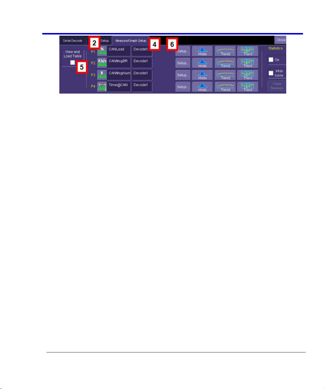
Setting Up CANbus Parameters using the Serial Decode option
1. Touch the Measure/Graph Setup tab in the CAN Serial Decode dialogs. There are four
parameter measurements displayed (P1 through P4).
Page 19
Operator's Manual
CANbus-TD-TDM-OM-E RevB
19
Page 20
CANbus Trigger, Decode, and Measure
20
CANbus-TD-TDM-OM-E RevB
2. For a specific measurement parameter, touch the parameter icon or parameter name to
access the CAN Measurement Select pop-up dialog.
3. From the CAN Select Measurement window, choose a parameter. Touch an icon to select
the measurement.
4. Touch the source field to open the Select Source pop-up dialog. Select a category to
display the available sources, then select the appropriate source.
Note:The source for the CAN measurements should be Decode1, Decode2, Decode3 or
Decode4 depending on which serial data decode is being used to decode the bus you
are trying to measure.
5. The View and Load Table checkbox is checked automatically when you select your
parameters. Uncheck it to turn measurements OFF.
Note: Measurement parameter and source selections that are set up in the CAN
Measure menu are copied to the oscilloscope standard Measure menu.
Page 21

Operator's Manual
CANbus-TD-TDM-OM-E RevB
21
6. Many parameters (and all CAN-specific parameters) require some additional setup
information to be entered in order to work correctly. To access the setup dialog, touch
the Setup button.
Page 22

CANbus Trigger, Decode, and Measure
22
CANbus-TD-TDM-OM-E RevB
Setting Up CANbus Parameters using the Measure Setup option
You can also set up measurement parameters using the Measure menu as follows:
Touch Measure→Measure Setup. select the appropriate CAN or other parameter. For more
information, see Parameter Setup in the oscilloscope's Online Help or Operator's Manual.
Note: All CAN measurement parameters (with the exception of CAN Load %) calculate as many
values as possible during each acquisition. If there are 10 timing events that meet the set
condition during a specific acquisition, 10 timing event measurements will be returned.
However, the VALUE shown in the measurement table is the last measurement made. To view
statistical data (i.e., number of measurements made, mean, min, max, std. dev.), turn Statistics
ON.
CAN Load % returns only one value during each acquisition, since it is evaluating the load % for
the entire acquisition time.
CAN-to-Analog or Analog-to-CAN Measurement Parameter
CAN Message to Analog Signal timing (CANtoAnalog)
This measurement parameter is used to measure timing from either a CAN Message to an
Analog Signal, or from an Analog Signal to a CAN Message. The Frame Type, ID, DATA, etc.
conditions for the CAN message can be fully defined, as can the slope, level, etc. conditions for
the analog signal transition.
If measuring from CAN to Analog, the timing is always measured from the End of Frame of CAN
message to the analog signal transition. If measuring from Analog to CAN, the timing is always
measured from the analog signal transition to the Start of Frame of the CAN message.
Page 23

Operator's Manual
CANbus-TD-TDM-OM-E RevB
23
Note: Source 1 should always be defined as the CAN Decode source and Source 2 should
always be defined as your Analog Signal (either a channel, memory, etc.), regardless of
whether you wish to measure from CAN to Analog or Analog to CAN. Analog to CAN values will
simply be reported as negative values.
Page 24

CANbus Trigger, Decode, and Measure
24
CANbus-TD-TDM-OM-E RevB
CAN-to-Analog Parameter Setup
To access the setup dialog, touch Setup for that particular parameter on the CAN
Measure/Graph Setup dialog. The Px Parameter dialog will be displayed. On the right side of this
dialog box, there is an additional setup dialog:
The CAN Message tab defines the CAN Message Setup. The Analog Signal tab defines the Analog
Signal Setup.
Note: The CAN Message tab always defines the CAN Message Setup and the Analog Signal tab
always defines the Analog Signal setup even if you are measuring time from an Analog Signal
to a CAN Message. The CAN Message setup is nearly identical to the setup of the CAN message
in the CAN Trigger dialog, so details will not be repeated here.
The Analog Signal setup dialog is shown below:
Page 25

Operator's Manual
CANbus-TD-TDM-OM-E RevB
25
Select the measurement level as Percent or Absolute, and set a value. Then select the slope of
the edge to which you want to measure. The Hysteresis selection imposes a limit above and
below the measurement Level, which precludes measurements of noise or other perturbations
within this band. The width of the band is specified in milli-divisions. Guidelines for using
Hysteresis are as follows:
Hysteresis must be larger than the maximum noise spike you want to ignore.
The largest value of hysteresis usable is less than the distance from the level to the
closest extreme value of the waveform.
Unless you know the largest noise and closest extreme level that will ever occur on any
cycle, leave some margin on both sides of the level.
Note: Various pathological conditions can block the computation of the CANtoAnalog and
CANtoCAN parameters. In all cases, the cause of the condition can be viewed on the message
line by clicking on the yellow icon , below the measurement parameter values.
The simplest, and most common, reason for non-computation of the CAN timing parameters is
that none of the CAN Message or Analog Signal conditions defined in the right-hand dialog is
encountered in the whole record processed by the algorithm. In this case the error message
will be "Cannot find Start and/or End condition on input of CAN2CAN or CAN2Analog."
Another possible cause is that the time frames of the 2 inputs specified do not overlap at all.
The error message will be "No Common Time Span exists between inputs"
Finally, the sequence of occurrence of the CAN Message or Analog Signal conditions defined in
the right-hand dialog setup tab can lead to ambiguous results. (Too many CAN conditions for
each Analog condition, nested CAN and Analog conditions). In this case the message line will
show: "Ambiguous Start/End time relationship for CAN2CAN or CAn2Analog".
CAN Message-to-CAN Message Measurement Parameter
CAN Message-to-CAN Message timing (CANtoCAN)
This measurement parameter is used to measure timing values between two CAN Messages.
The Frame Type, ID, DATA, etc. conditions for the CAN message can be fully defined for both
CAN messages. The timing is always measured from the End of Frame of the first CAN message
to the Start of Frame (SOF) of the second CAN message.
Page 26

CANbus Trigger, Decode, and Measure
26
CANbus-TD-TDM-OM-E RevB
CANtoCAN Measurement Parameter Setup Detail
To access the setup dialog, touch Setup for that particular parameter on the CAN
Measure/Graph Setup dialog. The Px Parameter dialog is displayed. On the right side of this
dialog box, there is a setup dialog labeled with the measurement parameter name. Touch the
tab with the parameter name on it to access the following dialog:
The Start Message tab defines the first CAN Message Setup. The End Message tab defines the
second CAN Message Setup.
Note: The CAN Message setup is nearly identical to the setup of the CAN message in the CAN
Trigger dialog, so details will not be repeated here.
The two CAN message definitions can be different, or they can be the same. If they are different,
the time value measured will be from the first CAN message to the second, with a positive value
indicating that the second message occurred after the first message, and a negative value
indicating that the second message occurred before the first.
If you wish to measure the time between two identical CAN messages, the Data Condition must
be set to “Don’t Care.” Then, if there are “n” CAN messages that satisfy the condition, you will
get “n-1” measurements. Measurements would be made between all adjacent pairs that satisfy
the condition.
Note: Various pathological conditions can block the computation of the CANtoAnalog and
CANtoCAN parameters. In all cases, the cause of the condition can be viewed on the message
line by clicking on the yellow icon , below the measurement parameter values.
The simplest, and most common, reason for non-computation of the CAN timing parameters is
Page 27
Operator's Manual
CANbus-TD-TDM-OM-E RevB
27
that none of the Start or End condition defined in the right-hand dialog is encountered in the
whole record processed by the algorithm. In this case the error message will be "Cannot find
Start and/or End condition on input of CAN2CAN or CAN2Analog."
Another possible cause is that the time frames of the 2 inputs specified do not overlap at all.
The error message will be "No Common Time Span exists between inputs"
Finally, the sequence of occurrence of the Start or End conditions defined in the right-hand
dialog can lead to ambiguous results. (Too many Start conditions for each End condition,
nested Start and End conditions). In this case the message line will show: "Ambiguous
Start/End time relationship for CAN2CAN or CAn2Analog."
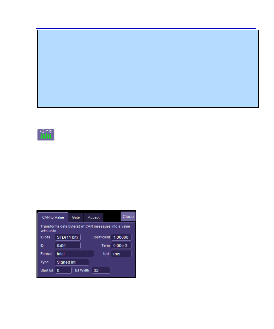
Extract CAN Message Data to a Decimal Value
Extract CAN Message Data to a Decimal Value (CANtoValue)
This measurement parameter is used to extract CAN message data in any sequential byte/bit
location and display it as a decimal value that is rescaled to specific operator set units of
measure. Essentially, it allows the conversion of a bit field embedded into a CAN message into a
value with user-definable units.
CANtoValue Measurement Parameter Setup Detail
To access the setup dialog, touch Setup for that parameter in the CAN Measure/Graph Setup
dialog. The Px Parameter dialog box is displayed. On the right side of this dialog box, there is a
setup dialog labeled with the measurement parameter name. Touch the tab with the parameter
name on it, and you will access the following dialog:
Page 28

CANbus Trigger, Decode, and Measure
28
CANbus-TD-TDM-OM-E RevB
You must specify the ID length and ID Value for the CAN Messages that you wish to extract data
from. The measurement parameter will process all messages meeting the ID condition in the
acquisition, and apply the same conversion to them.
The conversion process requires the Format in which the value is embedded (Intel or Motorola),
the Type of value (Integer of Float) and the bit window occupied by the value. The window is
specified with a Start Bit and a Bit Width for integers. Floating point values always use a Bit
Width of 32.
Finally, the last stage of the conversion process transforms the raw value into a physical value
with units, using a linear transformation of the type Parameter Value = Coefficient * Raw Value
+ Term. Units can be specified as well, provided they belong to the list given in "Rescaling and
Assigning Units" under Waveform Math. The unit specified here will propagate throughout the
system to the parameter value, subsequent Tracks and Trends, and cursor readout on any
derived function.
Note: The default coefficient and term will apply no transformation to units of the raw value.
All the entries required in this dialog are usually provided by sensor or actuator manufacturers,
or can be read out of commercially available tools using DBC files.
Using this measurement parameter, you can graph data using the Trend or Track function.
CAN Bus Message Load Percent Measurement Parameter
CAN Bus Message Load Percentage (CANLoad
This measurement parameter is used to measure total bus load within the captured record for
messages that meet a defined set of conditions. The “load” formula is the sum of the message
length(s) from SOF to EOF divided by total acquisition length.
CANLoad Measurement Parameter Setup Detail
To access the setup dialog, touch Setup for that parameter in the CAN Measure/Graph Setup
dialog. The Px Parameter dialog box is displayed. On the right side of this dialog box, there is a
setup dialog labeled with the measurement parameter name. Touch the tab with the parameter
name on it, and you will access the following dialog:
Page 29

Operator's Manual
CANbus-TD-TDM-OM-E RevB
29
Frame type can be ALL, Remote, Data, or Error type. ID conditions can be set, and IDs specified.
The operation is much the same as the CAN Trigger setup, so the detail will not be repeated
here.
Page 30

CANbus Trigger, Decode, and Measure
30
CANbus-TD-TDM-OM-E RevB
Time from Trigger Point to CAN Message Parameter
Time from Trigger Point to CAN Message (Time@CAN)
This measurement parameter is used to measure the time from the trigger point to the defined
CAN message. The trigger could be a CAN message, a simple edge trigger, or something more
complicated, like a Pattern or a Dropout SMART Trigger. This makes it a very powerful tool to
understand the time delay from the occurrence of a certain set of conditions to the start of a
CAN message.
Time@CAN Measurement Parameter Setup Detail
To access the setup dialog, touch Setup for that parameter in the CAN Measure/Graph Setup
dialog. The Px Parameter dialog box is displayed. On the right side of this dialog box, there is a
setup dialog labeled with the measurement parameter name. Touch the tab with the parameter
name on it, and you will access the following dialog:
Characterizing CANbus System Performance
System Performance Characterization Overview
The oscilloscope contains a number of built-in tools, such as cursors, measurement parameters,
statistics, and optional graphical analysis tools that you can use to characterize your CANbus
system’s performance. These can be used on the CAN Trace and CAN Zoom just like they are
used on any channel. In addition, you can use normal Edge or SMART Triggers on an analog
channel input to trigger the oscilloscope when a certain analog signal occurs, and then measure
to a particular CAN message.
Page 31

Operator's Manual
CANbus-TD-TDM-OM-E RevB
31
You can use cursors for making single-shot timing measurements, and measurement parameters
when you need to accumulate statistical data over many different acquisitions. In addition,
measurement parameters are helpful to determine the underlying integrity of the CAN physical
signal.
Page 32

CANbus Trigger, Decode, and Measure
32
CANbus-TD-TDM-OM-E RevB
For instance, take the example below of an analog signal creating a burst of CAN messages.
This data was acquired over a 500 ms duration. It is likely that you want to understand whether
the analog signal input to your electronic control unit (ECU) is creating the desired CAN message
output from the ECU. There are a number of ways that this could be done.
Using Cursors
Use horizontal cursors to mark locations on the waveform where the time measurement should
be done, then read the cursor values to establish the measurement. As necessary, adjust the
timebase or create zooms of the channels and the CAN Trace to view the signal with enough
detail. This is a good method for single-shot / single measurements.
Page 33

Operator's Manual
CANbus-TD-TDM-OM-E RevB
33
Page 34

CANbus Trigger, Decode, and Measure
34
CANbus-TD-TDM-OM-E RevB
Amplitude - Noise and overshoot resistant measurement of the amplitude of the signal
(measurement of amplitude from Top to Base).
Base - Value of the lowermost state in a bimodal waveform, such as a CAN Message.
Delay - Time from the trigger to the first transition at the 50% amplitude crossing.
Delta Delay - Time between the 50% crossing of the first transition of two waveforms.
Delta Time @ Level - Time between selectable levels of two waveforms.
Delta Trig Time - The time from last trigger to this trigger (usually used in Sequence
mode).
Fall (90-10), Fall 80-20, Fall@Level - Transition time on the falling edge. Three selections
are available for the user to determine at which vertical level the measurement is made.
Maximum - Highest value in the input waveform.
Mean - Average of all data values.
Minimum - Lowest value in the input waveform.
Overshoot Negative - Overshoot following a falling edge.
Overshoot Positive - Overshoot following a rising edge.
Using Measurement Parameters
You can use measurement parameters to make signal integrity or timing measurements of your
CAN Bus system. Basic parameters, such as Amplitude, Rise, Fall, Overshoot, etc. are ideal for
signal integrity checks. Timing parameters, such as Delay, Delta Delay, Delta Time @ Level, etc.,
are ideal for measuring timing from trigger to other signals (such as from a CAN Trigger to an
analog signal). Delta Trig Time is ideal for measuring the time between segments of a Sequence
Mode acquisition.
Page 35

Operator's Manual
CANbus-TD-TDM-OM-E RevB
35
Peak to Peak - Difference between the Maximum and Minimum data values.
Rise (10-90), Rise (20-80), Rise@Level - Transition time on the rising edge. Three
selections are available for the user to determine at which vertical level the
measurement is made.
Top - Value of the uppermost state in a bimodal waveform, such as a CAN Message.
Measurement Gating
Gating is available on each parameter to allow you to set a measurement window that the
parameter should be active in. This allows you to eliminate unwanted portions of the
acquisition from your measurement.
1. Touch the the appropriate measurement (P1, P2, etc.) or choose Measure→Measure
Setup and then touch the appropriate measurement tab (P1, P2, etc.).
2. Touch the Gate tab and enter the start and stop for the gate.
Using Statistics and Graphing
Statistics and Histicons are included with every LeCroy oscilloscope. They allow you to gather
numerical and visual information on the distribution of your various measurements.
You can turn on Statistics and Histicons separately in the Measure dialog. Touch the
appropriate box to place a checkmark and turn it ON, or touch it again to turn it OFF.
Page 36

CANbus Trigger, Decode, and Measure
36
CANbus-TD-TDM-OM-E RevB
In addition, some optional LeCroy programs add the capability to produce larger histograms and
trends of your measurement parameters. If you have this capability, then you can access it
through the Measurement Parameter setup dialog (the Px tab).
Pass/Fail Analysis with Measurement Parameters
Pass/Fail analysis using measurement parameters is simple to set up and powerful. For
instance, you can define a timing measurement, define the limits for the timing measurement,
and then run the oscilloscope in a Normal trigger mode, capturing thousands of measurement
events. Then, Pass/Fail can be used to save the waveform in the event of a Fail, or send an
email in the event of a fail.
Page 37

Operator's Manual
CANbus-TD-TDM-OM-E RevB
37
Touch Analysis→Pass/Fail Setup to set up pass/fail conditions.
Isolating and Analyzing CANbus Activity
Isolate and Analyze Serial Bus Activity
The combination of Serial Data Triggering, Decoding, and normal oscilloscope features is a
powerful combination of tools that can make it very easy to find latent Serial Data HW or SW
problems in your circuit. No longer is the oscilloscope a tool just for the hardware engineer.
Now the software engineer can also easily visualize the Serial Data signals and relate it to
programming code and operation. The TD options can enable the HW Engineer and SW Engineer
to “speak the same language” when it comes to system debugging and performance checking.
Some common Serial Data analysis needs and methods are discussed below:
Capture Long Pre-Trigger Time
LeCroy oscilloscopes are available with optional very long acquisition memory. For instance, the
WaveRunner Xi Series oscilloscopes can capture up to 12.5 Mpts on 4 channels, or 25 Mpts on 2
channels. If your Serial Data signals are 1 Mb/s, and you sample at the minimum required and
available sample rate (5 MS/s, you would be able to capture 5 seconds of Serial Data traffic. If
you wish, this can be 100% pre-trigger, 100% post-trigger, or something in between.
1. Adjust Pre-Trigger and Post-Trigger time by adjusting the Delay knob on the oscilloscope’s
front panel.
Page 38

CANbus Trigger, Decode, and Measure
38
CANbus-TD-TDM-OM-E RevB
2. Optimize your Sample Rate or Memory Length by accessing the Horizontal Dialog in your
oscilloscope and selecting either Set Max Memory mode or Fixed Sample Rate mode.
3. Touch Set Maximum Memory to decrease the memory usage in order to not sample at
rates you specify as being too high (high sample rates can slow down the decoding
algorithm). Then adjust your time timebase setting to the length needed to capture the
event.
Note: Make sure your combined timebase and memory length settings do not result in
too low of a sample rate. Otherwise, adequate capture and decode is not performed.
4. Touch Fixed Sample Rate to specify a fixed rate. It's common to fix the sample rate to a
specified value so you have the necessary oversampling to capture your Serial Data
messages (at least 4X the bit rate). This also allows for a high enough sample rate to
capture transients you may want to see on your Serial Data and analog signals (at least 2X
the frequency of any expected transients, preferably 10X).
Reference your oscilloscope’s Online Help for more information on these common settings.
Trigger Repeatedly, Save Data to a Hard Drive
You may want to set up your oscilloscope to capture a short or long memory acquisition for a
certain trigger condition, then save data to a hard drive or memory stick whenever the trigger
condition is met. This can be easily done in most LeCroy oscilloscopes. However, there is
significant trigger “dead time” when using this method. To minimize dead time, use the method
described inTrigger Repeatedly, Store all Triggers (Sequence Mode).
1. Set up your desired serial data (or other) trigger condition.
2. Choose File →Save Waveform from the menu bar. A dialog is shown where you can set
Save Waveform conditions as follows:
OFF - No Auto Saving occurs
WRAP - Auto Save occurs until the hard drive is filled, then discards the oldest data to
write the newest data
Page 39

Operator's Manual
CANbus-TD-TDM-OM-E RevB
39
FILL - Auto Save occurs until the hard drive is filled
PLEASE NOTE THE FOLLOWING:
Choose a Binary file format if you want to recall the traces into a LeCroy oscilloscope for
later analysis.
Even though the LeCroy oscilloscope hard drives are very large, it is a good idea to make
sure that your trigger condition is set correctly before beginning your acquisitions.
This method is not guaranteed to capture all of your trigger events, since there is a large
amount of “dead time” between triggers as the acquisition is captured, displayed, and
stored to the hard drive before the scope is re-armed for a new trigger. Minimize dead
time by using Sequence Mode.
Trigger Repeatedly, Store all Triggers (Sequence Mode)
LeCroy oscilloscope’s have a powerful capability called Sequence Mode that allows you to store
all triggered events by minimizing the dead time between triggers to < 800 nanoseconds. This is
ideal for finding repetitive causes of problems on your serial data buses or associated signals.
(Not available in WaveSurfer Series).
Sequence Mode uses long acquisition memory that is divided into “segments.” As triggered
events are acquired, they are stored in acquisition “segments” to be recalled at a later date. The
length of each sequence mode acquisition segment and the total number of segments allowed is
roughly determined by the total acquisition memory in the oscilloscope. For instance, a
WaveRunner Xi with VL memory can acquire 10,000 segments each a maximum of 625 samples
long or 10 segments each a maximum of 1.25 megasamples long, or something in between.
Different acquisition memory lengths have different ranges of segments and segment lengths.
You can define any number of segments from 2 to the maximum for that memory length
(reference your oscilloscope’s on-line Help), and any length of segment (as long as there is
sufficient acquisition memory). After acquisition of all segments is complete, you can recall them
one-by-one and view them in decoded format on the oscilloscope screen.
Page 40

CANbus Trigger, Decode, and Measure
40
CANbus-TD-TDM-OM-E RevB
Acquisition dead time is kept to a minimum because there are no operations performed during
the acquisition. All data for each triggered event is written only into high-speed acquisition
memory. Until the entire sequence is completed, there is no updating of the oscilloscope
display, or other operations that cause unnecessary dead time. This is ideal for situations when
you cannot take a chance on losing data.
In the example shown below, we have only acquired Channel 1 (the CAN signal) in sequence
mode. We could also acquire additional analog or other signals as desired or as necessary to do
a proper analysis.
1. Touch the Timebase descriptor box to open the Timebase dialog.
2. In the Sampling Mode area, select Sequence Mode. Touch the Sequence tab.
3. On the Sequence tab, select the Display Mode. Select the Number of Segments Displayed
at one time.
4. If you have acquired more segments than you can display at one time, you can choose
the segment at which to start the display.
5. Set up the Serial Trigger to capture an event. For instance, you might want to trigger on a
specific address or data value, and capture long pre-trigger time to determine what
precedes that message. In this example, we’ve used a simple I2C Start trigger. To begin
the sequence mode acquisition, press the front panel SINGLE trigger button. Each time
the trigger condition is met, the TRIG’D light on the front panel flashes. When you’ve
acquired the set number of segments, the trigger STOPS and the following display is
shown (this is a 50 segment acquisition in Mosaic display mode).
Page 41

Operator's Manual
CANbus-TD-TDM-OM-E RevB
41
6. Display an individual segment separately from the main channel display by selecting
Math→Math Setup from the menu bar. Then, choose a math trace to define as a
Segment (here we’re defining F1 as a Segment of C2).
Page 42

CANbus Trigger, Decode, and Measure
42
CANbus-TD-TDM-OM-E RevB
Use the channel the serial data was acquired on as a source (in this case Channel 2).
Check the TRACE ON checkbox to display the trace. Select a segment to view by touching
the Select tab and use either the pop-up keypad or the front panel adjust knob.
7. Set up the Decode to use the Math trace as the source for Data in order to view decoded
data on the individual segment (in this case F4 is the source).
Page 43

Operator's Manual
CANbus-TD-TDM-OM-E RevB
43
To change the decoded segment, select a new segment from the Math trace dialog (as
shown in the preceding step).
8. Conserve display space, by turning off the Channel and selecting only the segment you
want to view.
Page 44

CANbus Trigger, Decode, and Measure
44
CANbus-TD-TDM-OM-E RevB
9. View the timestamps for each segment by selecting Vertical→Channels Status on the
menu bar. On the Show Status portion of the dialog, select Time. A display of timestamp
information for each segment in the sequence acquisition is shown.
10. Ten timestamps fit on the display at a time. You can choose which 10 to display by using
the Select Segment control. You can also page through the segments one at a time by
using the Adjust knob on the front panel.
Page 45

CANbus-TD-TDM-OM-E RevB
45
Reference
Definition
CANbus TD and TDM
Protocol Setup
Select Bitrate (10, 25, 33.333, 50, 83.333, 100, 125, 250, 500, 1000 kb/s
or user-defined between 10-1000 kb/s).
Decode Capability
CANbus TD and TDM
Format
Hexadecimal
Decode Setup
Threshold definition required. Default is to Percent amplitude. Select
BitRate.
Decode Input
Any analog Channel, Memory or Math trace.
Number of Decoded
Waveforms
Up to 4 buses may be decoded at one time.
In addition, zooms can be displayed (with decoded information).
Location
Overlayed over DATA waveform, on Grid.
(Use multi-grid if there is more than one decoder ON)
Visual Aid
Color Coding for FRAME, ID, DLC, DATA, CRC, Ack, Stuff Bits and Errors.
Decode information is intelligently annotated based on timebase setting.
Trigger Capability
CANbus TD and TDM
Format
Hexadecimal or Binary
Trigger Setup
Trigger on All Frames, Frame ID, ID with Data, Remote Frames, or Error
Frames.
Address (ID)
Condition Setup
Specify one Frame ID or a range of Frame IDs. Frame ID trigger can be
combined with Data.
Conditional Trigger
Setup
Conditional Frame ID and Conditional Data triggering available. Choose
from <=, <, =, >, >=, <>, in range, out of range or don’t care conditions.
Data Setup
Hexadecimal:
CANbus TD and TDM Specifications
Note: Specifications are subject to change without notice.
Operator's Manual
Page 46

CANbus Trigger, Decode, and Measure
46
CANbus-TD-TDM-OM-E RevB
Trigger Capability
CANbus TD and TDM
# Data Bytes = 0 to 8. Data can be defined by nibble. Triggers on that
data pattern regardless of position.
Binary:
Any combination of 0,1, or X for 1-64 bits. Triggers on that data pattern
regardless of position.
Bit Rates
10, 25, 33.333, 50, 83.333, 100, 125, 250, 500, 1000 kb/s or user-defined
between 10-1000 kb/s.
Trigger Input
Any analog Channel or the EXT input.
Trigger Design
Internal to oscilloscope, settable like any other oscilloscope trigger.
Search Capability
CANbus TD and TDM
Search Options
Search for Any Frame, Any Error or Frame ID in Hexadecimal format.
Measure and Graph
Capability
CANbus TD
CANbus TDM
CAN Timing
Measurements
Not Applicable
CAN-CAN, CAN-Analog, Time@CAN,
CAN Message Bitrate.
CAN Data Extraction
Not Applicable
CAN-Value.
CAN Bus Load
Measurements
Not Applicable
CAN Bus Load %.
Graphing Functions
Not Applicable
Track, Trend and Histogram of CAN
measurements.
Page 47

Operator's Manual
CANbus-TD-TDM-OM-E RevB
47
Safety Requirements
WARNING
To avoid personal injury and to prevent damage to this product or any products connected to it, review
the following safety precautions. To avoid potential hazards, use this product only as specified.
Before using the CANbus TD, ensure that its operating environment will be maintained within these
parameters:
Operation: In-door Use
Temperature: 5 to 40 oC
Humidity: < 80% RH (non-condensing)
WARNING
To avoid fire or personal injury, comply with the following:
Do not use the CANbus TD Series hardware in wet or explosive atmospheres.
Do not use the CANbus TD Series hardware if any part is damaged. All maintenance should be
referred to qualified service personnel.
Use of the CANbus TD Series hardware and/or the oscilloscope it is connected to in a manner
other than specified may impair the protection mechanisms.
Page 48

CANbus Trigger, Decode, and Measure
48
CANbus-TD-TDM-OM-E RevB
Qty. 1: Trigger Module -- The Trigger Module is basically a
CAN Node that is set to filter (and provide a triggering
signal) when certain conditions are met. It contains a 32bit, 64 MHz microcontroller and two Philips SJA1000 CAN
controllers. A Trigger Coupler (CAN transceiver) needs to
be installed in the trigger module to connect to the
appropriate bus. A 251 Trigger Coupler is provided
standard on input 1, and a second can be installed on input
2. As necessary, the trigger couplers can be interchanged
to suit your specific needs. The Trigger Module receives
triggering instructions, as defined in the CAN Trigger dialog,
through the USB2.0 cable (connected to the LeCroy
oscilloscope), and outputs a trigger pulse through the 3-pin
connector when the CAN trigger condition is met. The
trigger pulse is a negative going edge from 5 V to 0 V.
Qty. 1: Oscilloscope Interface Module -- This module
connects to the Trigger Module via the 3-pin connector.
The module is LeCroy ProBus® compatible. When plugged
into a LeCroy oscilloscope, it is automatically recognized
and proceeds with appropriate setup for CAN triggering.
The OIM can be connected to any channel, but is more
commonly connected to the EXT input (to reserve a channel
for an analog signal). Once connected, it sets the following:
sets the oscilloscope trigger to a negative going Edge
with a trigger level of 3 V (to trigger on the output
pulse when the CAN trigger condition is met) and no
trigger holdoff condition.
displays the CAN trigger dialog
applies a skew correction to all channels (to ensure
that the trigger point aligns with the EOF point of the
Appendix A: External Trigger Hardware
CANbus TD Standard Hardware
The Standard Hardware consists of the following items:
Page 49

Operator's Manual
CANbus-TD-TDM-OM-E RevB
49
triggered CAN message.
sets the horizontal settings to real-time sample
mode using 4 channels.
if connected to a channel, it also resets various
channel settings (interpolation, variable gain, scale
and offset, averaging, etc.) to a default value.
Qty. 1: USB2.0 Cable -- Provides power to the Trigger
Module. Also downloads CAN trigger conditions from the
oscilloscope’s CAN Trigger dialog to the Trigger Module.
Qty. 2: 120 Terminations -- A 9-pin to 9-pin DSUB
connector with an internal 120 termination between pins
2 and 7 (to convert a low-speed cable to a high-speed
cable).
Qty. 1: CAN Bus Connection Cable (High-speed)
Page 50

CANbus Trigger, Decode, and Measure
50
CANbus-TD-TDM-OM-E RevB
Qty. 1: CAN Bus Connection Cable (Low-speed and SingleWire)
Qty. 1: Quick Reference Guide
Qty. 1: Operator’s Manual
Qty. 1: Carrying Case
Page 51

Operator's Manual
CANbus-TD-TDM-OM-E RevB
51
Accessories
Various accessories are also available to use with the CANbus TD. These are listed below:
Trigger Couplers – Trigger Couplers are CAN Transceivers. The Trigger Coupler in the
Trigger Module must match the CAN transceiver in the circuit that you are connecting the
Trigger Module to. Trigger Couplers can be easily interchanged in the Trigger Module as
the need requires. The following Trigger Couplers are available from LeCroy:
o CAN 251 High-speed (Included with Trigger Module)
o CAN 1050 High-speed
o CAN 1041 High-speed (Wake-Up)
o CAN 1054 Low-speed
o CAN 5790c Single-Wire
All Trigger Couplers are optically isolated and feature optical decoupling between the
CANbus TD Trigger Module and the CAN Bus. Galvanic isolation of the transceiver
voltage supply is realized using a DC/DC converter.
Note: ISO 11992-1 prescribes at least a 16 V voltage supply (VS) for 24 V systems. Therefore, it
is required to use the TC 10011OPTO Trigger Coupler with an external voltage supply. This
voltage supply should be between 16 V and 36 V, and applied to pin 9. No other trigger
couplers require an external voltage supply.
Cables – A variety of connection cable sets for high-speed and low-speed CAN are
available. These cable sets provide all that is needed to connect to 9-pin terminated CAN
in many situations. In addition, a low-speed Y-connection cable is also available, which
makes it easy to connect to a third-party CAN simulation or analysis tool, such as Vector’s
CANalyzer or CANoe.
Connecting to a CANbus Circuit
Overview
The CANbus TD/TDM Trigger Module operates as a “node” on the CAN Bus. It contains a
Microcontroller, CAN controller, and Transceiver (Trigger Coupler) and interfaces to the CAN
circuit just like any other node on the bus. However, the Trigger Module only provides triggering
capability. In order to “view” the actual CAN physical signal on the oscilloscope display, you
must also probe the CANH and CANL signals with single-ended probes, or a differential probe
(such as the LeCroy ADP305 or AP033) and input this probe signal(s) to an oscilloscope channel.
Page 52

CANbus Trigger, Decode, and Measure
52
CANbus-TD-TDM-OM-E RevB
1. Connect the USB2.0 Cable to one of the
instrument’s PC-USB ports.
2. Connect the other end of the USB2.0 Cable
to the CANbus TD/TDM Trigger Module.
Connecting the Trigger Module to the Oscilloscope
Connect the CANbus TD/TDM Trigger Module and Oscilloscope Interface Module (OIM) to the
instrument as follows:
Page 53

Operator's Manual
CANbus-TD-TDM-OM-E RevB
53
3. Connect the CANbus TD/TDM Oscilloscope
Interface Module (OIM) to the EXT input of
the instrument. Make sure that the top
(OIM labeled side) is facing up.
Note: Make sure that the OIM is at a right angle
to the connector.
4. Connect the 3-pin plug end of the OIM to
the Trigger Module.
1. Open the CAN Trigger dialog by touching the Trigger descriptor
box (or by pushing the front panel “Bus Analysis” push button
on Vehicle Bus Analyzers, and then selecting the CAN Trigger
Installing Trigger Couplers
UNDERSTANDING WHICH TRIGGER COUPLER IS INSTALLED IN THE TRIGGER MODULE
The Trigger Coupler is a CAN Transceiver. Therefore, the Trigger Coupler in the Trigger Module
must match the transceiver in the CAN circuit you wish to connect to. If it does not match, the
CAN trigger will not function properly.
To identify the coupler(s) that are installed, do the following:
Page 54

CANbus Trigger, Decode, and Measure
54
CANbus-TD-TDM-OM-E RevB
dialog). With the Trigger Module connected to the instrument,
the Trigger Dialog will default to the CAN Trigger tab.
2. On the right hand side of the CAN Trigger dialog, there is a
listing of Trigger Couplers. Note the Input # and the Type. If
the correct Type of Trigger Coupler is installed, make sure you
connect that Trigger Module Input to your circuit using the
appropriate cable.
3. Trigger Module Input (and hence, Trigger Coupler) used for
triggering may be selected from the CAN Trigger dialog “Input”
selection.
1. Unplug the USB2.0 and OIM cable (if they are
plugged in).
INSTALLING OR REMOVING A TRIGGER COUPLER
You will probably only need to use one or two different Trigger Couplers, so this will probably be
something that you only have to do once, or very infrequently. In any case, it is simple to do.
The CANbus TD/TDM Trigger Module housing can be opened easily. Follow the instructions
below to open the Trigger Module and install or remove a Trigger Coupler.
Page 55

Operator's Manual
CANbus-TD-TDM-OM-E RevB
55
2. The housing is shipped with two of the plastic
end caps (that cover the screws) uninstalled. If
these have been installed by you or someone
else, you will need to remove them with a small
screwdriver or knife.
3. Unscrew the screws on the DSUB-9 connector
side of the Trigger Module using a Philips #1
screwdriver.
4. Slide the tray out of the housing (you may have
to pull with some force if it has not been opened
before).
Page 56

CANbus Trigger, Decode, and Measure
56
CANbus-TD-TDM-OM-E RevB
Note: Be sure to avoid touching the bottom or top of the Trigger Couplers or the Trigger Module
main boards. If you are unsure, use normal static grounding techniques.
5. The Trigger Coupler is held down with a screw
and locknut. Use a Philips #1 screwdriver to
remove them. If necessary, carefully remove a
Trigger Coupler from the main board, taking
care not to touch the bottom of the Trigger
Coupler. Store the Trigger Coupler in one of the
static sensitive boxes (provided).
6. Install a new Trigger Coupler, making sure that
the two-row connector and one-row connector
are properly aligned and that the pins are fitting
correctly. Refasten screw and locknut.
Page 57

Operator's Manual
CANbus-TD-TDM-OM-E RevB
57
7. Slide the tray back into the housing, making
sure that when the tray is re-installed the USB
connector is showing.
8. Push the tray and the housing together, with
light pressure. Tighten the screws firmly but not
excessively.
Cable Part Number 902382-00
DSUB (9-pin) Pin #
Definition
Wire Color
2
CANL
White
3
GND (low-speed) or VB- (single-
wire)
Brown
Connecting the Trigger Module to the CAN Bus
Since the Trigger Module is a “node” on the CAN Bus, all of the normal connection rules apply.
The bus must be terminated correctly, and CANH, CANL, GND, etc. must be connected to the
correct locations. If you don’t make corrections to the bus correctly, the CANbus TD/TDM
Trigger Module may generate error frames, may load down your signal, and will not trigger.
Fortunately, LeCroy provides a number of standard cables to enable you to easily make
connections to high-speed, low-speed, and single-wire CAN Buses. These cables have 9-pin
DSUB socket connectors with 2 or 4 wires that are stripped and may be connected to in-circuit
wiring, banana plugs, alligator clips, etc., as necessary to connect to the CAN Bus circuit. The
part numbers for these cables are 902381-00 and 902382-00. They are usable for most
applications.
First, understand whether your CAN circuit is low-speed, high-speed, or single-wire. Then, plug
the correct cable’s 9-pin DSUB connector into the Trigger Module, and connect the wires to the
CANH, CANL, and other (as necessary).
Reference the tables below for information on the cables:
Page 58

CANbus Trigger, Decode, and Measure
58
CANbus-TD-TDM-OM-E RevB
7
CANH
Yellow
8
VB+ or VB
BATT
Red
Notes:
Connect Pin 3 as necessary, depending on whether it is low sped or single-wire CAN
Use for low-speed (1054) or single-wire (GM-LAN, 5790c) CAN
(ISO 11898-3, ISO 11519, SAE J2411)
Cable Part Number 902381-00
DSUB (9-pin) Pin #
Definition
Wire Color
2
CANL
White 7 CANH
Yellow
Notes:
A 120 ohm terminating resistor is connected across pins 2 and 7, in accordance with IS0
11898.
Use for high-speed (251, 1050, 1041) CAN
(ISO 11898-2)
LED
Indication
RX
Flashes when messages are being
received
VERIFYING PROPER TRIGGER MODULE CONNECTION TO THE CAN BUS
The CANbus TD/TDM Trigger Module has several LEDs on the front of the module. These LEDs
will light to indicate CAN message direction and error frame activity. There is one set of LEDs for
each input (or Trigger Coupler). The LEDs will light as follows:
Page 59

Operator's Manual
CANbus-TD-TDM-OM-E RevB
59
TX
Flashes when messages are being
transmitted
Err
Flashes when errors occur on the bus
If you see either or both of these error messages (shown in the picture
to the right) in the CAN Trigger dialog, then you need to re-examine the
connections to the Trigger Module and make sure that they are correct.
This message will be replaced by Trigger Module attributes and trigger
coupler information when the Trigger Module is properly connected.
If the RX or TX light is flashing when there is CAN traffic on the bus, then you can assume that
the Trigger Module connection to the bus is correct.
If the Err light is flashing, or if there are no lights flashing, then there is something wrong with
the connection of the Trigger Module to the bus. Re-examine your wiring connection, make
sure that you are using the correct cable and/or correct termination, and make sure that the bit
rate is set correctly in the CAN Trigger dialog.
There are also optional cable sets that may be purchased for both high-speed and low-speed
CAN. These cables have 9-pin DSUB to 9-pin DSUB connectors, and are useful if your embedded
controller has a 9-pin connection for CAN. It is also simple to build these cables. The cables and
cable sets are described below (schematic detail is provided in Appendix A)
Page 60

CANbus Trigger, Decode, and Measure
60
CANbus-TD-TDM-OM-E RevB
Cable Set Part Number 902329-00
Quantity
Description
1
0.3 m cable with 9-pin DSUB socket connectors on each
end, and with pins 2 and 7 connected, including 120 ohm
terminations on each end.
1
2 m cable with 9-pin DSUB socket connectors on each end,
and with pins 2, 3 and 7 connected (but without 120 ohm
terminations). One end has a “Y” connection for parallel
connection of multiple nodes.
1
0.5 m cable with 9-pin DSUB socket connector on one end,
and wires for pins 2, 3, and 7. No 120 ohm terminations.
2
CAN adapter with one 9-pin DSUB plug connector and one
9-pin DSUB socket connector with all pins connected.
Includes 120 ohm termination between pins 2 and 7.
Note: This cable set is ideal for high-speed CAN. (ISO 11898-2)
Cable Set Part Number 902330-00
Quantity
Description
1
0.3 m cable with 9-pin DSUB socket connectors on each
end, and with pins 2, 3 and 7 connected.
1
2 m cable with 9-pin DSUB socket connectors on each end,
and with pins 2, 3, and 7 connected (but without 120 ohm
terminations). One end has a “Y” connection for parallel
connection of multiple nodes.
1
0.5 m cable with 9-pin DSUB socket connector on one end,
and wires for pins 2, 3, and 7. No 120 ohm terminations.
Note: This cable set is ideal for low-speed CAN. (ISO 11898-3, ISO 11519, SAE J2411)
Page 61

Operator's Manual
CANbus-TD-TDM-OM-E RevB
61
Viewing the CAN Bus Signal on the Instrument
The CANbus TD/TDM Trigger Module input is only providing a trigger signal to the instrument. It
doesn’t “pass through” an analog CAN signal to the scope for viewing. Therefore, you must use
a probe to connect to the CANH and CANL lines on the CAN Bus.
A differential probe is ideal since CAN is a differential signal. And a differential probe, such as
the LeCroy AP033 or ADP305, does not require you to connect to system ground, and may
provide better signal fidelity. It also uses only one channel on the instrument, which is a benefit
if you want to view the CAN signal and many other analog signals on the instrument.
If you do not have a differential probe, two single-ended probes may be used instead. Be sure
that the probes are grounded properly, and that the CAN Trace is properly configured for singleended probe usage. Also, for best results, make sure that the gain and offset settings for the
two probes are identical.
The Complete System Connection
When your system is completely connected, it will look like the photo and drawing that follows:
Page 62

CANbus Trigger, Decode, and Measure
62
CANbus-TD-TDM-OM-E RevB
BASIC INSTRUMENT OPERATION
For information on setting up the instrument to view CAN (or other) signals, reference your
instrument's on-line help system.
Trigger Setup
Overview
The instrument has a very powerful and flexible CAN trigger that is extremely easy to set up for
triggering, using a DBC file and the CAN Symbolic Trigger setup. In addition, Hexadecimal setup
is provided. Connecting the CANbus TD/TDM Series trigger hardware to your circuit is described
in the preceding chapters.
Some basic knowledge of CAN physical bus connections is helpful in order to ensure that you
can connect the trigger correctly. Proper care must be taken to ensure that CANH, CANL, GND,
etc. are connected and terminated correctly (just like any other node on the CAN Bus), or else
you may load the bus, fail to trigger, or generate error frames on the bus. Following the few
simple rules described previously should ensure success.
Trigger Hardware
The CANbus TD/TDM Series Trigger Module operates as a “node” on the CAN Bus. It contains a
Microcontroller, two CAN controllers, and up to two Transceivers (Trigger Couplers) that
interface to the CAN circuit just like any other node on the CAN bus. A trigger condition, set
from within the instrument, is downloaded to the Trigger Module, and the CAN controller within
the Trigger Module “filters” on the condition. When the trigger condition is met, the Trigger
Module outputs a pulse on Pin 2 of the three pin connector that connects to the Oscilloscope
Interface Module (OIM). This pulse occurs 31 microseconds after the trigger condition is met
(+/-1/8 bit time due to normal CAN controller operation). The pulse has a 5 V normal level, with
a minimum level of 0 V and decay back to 5 V. The Oscilloscope or Vehicle Bus Analyzer actually
triggers on this physical signal edge and not on the protocol CAN message.
CAUTION
The Trigger Module can contain enough circuitry for two complete nodes. Even though this
would theoretically provide the capability to both simulate and trigger on signals
simultaneously, this is not recommended. The processor could get overloaded if asked to both
simulate and trigger, and the result could be missed trigger conditions.
Like any other CAN node, the Trigger Module converts physical layer signal data into protocol
data. The trigger condition is downloaded to the Trigger Module in a protocol data format, with
the CAN transceiver (Trigger Coupler) interfacing to the CAN controller in the Trigger Module.
Using a sample point of approximately 65% (depending on the bit rate, the sampling rate could
Page 63

Operator's Manual
CANbus-TD-TDM-OM-E RevB
63
actually be anywhere from 61% to 69%), the CAN controller converts the physical layer signal
into protocol layer data. It is this protocol layer data that the Trigger Module is matching to the
downloaded trigger condition in order to determine whether to output a trigger pulse.
The USB2.0 Cable provides power to the Trigger Module. It also permits downloading of trigger
conditions from the instrument to the Trigger Module.
The Oscilloscope Interface Module (OIM) contains intelligence to identify the Trigger Module to
the instrument, and transmits the trigger edge to the instrument input. As part of its
“identification” function, the OIM does the following when it is plugged into a channel or the
EXT input on the instrument:
Automatically sets the instrument trigger to a negative-going Edge and a 3 V trigger level.
The trigger source is also automatically set to the channel or Ext input that the OIM is
connected to.
Automatically opens the instrument main dialog, so that it is quick and easy to set up the
CAN trigger.
Automatically applies a deskew (time shift of the signal) of 31 microseconds to any
channel that the OIM is not connected to. This makes it easy to time correlate CAN
signals with other analog signals, and sets the instrument trigger point indicator to the
End of Frame (EOF) of the CAN message that is being triggered on. When the OIM is
disconnected, the deskew is set back to zero seconds.
Reads attributes of the Trigger Module, such as the types of installed Trigger Couplers.
Note: The Trigger Module only provides triggering capability. In order to “view” the actual CAN
physical layer signal on the instrument display, you must also probe the CANH and CANL
signals with the single-ended probes, or a differential probe (such as the LeCroy ADP305 or
AP033) and input the probe signals to an instrument channel.
Page 64

CANbus Trigger, Decode, and Measure
64
CANbus-TD-TDM-OM-E RevB
Bit Rate -- Adjust the bit rate value here to match the bit rate
on the bus you are connected to. This bit rate selection is
dynamically linked to the decoding bit rate (they are always the
same value). Use the arrows to move through standard bit
rates (10, 25, 33.333, 50, 83.333, 100, 125, 250, 500, and 1000
kb/s) and make a selection. Or, touch the number twice (with a
finger, or using a mouse) and open a pop-up keypad and enter
the value directly. Note that if you select a value that is higher
than that supported by the installed Trigger Coupler, you will
not be able to trigger, and will create error frames on your bus.
Non-standard bit rates (such as 102.4 kb/s) can be entered by
Creating a Trigger Condition
The CAN Trigger dialog, with detail on some of the setup conditions, is shown in the images that
follow:
Selection of Frame Type, ID Condition, and Data Condition results in dynamic changes to the
CAN Trigger dialog. However, for simplicity’s sake, we will not describe all the possible
combinations in this manual.
To select a value for any of the conditions, touch the existing value (using your finger, or use a
mouse pointer) to open the pop-up dialog box with a list of choices, and select one of the
choices.
Trigger Setup Detail
Page 65

Operator's Manual
CANbus-TD-TDM-OM-E RevB
65
checking the “Non-Standard” box and then entering a value
using the pop-up keypad. The non-standard bit rates that are
available are calculated from the bit timing register values
specific to the particular Trigger Coupler (transceiver) that is
installed in the Trigger Module. If you enter a value that is not
supported, it will default to the closest supported value.
Shortcut to Analysis -- This button provides quick access to the
CAN Analysis dialog. Once you are finished defining your trigger
condition, use this button to continue with your CAN Analysis
(Decode) There is a corresponding shortcut to Trigger in the
Decode dialog..
Frame Type -- Select either a Data, Remote or Error Frame to
trigger on. When selected, the remaining CAN Trigger fields
change to reflect what needs to be defined for that frame type.
For instance, Remote Frames don’t have a DATA condition to
set up, and Error Frames don’t have an ID or DATA condition to
set up.
If you wish to trigger on any CAN message (Data, Remote, or
Error Frame) that is on the bus, you can use the All Frame
selection.
Trigger Coupler Input and ACK -- The Trigger Module can be
outfitted with two different Trigger Couplers. The type of
Trigger Coupler that is installed in Trigger Module inputs 1 and
2 is listed on the far right of the CAN Trigger dialog. Select the
correct Trigger Module input to use as the trigger.
Since the Trigger Module is also a CAN node, you can choose to
have the Trigger Module acknowledge CAN messages or not
acknowledge CAN messages. This might be helpful if you are
connected to a single CAN node and need the Trigger Module
to provide the acknowledge for the other node. The default
setup is to not acknowledge. If you wish for it to acknowledge,
check the “Ack” box.
ID Condition -- The ID condition can be set to many different
values. If the ID condition is set to “=”, then a data definition
can also be set. Any other ID condition precludes setting up a
Page 66

CANbus Trigger, Decode, and Measure
66
CANbus-TD-TDM-OM-E RevB
Data condition.
The ID condition can be set to <=, <, =, >, >=, not =, in a range,
out of a range, or don’t care.
ID Bits -- The trigger can be set to trigger on CAN messages with
either 11-bits (Standard CAN) or 29-bits (Extended CAN). You
can also set the Trigger Module to trigger on a message that
meets a condition for either the 11-bit or 29-bit ID. For
instance, there might be an 11-bit ID value that is present in
both an 11-bit and a 29-bit ID, and by choosing ALL, you could
trigger when that ID is present on either of those messages.
ID Value -- The ID value is set in Hexadecimal format. If you
wish, you can precede the ID value with a “0x”, but this is not
necessary. Make sure to enter an ID value that matches the
number of bits selected in ID Bits (i.e. enter an 11-bit ID here if
you are setting up to trigger on an 11-bit ID). If you have set
the ID Condition to INRANGE or OUTRANGE, then you will enter
two ID values.
Data Condition -- The Data Condition can be set to many
different values. The Data condition can be set to <=, <, =, >,
>=, not =, in a range, out of a range, or don’t care.
In addition, you can select a “Binary” condition which will allow
you to set up the rest of the data values in a Binary field. If you
select a Binary data condition, an additional tab will appear
next to the CAN Trigger tab, which will allow you to set up the
data field bit-by-bit. This will be covered in more detail later in
this chapter.
DLC Value -- The DLC (data length code) can be set to any
integer value from 0 to 8. It should match the DLC of the CAN
message you want to trigger on. If you set it to a value less
than 0, it will default to 0. If you set it to a value greater than 8,
it will default to 8.
Page 67

Operator's Manual
CANbus-TD-TDM-OM-E RevB
67
Data Value -- The Data Value is set in Hexadecimal format. If
you wish, you can precede the ID value with a “0x”, but this is
not necessary. Make sure to enter a Data Value that matches
the DLC Value. If you have set the Data Condition to INRANGE
or OUTRANGE, then you will enter two Data Values.
If you wish to set the Data Value in a Binary format, reference
the separate section on how to do this.
CAN data can be formatted in several different formats – MSB
(Most Significant Byte) or LSB (Least Significant Byte. In all
cases, bit data is lsb (least significant bit, bitwise to the left, or
the 7th bit in the byte appearing at the far left of the byte, and
the 0th bit at the far right of the byte).
The CAN controller used in the Trigger Module formats data in
MSB and lsb (bitwise to the left) format.
Note: The decoding algorithm always decodes the CAN signal
(in hexadecimal nibbles and bytes) using an LSB and lsb
condition.
Start Bit and # Bits -- The CANbus TD trigger allows you to
trigger on up to 24 contiguous data bits (3 data bytes). This
maximum 24-bit string can start at any location in the CAN
message data field --- it is not limited to the start of a full byte
or a nibble.
The Start Bit can be any value from 0 to 63. If you enter a value
less than 0, it will default to 0. If you enter a value more than
63, it will default to 63. The Start Bit value is always in LSB
format (i.e., the bit number as shown on the decoded
waveform, with bit 0 being at the far left and bit 63 being at the
far right of the data string). Remember that the 1st data byte is
bits 0-7, the 2nd data byte is bits 8-15, etc. Also, make sure that
your Start Bit value makes sense in relation to the DLC Value.
For instance, a Start Bit value of 32 with a DLC Value of 4 is not
going to result in a successful trigger.
Reference the Trigger Setup Examples section for more
information on setting up a trigger where the start bit is not the
Page 68

CANbus Trigger, Decode, and Measure
68
CANbus-TD-TDM-OM-E RevB
beginning of a data byte.
The # Bits can be any value from 1 to 24. If you enter a value
less than 1, it will default to 1. If you enter a value more than
24, it will default to 24. If you need to trigger on a data pattern
longer than 24-bits, you will need to use the binary trigger
setup (reference the separate section on how to set this up).
Attributes -- When the Trigger Module is correctly connected to
the oscilloscope, the serial number and delay setting are
displayed, for operator convenience. The delay setting is the
value of deskew applied to all oscilloscope channels (except for
the channel that the OIM may be connected to).
Trigger Couplers -- When the Trigger Module is correctly
connected to the oscilloscope, the Trigger Input (1 or 2) and the
Trigger Coupler type are identified. This makes it easy to
understand which Trigger Couplers are installed, and which
trigger input to use when connected to the bus.
Binary Data Condition – The CAN trigger can be set up in binary
format by selecting a “Binary” Data Condition in the Data
Definition section of the CAN Trigger dialog. You might want to
choose binary format setup when you want to trigger on less than
full nibbles of data, or when you want to trigger on more than 24bits of data.
When the Data Condition is set to “Binary”, an additional tab is
created in the Trigger Dialog. You will need to touch this tab
(shown at right) to get access to the Binary data setup dialog.
Trigger Setup with Binary Data
The Binary setup dialog is shown below:
Page 69

Operator's Manual
CANbus-TD-TDM-OM-E RevB
69
The Data Bytes are labeled D0 through D7. The far left bit in each byte is bit 7 and the far right
bit is bit 0. A “1” is always a dominant bit, and a “0” is always a recessive bit. An “X” means that
the bit can be either a 1 or a 0. Select a bit value by touching the existing value and choosing a
value from the pop-up menu. The data bytes shown in the Binary trigger setup dialog are
always in LSB (Least Significant Byte) format.
DLC value represents the number of total data bytes in the CAN message, not the number of
bytes you want to trigger on. If you want to trigger on bit values in the 3rd and 4th bytes in an 8-
byte CAN message, then you must select the DLC to be 8, and select “X” values in the portion of
the message that you don’t care to trigger on.
Using CAN as a Trigger Qualifier
Since the external CAN Trigger module is enabled with a simple pulse output and the standard
oscilloscope Edge trigger, it is possible to set up Qualified SMART Triggers using the CAN Trigger
pulse and another signal.
For example, let’s assume that you wanted to trigger on the CAN signal only after a different
signal (such as an analog signal) had gone above a certain threshold. You could use the LeCroy
Qualified SMART Trigger to set up that trigger condition, as shown below:
The “Trigger On” condition is that of the normal pulse output from the CAN Trigger module, and
the Qualifier is your analog signal.
You can also set up a Pattern (Logic) and State trigger similarly. This gives you powerful
additional capability beyond simple CAN or Edge triggering.
 Loading...