

Page 1

QUICK REFERENCE GUIDE
CANbus TD
CAN Bus Trigger and
Decoding Package
In order to get started quickly,
take a few moments to read
through this guide.
Information on basic oscilloscope
operation can be found in the
oscilloscope on-line Help.
When you have more time,
read the CANbus TD Operator’s
Manual. That contains more
detailed information about the
full capability of CANbus TD.
Page 2
CANbus TD is a Trigger
and Decoding tool that
will greatly increase
your ability to debug
and analyze embedded
controllers that use
CAN Bus communications,
or entire systems
consisting of multiple
CAN controllers.
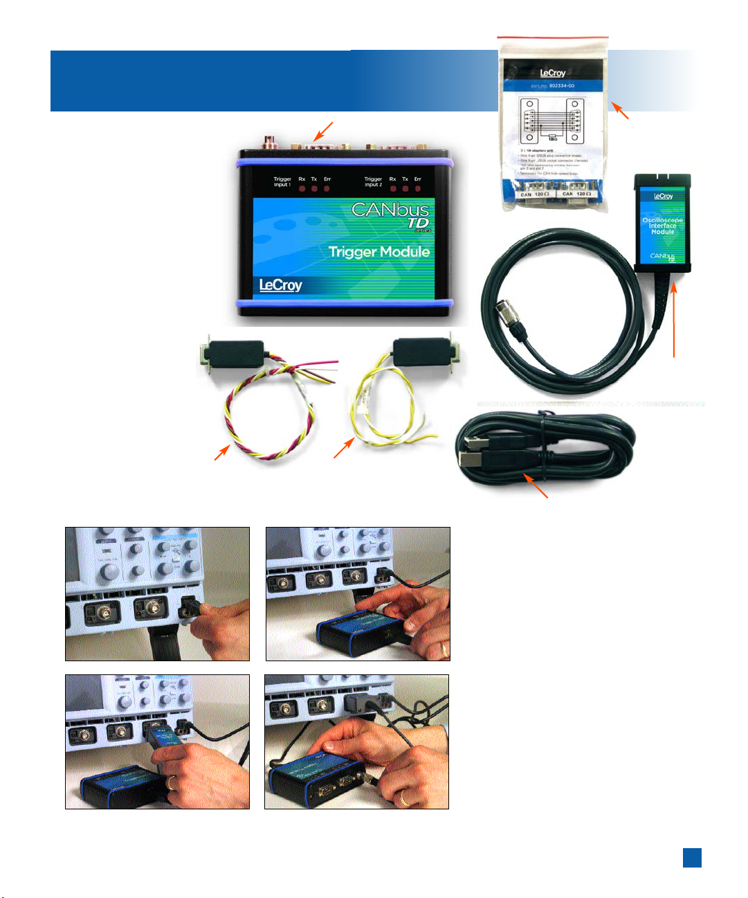
The names of the
hardware components
in CANbus TD are listed
at the right.
Connecting the CANbus TD hardware
to your LeCroy oscilloscope is easy.
Follow these simple steps:
1
Connect the USB cable to one
of the oscilloscope’s USB ports
2
Connect the other end of the
USB2.0 Cable to the CANbus TD
Tri gger Module.
3
Connect the CANbus TD
Oscilloscope Interface Module
(OIM) to the EXT input of
the oscilloscope.
4
Connect the 3-pin plug end
of the OIM to the Trigger Module.
1
First Steps
12
34
CAN Low Speed
and Single-Wire
Connection Cable
CAN High-speed
Connection Cable
Trigger Module
120 Ω
Terminations
Oscilloscope
Interface
Module (OIM)
USB 2.0 Cable
Page 3
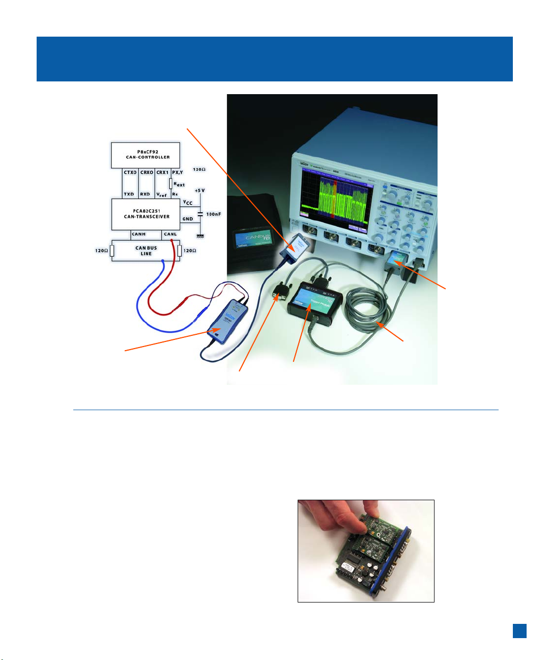
2
Connecting to a CAN Bus Circuit
The CANbus TD Trigger Module operates as a “node”
on the CAN Bus. It contains a Microcontroller, CAN
controller, and Transceiver (Trigger Coupler) and
interfaces to the CAN circuit just like any other
node on the bus. However, the Trigger Module only
provides triggering capability. In order to “view”
the actual CAN physical signal on the oscilloscope
display, you must also probe the CANH and CANL
lines with the included PP007 single-ended probes,
or a differential probe (such as the LeCroy ADP305
or AP033) and input this probe signal(s) to an
oscilloscope channel.
You w ill need to match the Trigger Coupler (Transceiver)
in the Trigger Module to the one on your bus. Trigger
Module has a 251 transceiver pre-installed. It is easy
to install a different Trigger Coupler. Reference the
CANbus TD Operator’s Manual for complete instructions.
Use a differential
probe, or two
single-ended probes,
to view the signal
on the oscilloscope
Plug into any channel
To trigger, connect your own 9-pin to 9-pin
cable to your ECU 9-pin connector,or use a
LeCroy supplied adapter cable
Trigger Module
Trigger Couplers are installed
in the Trigger Module
USB 2.0 Cable
Powers the Trigger Module
and downloads trigger setup
from the oscilloscope
Oscilloscope
Interface Module
Connect to Ext, or a channel
Page 4

All of the normal connection
rules apply when connecting the
CANbus TD Trigger Module to your
bus. The bus must be terminated
correctly,and CANH,CANL, GND,
etc.must be connected to the
right locations. If you don’t
connect to the bus correctly,the
CANbus TD Trigger Module may
generate error frames,may load
down your signal,and will not
trigger. Use your own cable,or a
LeCroy-supplied cable to connect
to your CAN Bus circuit; and
connect your circuit to the Trigger
Module using the 9-pin connector.
It is usually easiest to view the raw
channel input first before setting
up the CAN Trace with a defined
CAN Source. Reference your
oscilloscope’s on-line Help if you
have questions about displaying
a signal on an oscilloscope channel.
After the setup is verified, it is then
a simple matter to turn the channel
OFF and view the CAN Trace,with
decoding (as desired),and any other
non-CAN signals.
3
Connecting to a CAN Bus Circuit
251 1041 1050 1054 5790c 10011S
2 CANL CANL CANL CANL CANL
3 GND VB- VB-
4 100 Ω
(HS Mode)
7 CANH CANH CANH CANH CAN CANH
Notes Connect Connect Connect
120 Ω 120 Ω 120 Ω
between between between
pins 2 + 7 pins 2 + 7 pins 2 + 7
Pin # Transceiver/ Trigger Coupler
Page 5

Overview
CANbus TD trigger and decoding tools are easily
accessible in a variety of ways. The CANbus TD
option adds an additional dialog for CAN triggering
to the existing oscilloscope Trigger dialog, and a
new set of dialogs for setup of the CAN Analysis
and viewable CAN Trace and CAN Zoom. The CAN
|triggering dialog is conveniently accessed with just
one touch of the screen when the CANbus TD Trigger
Module is connected to the oscilloscope. The other
dialogs are always accessible through the Analysis
pull-down menu.
CAN Trigger
When the Trigger Module is completely connected
to the oscilloscope (both the USB cable and OIM are
connected), the CAN Trigger dialog will automatically
be displayed on the oscilloscope display. If you
don’t wish for it to be displayed,you can simply
touch “Clos e” to close the dialog.
CAN Analysis, CAN Trace, CAN Zoom
These dialogs provide the ability to set up the oscilloscope
for protocol decoding of CAN messages,with display
of the protocol data above the signal. They also allow
quick and easy setup and display of the CAN Trace
when you are using either single-ended or differential
probes,and when the source is a channel,a stored
memory (reference waveform) trace, or some other
trace. Zooming of the CAN messages (for more detail)
is also included in these dialogs.
When the Oscilloscope Interface Module (OIM) is
connected to the oscilloscope,a CAN Trace descriptor
box is displayed on the oscilloscope screen. This provides
one touch access to the CAN Trace setup dialog,and
quick access to the CAN Analysis and CAN Zoom dialogs.
Reference the Operator’s Manual for instructions on
how to access these dialogs at any time.
4
Using CANbus TD
CAN Trigger
CAN Analysis,
CAN Trace,
CAN Zoom
Page 6

Error Frame Highlight
and Zooming
When capturing long records
with hundreds or thousands
of CAN messages,only error
frame messages are decoded
on the compacted display.
Error Frames are outlined in red,
and easy to find. To see more
detail,use the (magenta-colored)
CAN Zoom trace.
Zoom Controls
Zooming is easy with LeCroy’s
front panel zoom controls.
Zoom controls are “active”
for the last non-channel
trace turned ON or OFF,or
for whatever trace has been
made active by touching the
descriptor box.
5
Useful Features
Page 7

6
Helpful Hints
Characterize
System
Performance
You can use many
different built-in
oscilloscope tools,such as cursors, measurement
parameters,statistics and histicons to understand
performance of your embedded controller board.
Depending on other options installed in your
oscilloscope,you may also be able to Histogram and
Tre nd measurement parameters. Reference your
Operator’s Manual for more detailed information.
Sequence Mode
Helps Capture
Infrequent Events
Sequence Mode is a powerful
feature that allows you to
trigger and capture CAN Bus
or other events and save them
to acquisition memory with
minimal dead time (< 6 us)
between triggers. This can be
helpful for capturing sensor
data,error frame conditions
or any event where distinct
events are spaced very close
together (spacing is less than
oscilloscope re-arm time),or
very far apart (minutes,hours
or days).
Page 8

CANbus TD Overview
902338-00
8/04
© 2004 by LeCroy Corporation. All rights reserved.
LeCroy,ActiveDSO, ProBus,SMART Trigger, JitterTrack,WavePro,WaveMaster, and Waverunner are registered trademarks of LeCroy Corporation.
Information in this publication supersedes all earlier versions. Specifications subject to change without notice.
Open the CAN Trace setup dialog by touching this
area. Select the source channel for the CAN Trace in
this dialog,and turn the CAN Trace ON/OFF. The
source can also be a memory or a math
function. Also select whether you are using a
single-ended or differential probe.
Tou ch th is area to open the CAN Zoom dialog.
Contr ol the CAN Zoom trace from this dialog,
and turn it ON/OFF.
Descriptor labels allow quick access to dialogs.
Tou ch th em to open the dialog specific to that
descriptor label.
The CAN trigger can be set up from within the
Tri gger dialog. Touch the Trigger descriptor label,
then select the CAN Trigger tab. You can also
access the Trigger dialog from the menu bar.
The Timebase dialog can be used to fix the sample
rate to a specific value. Touch the Timebase descriptor
label to open the dialog. Use a value at least 4x the
bit rate,or the decoding algorithm will not compute.
.
Add cursors to your display by touching this
area and selecting the appropriate cursors.
Adjust cursor position with the front panel knobs.
Or,turn the cursor knobs to turn cursors ON.
Add measurement parameters by touching
this area. Or,touch the MEASURE button in the
toolbar in the CAN Trace and CAN Zoom dialogs.
A descriptor label with a different color
background indicates that this trace is “Active”.
If it is a CAN Zoom,Memory,or Math Trace,
and is “Active”, the front panel zoom controls
will zoom and position that particular trace.
Escape from the CANbus TD program at any
time to add math,measurement parameters,
or to make changes to your setup. Re-enter
through Analysis,or by touching the CAN Trace
or CAN Zoom descriptor labels below the grid.
1
1
2
2
3
4
5
6
7
9
9
9
9
Sales and Service
Throughout the World
Corporate Headquarters
700 Chestnut Ridge Road
Chestnut Ridge, NY 10977
USA
www.lecroy.com
LeCroy Sales Offices:
China: B eijing
Phone (86) 10 8526 1618
Fax (86) 10 8526 1619
France: Les Ulis
Phone (33) 1 6918 8320
Fax (33) 1 6907 4042
Germany: Heidelberg
Phone (49) 6221 827 00
Fax (49) 6221 834 655
Hong Kong
Phone (852) 2834 5630
Fax (852) 2834 9893
Italy: Venice
Phone (39) 041 599 7011
Fax (39) 041 456 9542
Japan: Osaka
Phone (81) 6 6396 0961
Fax (81) 6 6396 0962
Japan: Tokyo
Phone (81) 3 3376 9400
Fax (81) 3 3376 9587
Korea: S eoul
Phone (82) 2 3452 0400
Fax (82) 2 3452 0490
Singapore
Phone (65) 6442 4880
Fax (65) 6442 7811
Sweden: Stockholm
Phone (46) 8 580 143 45
Fax (46) 8 580 143 45
Switzerland: Geneva
Phone (41) 22 719 2228 (North)
Phone (41) 22 719 2175
(South)
Fax (41) 22 719 2230
U.K.: Abingdon
Phone (44) 1 235 536 973
Fax (44) 1 235 528 796
U.S.A.: Chestnut Ridge
Phone (1) 845 578 6020
Fax (1) 845 578 5985
4
6
4
5
8
7
8
3
This is an analog signal that is
time-correlated with the CAN Trace.
This is the CAN Zoom Trace
This is the CAN Trace capture
 Loading...