

Teledyne BVS-SP-1280M-IDE, BVS-SP-0640M-IDS, BVS-SP-0640M-IDE, BVS-SP-1280M-IDS Quick Start Manual
BOA Spot ID
Quick Start Guide
BOA Spot ID Quick Start
1
Ver sion 1.2; 2017-11-20

Notice
BOA Spot ID Quick Start Guide
Document Number 405-00064-00
Copyright © 2016 Teledyne DALSA Incorpor ated.
All rights reser ved.
All copyrights in this manual, and the hardware and software described in it, are the
exclusive property of Teledyne DALSA Incorporated and its licensors.
Claim of copyright does not imply waiver of Teledyne DALSA Incorporated or its licensors
other rights in the work. See the following Notice of Proprietary Rights.
NOTICE OF PROPRIETAR Y RIGHTS
This manual and the related hardware and software are confidential trade secrets and the
property of Teledyne DALSA Incorporated and its licensors. Use, examination,
reproduction, copying, transfer and/or disclosure to others of all or any part of this manual
and the related documentation are prohibited except with the express written consent of
Teledyne DALSA Incorporated.
The information in this document is subject to change without notice. Teledyne DALSA
Incorporated makes no representations or warranties with respect to the contents of this
manual and specifically disclaims any implied warranties of merchantability or fitness for a
particular purpose. Teledyne DALSA Incorporated assumes no responsibility for errors or
omissions in this document.
Teledy ne DALSA logo is a trademark of Tel edyne DALSA Incorporat ed. All other
trademarks ar e the pr oper ty of their respective owners.
Teledy ne DALSA Industrial Products
Information: info.ipd@teledyne.com
Support: support.ipd@teledyne.com
Web: http://www.teledynedalsa.com/visionsystems
700 Technolo gy Park Drive
Billerica, MA, USA 01821
Tel 1.978.670.2002 Fax 1.978.670.2010
2
Ver sion 1.2; 2017-11-20 BOA Spot ID Quick Start

Certifications
Declaration of Conformity
Manufacturer Teledyne DALSA Industrial Products Incorporated
CE We declare that this product has been tested to comply with the
FCC We declare that this product has been tested and found to
700 Technology Park Drive
Billerica MA 01867
USA
EC Directive for a class A digital device in accordance with
EN55022/CISPR22.
comply with the limits for a class A digital device, pursuant to
Part 15 of the FCC rules. These limits are designed to provide
reasonable protection against harmful interference in a
residential installation.
This equipment generates, uses and can radiate radio frequency
energy and may cause harmful interference to radio
communication.
Other Certifications
IP67 This product meets the requirements for industrial applications
that require IP67 wash down protection - requires fitted sealing
lens cover and sealing plugs on unused connectors.
CFR 21 Part 11 This product provides the tools needed for users to implement
an auditing program that could be in compliance with CFR 21
Part 11. These tools include:
• System or software backup and restore
• System software security (password login and access limits)
• Protection of system backup files from modification.
• Time stamp information on data output.
3
Ver sion 1.2; 2017-11-20 BOA Spot ID Quick Start

Handling Precautions
Care should alway s be exer cised w hen handling and operati ng y our BOA Spot Vision
Sensor . Even though the system is encased wi thi n a rugged, industrial enclosure,
incorrect use or handling can resul t i n damag e to your investment. To prevent this, we
recommend follow ing these pr ecaution s:
• Do not look directly into the LED ring light during operati on! The light is extremely
bright and may cause pain or damage y our vision.
• Avoid “hot-pl ug g i ng ” cables and dev ice s. Always shut the system down and r emov e
power before connecting or disconnecting anything to it.
• Do not use in a Free-standing operation. Mount the B OA Spot properly to prevent it
from falling accidentall y. Mounting holes are provided on each side of the BOA Spot.
• Always use the BOA Spot sensor w ithin its recommended operati ng condit ions.
Refer to the complete specifications on page 25.
• Do not install BOA Spot in a loca ti on that will expose i t to excessive heat, humidity,
vibration, impact, corrosive substances, flammable substances, static electricity or
Electro Static Discharg e (ESD ).
• Never expose the internal electr onics by opening the enclosure.
• Do not attempt to modify the BOA Spot or open the case. This unit has no fiel dreplaceable co mponents ( beyond repl acing the Lens or Ring-lig ht). Tamper ing wi th
the unit will void the product war ranty.
Warranty
Teledy ne D ALSA warr ants the BOA Spot Vision Sensor ag ainst defects in material s and
workmanship for a period of twenty four (24) months from the date of delivery. T eledy ne
DALSA and its representatives expressl y disclaim any and all other warranties.
Your sole remedy shall be repair or replacement of the BOA Spot Vision Sensor pr oduct
and associated optional co mponents, pr ovided t hat the defective product is returned
within the warranty period.
If you need to return the BOA Spot Vision Sensor, you must co ntact the Teledyne DALSA
representative w ho sold y ou the product. Do not return your product to Teledyne DALSA
without prior authoriz ation.
Teledy ne DALSA assumes no li abi l it y for damag es resulting from the use of thi s manual.
4
Ver sion 1.2; 2017-11-20 BOA Spot ID Quick Start

Table Of Contents
Introduction Product Overview …………………….......................... 6
Code Reading Considerations …………………….......................... 7
Code Variability …………………….......................... 8
Inspection Capabilities …………………….......................... 9
Components …………………….......................... 10
Lens, Cover & Light Options …………………….......................... 11
FOV and Reading Distances …………………….......................... 12
Installation Connections & Pin-outs …………………….......................... 17
Cable Configurations …………………….......................... 19
Mounting Options …………………….......................... 22
Dimensional Drawings …………………….......................... 23
Specifications General Specifications …………………….......................... 25
Input Specifications …………………….......................... 26
Output Specifications ……………………......................... 28
PL-101 Specifications ………………………………………. 30
PL-101 Wiring Diagrams ………………………………………. 31
Serial Port Connection ………………………………………. 32
Software Setup How to Access BOA Spot …………………….......................... 33
Configure Client PC …………………….......................... 34
Configure BOA Spot ………………………………………. 38
iDiscover Utilit y …………………….......................... 39
BOA Spot Web Server …………………….......................... 40
Firmware Upgrading …………………….......................... 41
Application Settings …………………….......................... 42
Application Interface ………………………………………. 43
Getting Started ………………………………………. 44
Emulator Software Complementary Programs ……………………………………… 51
Troubleshooting Common Startup Issues ……………………..........................
..
5
Ver sion 1.2; 2017-11-20 BOA Spot ID Quick Start
53
Introduction
BOA Spot ID Overview
BOA Spot is a fully integrated vision sensor t hat has been designed for i ndustr i al ID
(Barcode, 2D Matrix and T ext ) applications. Packaged complete w ith application
software, BOA Spot ID offers a robust, easy-to-deploy fixed code reader and inspection
tool for the factory floor . BOA Spot is compatible w ith Windows 7, 8.1 and 10. BOA Spot
is not compatible with Windows XP.
BOA Spot Vision Sensor s are rugged dev i ces that can be integrated into existing
production l ines, mach iner y or moving equi pment. They are su ppor ted by standard
industrial M 12 cables to further simpl ify and r educe i mplementat ion cost s.
Rated for IP67 deployment w hen fitted w ith the M12 lens and lens cov er, BOA Spot
vision sensors can be mounted in w ash down factory envir onments w it hout the need for
additional protect iv e enclosures. The product is also available w ith a C-mount lens
option for greater imag e quali ty, operating distance and li ghti ng flexi bili ty.
BOA Spot ID Models
• BVS-SP-0640M-IDS-XXX-Y – 640x480 senso r w ith standard reader tools
• BVS-SP-1280M-IDS-XXX-Y – 1280x960 senso r with standard reader tools
• BVS-SP-0640M-IDE-XXX-Y – 640x480 sensor with expanded tool set
• BVS-SP-1280M-IDE-XXX-Y – 1280x960 sensor wi th expanded tool set
In addition to reading barcodes, the IDE model offers advanced capabilities for reading
printed tex t, veri fyi ng the posi ti on and content of labels, or verifying the presence,
absence and integrity of features on parts.
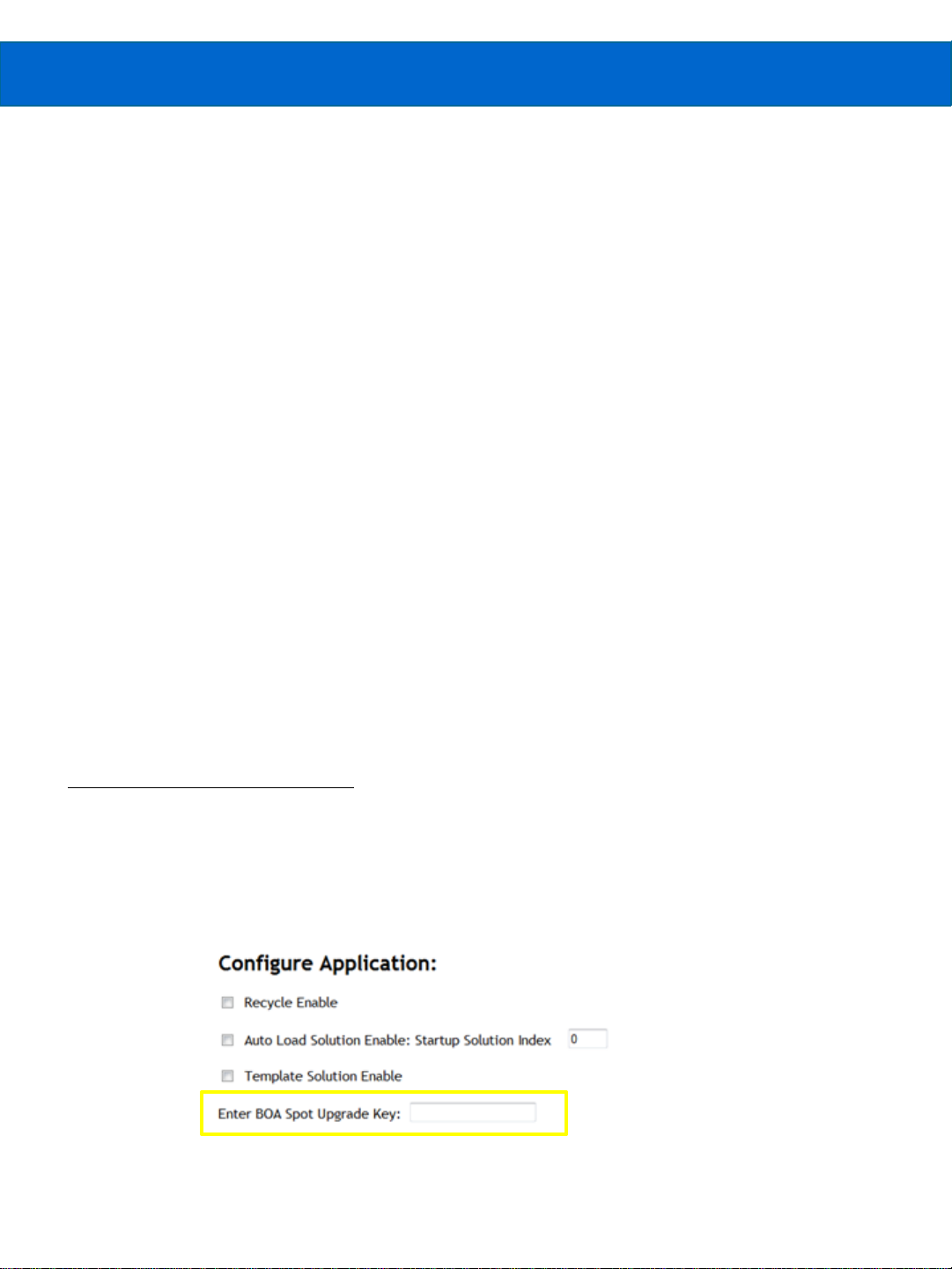
Upgrading from IDS to the IDE:
The IDS model can be field upgraded vi a a license to support the IDE advanced
features. The upgr ade can be purch ased t hrough our local r eseller and w ill require
sending the serial number and MAC ID of the device. The upgrade license is entered in
the highlighted field on the Applicati ons page of the w eb se r v er (as shown below). More
information on this is provided later in this document.
6
Ver sion 1.2; 2017-11-20 BOA Spot ID Quick Start

Code Reading Considerations
BOA Spot ID offers fast decoding of 1D and 2D codes pri nted or directly marked on a
variety of surfaces, including paper, plast ic and metal. The decoder is robust and able
to read poorly printed, w orn or environmenta lly degr aded codes i n any orientation .
Guidelines for reliable code reading are as follows:
1D Codes
• M ini mum distance between bars = 1.5 pixel s (2.5 pi x el s for low contrast)
• M ini mum bar width = 1.5 pixel s ( 2.5 pi xels for low contrast)
2D Codes
• M ini mum cell size = 2 x 2 pixels
• M ini mum dot diameter = 2 pix el s
All Codes
• Non-DPM = Maximum ROI size = 1280 x 960
• D PM = Maximum ROI area = 614,400 pix els (i .e. 1280 x 480, 1024 x 600, 960 x 640,
800 x 768 and anything smaller, such as 640 x 480)
• U se “Invert” preprocessor to decode light-on-dark barcodes
• With the excepti on of “low contrast”, the control parameters descr ibed on the next
page are mutually exclusive. Onl y one can be enabl ed at a time.
General deployment guidel ines:
• Choose a lens that satisfies the FOV and minimum bar/module size
• Adjust wor ki ng distance to maximize the code FOV wher ever possible
• BOA Spot ID with integrated lig ht is a good choice for high contr ast codes pr inted on
non-reflective surfaces
• BOA Spot ID with external dar k field li ght is better for dot peen codes
• BOA Spot ID with external di ffuse of f-axi s l i g ht is better for cur ved or highly reflective
surfaces.
• Increase li g ht and r educe shutter time to stop motion for fast moving applicati on s
7
Ver sion 1.2; 2017-11-20 BOA Spot ID Quick Start

Compensating for Code Variability
Control Parameter Model Description
Low Contrast IDS/IDE
Enable decoding of low contrast 1D codes (D-on-L or Lon-D) with a minimum module size of 2.5 pixels.
Enhance Contrast IDS/IDE
Enable contrast enhancement preprocessor to
improve readability of 1D or 2D.
1D Security Level IDS/IDE
Helps improve 1D decoding when print quality is poor
or module size is marginal.
Basi c Etch IDS/IDE
Enable decoding of basic laser/chemical etch DPM
codes
Basi c Dots IDS/IDE
Enable decoding of basic dots DPM codes, including
inkjet marks.
Basi c Inkjet IDS/IDE
Enable decoding of poor quality inkjet DPM codes.
Basi c Perspective IDS/IDE
Enables decoding of good quality, centered codes
with severe perspective distortion
Dot peen D-on-L IDE
Enables robust algorithm for decoding dark on light
dot peened codes
Dot peen L-on-D IDE
Enables robust algorithm for decoding light on dark
dot peened codes
Laser & Chemical Etch IDE
Enables robust algorithm for decoding laser and
chemi cally etched codes
DPM Ti m e out IDE
Total time in ms that the advanced algorithm is
allowed to run. A value "0" indicates no timeout
The variability between surface type and printing method can result in significant
changes in code appearance from par t to part. The IDS and IDE models includes imag e
filters and contr ol par ameter s to enhance readabi li ty for poor print q ual i ty or direct part
marking (DPM). The IDE model also includes advanced algor ithms speci fically
designed for challenging DPM applications.
8
Ver sion 1.2; 2017-11-20 BOA Spot ID Quick Start

BOA Spot ID Inspection Capabilities
The following table shows the tools available in the IDS & IDE models. Detailed
information about each of the tools is avail able in the on-line help.
Icon Tool Description Model
Use to decode: Code 11, 32, 39, 93, 128,
Barcode
IDS & IDE
I25, UPC-A/E, EAN-8/13, Databar,
BC412, Pharmacode and more
2D Matrix
Count
Point
Preprocessor
Edge Count
Verify
OCR
Graphics
Match
IDS & IDE
IDS & IDE
IDS & IDE
IDS & IDE
IDE
IDE
IDE
IDE
IDE
Use to decode: Data matrix, QR Code,
PDF417, MicroPDF and more
Use to count characters or features on a
label or part.
Use to detect a single edge point for
position measurement or as a locator for
aligning other tools
Use to enhance picture qual ity to
accentuate features of interest.
Use to find or count edge transitions for
determining label position and or
alignment
Use to verify product features, such as
labels or logos. Trains on a series of good
samples to learn acceptable variation.
Use to read printed, stamped or etched
characters on labels or parts.
Use to add text or draw shapes, to label or
highlight tool result s or features in the
image area
Use to train and match features for
inspection or tool alignment. Supports
multiple matches and 360° orientation.
9
Ver sion 1.2; 2017-11-20 BOA Spot ID Quick Start

BOA Spot Components
BOA Spot V isi on Sensors are shipped w ith the components li sted below. Take a few
moments to veri fy that ev er y t hing has arrived in good co ndit ion. If your product has
been visibly damaged during shipment or is missing parts, please contact your Teledyne
DALSA representative i mmediately.
Standard componen ts (ship w it h ever y BOA Spot Vision Sensor):
Component Description
BOA Spot Sensor
BVS-SP-0640M-IDL-TFF-C
BVS-SP-1280M-IDL-TFF-C
Mounting Screw Kit M4 screws for mounting the BOA Spot (Qty 4)
* Lens and ring-light are only specified for the M12 version, not available with C Mount lens.
BOA Spot Fully integrated vision system with 640x480 or 1280x960
monochrome sensor, lens, processing engine, embedded software,
communications and light control.
(L= feature level: S or E); (T = lens type: M= M12, C=C Mount);
(FF* = focal length in mm: 06, 08, 12, 16); (C= Ring-Light Color:
R=red, B=blue, W=white*)
Optional components (sold separately) :
Component Description
Cables
A-BVS-E8S-X
A-BVS2-IO12S-X
BVS-PL-101
A-BVS-PL101S-X
BVS-PL-100 Panel Link breakout module for Passive Power on Ethernet
M12-RJ45 Ethernet cordset (X= length: 5=5 m, 10=10 m)
M12 single-ended IO cordset (X= length: 5=5 m, 10=10 m)
Panel Link breakout module. Provides convenient panel access to
BOA Spot I/O and serial port
M12 IO cordset to PL-101 (X= length: 5=5 m, 10=10 m)
A-BVS-SP-LCG-45 Lens Cover for C Mount lens option. Required for IP67 compliance.
(45 mm internal lens length)
A-BVS-M12-P M12 plug for IP67 compliance
A-BVS-SP-M12-LKIT M12 lens kit (includes 6, 8, 12 & 16 mm lenses)
Lights Various Lighting options available from Teledyne DALSA
Filters Various C-Mount filters available from Teledyne DALSA
10
Ver sion 1.2; 2017-11-20 BOA Spot ID Quick Start
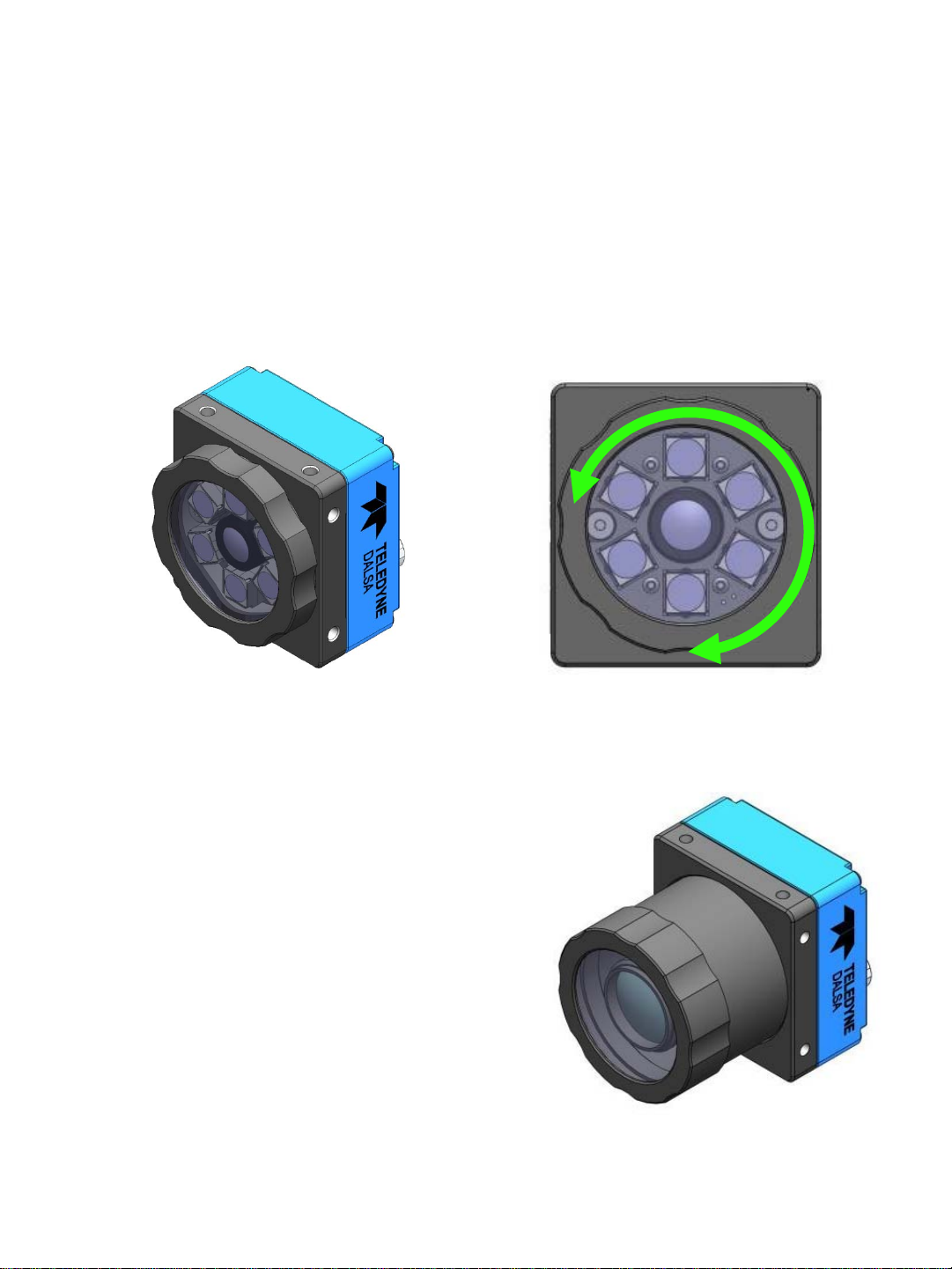
Lens, Cover, and Light Options
M12 Lens
The BOA Spot Vi sion Sensor can be ordered w ith an M12 lens in several focal leng ths
(6, 8, 12, 16 mm). The M12 option comes with a special IP67 cover, that allows you to
change focus wi thout removi ng the cov er.
The M12 Lens and cover support an LED ring-light that is mounted inside the cover.
The ring-light is availabl e in White, Red, or Blue and specified at time of order.
C-Mount Lens
The BOA Spot Vision Senso r can be ordered
with support for a C-Mount lens. Lenses are sold
separately.
There is an optional IP67 Lens cov er that may be
ordered separately.
There is no internal light option with the C-Mount
lens.
Optional filter s ca n be or der ed separately for use
with the C-Mount lens.
11
M12 cover rotates to adjust focus M12 Lens, Cover, and LED ring
C-Mount Lens
shown with Optional Cover
Ver sion 1.2; 2017-11-20 BOA Spot ID Quick Start
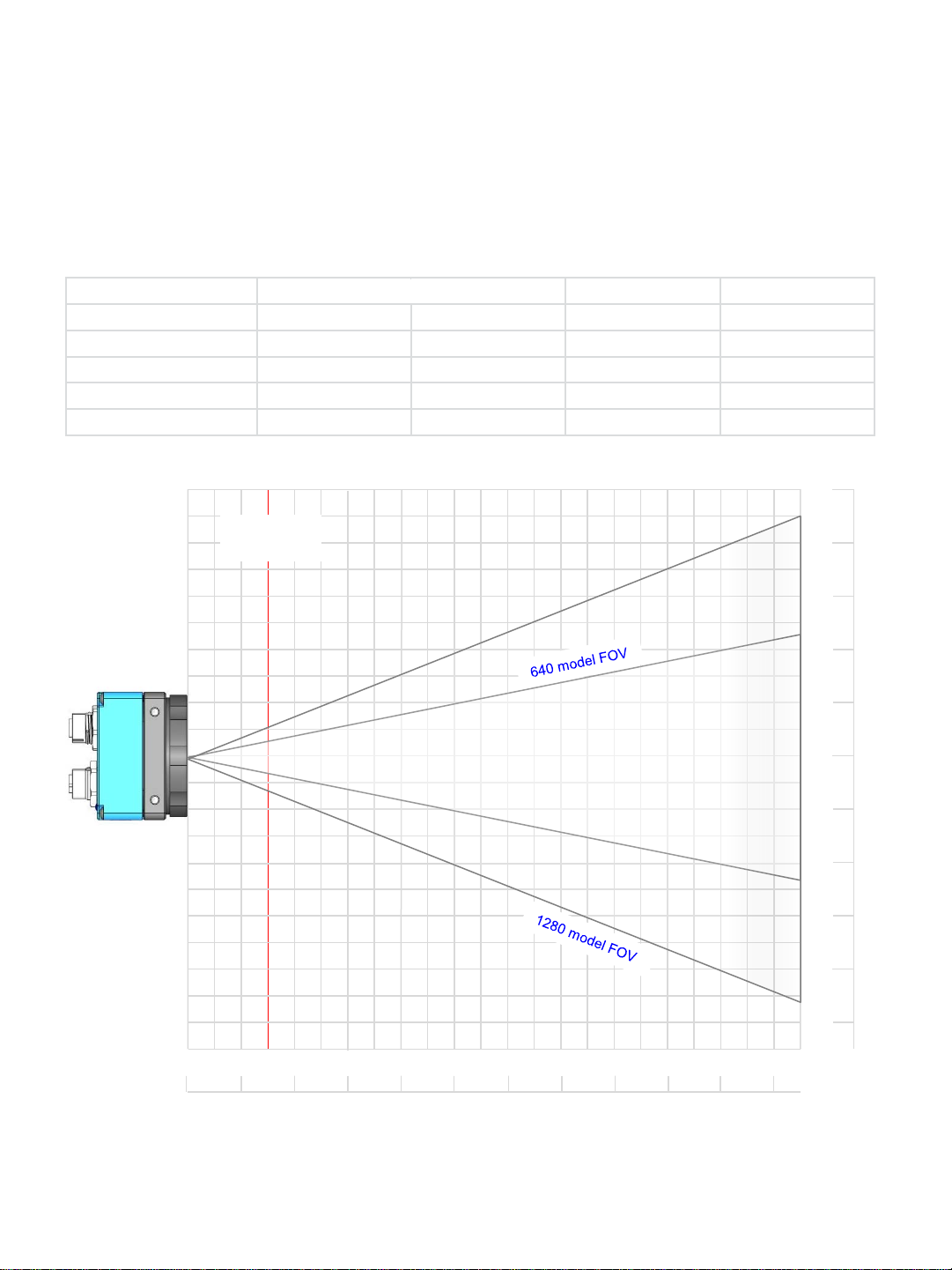
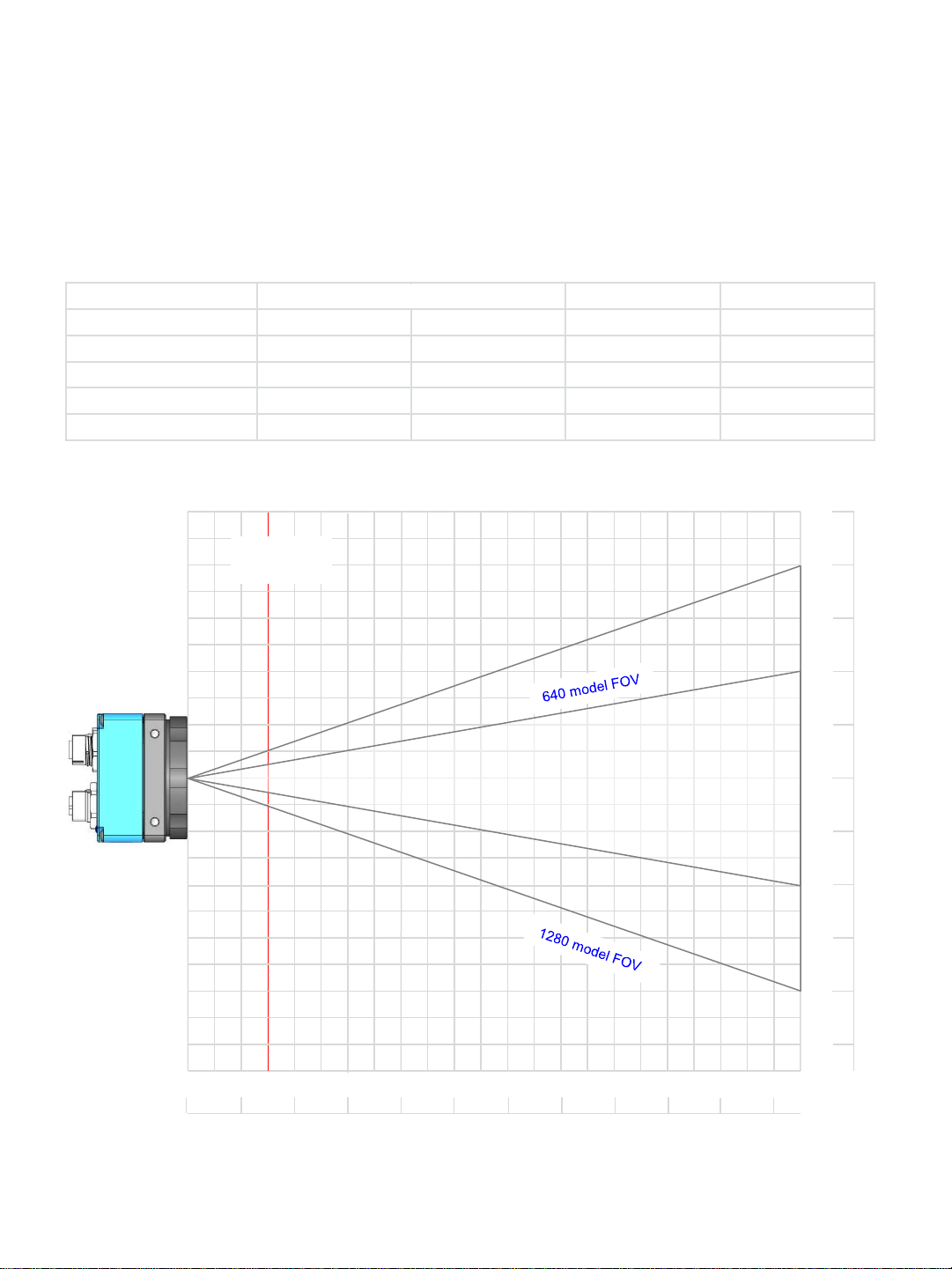
Field Of View (FOV) and reading Distances
Distance in mm 2D min cell (mil) 1D min bar (mil)
640 Model 1280 Model
65 25 x 19 50 x 38 3 2.5
82 32 x 24 64 x 48 4 3
103 40 x 30 80 x 60 5 4
205 81 x 61 162 x 122 10 7.5
Approx FOV (mm)
6 mm Lens
The following table show s the field of view (FOV) widths of the 6 mm lens focused to
205 mm at various working distances for the M640 & M1280 model sensors.
100
Min Focus
Distance
60 80
40
mm
20
0
40 60
80
100
120
140
160
180
200
220
12
Ver sion 1.2; 2017-11-20 BOA Spot ID Quick Start
0
80 60 40 20 20
100
mm
Field Of View (FOV) and reading Distances
Distance in mm 2D min cell (mil) 1D min bar (mil)
640 Model 1280 Model
50 16 x 12 32 x 24 2 1.5
103 32 x 24 64 x 48 4 3
210 40 x 30 80 x 60 5 4
415 80 x 60 160 x 120 10 7.5
Approx FOV (mm)
8 mm Lens
The following table show s the field of view (FOV) widths of the 8 mm lens focused to
415 mm at various working distances for the M640 & M1280 model sensors.
100
Min Focus
Distance
60 80
20
0
mm
60 100
140
160
200
240
280
320
360
400
13
Ver sion 1.2; 2017-11-20 BOA Spot ID Quick Start
40
0
80 60 40 20 20
100
mm

Field Of View (FOV) and reading Distances
Distance in mm 2D min cell (mil) 1D min bar (mil)
640 Model 1280 Model
90 16 x 12 32 24 2 1.5
130 24 x 18 48 x 36 3 2.5
170 32 x 24 64 x 48 4 3
210 40 x 30 80 x 60 5 4
410 80 x 60 160 x 120 10 7.5
Approx FOV (mm)
12 mm Lens
The following table show s the field of view (FOV) widths of the 12 mm lens focused to
410 mm at various working distances for the M640 & M1280 model sensors.
100
Min Focus
Distance
60 80
40
0
mm
80 120
160
200
240
280
320
360
400
440
14
Ver sion 1.2; 2017-11-20 BOA Spot ID Quick Start
40
0
80 60 40 20 20
100
mm

Field Of View (FOV) and reading Distances
Distance in mm 2D min cell (mil) 1D min bar (mil)
640 Model 1280 Model
120 16 x 12 32 x 24 2 1.5
225 32 x 24 64 x 48 4 3
280 40 x 30 80 x 60 5 4
550 80 x 60 160 x 120 10 7.5
Approx FOV (mm)
16 mm Lens
The following table show s the field of view (FOV) widths of the 16 mm lens focused to
550 mm at various working distances for the M640 & M1280 model sensors.
100
Min Focus
Distance
60 80
40
mm
50
0
100 150
200
250
300
350
400
450
500
550
15
Ver sion 1.2; 2017-11-20 BOA Spot ID Quick Start
0
80 60 40 20 20
100
mm

Product Support
In addition to this Qui ck Star t G uide, the foll owing information is available:
1. On-line help: Finger tip help i s availabl e on ev ery screen (panel) of the BOA Spot
Software User Interface.
2. Additional manuals and documentation are included on the CD that ships with the
product.
3. Factory support is availabl e by email at: support.ipd@teledyne.com.
4. Call, fax or email your local representati ve w ho sold y ou the product.
16
Ver sion 1.2; 2017-11-20 BOA Spot ID Quick Start
Installation
Connecting the BOA Spot Vision Sensor
This section details how to connect the BOA Spot Vision Sensor w ith its associated
components and factory environment.
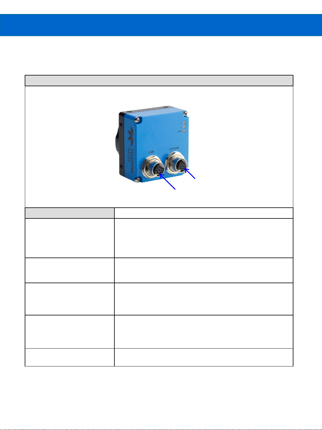
Camera Connectors and Indicators
I/O PWR 12 Pin
LAN 8 Pin
Definitions Designator
LAN
I/O PWR
LED 1 Blue Solid = Sensor booted, not configured (no Solution file)
LED 2 Blue blink = Booting (should stop after 20 seconds)
LED LAN Blue = Warm reset or reboot
10/100 BaseT Ethernet connection. Provides the primary
interface for configuring the sensor, developing the application
and monitoring results.
Note: The BOA Spot can be powered from the Ethernet cable
directly (Passive Power over Ethernet or PPoE).
Provides access to the sensor I/O – 3 IN, 3 OUT, RS-232. Also
provides PWR input (24-30V). Note: The power is common to
both connectors.
Green Solid = Solution loaded, ready to run
Green blink = Solution loaded & running, acquisition in process
Red = Sensor Fault
Green = Inspection Pass (runtime decision result)
Blue = Inspection Recycle (runtime decision result)
Red = Inspection Fail (runtime decision result)
Red/Green/Yellow = Network activity
NOTE: The BOA Spot does not support the IEEE 802.3af standar d Pow er over Etherne t
(PoE) and should not be directly connected to a PoE supported rout er.
17
Ver sion 1.2; 2017-11-20 BOA Spot ID Quick Start
 Loading...