

Teledyne BV3200 User Manual
User’s Manual
BV3200 Pole Mount
Part Number: 204765-00
Revision: A, October 2014
© 2014 Teledyne BlueView Technologies, Inc. All rights reserved.
All product names are trademarks of their respective companies.
Page | 0

Table of Contents
Chapter 1: Important Safeguards ....................................................................................... 2
Chapter 2: System Components ........................................................................................ 3
System Contents ........................................................................................................ 3
System Overview ....................................................................................................... 4
Chapter 3: Setup & Operation ........................................................................................... 5
Assemble the Pole ...................................................................................................... 5
Tilt Angle Adjustment................................................................................................... 7
Pole Mounting ........................................................................................................... 7
Junction Box ............................................................................................................. 8
Installing the Junction Box ............................................................................................ 9
Final Cable Connections ............................................................................................ 11
Install ProViewer 4 Software ........................................................................................ 11
Configure PC .......................................................................................................... 12
Connecting the BV3200 GPS in ProViewer 4 .................................................................... 12
Sonar Angle ........................................................................................................... 15
ProMapper Add-On Software ....................................................................................... 16
GPS Heading/Compass Calibration ............................................................................... 16
System Breakdown ................................................................................................... 17
Chapter 4: Maintenance ................................................................................................ 18
Before Use ............................................................................................................. 18
After Use ............................................................................................................... 18
Chapter 5: Troubleshooting ............................................................................................ 19
Still not working? ...................................................................................................... 20
Appendix A: Technical Specifications ................................................................................ 21
Appendix B: Connector Pinouts ....................................................................................... 22
Page | 1

Teledyne BlueView, Inc. has made every effort to ensure the accuracy and
completeness of this document; however, because ongoing development efforts are
made to continually improve the capabilities of our products, we cannot guarantee the
accuracy of the contents of this document. We disclaim liability for errors, omissions, or
future changes herein.
©2014 Teledyne BlueView, Inc. All rights reserved. No part of this publication may be
copied, reproduced, or translated, without the prior written consent of Teledyne
BlueView, Inc. No part of this publication may be stored or transmitted in any electronic
form without the prior consent of Teledyne BlueView, Inc. Any unauthorized use is a
violation of copyright laws.
Warning! This device should not be used as a navigational aid to prevent collision,
grounding, boat damage, or personal injury.
Warning! This product contains lead, a chemical known to the state of California to
cause cancer, birth defects and other reproductive harm. Handling and/or opening this
unit may result in exposure to lead, in the form of solder.
Warning! Disassembly and repair of this electronic unit should only be performed by
authorized service personnel. Any modification of the serial number or attempt to repair
the original equipment or accessories by unauthorized individuals will void the warranty.
Warning! Changes or modifications to this unit not expressly approved by the party
responsible for compliance may void the user’s authority to operate this equipment.
Warning! This equipment contains High Voltage electronics. Tampering with or using
damaged equipment could lead to serious injury.
Warranty Information:
The BV3200 is backed by a standard 12-month parts and labor warranty policy. Seller’s
terms and conditions of sale can be found at www.blueview.com
For more information on safety and/or maintenance issues please call Teledyne
BlueView, Inc. at 425.492.7376.
Page | 1

Chapter 1: Important Safeguards
To reduce the risk of electrocution:
Always unplug the BV3200 control box immediately after using. Do not place or store the control box
where it can easily fall or be pulled into water. If the box does fall in the water, unplug before retrieving.
WARNING – To reduce the risk of burns, electrocution, fire, or injury to persons:
1. Use this BV3200 and sonar only for its intended use as described in this manual. Do not use
attachments not recommended by BlueView Technologies.
2. Never operate this product if it has a damaged cord or plug, if it is not working properly, if it has
been dropped or damaged, or if the control box has been dropped into water.
3. Keep cords away from heated surfaces.
4. Connect this product to a properly grounded outlet only. See grounding instructions.
This product should be grounded. In the event of an electrical short circuit, grounding reduces the risk of
electric shock by providing an escape wire for the electric current. The BV3200 control box is equipped
with a cord having a grounding wire with a grounding plug. The plug must be plugged into an outlet that is
properly installed and grounded.
If repair or replacement of the cord or plug is necessary, do not connect the grounding wire to either flat
blade terminal. The wire with insulation having an outer surface that is green with or without yellow stripes
is the grounding wire.
Check with a qualified electrician or serviceman if the grounding instructions are not completely
understood, or if in doubt as to whether the product is properly grounded.
This product is factory equipped with a specific electric cord and plug to permit connection to a proper
electric circuit. Make sure that the product is connected to an outlet having the same configuration as the
plug. No adapter should be used with this product. Do not modify the plug provided—if it will not fit the
outlet, have the proper outlet installed by a qualified electrician. If the product must be reconnected for
use on a different type of electric circuit, the reconnection should be made by qualified service personnel.
If it is necessary to use an extension cord, use only a three wire extension cord that has a three-blade
grounding plug, and a three-slot receptacle that will accept the plug on the product. Replace or repair a
damaged cord.
Page | 2

Chapter 2: System Components
BV3200 Transport Case
Pole Assembly
Junction Box
Pole Mount
7 Ft Ethernet Cable
USB Cable
Power Cable
BV3200 Software and Manuals CD Containing:
- BV3200 QuickStart Guide
- BV3200 User’s Manual
- ProViewer 4 Software
- ProViewer 4 Handbook
- USB Serial Adapter Driver Software
Hex Driver
Screw Kit
Printed BV3200 QuickStart Guide
System Contents
You will receive an accessory kit containing the following:
Page | 3
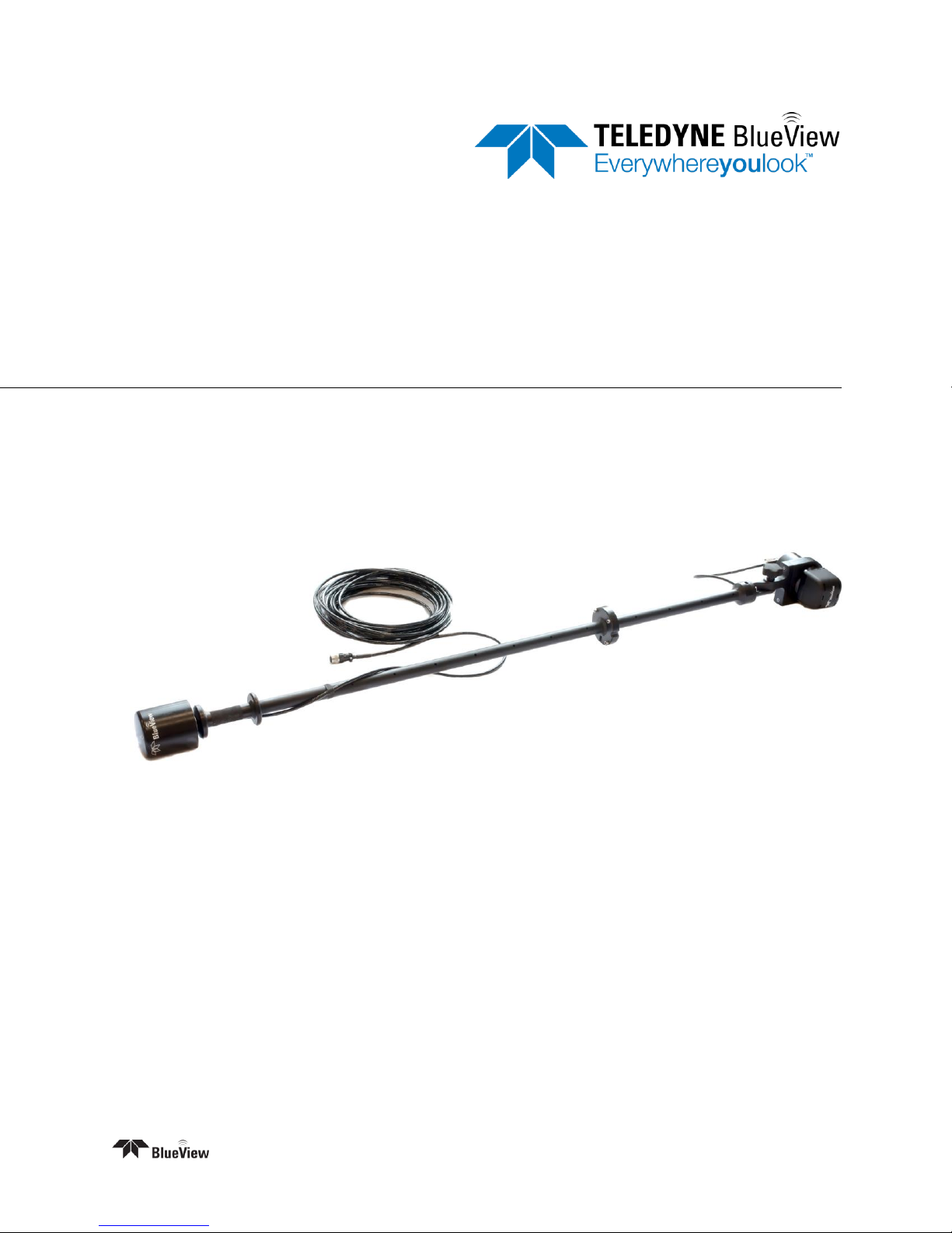
System Overview
The BlueView BV3200 Mobile Acoustic Underwater Vision® System consists of a boat mountable
BlueView sonar with an adjustable tilt angle, integrated GPS and a compass. The entire system connects
through a single cable to the Junction Box, which then connects to a PC via USB and Ethernet. The
BV3200 system is airline checkable luggage.
To familiarize yourself with the BV3200 system, please review the information in this manual.
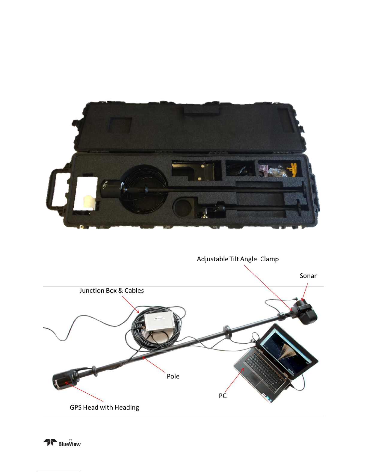
BV3200 unit in travel case
Page | 4
BV3200 Components
Chapter 3: Setup & Operation
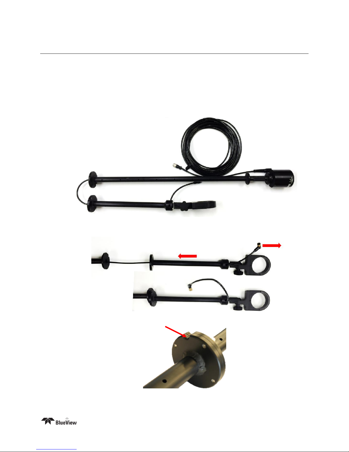
Assemble the Pole
After verifying that all necessary components are present, you are ready to begin assembly of the
BV3200.
The following instructions will walk you through all steps necessary to assemble the pole, mount the
sonar, and connect all required cabling.
1. Remove the BV3200 pole unit from case.
2. Place the top and bottom pole pieces end to end. Pull the sonar cable through the pole as you
bring the pole bolt flanges together.
3. Rotate one of the pole segments till the alignment notches are adjacent to each other.
Page | 5
4. Attach the lower section to the upper using the provided cap screws. Insert the bolt first through
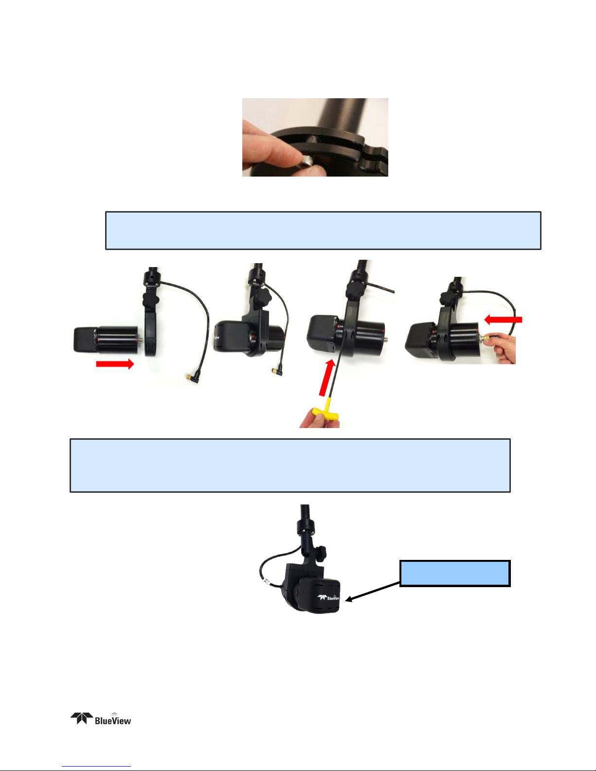
NOTE: The sonar is inserted into the clamp such that its connector is on the same side
as the Sonar Cable.
NOTE: Use the stickers and connector placement on the rear end cap of the sonar or the
logo on the front end of the sonar to determine the up-down orientation of the sonar. If the
sonar is inverted, be sure to select the “inverted” option in ProViewer’s settings.
Logo facing up
the unthreaded upper flange and screw into the threaded lower flange.
5. Attach the sonar to the sonar clamp by loosening the four cap screws, sliding in the sonar and
retightening the four cap screws.
6. Connect the sonar cable to the sonar connector.
Page | 6
 Loading...