

Teledyne BOA Pro, Dalsa BOA Pro, Dalsa BVS-1280M-PRO Installation Manual
BOA Pro
Smart Vision System
Installation Manual
Version 02
teledynedalsa.com/ipd 1

Notice
BOA Pro Vision System Installation Manual
Document Number 405-00031-00
Revision: 02
Copyright © 2012 Teledyne DALSA, Inc.
All rights reserved.
All copyrights in this manual, and the hardware and software described in it, are the
exclusive property of Teledyne DALSA, Inc. and its licensors.
Claim of copyright does not imply waiver of Teledyne DALSA, Inc. or its licensors
other rights in the work. See the following Notice of Proprietary Rights.
NOTICE OF PROPRIETARY RIGHTS
This manual and the related hardware and software are confidential trade secrets
and the property of Teledyne DALSA, Inc. and its licensors. Use, examination,
reproduction, copying, transfer and/or disclosure to others of all or any part of this
manual and the related documentation are prohibited except with the express
written consent of Teledyne DALSA, Inc.
The information in this document is subject to change without notice. Teledyne
DALSA, Inc. makes no representations or warranties with respect to the contents of
this manual and specifically disclaims any implied warranties of merchantability or
fitness for a particular purpose. Teledyne DALSA, Inc. assumes no responsibility
for errors or omissions in this document.
iNspect, Sherlock, and the Teledyne DALSA logo are trademarks of Teledyne
DALSA, Inc. All other trademarks are the property of their respective owners.
Teledyne DALSA Industrial Products
Information: info.ipd@teledynedalsa.com
Support: support.ipd@teledynedalsa.com
Web: http://www.teledynedalsa.com/ipd
700 Technology Park Drive
Billerica, MA, USA 01821
Tel 1.978.670.2002 Fax 1.978.670.2010
Version 02 teledynedalsa.com/ipd 2
Certifications
Declaration of Conformity
Manufacturer Teledyne DALSA Corporation
CE We declare that this product has been tested to comply with the
FCC We declare that this product has been tested and found to
Other
605 McMurray Road
Waterloo N2V 2E9
Ontario, Canada
EC Directive for a class A digital device in accordance with
EN55022/CISPR22
comply with the limits for a class A digital device, pursuant to
Part 15 of the FCC rules. These limits are designed to provide
reasonable protection against harmful interference in a
residential installation.
This equipment generates, uses and can radiate radio
frequency energy and may cause harmful interference to radio
communication.
IP67 This product meets the requirements for industrial applications
that require IP67 wash down protection - requires fitted sealing
lens cover and sealing plugs on unused connectors
CFR 21 Part 11 This product provides the tools needed for users to implement
an auditing program that could be in compliance with CFR 21
Part 11. These tools include:
• System software security (password login and access limits)
• Time stamp information on data output.
Version 02 teledynedalsa.com/ipd 3

Handling Precautions
Care should always be exercised when handling and operating your BOA Vision
System. Even though the system is encased within a rugged, industrial enclosure,
incorrect use or handling can result in damage to your investment. To prevent this, we
recommend you avoid the following:
• Hot-plugging cables and devices. Be sure to shut the system down and remove
power before connecting or disconnecting anything to it.
• Free-standing operation. It is advisable to mount the system properly to prevent it
from falling accidentally. Mounting holes are provided on each side of the system.
• Operating the system in an environment outside of it’s recommended operating
conditions.
Electro Static Discharge
Avoid the damage that ESD can cause. Never expose the internal electronics to a
potentially hazardous environment by opening the enclosure. Doing so may cause
serious damage.
User Service Warning
This product has no field-replaceable components. Tampering with the unit will void the
product warranty.
Warranty
Teledyne DALSA warrants the BOA Vision System against defects in materials and
workmanship for a period of twenty four (24) months from the date of delivery. Teledyne
DALSA and its representatives expressly disclaim any and all other warranties.
Your sole remedy shall be repair or replacement of the BOA Vision System product and
associated optional components, provided that the defective product is returned within
the warranty period.
If you need to return the BOA Vision System, you must contact the Teledyne DALSA
representative who sold you the product. Do not return your product to Teledyne DALSA
without prior authorization.
Teledyne DALSA assumes no liability for damages resulting from the use of this manual.
Version 02 teledynedalsa.com/ipd 4

Table Of Contents
Introduction
Installation
Software
Overview ……………………............................... 6
Product Support ……………………............................... 6
Components ……………………............................... 7
Connections ……………………............................... 8
Cable Pinouts ……………………............................... 9
Cable Configurations ……………………............................... 10
Panel Link Module ……………………............................... 10
Ethernet Only Setup ……………………............................... 11
Ethernet and I/O Setup ……………………............................... 12
Getting Started ……………………............................... 13
Change the Address Using
the iDiscover Utility
iDiscover Utility ……………………............................... 14
Change the Address Using
a Web Browser
Sherlock Embedded Server ……………………............................... 16
……………………............................... 13
……………………............................... 15
Firmware Upgrading ……………………............................... 17
Sherlock Embedded Client ………………………………………….. 18
Specifications
Sherlock Embedded
Emulator
General Specifications ……………………............................... 19
Input Specifications ……………………............................... 20
Output Specifications ……………………............................... 21
Output Control ………………………………………….. 22
Panel Link Specifications ………………………………………..... 23
Panel Link Wiring ………………………………………….. 24
Serial Port Connection ………………………………………….. 25
BOA Mechanicals ……………………............................... 26
PL-100 Mechanicals ……………………............................... 27
………………………………………….. 18
Version 02 teledynedalsa.com/ipd 5

Introduction
BOA Pro Vision System Overview
BOA vision system is the hardware platform. Sherlock Embedded is the powerful and
flexible professional machine vision software. Together they are the BOA Pro.
BOA Pro is a fully integrated vision system in a compact “smart” camera format that has
been specifically designed for industrial use. Packaged complete with application
software embedded, BOA Pro provides power and flexibility for automated inspection
for the factory floor.
BOA Pro vision systems are configured and monitored remotely using an Ethernet
connection to a PC or factory network. An inspection can be quickly setup using the
Sherlock Embedded Client Software application to access the programming interface.
The software interface is fully equipped with a suite of image processing tools and
capabilities that satisfy a range of needs.
BOA vision systems are small, rugged devices that can be easily integrated into existing
production lines, machinery or moving equipment. They are supported by standard
industrial M12 cordsets to further simplify and reduce implementation costs. Rated for
IP67 deployment when fitted with a compatible lens cover, BOA systems can be
mounted in wash down factory environments without the need for additional protective
enclosures.
For a complete list of specifications, refer to “Specifications” on page 19.
Product Support
In addition to this installation manual, the following information ships with the product:
1. Online help: Fingertip help is available from the Sherlock Embedded Client
Software
2. Sherlock Embedded Software Manual, Tutorial, and “How Do I?” documents are
included on the CD that ships with the product
3. Factory support is available at support.ipd@teledynedalsa.com
4. Call, fax or email your local representative who sold you the product
Version 02 teledynedalsa.com/ipd 6
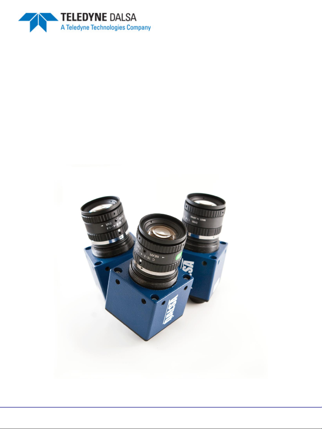
BOA Pro Vision System Components
BOA Pro vision systems are shipped with the components listed below. Take a few
moments to verify that everything has arrived in good condition. If your product has
been visibly damaged during shipment or is missing parts, please contact your Teledyne
DALSA representative immediately.
Standard components (ship with every BOA Vision System):
Component Description
BOA Pro Vision System
BVS-0640M-PRO or,
BVS-1024M-PRO or,
BVS-1280M-PRO
BVS-PRO-CD BOA Pro CD-ROM including the Sherlock Embedded Client
Mounting Screw Kit M4 screws for mounting the sensor (Qty 4)
BOA Pro Vision System. Fully integrated vision system with
640x480, 1024x768, or 1280x1024 monochrome sensor,
processing engine, Sherlock Embedded Server embedded
software, communications and light control.
software and associated product manuals and
documentation.
Optional components (sold separately):
Component Description
Cables
A-BVS-E8S-X
A-BVS-IO8S-X
A-BVS-L5S-X
BVS-PL-100 Panel Link breakout module. Provides Ethernet power and
BVS-PL-200 -E, -IO, -EIO Panel Link breakout modules with extended I/O capability.
M12-RJ45 Ethernet cordset (X; 5=5m, 10=10m)
M12 single-ended IO cordset (X ;5=5m, 10=10m)
M12 single-ended lamp cordset (X; 2=2m, 5=5m)
convenient panel access to BOA I/O
A-MB-BVS-0 Right Angle mounting block with 8 M4 screws
Lens Various Lens options available from DALSA
A-BVS-LCG-X Lens cover for BOA Vision System. Required for IP67
compliance. (x=35, 40 or 45 mm internal lens length)
A-BVS-LSS-F
A-BVS-M12-P
Lights Various Lighting options available from Teledyne DALSA
Set screws for Fujinon Lens
M12 plug for IP67 compliance
Version 02 teledynedalsa.com/ipd 7
Installation
Connecting the BOA Vision System
This section details how to connect the BOA vision system with its associated
components and factory environment.
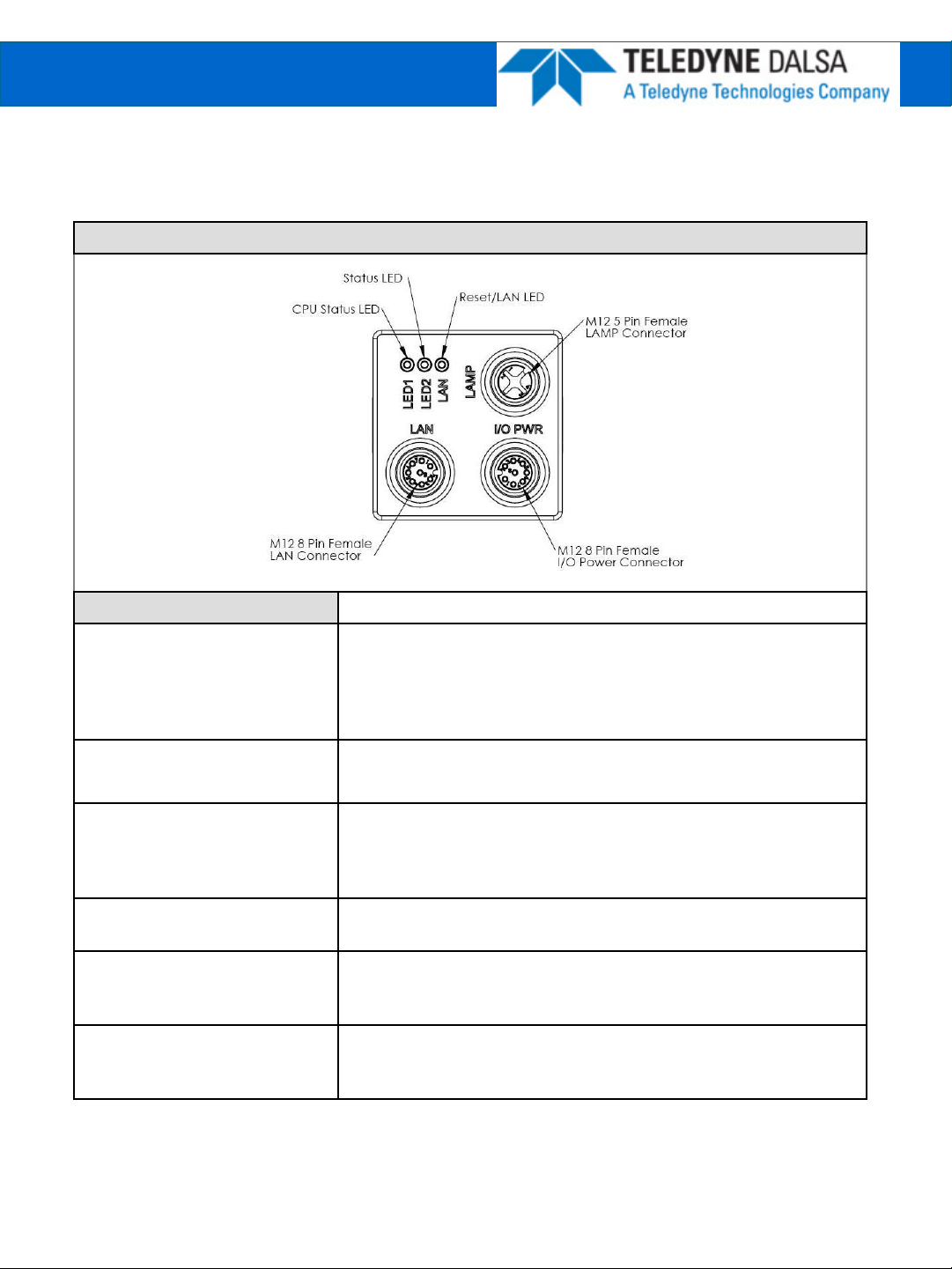
Camera Connectors and Indicators
Definitions Designator
LAN
I/O PWR
LAMP Provides PWR and strobe control to a local LED light source.
LAN LED Red/Green/Yellow = Network activity
LED2 Blue blink = Booting (stops after about 20 seconds)
LED1
10/100 BaseT Ethernet connection. Provides the primary
interface for configuring the camera, developing the application
and monitoring results.
NOTE: The camera can be powered from the Ethernet cable
directly (Passive Power over Ethernet)
Provides access to the camera I/O – 2 IN, 2 OUT Opto. Also
provides PWR input (12-30V).
NOTE: Lamp PWR is identical to BOA PWR input. The camera
should be powered from a 12V PWR source if the light requires
a 12V supply (Recommend 24V supply)
Blue = Warm Reset
Green Solid = Inspection Running
Red = Inspection Halted
Blue Solid = Camera booted, not configured
Green Solid = Inspection Running
Red Solid = Inspection Halted
Version 02 teledynedalsa.com/ipd 8
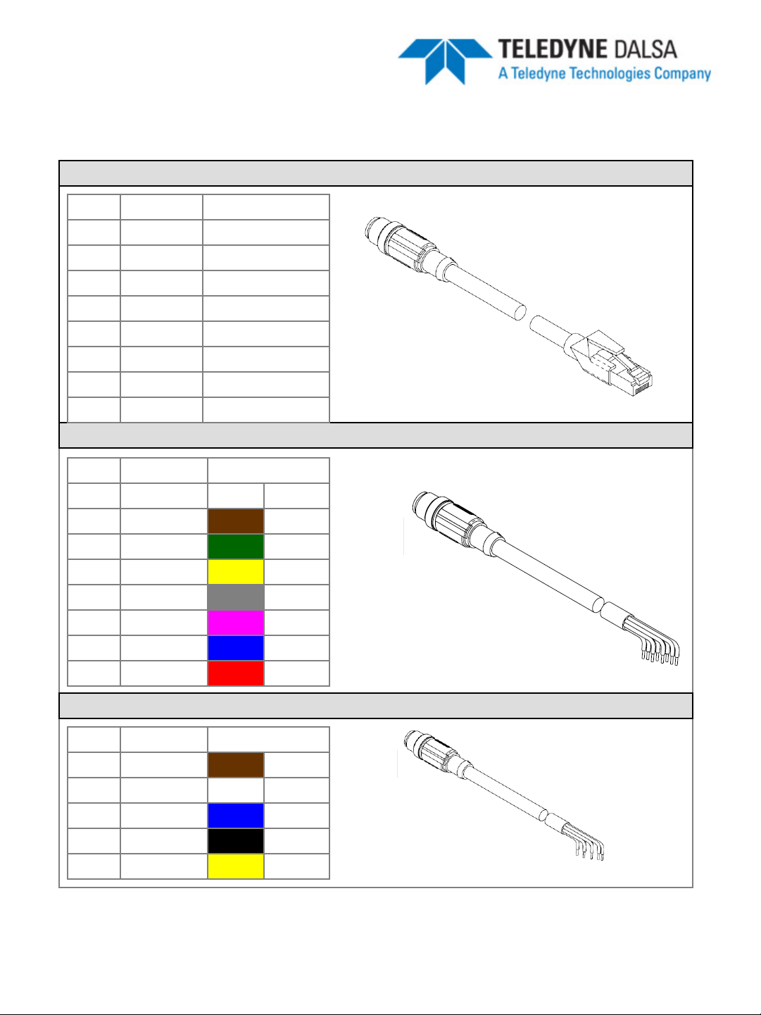
Cable Pinouts
The BOA vision system is compatible with M12 factory cordsets as show below:
LAN Connector Pinout and Cordset
Pin Name RJ45 Pin
1 PWR * 5
2 NC 7
3 GND * 8
4 TXD- 2
5 RXD+ 3
6 TXD+ 1
7 NC 4
8 RXD- 6
I/O-PWR Connector Pinout and Cordset
Pin Name Color
1 TRIG White
2 PWR Brown
3 IN0 Green
4 OUT1 Yellow
5 IN CMN Grey
6 OUT0 Pink
7 GND Blue
8 OUT CMN Red
LAMP Connector Pinout
Pin Name Color
1 PWR Brown
2 RS232 RX White
3 GND Blue
A-CAB-BVS-E8S-X
A-CAB-BVS-IO8S-X
4 STR Black
5 RS232 TX Yellow
A-CAB-BVS-L5S-X
* For Passive Power over Ethernet
Version 02 teledynedalsa.com/ipd 9
 Loading...