

Teledyne BlueView BV3200 Quick Start Manual
Quickstart Guide
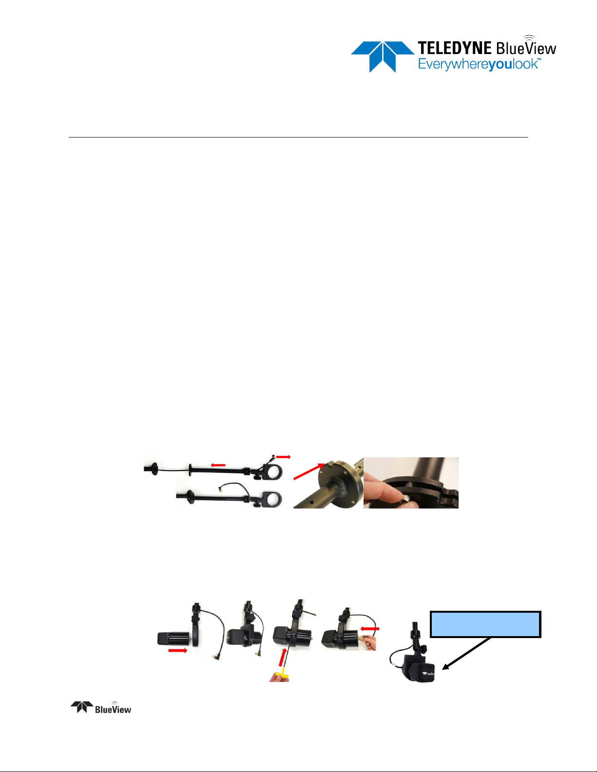
Logo facing up
Part Number: 204766-01 Rev A
Revision: October 2014
BV3200
For more detailed instructions, refer the complete manual on the BV3200 CD.
Install ProViewer Software
Insert the BV3200 CD in the CD-ROM drive and open the “ProViewer” folder.
Double-click the “setup” icon to begin installation.
Follow the instructions on the screen to complete the installation.
Configure your PC network interface card
Set your PC Network IP address to 192.168.1.3
Set the Net Mask to 255.255.255.0
Install the Junction Box
Connect the USB port on the control box to an available USB port on the PC. The “Found New
Hardware Wizard” will guide you through the installation process.
Choose “No, not this time” and click “Next.
Select “Install from a list or specific location” and click “Next.”
Select “Search for the best driver in these locations”, and check the box of “Search Removable
Media” and click “Next.”
Once the driver is installed, click “Finish.” If automatic driver installation fails, refer to the BV3200
manual for manual driver installation instructions.
Assemble the BV3200
Remove the pole unit from shipping case
Place the top and bottom pole pieces end to end and install screws
Connect the Sonar
Attach the sonar to the sonar clamp by loosening the four cap screws, sliding in the sonar and
retightening the four cap screws
Connect the sonar cable to the sonar connector
|+1.425.492.7376 | www.blueview.com
©2014 Teledyne BlueView, Inc. All rights reserved. All product names are trademarks of their respective companies
Page | 1

Tilt Angle Adjustment
Loosen the clamp angle adjustment knob by
turning the knob counterclockwise.
Lift the clamp until the angle adjustment selector
clears the angle keyway.
Select desired angle and tighten the angle
adjustment knob by turning clockwise until it is
snug.
Apply AC power to Junction Box
Start the ProViewer Software
Once the Sonar is fully powered
up(approximately 45 seconds) click the
connect button
In the settings tab under “COM Port
Settings” select the appropriate GPS COM
Port, Baud: 4800, Data Bits: 8, Parity:
None, Stop Bits: 1, Flow Control: None
Under “NMEA Sequences” select HDT,
RMC, ZDA
GPS Offset should be x: 0, y: 0
Click “Add Current”
Click “Start All”
Connect to Sonar & GPS
Connect the sonar as shown below, making sure the sonar cable is connected to the port labeled SONAR
and the standard Ethernet cable to the port labeled PC on the POE Box.
GPS heading, LAT, LONG should appear in lower left corner of ProViewer screen.
GPS Compass Calibration – Only perform these steps if the GPS data is incorrect.
Install BV3200 in final test location with the arrow on the top of the unit pointing parallel to the
boat centerline, in the direction of forward travel.
In calm seas, navigate to an open area away from boats, ferrous objects or obstructions.
Power-cycle the BV3200 junction box, open ProViewer software and display GPS data.
Within 2 minutes of cycling the power, steer in a circle at 4 to 6 kts, taking about 2 minutes to
complete a circle. Heading information will disappear, indicating calibration has begun.
Complete 3 to 4 circles, maintaining speed until heading information reappears, indicating
calibration is complete.
Shutdown
To avoid data loss, be sure to close and save any sonar data files before removing the sonar power.
When power cycling the sonar, be sure to allow at least 10 seconds of ‘off time’ before turning the sonar
back on.
|+1.425.492.7376 | www.blueview.com
©2014 Teledyne BlueView, Inc. All rights reserved. All product names are trademarks of their respective companies
Page | 2
 Loading...