

Page 1
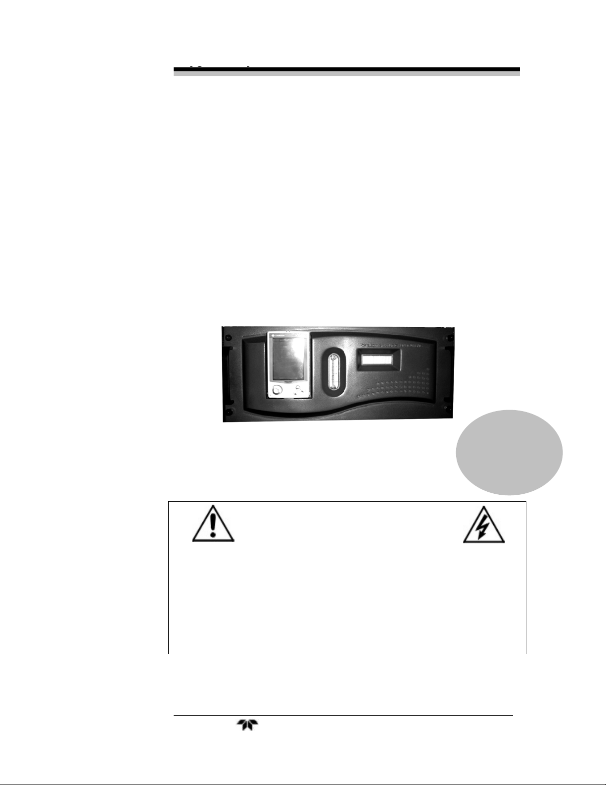
Oxygen Analyzer
OPERATING INSTRUCTIONS FOR
MM
OO
MM
OO
DD
DD
EEEELLLL BB
Oxygen Analyzer
BB
DD
DD
SSSS----33339999666600
00
P/N M71903
9/04/02
ECO # 02-232
DANGER
Tox ic g a se s a nd o r fla mma ble liq uids ma y be pr es e nt in this mon itor ing s y stem.
Personal protective equipment may be required when servicing this instrument.
Hazardous voltages exist on certain components internally which may persist
for a time even after the power is turned off and disconnected.
Only authorized personnel should conduct maintenance and/or servicing.
Before conducting any maintenance or servicing, consult with authorized
supervisor/manager.
Teledyne Analytical Instruments i
Page 2

BDS 3960
Copyright © 2002 Teledyne Analytical Instruments
All Rights Reserved. No part of this manual may be reproduced, transmitted, transcribed,
stored in a retrieval system, or translated into any other language or computer language in
whole or in part, in any form or by any means, whether it be electronic, mechanical,
magnetic, optical, manual, or otherwise, without the prior written consent of Teledyne
Analytical Instruments, 16830 Chestnut Street, City of Industry, CA 91749-1580.
Warranty
This equipment is sold subject to the mutual agreement that it is warranted by us free from
defects of material and of construction, and that our liability shall be limited to replacing or
repairing at our factory (without charge, except for transportation), or at customer plant at
our option, any material or construction in which defects become apparent within one year
from the date of shipment, except in cases where quotations or acknowledgements provide
for a shorter period. Components manufactured by others bear the warranty of their
manufacturer. This warranty does not cover defects caused by wear, accident, misuse,
neglect or repairs other than those performed by Teledyne or an authorized service center.
We assume no liability for direct or indirect damages of any kind and the purchaser by the
acceptance of the equipment will assume all liability for any damage which may result from
its use or misuse.
We reserve the right to employ any suitable material in the manufacture of our apparatus,
and to make any alterations in the dimensions, shape or weight of any parts, in so far as
such alterations do not adversely affect our warranty.
Important Notice
T hi s in str ument p ro v id es measur ement read in g s to it s user, an d serv es as a to o l b y w h i c h
v al uabl e d at a can b e g at h er ed . The i n fo rmat i on p r ov id ed by t h e in st r umen t may assi st th e user
i n el imi nati n g po ten ti al hazard s cau sed b y his p r ocess; ho wev er , it is essent ial t hat all
p er so nn el in v ol ved in th e u se o f t he in st ru men t or it s int er f ace, wi th t h e pr ocess b ein g
measu red , be pr op er l y tr ain ed i n t he pr ocess i tself , as well as all in s t r u m e n t a t io n rel at ed to i t .
The safety of personnel is ultimately the responsibility of those who control process
conditions. While this instrument may be able to provide early warning of imminent
danger, it has no control over process conditions, and it can be misused. In particular, any
alarm or control systems installed must be tested and understood, both as to how they
operate and as to how they can be defeated. Any safeguards required such as locks, labels,
or redundancy, must be provided by the user or specifically requested of Teledyne at the
time the order is placed.
Therefore, the purchaser must be aware of the hazardous process conditions. The purchaser
is responsible for the training of personnel, for providing hazard warning methods and
instrumentation per the appropriate standards, and for ensuring that hazard warning devices
and instrumentation are maintained and operated properly.
Teledyne Analytical Instruments, the manufacturer of this instrument, cannot accept
responsibility for conditions beyond its knowledge and control. No statement expressed or
implied by this document or any information disseminated by the manufacturer or its
agents, is to be construed as a warranty of adequate safety control under the user’s process
conditions.
Teledyne Analytical Instruments ii
Page 3

Oxygen Analyzer
Specific Model Information
The instrument for which this manual was supplied may
incorporate one or more options not supplied in the standard instrument.
Commonly available options are listed below, with check boxes. Any
that are incorporated in the instrument for which this manual is supplied
are indicated by a check mark in the box.
Instrument Serial Number: _______________________
Options Included in the Instrument with the Above Serial Number:
• 220 VAC: Instrument configured 200-240 VAC, 50/60Hz
power
Teledyne Analytical Instruments iii
Page 4
BDS 3960
Safety Messages
Your safety and the safety of others is very important. We have
provided many important safety messages in this manual. Please read
these messages carefully.
A safety message alerts you to potential hazards that could hurt you
or others. Each safety message is associated with a safety alert symbol.
These symbols are found in the manual and inside the instrument. The
definition of these symbols is described below:
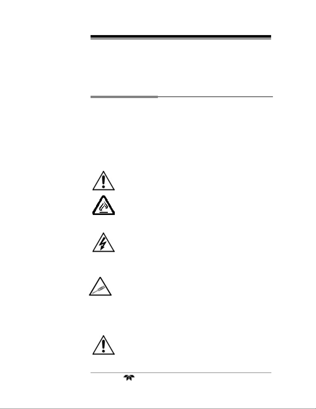
GENERAL WARNING/CAUTION: Refer to the
instructions for details on the specific danger. These cautions
warn of specific procedures which if not followed could cause
bodily Injury and/or damage the instrument.
CAUTION: HOT SURFACE WARNING: This warning is
specific to heated components within the instrument. Failure
to heed the warning could result in serious burns to skin and
underlying tissue.
WARNING: ELECTRICAL SHOCK HAZARD: Dangerous
voltages appear within this instrument. This warning is
specific to an electrical hazard existing at or nearby the
component or procedure under discussion. Failure to heed this
warning could result in injury and/or death from
electrocution.
Technician Symbol: All operations marked with this symbol
are to be performed by qualified maintenance personnel only.
No
Symbol
CAUTION: THE ANALYZER SHOULD ONLY BE USED FOR THE
NOTE: Additional information and comments regarding a
specific component or procedure are highlighted in the form
of a note.
PURPOSE AND IN THE MANNER DESCRIBED IN
THIS MANUAL.
Teledyne Analytical Instruments iv
Page 5

Oxygen Analyzer
IF YOU USE THE ANALYZER IN A MANNER OTHER
THAN THAT FOR WHICH IT WAS INTENDED,
UNPREDICTABLE BEHAVIOR COULD RESULT
POSSIBLY ACCOMPANIED WITH HAZARDOUS
CONSEQUENCES.
This manual provides information designed to guide you through
the installation, calibration and operation of your new analyzer. Please
read this manual and keep it available.
Occasionally, some instruments are customized for a particular
application or features and/or options added per customer requests.
Please check the front of this manual for any additional information in
the form of an Addendum which discusses specific information,
procedures, cautions and warnings that may be peculiar to your
instrument.
Manuals do get lost. Additional manuals can be obtained from
Teledyne at the address given in the Appendix. Some of our manuals are
available in electronic form via the internet. Please visit our website at:
www.teledyne-ai.com.
Teledyne Analytical Instruments v
Page 6

BDS 3960
Table of Contents
Safety Messages ..........................................................................iv
Table of Contents ......................................................................... vi
List of Figures............................................................................... ix
List of Tables ................................................................................ xi
Introduction .................................................................................13
1.1 Overview 13
1.2 Typical Applications 13
1.3 Main Features of the Analyzer 13
1.4 Front Panel (Operator Interface) 14
1.5 Rear Panel (Equipment Interface) 16
Operational Theory .....................................................................18
2.1 Introduction 18
2.2 BDS Sensor 18
2.2.1 Principles of Operation 18
2.2.2 Gas Flow Rate 21
2.2.3 Gas Pressure 22
2.2.4 Temperature effect 22
2.2.5 Recovery from High Level Oxygen Exposure 22
2.2.6 Background Gas Compatibility 23
2.2.7 Stability 24
2.2.8 Maintenance 24
2.3 Sample System 25
2.4 Electronics and Signal Processing 26
Installation ................................................................................... 30
3.1 Unpacking the Analyzer 30
Teledyne Analytical Instruments vi
Page 7

Oxygen Analyzer
3.2 Mounting the Analyzer 30
3.3 Rear Panel Connections 32
3.3.1 Gas Connections 32
3.3.2 Electrical Connections 33
3.3.2.1 Primary Input Power 34
3.3.2.2 50-Pin Equipment Interface Connector 34
3.4 Electrolyte Refill of BDS Sensor 39
3.5 Testing the System 40
3.6 Powering Up the System 41
Operation ..................................................................................... 42
4.1 Introduction 42
4.2 The Analyzer application 43
4.3 The System Screen 44
4.3.1 Communication Information and Calibration Parameters 44
4.3.2 Setting Software Parameters: Filter, Gas Factor,
Tmp. Coeff. 45
4.3.2.1 The Digital Filter 46
4.3.2.2 The Gas Factor 46
4.3.2.3 Temperature Coefficient 47
4.3.2.4 Set Defaults 48
4.4 Calibration of the Analyzer 49
4.4.1 Zero Cal 49
4.4.1.1 Zero Failure 50
4.4.2 Span Cal 50
4.4.2.1 Span Failure 51
4.5 The Alarms Function 51
4.6 The Range Function 53
4.6.1 Setting the Analog Output Ranges 53
4.6.2 Fixed Range Analysis 55
4.8 Signal Output 55
Teledyne Analytical Instruments vii
Page 8

BDS 3960
4.9 Switching The Program Back To The Front 56
Maintenance................................................................................. 58
5.1 Routine Maintenance 58
5.2 Adding Water to the BDS Sensor 58
5.3 Fuse Replacement 59
5.4 Battery Backup Replacement 60
5.5 Reinstalling Application software to PPC. 61
5.5 Major Internal Components 62
5.6 Cleaning 62
5.7 Troubleshooting 62
Appendix...................................................................................... 66
A-1 Specifications 66
A-2 Recommended 2-Year Spare Parts List 68
A-3 Drawing List 69
A-4 19-inch Relay Rack Panel Mount 69
A-5 Application notes 70
Material Safety Data Sheet 71
Index............................................................................................. 74
Teledyne Analytical Instruments viii
Page 9

Oxygen Analyzer
List of Figures
Figure 1-1: BDS-3960 Front Panel ................................................ 15
Figure 1-2: Model BDS 3960 Rear Panel ...................................... 17
Figure 2.1: Cross Section of the BDS Oxygen Sensor ................. 20
Figure 2.2: BDS sensor output at different gas flow rate ............... 21
Figure 2-3: A simplified BDS Sample System ............................... 22
Figure 2.4 Typical Purge-down Curve After Air Saturation............ 23
Figure 2.5: Adding DI Water to the BDS Sensor ..........................24
Figure 2-6: Flow Diagram.............................................................. 26
Figure 2-7: BDS 3960 Electronics Block Diagram ......................... 28
Figure 3-1: Model BDS 3960 Front Panel ..................................... 31
Figure 3-2: Required Assembly Drawer Clearance ....................... 31
Figure 3-3: Rear Panel of the Model BDS 3960 ........................... 32
Figure 3-4: Equipment Interface Connector Pin Arrangement....... 34
Figure 3-5: Adding Electrolyte to the BDS Sensor....................... 40
Figure 4-1: Main Menu .................................................................. 43
Figure 4.2: Parameter Selection Box............................................. 46
Figure 4.3: Range Options List Box............................................... 54
Figure 4.4: Range Setup Screen ................................................... 54
Figure 5.1 Adding Water into the BDS sensor............................... 59
Figure 5-2: Removing Fuse Block from Housing ........................... 60
Teledyne Analytical Instruments ix
Page 10

BDS 3960
Figure 5-3: Vacuum Degassing for the BDS Oxygen Sensor....... 64
Figure A-1: Single 19" Rack Mount (dimensions in mm) ............... 69
Teledyne Analytical Instruments x
Page 11

Oxygen Analyzer
List of Tables
Table 3-1: Analog Output Connections .........................................35
Table 3-2: Alarm Relay Contact Pins ............................................36
Table 3-3: Remote Calibration Connections.................................. 37
Table 3-4: Range ID Relay Connections ....................................... 39
Table 4-1: Gas Factor for Selected Gases .................................... 46
Table 4-2: Parameter Default Values ............................................ 48
Table 4-2: Linear Output for a 0-100 ppm O2 Range ................... 55
Table 4-3: Range ID Output .......................................................... 56
Teledyne Analytical Instruments xi
Page 12
BDS 3960
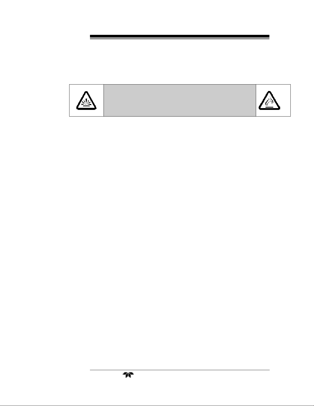
DANGER
COMBUSTIBLE GAS USAGE
WARNING
This is a general purpose instrument designed for usage in a
nonhazardous area. It is the customer's responsibility to
ensure safety especially when combustible gases are being
analyzed since the potential of gas leaks always exist.
The customer should ensure that the principles of operating
of this equipment is well understood by the user. Misuse of
this product in any manner, tampering with its components,
or unauthorized substitution of any component may
adversely affect the safety of this instrument.
Since the use of this instrument is beyond the control of
Teledyne, no responsibility by Teledyne, its affiliates, and
agents for damage or injury from misuse or neglect of this
equipment is implied or assumed.
Teledyne Analytical Instruments xii
Page 13

Oxygen Analyzer Introduction
Introduction
1.1 Overview
The Teledyne Analytical Instruments Model BDS 3960 Oxygen
Analyzer is a versatile instrument for detecting oxygen at the parts-perbillion (ppb) level in a variety of gases. This manual covers the Model
BDS 3960 General Purpose flush-panel and/or rack-mount units only.
These units are for indoor use in a non-hazardous environment.
1.2 Typical Applications
A few typical applications of the Model BDS 3960 are:
• Monitoring inert gas blanketing
• Air separation and liquefaction
• Chemical reaction monitoring
• Semiconductor manufacturing
• Petrochemical process control
• Quality assurance
• Gas analysis certification.
1.3 Main Features of the Analyzer
The Model BDS 3960 Oxygen Analyzer is sophisticated yet simple
to use. The main features of the analyzer include:
• Pocket PC with Windows CE operating system used as a
controller for analyzer functions.
• High resolution, accurate readings of oxygen content from
low ppb levels through 100 ppm. Large, bright, meter
readout.
• New BDS Sensing technology, patent pending.
• Versatile analysis over a wide range of applications.
• Microprocessor based electronics: 8-bit CMOS
microprocessor with 32 kB RAM and 8 kB ROM for I/O
operations.
Teledyne Analytical Instruments 13
Page 14

Introduction BDS 3960
• Three user definable output ranges (from 0-100 ppb through
0-100 ppm) allow best match to users process and
equipment, plus a fixed 100 ppm over range.
• Auto Ranging allows analyzer to automatically select the
proper preset range for a given measurement. Manual
override allows the user to lock on to a specific range of
interest.
• Two adjustable concentration alarms and a system failure
alarm.
• Two way RFI protection.
• Four analog outputs: two for measurement (0–1 VDC and
Isolated 4–20 mA DC) and two for range identification.
• Convenient and versatile, steel, flush-panel or rack-
mountable case with slide-out electronics drawer.
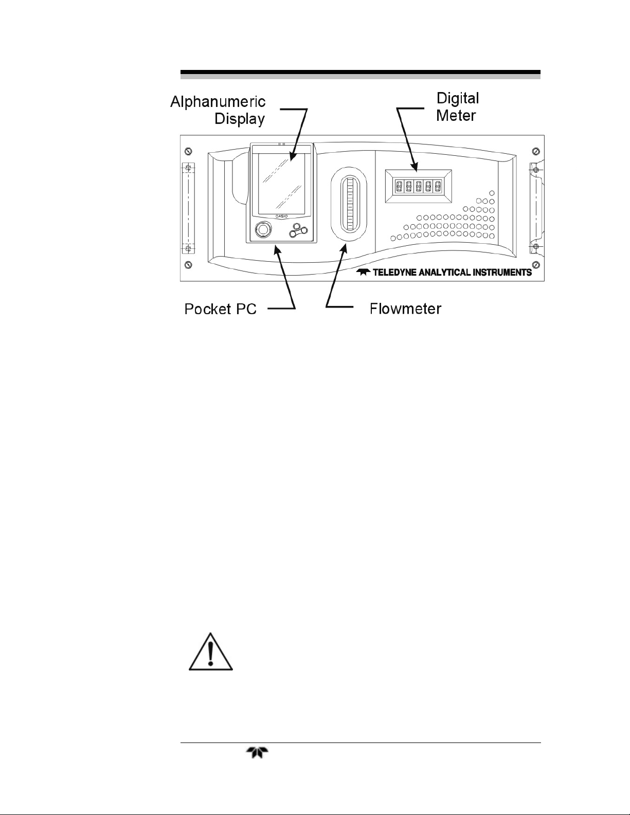
1.4 Front Panel (Operator Interface)
The standard BDS 3960 is housed in a rugged metal case with all
controls and displays accessible from the front panel. See Figure 1-1.
The front panel has the pocket PC, a digital meter, an alphanumeric
display, and a window for viewing the sample flowmeter.
There are no keys to press on the front panel. All interface with
the analyzer is done through the touchscreen of the pocket PC. The main
functions on the touchscreen are listed below.
• System Perform system-related tasks
(described in detail in chapter 4,
Operation.).
• Span Span calibrate the analyzer.
• Zero Zero calibrate the analyzer.
• Alarms Set the alarm setpoints and
attributes for Alarm 1 and Alarm 2.
• Range Set up the 3 user definable ranges
for the instrument.
• Quit Quit analyzer application.
Teledyne Analytical Instruments 14
Page 15
Oxygen Analyzer Introduction
Figure 1-1: BDS-3960 Front Panel
Digital Meter Display: The meter display is a Light Emitting Diode
(LED) device that produces large, bright, 7-segment numbers that are
legible in any lighting. It produces a continuous readout from 0-999.9
ppb and then switches to a continuous ppm readout from 0-100.00 ppm.
It is accurate across all analysis ranges without the discontinuity inherent
in analog range switching.
Flowmeter: Monitors the flow of gas past the sensor. Readout is 0.1 to
2.0 standard liters per minute (SLPM) of nitrogen
CAUTION: THE POWER CABLE MUST BE UNPLUGGED TO
FULLY DISCONNECT POWER FROM THE
INSTRUMENT. WHEN CHASSIS IS EXPOSED OR
WHEN ACCESS DOOR IS OPEN AND POWER
CABLE IS CONNECTED, USE EXTRA CARE TO
AVOID CONTACT WITH LIVE ELECTRICAL
CIRCUITS.
Teledyne Analytical Instruments 15
Page 16

Introduction BDS 3960
Access Drawer: For access t o the BDS S ensor And pr essur e regul ator.
T he f ront panel sli des out when the four thumb screws ar e loosened.
Openi ng the int er ior gives access to most ci rcui t boards t oo.
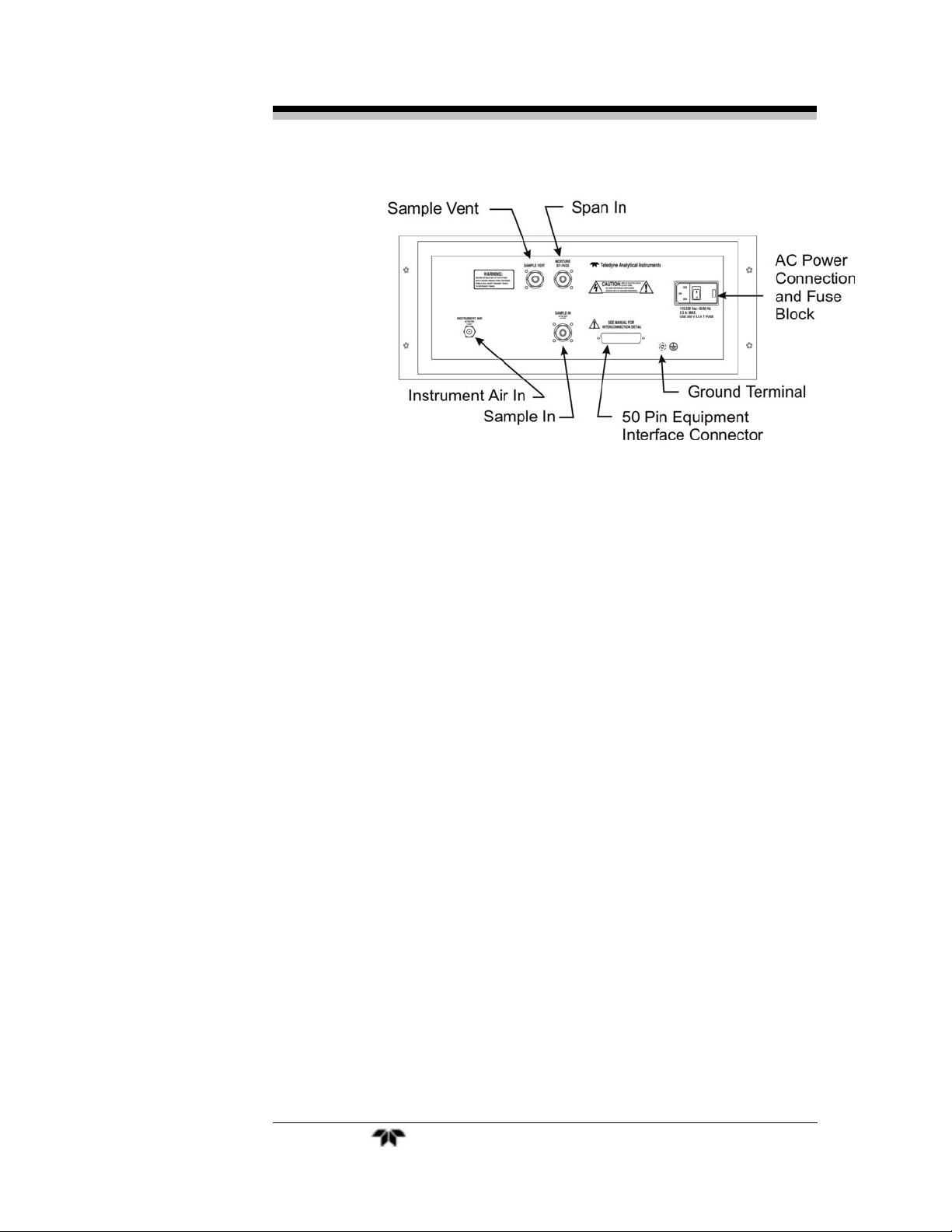
1.5 Rear Panel (Equipment Interface)
The rear panel, shown in Figure 1-2, contains the gas and electrical
connectors for external inlets and outlets. The connectors are described
briefly here and in detail in Chapter 3 Installation. Except for gas, AC
power, and RS-232 communications I/O, all user connections for analog
output, alarms, calibration and remote probe contacts are available
through the 50 pin equipment interface connector. User connections
made at the rear panel include:
• Power Connection 110 VAC power source (220 VAC
optional.
• Gas Inlet and Outlet One inlet and one exhaust out.
• Moisture By-pass Additional vent line for condensate
• Analog Outputs 0–1 VDC oxygen concentr ation plus
0-1 VDC r ange I D, and isolated
4–20 mA DC oxygen concentr ation
plus 4-20 mA DC range ID.
• Alarm Connections 2 concentration alarms and 1
system alarm.
• Remote Probe Used in the BDS 3960 for
controlling external solenoid
valves only.
• Remote Span/Zero Digital inputs allow external
control of analyzer calibration.
• Calibration Contact To notify external equipment that
instrument is being calibrated and
readings are not monitoring
sample.•
Range ID Contacts Four separate, dedicated, range
relay contacts. Low, Medium,
High, Cal.
Teledyne Analytical Instruments 16
Page 17
Oxygen Analyzer Introduction
Figure 1-2: Model BDS 3960 Rear Panel
Teledyne Analytical Instruments 17
Page 18

Operational Theory BDS 3960
Operational Theory
2.1 Introduction
The analyzer is composed of four subsystems:
• BDS Sensor
• Sample System
• Pocket PC
• Electronic I/O Signal Processing and Display
The sample system is designed to accept the sample gas and
transport it through the analyzer without contaminating or altering the
sample prior to analysis. The BDS Sensor is an electrochemical device
that translates the amount of oxygen present in the sample into an
electrical current. The Pocket PC processes the sensor signal and sends
messages to the I/O electronics to correctly display oxygen value as well
as control other signals to the customer interface. The Electronic I/O
signal processing amplifies the sensor signal, digitizes the sensor reading
and sends them to the pocket PC for processing. Then it receives
commands from the pocket PC to manipulate signals for the customer
interface.
2.2 BDS Sensor
2.2.1 Principles of Operation
The BDS oxygen sensor technology developed at Teledyne
Analytical Instruments is a result of TAI’s heavy investment on R&D
and expertise established during the half-century’s manufacturing of
electrochemical oxygen sensor. It stands for Bipotentiostat Driven
Sensor. A BDS oxygen sensor accurately translates the oxygen level in
the sample gas into to an electrical current signal.
A potentiostat contains three electrodes: a working electrode, a
reference electrode and a counter electrode. A Bipotentiostat is a
combination of two potentiostats that share the reference electrode and
the counter electrode. The potential at the working electrode is precisely
Teledyne Analytical Instruments 18
Page 19

Oxygen Analyzer Operational Theory
controlled with respect to the reference electrode. The counter electrode
is used to carry the current that flow through the sensor. A potentiostat is
typically constructed with several operational amplifiers. The three
electrodes in an electrochemical cell and the operational amplifiers in
the potentiostat constitute a feedback-control loop. The potentiostat
technology has been well accepted in the field of electrochemistry, and
proven effective in eliminating polarization of the reference electrode
and automatic compensating electric resistance in the cell.
In a BDS oxygen sensor, the sensing electrode is a working
electrode that is under precise potential control as discussed above. A
stable sensing electrode potential is very critical for an oxygen sensor to
achieve high stability, low noise and large dynamic range. The reference
electrode in a BDS sensor is a Ag/Ag2O electrode which is well known
for its stable electrode potential and compatibility with the KOH
electrolyte in an oxygen sensor. The counter electrode is made of a
Platinum wire.
The sensing process involves electrochemical reactions inside the
sensor. At the sensing electrode, oxygen is reduced at the controlled
potential:
O
+ 2H2O + 4e
2
-
— > 4OH
-
There is no net electrochemical reaction at the reference electrode
since it is connected to the high impedance input of the operation
amplifier.
The electrochemical reaction at the counter electrode is:
4OH- — > O2 + 2H2 O + 4e
-
It is noteworthy that reaction (2) is reverse of the reaction (1). It is
indicative of a net change of zero inside a BDS sensor throughout the sensing
process. This feature produces a long-term stability for the BDS sensor.
There are two resources of oxygen being reduced at the sensing
electrode: from the sample gas and dissolved oxygen within the
electrolyte. The oxygen molecules in the sample gas diffuse to the
sensing electrode through a diffusion barrier (controlled diffusion) to
produce a current signal which is proportional to the oxygen level in the
sample gas. However, the dissolved oxygen in the electrolyte also
diffuses through the electrolyte. It is reduced at the sensing electrode and
produces a background current. This background current represents the
detection limit of an oxygen sensor.
(1)
( 2)
Teledyne Analytical Instruments 19
Page 20
Operational Theory BDS 3960
The main advantage of the BDS technology lies in the unique
second potentiostat. It is designed to remove dissolved oxygen and other
impurities in the electrolyte. It eliminates the internal background
current which previously limited the detection process.
The second potentiostat is located adjacent to the sensing electrode.
It uses a novel material, Reticulated Vitreous Carbon (RVC) and precise
control of the potential to remove the dissolved oxygen and impurities in
the electrolyte efficiently. As the result, the BDS sensor achieves an
outstanding feature of absolute zero output in the absence of oxygen.
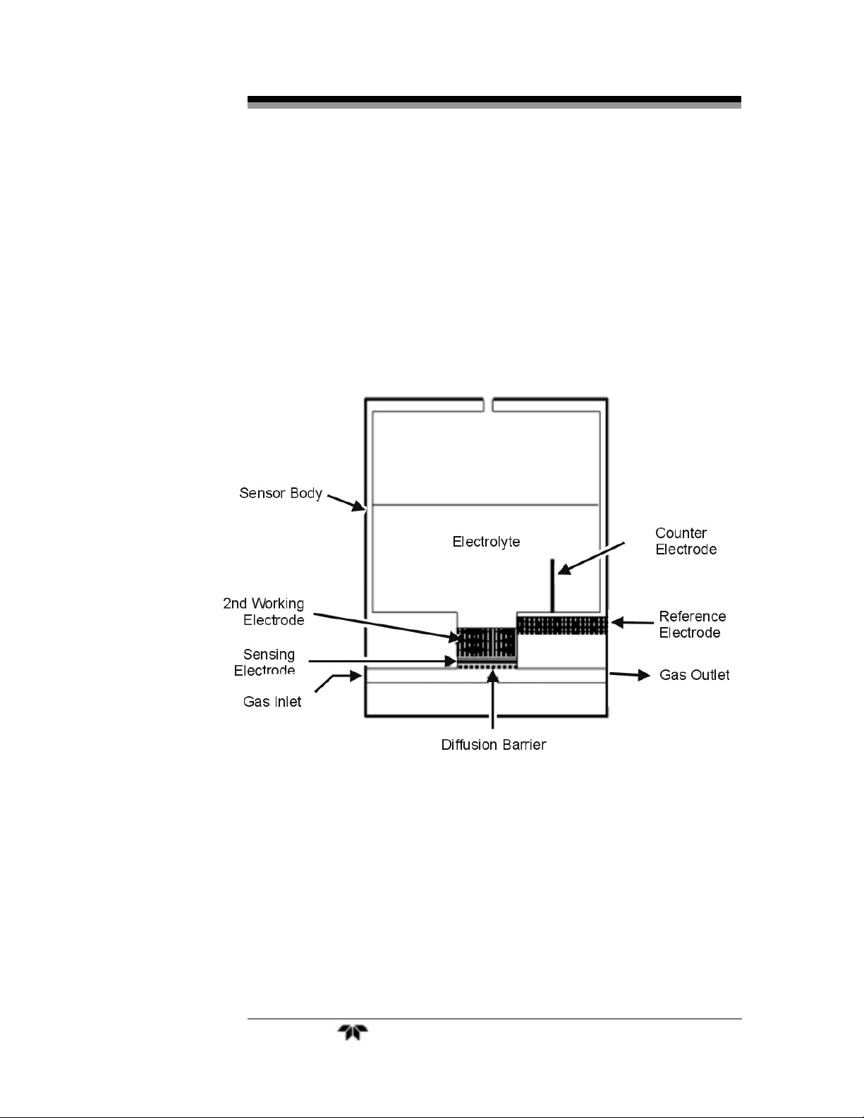
Figure 2.1: Cross Section of the BDS Oxygen Sensor
Figure 2.1 shows the schematic of a BDS oxygen sensor. The
sample gas enters the sensor through the gas inlet port and exits at the
gas outlet. A portion of oxygen in the sample gas diffuses through the
diffusion barrier to be reduced at the sensing electrode to form OH- in
the electrolyte. OH- can move freely through the porous 2nd working
electrode. At the counter electrode, OH- is oxidized back to oxygen.
Teledyne Analytical Instruments 20
Page 21
Oxygen Analyzer Operational Theory
While the 2nd working electrode allows OH- to move through, it
prevents the dissolved oxygen from the top portion of the sensor to reach
the sensing electrode. The reference electrode provides a potential
reference for both the sensing electrode and the 2nd working electrode.
NOTE: BDS technology and sensor is a patent pending
technology of Teledyne Analytical Instruments in the
United State of America as well as many foreign countries.
To learn more about BDS technology, please visit TAI’s web page at
http://www.Teledyne-AI.com
To learn more about potentiostat, visit Electochemical Society’s web
page at http://www.electrochem.org
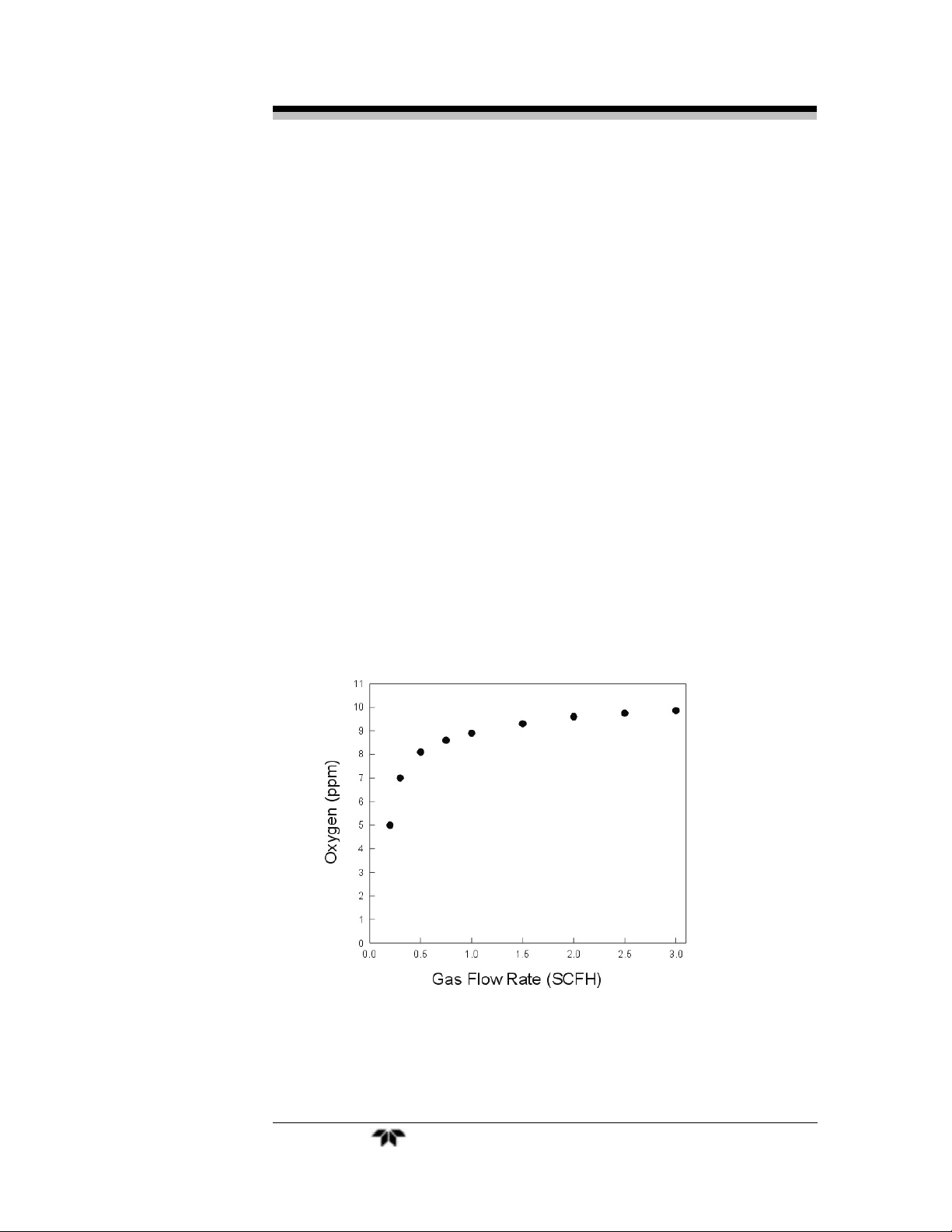
2.2.2 Gas Flow Rate
The output from a BDS oxygen sensor is relatively insensitive to
change of gas flow rate if operated in the range of 1 - 3 SCFH (in
nitrogen). The output drops when the flow rate is below 1 SCFH. Figure
2.2 is a typical curve showing the sensor outputs at different flow rate.
Figure 2.2: BDS sensor output at different gas flow rate
Teledyne Analytical Instruments 21
Page 22
Operational Theory BDS 3960
O
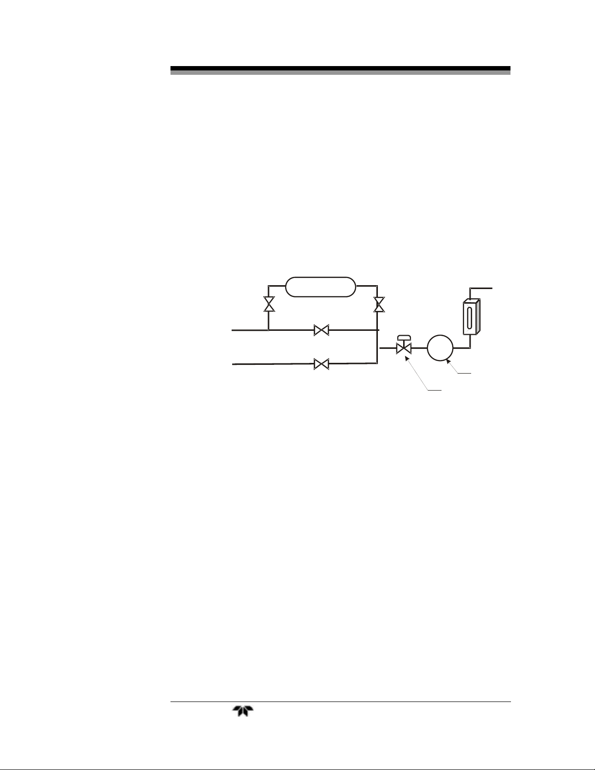
2.2.3 Gas Pressure
The analyzer is equipped with a pressure regulator as shown in
Figure 2-3. To access the pressure regulator, the front panel must be
opened. The inlet pressure should be regulated anywhere between 4 to
50 psig. The sensor is not affected by pressure changes in the inlet as
long as the analyzer vents to atmosphere. If the analyzer is not vented to
atmosphere, the downstream pressure must not exceed 10 inch of water.
A clogged or restricted vent or excessive pressure will force gas into the
electrolyte and cause damage to the BDS sensor.
xygen Scrubber
Vent
Sample
Inlet
Span
Inlet
Pressure Regulator
Flowmeter
BDS Sensor
Figure 2-3: A simplified BDS Sample System
2.2.4 Temperature effect
The raw output from a BDS oxygen sensor has a temperature
coefficient about 0.25% / °C. That is an average value, it changes as
temperature changes. This temperature effect is compensated by the
software throughout the operation temperature range (5 – 40°C).
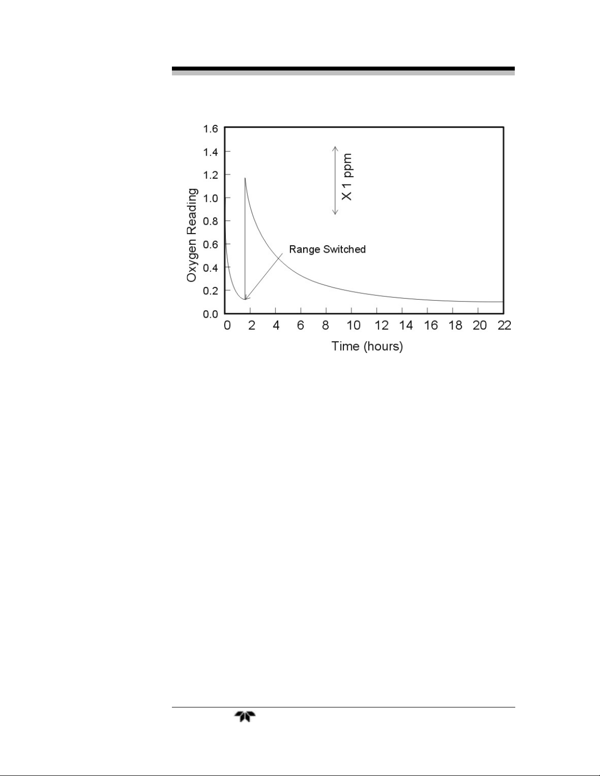
2.2.5 Recovery from High Level Oxygen Exposure
The ambient air contains about 210,000,000 ppb (2.1 x 10⁸)
oxygen. Figure 2.4 is a typical purge-down curve for a new BDS sensor
which had been air saturated. It is normal to take several hours, even
days for an air saturated BDS to purge down to a low ppb level.
Teledyne Analytical Instruments 22
Page 23
Oxygen Analyzer Operational Theory
Figure 2.4 Typical Purge-down Curve After Air Saturation
S h or t e n i ng t h e ai r exp o s u r e wi l l al l o w a f a s t e r se ns o r r ec o v e r y.
A ty p i c a l BD S se n s o r wi l l re c o v e r t o 1 pp m i n ap p r ox i m a t el y 25
m i nu t e s , t o 10 0 pp b af t e r 80 m i n , an d 10 pp b i n ab ou t 8 ho u r s , af t e r
s u f f e r i n g a t e n- m i n u t e ex p os u r e to ai r .
2.2.6 Background Gas Compatibility
T he BDS oxygen sensor wi l l work in i ner t gas backgr ounds,
i ncludi ng ni t rogen, hydr ogen, ar gon, heli um and ethane. The sensor
out put, however, i s dif fer ent in di ff erent backgr ound gases. For exam pl e,
t he sensor output i n a hydr ogen background is twi ce as much as it woul d
be in a ni tr ogen background. Therefor e, i t is recom mended to cali br ate t he
analyzer wit h an oxygen standar d that has a sim il ar background as the
sam pl e gas. If an oxygen st andar d is unavai l able for a par ti cul ar
background, a Gas F act or which is det er mi ned at TAI coul d be used t o
cor rect the sensor out put in dif f er ent backgr ound (see sect ion 4.3.9) .
Note: the gas flow meter in the analyzer is calibrated for air. The
error for measuring nitrogen is usually negligible. But for
Teledyne Analytical Instruments 23
Page 24

Operational Theory BDS 3960
hydrogen, it reads 100% lower. For example, when the
float ball in the flowmeter is at 0.5 SLPM, the actual flow
rate of hydrogen is about 1 SLPM.
The BDS oxygen sensor can tolerate exposure to acidic gases. Up
to 0.2% CO
has no effect to ppb level oxygen measurement.
2
2.2.7 Stability
The BDS sensor is essentially drift free. Typically a BDS sensor
requires no re-calibration over an entire year period. However, there
may be some intrusion to the zero during the maintenance. See next
section for details.
2.2.8 Maintenance
The only maintenance required on the BDS sensor is to replenish
distilled or de-ionized water every three to four months. It is not
necessary to take the analyzer out of service while adding water to the
sensor but caution should be taken to avoid spilling water on the PC
boards or other area inside the analyzer.
Figure 2.5: Adding DI Water to the BDS Sensor
Teledyne Analytical Instruments 24
Page 25

Oxygen Analyzer Operational Theory
There is a Max line and Min Line clearly marked on the BDS sensor
body. It is a good practice to check the electrolyte level every month and add
de-ionized water into the sensor whenever it is convenient.
When running dry gas through the sensor, the gas carries out moisture
from the sensor. Therefore, the electrolyte (10% KOH in water) inside the
sensor is gradually concentrated during the sensor operation. It typically takes
about four months for the electrolyte level to drop from the Max line to Min
line. When adding water to increase the electrolyte level from the Min line to
the Max line, it is typical that the oxygen reading will drift down about 10
ppb in an hour. If the oxygen content in the sample gas is very close to zero,
the analyzer may display a negative reading during this period. The sensor
will recover by itself during the following week. This drift-down then
recover-back phenomenon is caused by the quick dilution of the electrolyte
and re-establishment of a new equilibrium inside the sensor. To minimize
this effect, add a small amount of water each time and do this before the
electrolyte level reaches the Min line.
2.3 Sample System
The sample system delivers gases to the BDS sensor from the
analyzer rear panel inlet. Depending on the mode of operation either
sample or calibration gas is delivered.
The Model BDS 3960 sample system is designed and fabricated to
ensure that the oxygen concentration of the gas is not altered as it travels
through the sample system.
The sample system for the standard instrument incorporates 1/4" VCR
fittings for sample inlet, span inlet, and vent and Swagelock fittings for
instrument air tube connections at the rear panel. The sample or calibration
gas that flows through the system is monitored by a flowmeter downstream
from the sensor.
Figure 2-6 represents the flow diagram of the sampling system. In
the standard instrument, span gases can be connected to its own
separate inlet port. Solenoid valves are controlled by the software to
switch the proper gas when the analyzer enters the span mode. Zero gas
is generated internally when the sample gas is re-routed to go through an
oxygen scrubber before it is fed to the sensor. The life of the oxygen
sensor depends in two main factors: flow rate, oxygen impurity being
scrubbed. Thus, the life of the scrubber can vary depending on the
sample gas being used to zero the analyzer. It is recommended to change
the oxygen scrubber every two years. Use this as a guideline only.
Teledyne Analytical Instruments 25
Page 26

Operational Theory BDS 3960
Note that instrument air at a pressure of 70 to 80 psig is needed to
activate the proper valves.
Figure 2-6: Flow Diagram
2.4 Electronics and Signal Processing
T he Model BDS 3960 Oxygen Analyzer uses an 8051
m icrocontr ol l er wi th 32 kB of RAM and 8 kB of ROM to cont rol signal
processi ng,, i nput / output, and di splay functi ons f or the analyzer . Most of
t he processi ng power and deci si on making is done by t he soft war e
r unni ng on t he pocket PC (P PC). Syst em power is suppli ed fr om a
uni versal power supply module desi gned to be compat ibl e wi t h any
i nt er nat ional power sour ce.
The signal processing electronics including the microprocessor,
analog to digital, and digital to analog converters are located on the I/O
board at the bottom of the case. The preamplifier board is mounted on
top of the I/O board. These boards are accessible by sliding the front out.
Figure 2-7 shows a block diagram of the analyzer electronics.
In the presence of oxygen the sensor generates a current. A current
to voltage amplifier converts this current to a voltage which is further
amplified in the second stage amplifier.
The output from the second stage amplifier is sent to an 12 bit
analog to digital converter that is located in the same chip as the
microprocessor. The amplifier board also reads the ambient temperature
Teledyne Analytical Instruments 26
Page 27

Oxygen Analyzer Operational Theory
as the signal is passed to a second channel of the analog to digital
converter.
The raw counts of the analog to digital converter for both the
oxygen sensor amplifier and temperature amplifier are sent to the PPC
via RS232 interface once every second along with a status byte. The
PPC performs processing on this data to calculate oxygen concentration,
temperature, as well as decisions regarding the condition of the alarm
contacts, range, amplifier gain, solenoid control, and the analog output
required. After processing, the PPC sends a message back to I/O board,
via RS232, with commands for all the I/O functions. The 8051
microprocessor in the I/O board evaluates this data and the appropriate
control signals are directed to the LED display, alarms contacts, range
ID contacts, and digital to analog converter. The analog to digital
converter is a 12 bit device located in the microprocessor IC. The output
of the digital to analog converter with the help of some support
electronics produces the 4-20 mA DC and the 0-1 VDC analog
concentration signal outputs.
Signals from the power supply are also monitored, and through the
microprocessor, the system failure alarm is activated if a malfunction is
detected. Failure to communicate with the PPC will also trigger the
System alarm.
Teledyne Analytical Instruments 27
Page 28

Temperature
Sensor
BDS
Sensor
Operational Theory BDS 3960
Amplifiers
ADC
Alarm 1
Pocket
PC
Alarm 2
System
Alarm
Other
Outputs
UART
8051 processor
DAC
LED
Display
0-1 VDC and
4-20 ma
support
electronics
Figure 2-7: BDS 3960 Electronics Block Diagram
Teledyne Analytical Instruments 28
Page 29

Oxygen Analyzer Operational Theory
Teledyne Analytical Instruments 29
Page 30

Installation BDS 3960
Installation
Installation of the Model BDS 3960 Analyzer includes:
• Unpacking
• Mounting
• Gas connections
• Electrical connections
• Filling the Sensor with Electrolyte.
• Testing the system.
3.1 Unpacking the Analyzer
Although the analyzer is shipped complete, certain parts, such as
the electrolyte, are wrapped separately to be installed on site as part of
the installation. Carefully unpack the analyzer and inspect it for damage.
Immediately report any damage or shortages to the shipping agent.
3.2 Mounting the Analyzer
The Model BDS 3960 is for indoor use in a general purpose area. It
is NOT for hazardous environments of any type.
T he standard model is designed for f l ush panel m ounti ng. F igur e 3-1
i s an i l lust r at ion of the BDS 3960 st andard fr ont panel and mount ing
bezel . There ar e four mount ing hol es—one in each corner of t he ri gi d
f rame. The dr awings sect i on i n the r ear of thi s manual contai ns out l ine
dim ensi ons and mount ing hol e spaci ng di agram s.
Teledyne Analytical Instruments 30
Page 31

Oxygen Analyzer Installation
c
Figure 3-1: Model BDS 3960 Front Panel
Access to the electronics, the sensor, and sampling system is
accomplished by loosening the thumbscrews on the front of the
analyzer. The whole assembly will slide out toward the front. Allow
clearance for the assembly to slide out when maintenance is required.
Leave clearance of about 20 inches so that whole assembly can be pulled
out of its case. See Figure 3-2.
20 inch
clearan
Figure 3-2: Required Assembly Drawer Clearance
Teledyne Analytical Instruments 31
Page 32

Installation BDS 3960
3.3 Rear Panel Connections
Figure 3-3 shows the Model BDS 3960 rear panel. There are ports
for gas inlet and outlet, power, communication, and analog
concentration output.
Figure 3-3: Rear Panel of the Model BDS 3960
3.3.1 Gas Connections
T h e un i t is ma nu f a ct u r e d wi t h 1/ 4 in ch VC R f i t t i ngs wi t h t he
ex ce pt i on of i ns t r um e nt ai r fi t t i ng . Al l of th e gas conn ec t i o ns ar e
l o ca t e d on the r ea r of the ana l yz er . F or al l VC R f i t t i ngs , ins er t a gas ket
( T AI P N G2 84) bet wee n the f i t t i n gs an d ti ght en th e fe m al e and m al e
nu t s unt i l fi n ge r t i gh t ; th en by hol di n g th e m al e nut wi t h a wr e nc h,
t i gh t e n t he fe m a l e nu t wi t h a sec on d wr e nc h an add i t i o nal 1/ 6 tu r n .
SAMPLE IN: The gas of interest connections are made at the
and EXHAUST OUT connections. For zero calibration, the sample gas
IN
is rerouted through an oxygen scrubber to supply oxygen-free zero cal
gas. A VCR fitting is provided for the inlet connection.
The inlet gas pressure should be regulated to pressures between 5 to
50 psig so that the internal regulator can be adjusted to maintain a flow
between 0.5 to 1.0 SLPM. If pressure is too low, the flow will drop
below 0.5 SLPM which is below the threshold to which the sensor is
sensitive (see Section 2.2.2). If pressure is too high, it will force gas into
the electrolyte and cause damage to the sensor. The internal pressure
regulator is helpful if the sample pressure varies.
SAMPLE
Teledyne Analytical Instruments 32
Page 33

Oxygen Analyzer Installation
If greater sample flow is required for improved response time,
install a bypass in the sampling system upstream of the analyzer input.
SPAN IN: Span gas is connected to this port and it is automatically
routed by solenoid valves when the analyzer goes into the span mode. Its
pressure should be about the same as the inlet pressure of the sample
gas. This will ensure that flow remains unchanged when switching
between calibration and sample gases and this in turn increases accuracy
of the calibration.
EXHAUST OUT: Exhaust connections must be consistent with the
hazard level of the constituent gases. Check Local, State, and Federal
laws, and ensure that the exhaust stream vents to an appropriately
controlled area, if required.
CAUTION: CONNECT VENT LINES TO 1/4” OR LARGER
DIAMETER TUBING.
AIR INLET: The solenoid valves of the sampling system need air
pressure to actuate them. Use the compression fitting and 1/4” tubing to
connect instrument air (compressed air) with pressure in the range of 70
to 80 psig.
CAUTION: PRESSURE HIGHER THAN 100 PSIG CAN DAMAGE
THE SOLENOID VALVES.
3.3.2 Electrical Connections
For safe connections, no uninsulated wiring should be able to come
in contact with fingers, tools or clothing during normal operation.
CAUTION: USE SHIELDED CABLES. ALSO, USE PLUGS THAT
PROVIDE EXCELLENT EMI/RFI PROTECTION. THE
PLUG CASE MUST BE CONNECTED TO THE CABLE
SHIELD, AND IT MUST BE TIGHTLY FASTENED TO
THE ANALYZER WITH ITS FASTENING SCREWS.
ULTIMATELY, IT IS THE INSTALLER WHO ENSURES
THAT THE CONNECTIONS PROVIDE ADEQUATE
EMI/RFI SIELDING.
Teledyne Analytical Instruments 33
Page 34

Installation BDS 3960
3.3.2.1 PRIMARY INPUT POWER
The power cord receptacle and fuse block are located in the same
assembly. Insert the power cord into the power cord receptacle.
CAUTION: POWER IS APPLIED TO THE INSTRUMENT'S
CIRCUITRY AS LONG AS THE INSTRUMENT IS
CONNECTED TO THE POWER SOURCE.
The power supply requires 100–120 VAC, 50/60 Hz power source.
Fuse Installation: The fuse block, at the right of the power cord
receptacle, accepts US or European size fuses. A jumper replaces the
fuse in whichever fuse receptacle is not used. Fuses may not be installed
at the factory. Be sure to install the proper fuse as part of installation.
(See Fuse Replacement in Chapter 5, Maintenance.)
3.3.2.2 50-PIN EQUIPMENT INTERFACE CONNECTOR
Figure 3-4 shows the pin layout of the Equipment Interface
connector. The arrangement is shown as seen when the viewer faces the
rear panel of the analyzer. The pin numbers for each input/output
function are given where each function is described in the paragraphs
below.
Figure 3-4: Equipment Interface Connector Pin Arrangement
Analog Outputs: There are four DC output signal pins—two pins per
output. For polarity, see Table 3-1. The outputs are:
0–1 VDC % of Range: Voltage rises linearly with increasing
oxygen, from 0 V at 0 ppm to 1 V at
full scale ppm. (Full scale = 100% of
programmable range.)
0–1 VDC Range ID: 0.25 V = Low Range, 0.5 V = Medium
Range, 0.75 V = High Range, 1 V =
100ppm.
Teledyne Analytical Instruments 34
Page 35

Oxygen Analyzer Installation
4–20 mA DC % Range: Current increases linearly with
increasing oxygen, from 4 mA at 0
ppm to 20 mA at full scale ppm. (Full
scale = 100% of programmable range.)
4–20 mA dc Range ID: 8 mA = Low Range, 12 mA = Medium
Range, 16 mA = High Range, 20 mA
= 100ppm.
Table 3-1: Analog Output Connections
Pin Function
3+ Range ID, 4-20 mA, floating
4– Range ID, 4-20 mA, floating
5+ % Range, 4-20 mA, floating
6– % Range, 4-20 mA, floating
8+ Range ID, 0-1 V dc
23 – Range ID, 0-1 V dc, negative ground
24 + % Range, 0-1 V dc
7– % Range, 0-1 V dc, negative ground
Alarm Relays: The nine alarm-circuit connector pins connect to the
internal alarm relay contacts. Each set of three pins provides one set of
Form C relay contacts. Each relay has both normally open and normally
closed contact connections. The contact connections are shown in Table
3-2. They are capable of switching up to 3 amperes at 250 VAC into a
resistive load. The connectors are:
Threshold Alarm 1:
• Can be configured as high (actuates when concentration
is above threshold), or low (actuates when concentration
is below threshold).
• Can be configured as failsafe or nonfailsafe.
• Can be configured as latching or nonlatching.
• Can be configured out (defeated).
Teledyne Analytical Instruments 35
Page 36

Installation BDS 3960
Threshold Alarm 2:
• Can be configured as high (actuates when concentration
is above threshold), or low (actuates when concentration
is below threshold).
• Can be configured as failsafe or nonfailsafe.
• Can be configured as latching or nonlatching.
• Can be configured out (defeated).
System Alarm:
• Actuates when DC power supplied to circuits is
unacceptable in one or more parameters. Permanently
configured as failsafe and latching. Cannot be defeated.
Actuates if communication with PPC fails.
Further detail can be found in Chapter 4, Section 4-5.
Table 3-2: Alarm Relay Contact Pins
Pin Contact
45 Threshold Alarm 1, normally closed contact
28 Threshold Alarm 1, moving contact
46 Threshold Alarm 1, normally open contact
42 Threshold Alarm 2, normally closed contact
44 Threshold Alarm 2, moving contact
43 Threshold Alarm 2, normally open contact
36 System Alarm, normally closed contact
20 System Alarm, moving contact
37 System Alarm, normally open contact
Digital Remote Cal Inputs: Accept 0 V (off) or 24 V dc (on) inputs for
remote control of calibration. (See Remote Calibration Protocol below.)
See Table 3-3 for pin connections.
Teledyne Analytical Instruments 36
Page 37

Oxygen Analyzer Installation
Zero:
• Floating input—5 to 24 V input across the + and – pins
puts the analyzer into the Zero mode. Either side may be
grounded at the source of the signal. 0 to 1 volt across the
terminals allows Zero mode to terminate when done. A
synchronous signal must open and close the external zero
valve appropriately. See Remote Probe Connector. (The
–C option internal valves operate automatically).
Span:
• Floating input—5 to 24 V input across the + and – pins
puts the analyzer into the Span mode. Either side may be
grounded at the source of the signal. 0 to 1 volt across the
terminals allows Span mode to terminate when done. A
synchronous signal must open and close external span
valve appropriately. See Figure 3-5 Remote Probe
Connector. (The –C option internal valves operate
automatically.)
Cal Contact:
• This relay contact is closed while analyzer is spanning
and/or zeroing. (See Remote Calibration Protocol below.)
Table 3-3: Remote Calibration Connections
Pin Function
9+ Remote Zero
11 – Remote Zero
10 + Remote Span
12 – Remote Span
40 Cal Contact
41 Cal Contact
Remote Calibration Protocol: To properly time the Digital Remote Cal
Inputs to the Model BDS 3960 Analyzer, the customer's controller must
monitor the Cal Relay Contact.
Teledyne Analytical Instruments 37
Page 38

Installation BDS 3960
W h e n t h e c o n t a c t i s OP E N , t h e an a l y z e r i s an a l y z i n g , t h e
R e m o t e Ca l I n p u t s ar e be i n g po l l e d , an d a ze r o or sp a n co m m a n d
c a n be se n t .
When the contact is CLOSED, the analyzer is already calibrating. It
will ignore your request to calibrate, and it will not remember that
request.
Once a zero or span command is sent, and acknowledged (contact
closes), release it. If the command is continued until after the zero or
span is complete, the calibration will repeat and the Cal Relay Contact
(CRC) will close again.
For example:
1) Test the CRC. When the CRC is open, Send a zero command
until the CRC closes (The CRC will quickly close.)
2) When the CRC closes, remove the zero command.
3) When CRC opens again, send a span command until the
CRC closes. (The CRC will quickly close.)
4) When the CRC closes, remove the span command.
When CRC opens again, zero and span are done, and the sample is
being analyzed.
Note: The Remote Valve connections (described below) provides
signals to ensure that the zero and span gas valves will be
controlled synchronously.
Range ID Relays: There are four dedicated Range ID relay contacts.
The first three ranges are assigned to relays in ascending order—Low
range is assigned to Range 1 ID, Medium range is assigned to Range 2
ID, and High range is assigned to Range 3 ID. The fourth range is
reserved for the over Range (100 ppm). Table 3-4 lists the pin
connections. There is contact opening to indicate what range the
analyzer is on. The contacts open when the analyzer is on that range.
Teledyne Analytical Instruments 38
Page 39

Oxygen Analyzer Installation
Table 3-4: Range ID Relay Connections
Pin Function
21 Range 1 ID Contact
38 Range 1 ID Contact
22 Range 2 ID Contact
39 Range 2 ID Contact
19 Range 3 ID Contact
18 Range 3 ID Contact
34 Range 4 ID Contact (Over range)
35 Range 4 ID Contact (Over range)
3.4 Electrolyte Refill of BDS Sensor
The BDS sensor is shipped dry. It must be filled with the
electrolyte before operation. The electrolyte is a caustic solution (10%
KOH), supplied in five 50 ml bottles. Review the Material Safety Data
Sheet (MSDS) in Section A-6 before handling the electrolyte.
To refill the BDS sensor:
1. Loosen the thumb screws on the front and slide the drawer
halfway out.
2. Unscrew the sensor cap and disconnect sensor cable from the
BDS sensor.
3. Pour the electrolyte from the five small bottles into a larger
container.
4. Sparge the electrolyte with nitrogen gas at a flow of 100 CCM
for about 1/2 hour then pour into the provided wash bottle.
5. Ref. to Figure 3.5 for the method of adding electrolyte to the
sensor. It is important that as the sensor is being filled with the
electrolyte, filling is accomplished without trapping gas bubbles
in the lower part of the sensor.
6. Squirt electrolyte content into the sensor. Do it slowly until the
bottom parts of the sensor are fully immersed in the electrolyte.
Teledyne Analytical Instruments 39
Page 40

Installation BDS 3960
7. Pour the rest of the electrolyte into the sensor. Gas bubbles in the
top portion of the sensor do not affect the sensor performance.
One bottle of electrolyte is sufficient to rise the electrolyte level
to the MAX line. For the rest of sensor life, no further electrolyte
addition is needed.
8. Install the sensor cap.
9. Do not connect the sensor's electric connector at this stage.
Figure 3.5: Adding Electrolyte to the BDS Sensor
3.5 Testing the System
Before plugging the instrument into the power source:
• Check the integrity and accuracy of the gas connections.
Make sure there are no leaks. Gas connection should allow
for some movement on the drawer assembly so that the
pressure regulator and the sensor connector cable can be
reached inside.
• Check the integrity and accuracy of the electrical
connections. Make sure there are no exposed conductors
• Check pressure of sample gas as well as instrument air. Set
the internal pressure regulator fully counterclockwise.
Teledyne Analytical Instruments 40
Page 41

Oxygen Analyzer Installation
3.6 Powering Up the System
Before powering up the system, set the pressure regulator to
minimum to prevent damage due to incorrect setting. Power up the
system by turning on the switch on the rear. Then turn on the PPC by
pressing the button on its left side. Make sure that the Analyzer
application is running. If the Analyzer application is not running, launch
it by following the these steps:
• Tap on Start found on the taskbar either at the bottom or the
top of the LCD screen of the PPC to pull down a menu.
• Tap on Programs to bring up the programs browser.
• Then tap on the Analyzer icon found in the browser. This
should launch the Analyzer application.
• Adjust the internal pressure regulator until gas flow is in the
middle of the flowmeter, around the 1 SLPM mark.
• Purge the sensor for about 15 minutes, then proceed to
connect the sensor cable.
• Close the assembly drawer and tighten the thumb screws.
• Purge the analyzer until readings decrease below 50 ppb.
Teledyne Analytical Instruments 41
Page 42

Maintenance BDS 3960
Operation
4.1 Introduction
Once the analyzer has been installed, it can be configured for your
application. To do this you will:
• Set system parameters:
• Calibrate the instrument.
• Define the three user-selectable analysis ranges, then choose
autoranging or select a fixed range of analysis, as required.
• Set alarm setpoints, and modes of alarm operation (latching,
failsafe, etc).
Before you configure your BDS 3960, these default values are in
effect:
Ranges: LO = 100ppb , MED = 1000 ppb,
HI = 10 ppm, Over-Range = 100
ppm
Auto Ranging: ON
Alarm Relays: Defeated, Alarm 1 at 1000 ppb,
Alarm 2 at 100 ppb HI, Not
failsafe, Not latching.
Teledyne Analytical Instruments 42
Page 43

Oxygen Analyzer Maintenance
4.2 The Analyzer application
The Pocket Personal Computer (PPC) is the brains of the analyzer.
The PPC runs the Analyzer program installed by TAI. For the
instrument to operate, the program must be launched as instructed in
section 3.6.
When the program is launched the main screen will appear as
shown below.
Figure 4-1: Main Menu
The screen shows controls that should be familiar to anyone who has
used a personal computer.
• Alarm 1. Pressing this button opens a new screen where
Alarm 1 trigger point and options can be set.
• Alarm 2. Pressing this button opens a new screen where
Alarm 2 trigger point and options can be set.
• Zero. Pressing this button opens a screen for the zero
calibration function.
• Span. Pressing this button opens the screen for the span
calibration function.
Teledyne Analytical Instruments 43
Page 44

Maintenance BDS 3960
• System. Pressing this button will open a second screen that
consists of several variables that regulate the internal
operations of the analyzer.
• Training Video. This buttons launches a video player. At this
point you could view a short training video regarding BDS
technology. The presentation will time out and return back to
the Analyzer application after a period of time.
• Ranges. The list box is used to set the analyzer on a specific
range as well as set the limits of the ranges.
Any function can be selected at any time by pressing the
appropriate button. The order as presented in this manual is appropriate
for an initial setup.
Each of these functions is described in greater detail in the
following procedures.
4.3 The System Screen
Pressing the System button on the main screen will bring the
System screen.
The System screen will time out in five minutes and return to the
main screen. Pressing the Done button will also return you to the main
screen.
4.3.1 Communication Information and
Calibration Parameters
The first block on the System screen displays information about
data received, calibration parameters, and data sent to the I/O hardware.
Received data: 014508900
Zero Offset: 0
Span Factor: 38.00
Amp Gain/Range ID/DAC: 0/0/265
The first line displays the data received from the I/O PCB. It consists of
nine digits. The first four digits are the Analog to Digital counts of the BDS
sensor amplifier. The range of this count is between 0000 and 4095. The
following four digits are the Analog to Digital counts of the temperature
Teledyne Analytical Instruments 44
Page 45

Oxygen Analyzer Maintenance
amplifier. The range of this count is the same as the BDS sensor, 0000 to
4095. The last digit is a status digit—zero indicates the I/O PCB is in normal
mode. If the I/O PCB receives a remote command to zero or span, it will let
the PPC program know through this digit.
Zero Offset line displays the actual Analog to Digital count of the
electronics plus sensor offset stored in the memory of the PPC. The
lower the number the better, but a high number does not hinder the
performance of the sensor very much. One reason for a high count could
mean that the sensor is still drifting downward and therefore an
additional zero calibration might be needed to maintain accuracy.
Span Factor displays a number which is a factor needed to convert
digital counts to PPB oxygen concentration. This number should be
between 10 and 40.
AmpGain/RangeID/DAC displays the command sent to the I/O PCB
and determines what gain the amplifier should have and what range ID
contact should open. Both numbers are from 0 to 4. Usually, with default
ranges, they should be the same but not necessarily.
DAC is a count number sent to the analog to digital converter of the
I/O PCB. This sets the output for the concentration 0-1 vdc and 4-20 madc
outputs. Its range is from 0 to 4095. A large discrepancy between AmpGain
and RangeID would point to a hardware problem e.g.:
AmpGain/RangeID/DAC: 0/4/265.
4.3.2 Setting Software Parameters: Filter, Gas
Factor, Tmp. Coeff.
There are three parameters that are under the control of the user and
are accessible from the parameter selection box as shown below. These
are:
• Digital filter—noise reduction
• Gas Factor—compensates for different background gases
• Temperature coefficient—corrects baseline drift due to
temperature.
Teledyne Analytical Instruments 45
Page 46

Maintenance BDS 3960
Select Factor to Adjust
Filter Gas Factor
Tmp. Coeff.
Figure 4.2: Parameter Selection Box
4.3.2.1 THE DIGITAL FILTER
The Analyzer software performs a digital operation to reduce the
noise from the BDS sensor and amplifier. This filtering is reduced to
around 10 ppb. If the signal exceeds 10 ppb, the filter disengages in
order to track the transient faster. The number approximately
corresponds to the response time of the filter in minutes from 10 to 90
%. The range is from 1 to 60 minutes of the 90 % response time. Five
minutes is the default.
4.3.2.2 The Gas Factor
The gas factor coefficient in the BDS 3960 is the ratio of the output
of the sensor taken in a N2 background over the output of the sensor in
the new background gas. The output of the sensor depends on the
mechanics of diffusion. Since the diffusion coefficient of oxygen
depends on the viscosity of the background gas, according to the laws of
diffusion, the output of the sensor becomes inversely proportional to the
viscosity of the background gas.
The output of the sensor can be predicted by looking up the
viscosity of the new background gas and compare it to the viscosity of
N2 at the same temperature. Using values obtained from the a science
handbook, the following gas factor coefficients for the BDS sensors are
calculated
Table 4-1: Gas Factor for Selected Gases
N2 = 1*
H2= 1.99
He= 0.90
Ar= 0.79
Teledyne Analytical Instruments 46
Page 47

Oxygen Analyzer Maintenance
*Output normalized by calibrating with a span gas in N
.
2
The values in Table 4-1 are theoretical but should give a first
approximation as to what the output of the sensor will be in the new
background gas. The BDS 3960 will make further refinements once the
proper gas factor is input.
The working range of adjustment is 0.25 to 2.50. This factor will
divide the output. For example if the factor is set to 2.00, the output of
the sensor, when read by the PPC application will be divided by two.
Special consideration on the working range: Changing the gas
correction factor has an effect on the maximum working range of the
analyzer, e.g.: if a gas factor of 2.00 is selected the maximum working
range of the analyzer is 50 ppm. Any reading above this, may saturate
the amplifier.
4.3.2.3 TEMPERATURE COEFFICIENT
The output of the sensor is affected by temperature. There are two
types of temperature compensation on the BDS 3960. One is the
compensation to high levels of oxygen, more than 100 ppb. This effect is
transparent to the user and is handled by the software application on the
PPC. It requires no input from the user. The second compensation
involves the baseline drift due to temperature. This value is generally set
at the factory but can be modified or adjusted by the user. Since the
sensor is temperature controlled, the default is zero. The following
discussion is just information on its possibilities.
The baseline drift temperature coefficient is a number with units of
ppb/degree centigrade and must be matched to the sensor’s characteristic
drift over temperature. This coefficient ranges from 0.50 to 1.75 ppb/°C.
Note: The coefficient is different from sensor to sensor. If the
sensor is replaced, a new coefficient must be entered. TAI
can supply this coefficient or it may be determined by the
user.
The coefficient can be adjusted between 0.00 and 5.00 using the Up
and Down buttons on the instrument. To estimate it in the field:
1. Set the coefficient to zero.
2. Run the analyzer on “Zero” calibration gas for two weeks or
until a baseline stability is reached, i.e. the oxygen reading does
not fluctuate.
Teledyne Analytical Instruments 47
Page 48

Maintenance BDS 3960
3. After the sensor has been purged for at least two weeks and the
baseline is stable, monitor the oxygen reading and ambient
temperature over a minimum period of 24 hours.
Take the maximum and minimum oxygen readings, and the
maximum and minimum temperature readings.
4. Calculate the coefficient using the relation:
Coefficient = (O
2 max
- O2
) ÷ (Temp
min
- Temp
max
min
)
For example:
In a 24 hour run:
= 3.55 ppb
O
2 max
O2
= 1.75 ppb
min
Temp
Temp
= 24.5 degrees C.
max
= 22.1 degrees C.
min
Coefficient = (3.55-1.75)ppb ÷ (24.5-22.1) °C = 0.75 ppb/°C.
This value is currently set to zero, since the sensor is
temperature controlled and should be left at zero unless qualified
personnel give instructions to change it.
4.3.2.4 SET DEFAULTS
The Set Defaults button will reset all parameters in the software,
such as calibration, alarm and range settings, Filter, Gas Factor,
temperature coefficient, etc. to their factory default values. Some of the
default values are listed below:
Table 4-2: Parameter Default Values
Parameter Default Value
Zero Offset 0
Span Gas 8.00 PPM
SpanFactor 24.42 (Default span factor =
100000 ppb/ 4095 ADC counts)
Teledyne Analytical Instruments 48
Page 49

Oxygen Analyzer Maintenance
Filter 5 minutes
Gas Factor 1.00
Temperature Coef. 0 ppb/degree centigrade
Alarm 1 setpoint 1000 ppb
Alarm 2 setpoint 100 ppb
Pressing the Set Defaults button brings up a confirmation dialog
box. Press Yes to reset to the defaults or No to keep the current values.
4.4 Calibration of the Analyzer
The analyzer must be calibrated prior to use. For most applications
where the desired range of measurement is 0 to 10 ppm, or less we
recommend the analyzer be calibrated using a span gas with a
concentration between 7.0 to 9.0 ppm oxygen in nitrogen. This will
require that calibration be performed in the 0-10 ppm analyzer range.
Before the cell is ready for calibration, it must be purged with
sample gas to a low oxygen level—preferably below 0.1 ppm. If the
oxygen content of the sample gas is higher than 0.1 ppm, a zero gas such
as nitrogen having an oxygen concentration below 0.1 ppm may be
required.
4.4.1 Zero Cal
The BDS Sensor has a zero offset of less than 5 ppb oxygen.
Normally, the offset slowly decreases during the first 7 to 10 days of
operation, and is expected to reach a steady value after this time.
Generally, the value of the zero offset is part of the oxygen reading
of the sample gas as shown by the analyzer readout. As an example, a
reading of 5 ppb oxygen may include 0.4 ppm oxygen in the sample gas
and a 5 ppb zero offset.
The determination of the zero offset requires the use of oxygen free
gas to the analyzer. The BDS 3960 has an oxygen scrubber as an
integral part of its sample system. The software and electronics
automatically re-route the sample gas through the scrubber to provide
the sensor with oxygen free gas. Best results as well as prolonged
scrubber life is attained when the oxygen concentration of the sample
gas is below 1 ppm oxygen.
Teledyne Analytical Instruments 49
Page 50

Maintenance BDS 3960
A zero calibration is not recommended during the first 10 days of
the operation of the cell.
The ZERO button on the Main screen is used to enter the zero
calibration function. Zero calibration can be performed either
automatically or manually.
In the automatic mode, an internal timer will purge sensor for five
minutes before registering the zero offset of the sensor plus electronics.
As the timer counts down, you can force the analyzer to accept the
current zero offset using the Accept button. Pressing the Accept button
anytime during the countdown period forces the analyzer to accept the
zero offset calibration.
Pressing Cancel will return the analyzer back to the analyze mode
without accepting the zero calibration. In this case, the previous zero
calibration values will remain as the current values.
4.4.1.1 ZERO FAILURE
The analyzer checks the output of the cell at the end of the span. If
the raw output of the cell produces an Analog to Digital converter count
less than 4000 on amplifier gain 0, the zero will not be accepted. The
analyzer will use the previous calibration values, and display at the top
of the main screen:
ZERO-CALIBRATION
ERROR
4.4.2 Span Cal
The SPAN button on the main screen is used to span calibrate the
analyzer. Span calibration can be performed automatically or manually.
In the automatic mode, an internal timer will purge sensor for five
minutes before taking in the zero offset of the sensor plus electronics.
Again, the ACCEPT button can be pressed at anytime during the
countdown period to accept the zero offset calibration.
Pressing the CANCEL button will return the analyzer to the
analyze mode without accepting the zero calibration. The previous zero
calibration will still be in effect.
Teledyne Analytical Instruments 50
Page 51

Oxygen Analyzer Maintenance
4.4.2.1 SPAN FAILURE
The analyzer checks the output of the cell at the end of the span. If
the raw output of the cell is less than 1.5 nA/ppb or more than 13.5
nA/ppb O
, the span will not be accepted. The analyzer will return to
2
the previous calibration values, and display at the top of the main
screen:
SPAN-CALIBRATION
ERROR
4.5 The Alarms Function
The Model BDS 3960 is equipped with 2 fully adjustable
concentration alarms and a system failure alarm. Each alarm has a relay
with a set of form “C" contacts rated for 3 amperes resistive load at 250
VAC. See Figure 3-5 in Chapter 3, Installation and/or the
Interconnection Diagram included at the back of this manual for relay
terminal connections.
The system failure alarm has a fixed configuration as described in
Chapter 3 Installation.
The concentration alarms can be configured from the PPC software
as either high or low alarms by the operator. The alarm modes can be set
as latching or non-latching, and either failsafe or non-failsafe, or, they
can be defeated altogether. The setpoints for the alarms are also
established using this function.
Depending on your process, you can choose to configure the alarms
in a number of ways. Consider the following four points:
1. Which if any of the alarms are to be high alarms and which if
any are to be low alarms?
Setting an alarm as HIGH triggers the alarm when the oxygen
concentration rises above the setpoint. Setting an alarm as LOW
triggers the alarm when the oxygen concentration falls below
the setpoint.
Decide whether you want the alarms to be set as:
• Both high (high and high-high) alarms, or
• One high and one low alarm, or
• Both low (low and low-low) alarms.
Teledyne Analytical Instruments 51
Page 52

Maintenance BDS 3960
2. Are either or both of the alarms to be configured as failsafe?
In failsafe mode, the alarm relay de-energizes in an alarm
condition. For non-failsafe operation, the relay is energized in
an alarm condition. You can set either or both of the
concentration alarms to operate in failsafe or non-failsafe mode.
3. Are either of the alarms to be latching?
In latching mode, once the alarm or alarms trigger, they will
remain in the alarm mode even if process conditions revert back
to non-alarm conditions. This mode requires an alarm to be
recognized before it can be reset. In the non-latching mode, the
alarm status will terminate when process conditions revert to
non-alarm conditions.
4. Are either of the alarms to be defeated?
The defeat alarm mode is incorporated into the alarm circuit so
that maintenance can be performed under conditions which
would normally activate the alarms.
The defeat function can also be used to reset a latched alarm.
(See procedures, below.)
Each of the concentration alarms have their own button on Main
display of the PPC application, ALARM 1 and ALARM 2. Once you
press on the alarm buttons you will be presented with alarm setup
screen.
Five parameters can be changed on the alarm setup screen:
1. Value of the alarm level—#### ppb (oxygen); value can be set
from 0 to 100,000 ppb.
2. Out-of-range direction—High or Low
3. Latch control—Latching or Non-latching.
4. On/off Control—Active or Defeated.
5. Safety Mode—Failsafe or Non-failsafe.
To reset a latched alarm, go to On/off Control and select defeated.
Teledyne Analytical Instruments 52
Page 53

Oxygen Analyzer Maintenance
4.6 The Range Function
The Range function allows the operator to program up to four
concentration ranges to correlate with the DC analog outputs. If no
ranges are defined by the user, the instrument defaults to:
Range 1 = 0–100 ppb
Range 2 = 0–1000 ppb
Range 3 = 0–10000 ppb
Range 4 = 0–100000 ppb
The Model BDS 3960 is set at the factor y to default to autoranging. I n
thi s mode, the PPC applicat ion automati cally responds to concentration
changes by swit ching ranges for optimum readout sensitivi ty. If the current
range lim its ar e exceeded, the instrument wil l automatically shift to the next
higher range. I f the concentration fall s to below 90% of full scale of the
next lower range, the instr ument will switch to that range. A corresponding
shi ft in the DC percent-of- range output , and in the range ID outputs, will be
not iced.
The autoranging feature can be overridden so that analog output
stays on a fixed range regardless of the oxygen concentration detected. If
the concentration exceeds the upper limit of the range, the DC output
will saturate at 1 VDC (20 mA at the current output).
Even if the output is set to a fixed range, the digital readout of the
concentration is unaffected by the fixed range. It continues to read
accurately with full precision. See Front Panel description in Chapter 1.
The automatic fourth range is always 0-100000 ppb (100 ppm) and
should not be adjusted.
4.6.1 Setting the Analog Output Ranges
To set the ranges, click on the list box on the main screen. The
following options will pop down.
Teledyne Analytical Instruments 53
Page 54

Maintenance BDS 3960
Figure 4.3: Range Options List Box
To Set the ranges to values different than the default, click on ‘Set
Range’ and the Set Range screen will pop up.
Set Range 1 Limit
Upper Limit PPB
UP
OK
CANCEL
DNRANGE
Figure 4.4: Range Setup Screen
The first screen allows you to set range 1. If you click on the Range
button, it will take you to the setup of range 2. Click Range again will
take you to the setup of range 3, then range 4, then back again to range
1. Note that ranges and alarms are set in ppb units.
Note: The ranges must sequentially increase from low to high, for
example, if range 1 is set as 0–100 ppb and range 2 is set
Teledyne Analytical Instruments 54
Page 55

Oxygen Analyzer Maintenance
as 0–1000 ppb, range 3 cannot be set as 0– 500 ppb since
it is lower than range 2.
Note: Refer to Section 4.3.2.2 to find maximum working range.
4.6.2 Fixed Range Analysis
The autoranging mode of the instrument can be overridden, forcing
the analyzer DC outputs to stay in a single predetermined range.
To switch from autoranging to fixed range analysis, click on the list
box of the main screen, as shown on figure 4.3, then select on the range
of interest.
4.8 Signal Output
The standard Model BDS 3960 Oxygen Analyzer is equipped with
two 0–1 VDC analog output terminals (one concentration and one range
ID), and two isolated 4–20 mA DC current outputs (one concentration
and one range ID) accessible from the 50-pin equipment interface
connector located on the back panel.
See Rear Panel in Chapter 3, Installation, for illustration and pin
configuration of the interface connector.
The signal output for concentration is linear over the currently
selected analysis range. For example, if the analyzer is set on a range
that was defined as 0–100 ppb O2, then the output would be as shown in
Table 4-2.
Table 4-2: Linear Output for a 0-100 ppm O2 Range
Voltage Signal Current Signal
ppb O
2
0 0.0 4.0
10 0.1 5.6
20 0.2 7.2
30 0.3 8.8
40 0.4 10.4
50 0.5 12.0
Output (VDC) Output (mA DC)
Teledyne Analytical Instruments 55
Page 56

Maintenance BDS 3960
60 0.6 13.6
70 0.7 15.2
80 0.8 16.8
90 0.9 18.4
100 1.0 20.0
The analog output signal has a voltage which depends on the
oxygen concentration AND the currently activated analysis range. To
relate the signal output to the actual concentration, it is necessary to
know what range the instrument is currently on, especially when the
analyzer is in the autoranging mode.
To provide an indication of the range, a second pair of analog
output terminals are used. They generate a steady preset voltage (or
current when using the current outputs) to represent a particular range.
Table 4-3 gives the range ID output for each analysis range.
Table 4-3: Range ID Output
Range Voltage (V) Current (mA)
Range 1 0.25 8
Range 2 0.50 12
Range 3 0.75 16
Range 4 1.00 20
4.9 Switching The Program Back To The
Front
There are times that the Analyzer program may drop out of sight
from the front of the screen even though it is still running. If Analyzer
program icon is tapped to run the program, an error message will be
Teledyne Analytical Instruments 56
Page 57

Oxygen Analyzer Maintenance
displayed. This is because windows CE® does not allow two instances
of the same program.
If this occurs, tap on the blue the corner of the blue bar (blue bar
appears either at the top of the screen or at the bottom, depending on
which application is at the front), next to the windows logo, to bring up
the pop up menu.
- Tap on Settings
- On the Settings form, tap on the System tab
- Tap on the Memory icon
- Tap on the Running Programs tab
- Tap ot “TET-AI PPB OXYGEN ANALYER” on the program
lists to select the Analyzer program
- Tap the Activate button. Now the Analyzer program should be at
the front.
Teledyne Analytical Instruments 57
Page 58

Maintenance BDS 3960
Maintenance
5.1 Routine Maintenance
Aside from normal cleaning and checking for leaks at the gas
connections, routine maintenance is limited to refilling sensor with
deionized water, replace burned fuses, replace backup batteries for PPC,
and recalibration. For recalibration, see Section 4.4 Calibration.
WARNING: SEE WARNINGS ON THE TITLE PAGE OF THIS
MANUAL.
5.2 Adding Water to the BDS Sensor
When running dry gas through the sensor, water is extracted from
the electrolyte. Therefore, the electrolyte level should be checked
periodically. When the electrolyte level is low, only de-ionized water or
distilled water should be added into the sensor. It typically takes about
four months to dry the electrolyte from the MAX line to the MIN line
when the sensor is operated on a bone dry gas line.
It is not necessary to turn off the power to the analyzer while
adding water, but care should be taken that no water is splashed outside
the sensor. Spilling water on the PC board could cause serious damage
to the analyzer and electric shock to the personal.
Unscrew and take the sensor cap off. Use the wash bottle provided
to squeeze de-ionized water into the sensor, as shown in Figure 5.1. It is
a good practice that water is added before reaching the MIN line.
Reinstall the cap after adding water.
Teledyne Analytical Instruments 58
Page 59

Oxygen Analyzer Maintenance
Figure 5.1 Adding Water into the BDS sensor
WARNING: THE SENSOR USED IN THE MODEL BDS 3960
OXYGEN ANALYZER USES ELECTROLYTE WHICH
CONTAINS POTASSIUM HYDROXIDE, THAT CAN BE
HARMFUL IF TOUCHED, SWALLOWED, OR
INHALED. AVOID CONTACT WITH ANY FLUID OR
POWDER IN OR AROUND THE UNIT. WHAT MAY
APPEAR TO BE PLAIN WATER COULD BE THE
ELECTROLYTE. IN CASE OF EYE CONTACT,
IMMEDIATELY FLUSH EYES WITH WATER FOR AT
LEAST 15 MINUTES. CALL PHYSICIAN. (SEE
APPENDIX, MATERIAL SAFETY DATA SHEET.)
5.3 Fuse Replacement
1. Place small screwdriver in notch, and pry cover off, as shown in
Figure 5-2. Remove fuse holder.
2. Replace fuses. Use 2A 250 VAC 5x20 mm slow-blow. Install
one at each side of fuse holder
Teledyne Analytical Instruments 59
Page 60

Maintenance BDS 3960
Figure 5-2: Removing Fuse Block from Housing
5.4 Battery Backup Replacement
The software application running on the PPC is mantained when
power is removed from the analyzer by a single 3 volt lithium battery. If
the unit is powered down and the battery power is low, you run the risk
of losing the program. To prevent this from happening, replace the
backup battery as often as six months. Use a CR2032 or DL2032 for
replacement.
Note: Make sure that the main battery of the PPC is charged
when you change the backup battery or you will the
software application. If the software application is lost for
any reason, use the installation floppy disk as instructed in
section 5.5.
1. Power Analyzer down.
2. Loosen the thumb screws of the front panel and slide the drawer
assembly out.
3. Remove the two screws on the back of the front panel that hold
the PPC in place, then remove the PPC.
4. Slide the switch on the back of the PPC to Backup. Open the
battery compartment and remove the old battery.
5. Install a new battery. Make sure that the ‘+’ side is on top facing
out.
6. Replace the battery cover and move the switch to lock position.
Teledyne Analytical Instruments 60
Page 61

Oxygen Analyzer Maintenance
5.5 Reinstalling Application software to PPC.
If the applications software on the PPC becomes corrupt or is lost,
it can be restored by Downloading the Analyzer program and
components. Before installing the software, you must have a software
version of ActiveSync® on a separate PC computer running Windows
95 or later operating system as well as a serial communication cable or
cradle TAI P/N CP2237. ActiveSync® is a property of Microsoft Corp.
and can be downloaded from their website. The Analyzer program and
its components can be send via email upon request. Please have serial
number of analyzer, it will be requested.
1. Connect the PPC to the serial communication cable or cradle.
2. Launch ActiveSync.
3. Open ActiveSync Explorer
4. Insert the backup floppy in the disk drive of the PC computer and
open the Windows Explorer.
5. Locate the file vbceutil.dll and copy it to the windows directory of
the PPC, file size is 77Kb
6. Similarly, copy regsvrce program for the PPC 300 to the windows
directory on the PPC, file size is 7.50kb (this is the version for
target\mips).
7. Run CD1\setup.exe to install the analyzer program
8. Move Teledyne_log.bmp to \Analyzer directory on the PPC.
9. Register vbceutil.dll on the PPC as follows:
• Click start_Programs_explorer
• Click show_My Device
• Double click on the windows folder
• Find regsvrce program and double click to run;
• Type path:
c:\windows\vbceutil.dll
then press OK button
• Double click on regsvrce program icon to get the message
that the registration was successful. If it was not successful,
repeat the last two steps.
Teledyne Analytical Instruments 61
Page 62

Maintenance BDS 3960
10. Disconnect the serial cable and run the Analyzer program from the
Start pull down menu to check for successful installation.
5.5 Major Internal Components
The Sensor is accessed by l ooseni ng the thumbscrew on the front
panel and slidi ng it out, as described earlier. Other int ernal components can
be accessed the same way. The gas piping is illustrated in Fi gure 2-3, and
the major elect ronic component locations are descri bed in Chapt er 2.
WARNING: SEE WARNINGS ON THE TITLE PAGE OF THIS
MANUAL.
The BDS 3960 contains the following major components:
• Analysis Section
• Sensor with stainless steel wetted parts
• Sample system
• Power Supply PCB
• Microprocessor base I/O board with amplifier daughter board
• LED display PCB
• Palm Portable Computer with Windows CE
See the drawings in the Drawings section in back of this manual for
details.
5.6 Cleaning
If the instrument is unmounted at time of cleaning, disconnect the
instrument from the power source. Close the front-panel access drawer.
Clean outside surfaces with a soft cloth dampened slightly with plain
clean water. Do not use any harsh solvents such as paint thinner or
benzene.
DO NOT wipe front panel while the instrument is controlling your
process.
5.7 Troubleshooting
Symptoms Possible causes and Solutions
Teledyne Analytical Instruments 62
Page 63

Oxygen Analyzer Maintenance
Read higher than expected (1), (2), (3)
Read lower than expected (2), (3)
Read negative (3), (4)
Noise signal (3), (5)
Slow response (5)
Causes and solution keys:
(1) Gas leak: Make sure to use new VCR gaskets, high quality
valves and gas regulator for the sampling system. Tighten each
connection.
(2) Improper gas flow rate: adjust the inlet pressure to obtain 0.5 –
1 SLPM flow rate.
(3) Improper calibration of the analyzer: Press the SYSTEM
button on Main menu screen of the PPC to bring the System
screen. Then press the “Set default” button. This will return the
analyzer to its defaults settings in calibration and zero values.
Recalibrate the analyzer with a high quality standard gas if it is
necessary. Be warned this will set defaults to ranges and alarms
settings as well.
(4) Just after adding water: The analyzer will recover by itself.
(5) Gas entered and is trapped in the sensor: This could happen if
the sensor is filled with the electrolyte improperly, or the sensor
is pressurized because of a clogged vent. To remedy this
situation, uninstall the sensor and take off the cap carefully, then
apply a vacuum degas process as shown in the Figure 5-4.
Degassing in a 28 inch mercury vacuum for 5 minutes is
sufficient to remove the gas bubbles. Reinstall the sensor into the
analyzer.
Note: A low cost vacuum degas kit (TAI P/N B72098) is available
from Teledyne Analytical Instruments.
Teledyne Analytical Instruments 63
Page 64

Maintenance BDS 3960
Figure 5-3: Vacuum Degassing for the BDS Oxygen Sensor
Teledyne Analytical Instruments 64
Page 65

Oxygen Analyzer Maintenance
Teledyne Analytical Instruments 65
Page 66

Appendix BDS 3960
Appendix
A-1 Specifications
Packaging: General Purpose
• Flush panel mount (Standard).
Sensor: Teledyne BDS Sensor, patent pending.
Sample System: All wetted parts of 316 stainless steel with
built-in in pressure regulator, oxygen
scrubber and calibration valves.
90 % Response Time: Less than 90 seconds at 25 °C (77 °F) on
10, and 100 ppm range. 90 seconds on
1000ppb range.
Software programmable response in 100
ppb range from 1 minute to 60 minutes.
Default is 5 minutes response time.
Ranges: Three user definable ranges from
0–100 ppb to 0–100 ppm, plus over range
of 0-100 ppm.
Autoranging with range ID output.
Alarms: One system-failure alarm contact to detect
power failure or sensor-zero and span
failure.
Two adjustable concentration threshold
alarm contacts with fully programmable
setpoints.
Displays: 5 digit LED display and Backlit LCD
display from PPC
Power: Universal power supply 100-125 VAC, at
50/60 Hz. 200-240 VAC optional
Teledyne Analytical Instruments 66
Page 67

Oxygen Analyzer Appendix
Operating Temperature: 5-40 °C
Accuracy: ±2% of full scale for all ranges at constant
temperature.
All accuracy specifications are contingent
upon the completion of zero and span
calibration.
All accuracy is established at constant
pressure and equilibrium has been
established.
Analog outputs: 0-1 VDC percent-of-range,
0-1 VDC range ID.
4-20 mA DC (isolated) percent-of-range,
4-20 mA DC (isolated) range ID.
Dimensions: 19 cm high, 24.9 cm wide, 31 cm deep
(6.96 in high, 8.7 in wide, 12.1 in deep).
Teledyne Analytical Instruments 67
Page 68

Appendix BDS 3960
A-2 Recommended 2-Year Spare Parts List
Qty. Part Number Description
1 C65507B Back Panel Board
1 C72914A Front Panel Board
1 C72000A Preamplifier Board (Instruction)
1 B71997A Main Computer Board
2 F1296 Fuse, 2A, 250V 5x20mm (European)
Slow Blow
1 CP1798 50 pin D-sub interface connector
50 CP1799 Pins for CP1798 connector
1 B597 125ml wash bottle for DI water
1 B598 125ml electrolyte bottle
1 P1076 Pipet
1 B72098 BDS sensor recovery kit
1 CP2237 PDA cradle
1 C58750 Oxygen Scrubber
Note: Orders for replacement parts should include the part
number (if available) and the model and serial number of
the instrument for which the parts are intended.
Orders should be sent to:
TELEDYNE Analytical Instruments
16830 Chestnut Street
City of Industry, CA 91749-1580
Phone (626) 934-1500, Fax (626) 961-2538
Web: www. teledyne-ai. com
or your l ocal r epresentative.
Teledyne Analytical Instruments 68
Page 69

Oxygen Analyzer Appendix
A-3 Drawing List
D-73299 Outline Diagram
A-4 19-inch Relay Rack Panel Mount
Figure A-1: Single 19" Rack Mount (dimensions in mm)
Teledyne Analytical Instruments 69
Page 70

Appendix BDS 3960
A-5 Application notes
Pressure and flow recommendations:
3960 series analyzers require reasonably regulated sample
pressures. While the 3960 analyzers are not sensitive to variations of
incoming pressure (provided they are properly vented to atmospheric
pressure), the pressure must be maintained so as to provide a useable
flow rate through the analyzer. Any line attached to sample vent should
be 1/4" or larger in diameter.
Flow rate recommendations:
A usable flow rate for a 3960 series analyzer is one which can be
measured on the flowmeter. This is basically 0.5 - 1.0 SLPM. The
optimum flow rate is 1 SLPM (mid scale). Note: response time is
dependent on flow rate, a low flow rate will result in slow response to
changes in the sample stream. The span flow rate should be the
O
2
approximately same as the sample flow rate.
Cell pressure concerns:
The sensors used in 3960 series analyzers are optimized to
function at atmospheric pressure.
Bypass:
To improve the system response, a bypass can be added to
increase the sample flow rate to the analyzer by a factor of ten. A bypass provides a sample flow path around the analyzer of 2 - 18 SCFH.
typically.
Conversons:
1 PSI = 2.04 INCHES OF MERCURY (in. Hg.)
1 SCFH = 0.476 SLPM
Note: The MSDS on this material is available upon request
through the Teledyne Environmental, Health and Safety
Coordinator. Contact at (626) 934-1592
Teledyne Analytical Instruments 70
Page 71

Oxygen Analyzer Appendix
Material Safety Data Sheet
Section I - Product Identification
Product Name:
Manufacturer: Teledyne Electronic Technologies
Address: 16380 Chestnut Street,
Phone:
Technical Support: (626) 934-1673
Environment, Health and
Safety:
Date Prepared:
Micro-fuel Cells
Mini-Micro-fuel Cells
Super Cell, all classes except T-5F
Electrochemical Oxygen Sensors, all classes
Analytical Instruments
City of Industry, CA 91749
(626) 961-9221
(626) 934-1592
11/23/98
Section II - Physical and Chemical Data
Chemical and Common
Names:
Potassium Hydroxide (KOH), 15% (w/v)
Lead (Pb), pure
CAS Number:
Melting Point/Range:
Boiling Point/Range:
Specific Gravity:
pH:
Solubility in Water:
Percent Volatiles by Vol.:
Appearance and Odor:
Teledyne Analytical Instruments 71
KOH 1310-58-3
Pb 7439-92-1
KOH (15% w/v) Pb (pure)
-10 to 0 °C 328 °C
100 to 115 °C 1744 °C
1.09 @ 20 °C 11.34
>14 N/A
Completely soluble Insoluble
None N/A
Colorless, odorless
solution
Grey metal,
odorless
Page 72

Appendix BDS 3960
Section III -Physical Hazards
Potential for fire and explosion: The electrolyte in the Micro-fuel Cells is not
flammable. There are no fire or explosion hazards associated with Micro-fuel
Cells.
Potential for reactivity: The sensors are stable under normal conditions of
use. Avoid contact between the sensor electrolyte and strong acids.
Section IV - Health Hazard Data
Primary route of entry:
Exposure limits: OSHA PEL:
ACGIH TLV:
Effects of overexposure
Ingestion: The electrolyte could be harmful or fatal if
Eye: The electrolyte is corrosive; eye contact could
Dermal: The electrolyte is corrosive; skin contact could
Inhalation: Liquid inhalation is unlikely.
Signs/symptoms of exposure:
Medical conditions
aggravated by exposure: None
Ingestion, eye/skin contact
0.05 mg./cu.m. (Pb)
2 mg/ cu.m. (KOH)
swallowed.
Oral LD50 (RAT) = 3650 mg/kg
result in permanent loss of vision.
result in a chemical burn.
Contact with skin or eyes will cause a burning
sensation and/or feel soapy or slippery to
touch.
Carcinogenicity:
Other health hazards: Lead is listed as a chemical known to the State
NTP Annual Report on Carcinogens: Not
listed
LARC Monographs: Not listed
OSHA: Not listed
of California to cause birth defects or other
reproductive harm.
Teledyne Analytical Instruments 72
Page 73

Oxygen Analyzer Appendix
Section V - Emergency and First Aid Procedures
Eye Contact: Flush eyes with water for at least 15 minutes
and get immediate medical attention.
Skin Contact: Wash affected area with plenty of water and
remove contaminated clothing. If burning
persists, seek medical attention.
Ingestion:
Give plenty of cold water. Do not induce
vomiting. Seek medical attention. Do not
administer liquids to an unconscious person.
Inhalation: Liquid inhalation is unlikely.
Section VI - Handling Information
NOTE: The o xy g en s e ns or s a re s e aled , a nd u n de r no r ma l c ir cu ms tan ce s , th e
c on te nts o f the s en s or s d o no t p re se n t a he a lth h az ar d. Th e follo win g
infor ma tio n is give n a s a g uide in th e ev en t tha t a c ell lea k s.
Protective clothing:
Clean-up procedures: Wipe down the area several times with a wet
Protective measures
during cell replacement:
Disposal: Should be in accordance with all applicable
NOTE: The above information is derived from the MSDS provided by the
manufacturer. The information is believed to be correct but does not
purport to be all inclusive and shall be used only as a guide.
Teledyne Analytical Instruments shall not be held liable for any
damage resulting from handling or from contact with the above
product.
Rubber gloves, chemical splash goggles.
paper towel. Use a fresh towel each time.
Before opening the bag containing the sensor
cell, check the sensor cell for leakage. If the
sensor cell leaks, do not open the bag. If there
is liquid around the cell while in the
instrument, put on gloves and eye protection
before removing the cell.
state, local and federal regulations.
Teledyne Analytical Instruments 73
Page 74

Appendix BDS 3960
Index
acces s d oo r, 16
accuracy, 67
ActiveSync, 61
adding electrolyte, 39
adding water, 59
address, 68, See company address
Ag/Ag
air saturation, 22
alarm, 51, 66
ALARMS, 14
amplifier saturation, 47
analog to digital converter, 26
Analyze button, 43
applications, 13
auto cal, 45
automatic span mode, 50
autoranging, 14, 53
b ackg ro u nd g as, 23
BDS sensor, 18, 66
O electrode, 19
2
concentration, 14, 16
failure, 14, 51
high, 36
low, 36
relay, 35, 51
relay contact pins, 36
resetting, 52
system, 36
threshold, 36
acid gas exposure, 24
advantage of, 20
cross section, 20
current, 26
damage, 32
filling, 39
maintenance, 24
output, 21, 22, 23, 32
stability, 24
BDS s en s or o u tp ut
output correction, 23
bipotentiostat. See BDS sensor
block diagram, 26, 28
bypass, 33, 70
calibration, 49
contact, 37
relay contact, 38
remote control, 36
calibration contact, 16
calibration gas
connection, 25
carbon. See reticulated vitreous carbon
caution sign, iv
cleaning, 62
combustible gas warning, xii
company address. See company
address
configuring the analyzer, 42
copyright, ii
counter electrode, 18
current
background, 19
signal, 19
current to voltage amplifier, 26
damage, 30
default, 53
default values, 42
defeated (relay out), 35
de-ionized water, 58
detection limit, 19
diffusion barrier, 19, 20
digital input
span, 37
zero, 37
Teledyne Analytical Instruments 74
Page 75

Oxygen Analyzer Index
digital to analog converter, 26
dimensions, 67, 69
d is play , 26, 66
dissolved oxygen, 20
door. See access door
door clearance, 31
drawer, 14
drawings, 69
drift, 25
electrochemical cell, 19
electrochemical device, 18
electrochemical reaction, 19
electrode, 18
electrolyte, 19, 20, 25, 30, 32, 39, 59
electrolyte level, 25
electronic block diagram. See block
diagram
electronics, 18
equipment interface connector, 34
estimating temperature coefficient, 47
exhaust, 33
failsafe, 35
features, 13
feedback control loop, 19
fixed range, 53, See range
flow diagram, 25
flowmeter, 15, 25
calibration, 23
flowrate, 21, 32, 70
form C relay contacts, 35
front panel, 14, 31
fuse, 60
fuse block, 34
fuse installation, 34
g as f actor , 23
gas inlet, 16, 20
gas outlet, 16, 20
inlet, 25
input
digital, 16, 36
inp ut/o u tp ut, 26
installation, 30
KOH, 19, 25, 39
latching, 35
LED, 15
maintenance, 58
manuals, additional, v
meter, 15
m icro co n tr oller , 26
microprocessor, 13
model information, iii
motherboard, 26
m ou ntin g , 30
moving contact, 36
MSDS, 71
negative reading, 25
nonfailsafe, 35
nonlatching, 35
normally closed, 35, 36
normally open, 35, 36
-
OH
, 20
operational amplifier, 19
operational theory, 18
outlet, 25, 33
output, 21, 34
analog, 14, 16, 55, 67
connections, 35
current, 35
linear, 55
range, 14
range ID, 34, 56
voltage, 34
output signal pins, 34
override, 14
oxygen level, 19
o xy gen s tand ard , 23
panel mount, 14
platinum wire, 19
polarization, 19
potential reference, 21
potentiostat, 20
power, 16, 26
power cord, 34
power supply, 66
pressure, 22, 32, 70
excessive, 22
pressure regulator. See regulator
purge, 49
purge-down, 22
rack mount, 14, 69
RAM, 13, 26
range, 66
default, 53
fixed, 55
setting, 53
Range, 53
range ID, 16, 38
rear panel, 16, 32
recovery time, 22
reduction equation, 19
Teledyne Analytical Instruments 75
Page 76

Appendix BDS 3960
reference electrode, 18, 21
refilling the sensor, 39
regulator, 32
remote calibration connection, 37
remote calibration protocol, 37
remote probe, 16
response time, 33, 66
reticulated vitreous carbon, 20
RFI, 14
ROM, 13, 26
safety information, iv
sample flow. See flowrate
sample system, 18, 22, 25
second stage amplifier, 26
self-diagnostic test, 60
sensing electrode, 20
sensor
output, 21
serial number, iii
signal, 19
signal output
concentration, 27
signal processing, 18, 26
software reinstallation, 61
solenoid valve
external, 16
SPAN, 14
SPAN, 50
span calibration, 50
failure, 50, 51
span gas
concentration, 49
spare parts listing, 68
specifications, 66
subsystem, 18
swagelock fitting, 25
SYSTEM, 14
Teledyne address, 68
temperature coefficient, 22
testing the system, 40
threshold alarm. See alarm
troubleshooting, 62
universal power source, 16
u nivers al po w er s up p ly , 26, 34, 66
vacuum degas kit, 63
VCR fitting, 25, 32
vent, 22
warning sign, iv
warranty, ii
water addition, 24
web address, 21, 68
website address, v
working electrode, 18, 20
ZERO, 14
ZERO, 50
zero calibration, 50
automatic mode, 50
zero offset, 49
Teledyne Analytical Instruments 76
 Loading...