

Teledif T-gsm User Manual
24
Working with love is a bond with our customers
TELEDIF ITALIA S.R.L.
Strada della Pronda 66/8 bis - 10142 TORINO - Italy
Tel.: +39 011 7070707 Fax: +39 011 7070233
Web: www.teledif.it E-mail: teledif@teledif.it
Certified UNI EN ISO 9001:2008 Cert. n° ER/ES-1072/2002
1
T•gsm
GSM Emergency
Alarm and Communication
System
User Guide
Edizione 11 del 01/09/11
SW 2.2
2
Thanks for having chosen a TELEDIF ITALIA product
Please read this manual carefully and keep it handy for any consultation; this wi ll allow to obta in
the best performance and to use the features and functions of the T.gsm in the best way.
T.gsm is an emergency system specifically de signed to allow people sytucked in a lift cabin to
send GSM alarms to a service cent er.
T.gsm is complianto to the following rules: 95/16/CE, EN 81-28 e EN 81-70, EN 81-72, CTR 21;
EN 50082, EN 627 EN 5008 1-1:1991, EN55022, CEI EN139-4/A2:2003, EN61000-4-2,
EN61000-4-3, EN61000-4-4, EN61000-4-6, E N61000-4-8 .
The main features of T.gsm are:
•
Bidirectional (talk/ listen)
•
Self diagnosis of the ma in features with local and remote check
•
GSM quad band module: 800/900/1800/1 900 MHz
•
GSM reception signal level local and remote control
•
Local and remote control of the supply voltage
•
Audio levels adjustable by programming
•
Real time clock w ith automatic winter/summer time change
•
Specific code per type of call for automated communication with a call center
•
4 independent call and commun ication systems : Cabin, Pit, Cabin R oof, Engine Room
•
Filter of the cabin alarm programmable NO/NC or programmable as auxiliary alarm input
•
4 type of alarm or si gnalling can be activated by clos ing or opening a contact: main alarm
(cabin), auxiliary a larm or filter, technological alar m 2 or GONG signal 2
•
Prealarm message or warning for Alarm button press time
•
System identification mes sage
•
Cabin reassurance message
•
Messages are recordable and can be assoc iated to different alarm events
•
Messages identifying the type o f alarm and its origin
•
System messages and to support programming
•
Remote diagnostic on demand and programmable (day/hour)
•
Low battery alarm, threshold level and duration of the test programmable
•
Check of the credit and of the expi ration date of the SIM
•
SMS warning f or power failure and power recovery (if c onnected to the power supply unit
T.ALI)
•
Alarms and signalling by Voice call, CLID or SMS
•
2 Rela ys: one relay i s programmable to automatically manage floor alarms / alarm sent or
remote control and one relay programmable for automatic management of the alarm received or for remotecontrol
•
Programming and review lo cal and remote with a voice help on line
•
Programming by SMS
•
Up to 12 telephone numbers assoc iated to different calls or alarms
T
ECHNICAL SPECIFICATIONS
Power supply: 10 to 16 Vdc
Max consumption @ 12Vdc (R MS): 300 mA
Min consumption @ 12Vdc ( RMS): 60 mA
GSM frequecy bands: 800/900/1800/1900 MHz
Size (without antenna): 155 (L) x 184 (H) x 35 (D) mm
Weight: Approx 200 g
Woerking temperature: + 1°C t o + 40°C
Storage temperature: - 20°C to + 40°C
Working and storage humidit y: 20% to 80%
T.GSM can be customized for different Mobile Ope-
rators and languages!
23
W
ARRANTY
Teledif Italia warrants thi s product free from manufacturing defects for 2 (two) years from the
date of purchase as resulting from the invoice.
During the warranty period the equipment will be replaced or repaired free of charge in
the service center of Teledif Ital ia in Torino.
The cost of transport to and from t he service center of Teledif Italia is a lways charged to the
customer.
The equipment to be repaired under warranty mu st be shipped toTeledif Italia in its original packaging and with the copy of the invoice.
Failure to follow the instructions for use, the use of power suppl y other than indicated, the assembly of non-origina l parts, repairs by unauthorized third parties, a ltering or removing the serial number and any ta mpering, void the warranty.
Nothing will be due t o the buyer for inactivity time due to a failure, nor he may claim damages
or compensation of expenses for any direct or indirect problem aris ing from use of this equipment.
For any problem it is advisable to contact the installer or the store where you purchased the unit.
Any dispute will be br ought before the courts of Turin, Italy.
Per qualsiasi controversia sarà competente il foro di Torino.
D
ISPOSAL
The device and the batteries must never be disposed of with household refuse. Please
obtain appropriate information about the regulation s in your community , and dispose of
all refuse in accordance with regulations at separate locations pr ovided.Improper disposal of the equipment or parts thereof may cause harmful effects to human health and to
the environment.
ROHS
The electronic circuit of th is product is designed and manufactured in acc ordance with
the provisions of leg islation 2002/CE (RoHS)
C
OMPLIANCE
Teledif Italia declares that the device meets the directives by the Councilin respect
of EMC Directive 2004/108/EC and electr ical safety equipment for low vo ltage Directive 2006/95/EC and its s ubsequent changes. The conformity of the product is
expressed by the "CE" mark.
P
RECAUTIONS FOR USE
Before attempt ing any cleaning or maintenance, di sconnect the unit fromthe mains and
any other connection. Do not put in contact with liquid and do not use aerosol sprays or so lvents
for c leaning. Use and / or store the product within temperature andhumidity ranges (see page
2). Use only the supply vol tages in the r anges listed in this manual .
For any repairs contact your deale r or the service center of Teledif Italia.

22
C.4) ERRORS
By lifting a handset of a loca l telephone under error condition it is possible to listen to the error
detected.
The following errors can be rep orted:
Error 1: No number stored for main alarm (parameters 81 to 85)
Error 2: The GSM module is not present or is faulty
Error 3: The SIM card i s not present
Error 4: The SIM card i s present but is PIN protected
Error 5: a) No GSM signal: the antenna is not connected, is broken, or the device is
installed in a place not reached by the GSM s ignal
b) The SIM is expired
Error 6: The supply voltage is below 10 Vdc
Even under Error condition it is poss ible to access some features of the system by pressing *
(star), the pass word and the relevant command, for example # (pound) to enter in programming mode or to read data. Even with Error conditions the system can be progra mmed.
D.1) FAQ: SUGGESTIONS AND TROUBLESH OOTING
PROBLEM POSSIBLE REASON POSSIBLE SOLUTION
The system is active but does
not manage the alarms
The system is in ERROR
Follow the indicati ons in section
“C.4”
System data and time are lost
any time power supply is off
The backup battery PB1
is low
Replace with a new battery
(CR2032)
Difficulty to correctly receive
DTMF from remote
GSM signal low and/or
audio noisy
Dial DTMF tones only when the
system is not playing messages,
wait at least 1 second between
each key. Dont call T.g sm from a
noisy place.
When communicating between
the cabin intercom and the phone you hear a "whistle".
Audio levels to loud
Adjust the audio levels (TR1 and
TR2)
When receiving a call fro m
T.gsm, you can hear an echo
GSM audio levels to lou d
Adjust the audio levels with
parameters “08” and “09”
GSM signal too low
Move T.gsm in a place w ith better GSM signal
Power supply downsized
Check that the power supply can
provide betweeen 12 and 16 Vdc
at minimum 500 mA current
Connection cables in bad
positions
Change the position of the cables, far away from the antenna
The recording quality is not good
(you can hear a buzz)
Power supply not suitable
Use preferably a linear power
supply, avoid swit ching power
supply.
When talking between GSM and
intercom there is a hum in the
background
The system sometimes doesn’t
answer and/or frequently reset
Proximity of strong ele ctromagnetic pulse caused by power equipment
For proper operat ion it is advisable to install T.gsm at least
2 meters from any source o f
el ec tr om agn et ic di st urb ances: s witchgear, motors,po wer
r e l a y s , i n v e r ters, etc. and use only new and
dedicated cabling.
3
I
NDICE
-
A.1 W
IRING DIAGRAM
___________________________________________ PAG. 4
- B.1 W
IRING DIAGRAM WITH TELEDIF CABIN PANEL
________________________ PAG. 5
- C.1 S
ELF TEST
_________________________________________________ PAG. 6
- C.2 O
PERATION
________________________________________________ PAG. 6
- C.2.1 E
VENTS AND PRIORITIES
_________________________________ PAG. 6
- C.2.1.1 L
OCAL TELEPHONES
_________________________________ PAG. 7
- C.2.1.2 C
ABIN ALARM
(M
AIN
) _______________________________ PAG. 7
- C.2.1.3 M
AINTAINER ALARM
__________________________________ PAG. 7
- C.2.1.4 A
UXILIARY ALARM OR FILTER MAIN ALARM (CABIN
) ____________ PAG. 7
- C.2.1.5 B
ATTERY ALARM
____________________________________ PAG. 8
- C.2.1.6 T
ECHNOLOGICAL ALARM
1
AND
2 ________________________ PAG. 8
- C.2.1.7 SIM
ALARMS: CREDIT AND CARD EXPIRATION
________________ PAG. 8
- C.2.1.8 END OF
ALARM
____________________________________ PAG. 8
- C.2.1.9 S
ELF TEST
________________________________________ PAG. 9
- C.2.1.10 I
NCOMING CALL
____________________________________ PAG. 9
- C.2.1.11 A
NSWER TO AN ALARM CALL
__________________________ PAG. 10
- C.2.1.12 C
ANCELATION OF THE CURRENT PROCEDURE
________________ PAG. 10
- C.2.2 S
YSTEM ACCESS AND CONTROL CODES
_________________________ PAG. 11
- C.3 P
ROGRAMMING
_______________________________________________ PAG. 12
- C.3.1 S
YSTEM SETTINGS
______________________________________ PAG. 13
- C.3.2 M
AIN ALARM, MAINTAINER
, A
UXILIARY
, END OF A
LARM
____________ PAG. 14
- C.3.3 M
ESSAGGES
__________________________________________ PAG. 15
- C.3.4 R
EMOTE DIAGNOSTIC
___________________________________ PAG. 16
- C.3.5
BATTERY ALARM, LOW CREDIT, SIM EXPIRATION
__________________ PAG. 17
- C.3.6 T
ECHNOLOGICAL ALARM
1
AND
2 __________________________ PAG. 18
- C.3.7 R
ELAY
______________________________________________ PAG. 19
- C.3.7.1 “
ALARM SENT” AND “ALARM RECEIVED
” ____________________ PAG. 20
- C.3.8
TELEPHONE NUMBERS
____________________________________ PAG. 20
- C.3.9 SMS
MESSAGES
________________________________________ PAG. 20
- C.3.10 C
ALLING LINE
ID C
ALLS
______________________________ PAG. 20
- C.3.11 C
ALL IDENTIFICATION CODES
______________________________ PAG. 21
- C.3.12 T
ELEPHONE DIRECTORY
______________________________________ PAG. 21
- C.4 E
RRORS
___________________________________________________ PAG. 22
- D.1 FAQ:
SUGGESTIONS AND TROUBLESHOOTING
______________________ PAG. 22
- W
ARRANTY
_______________________________________________________ PAG. 23
Q
UICK START
To quickly install T.gsm and use the basic features ( main alarm) pe rform the follow ing procedure:
1. Make sure that the PIN is disab led in the SIM
2. Open the T.gsm enclosure
3. Insert the SIM card in the socket SH1
4. Connect at least one analog phone to connect or CN2 pins 1-2
5. Connect the alarm call button to t he connector CN3 pins 1-2
6. Connect the Cabin intercom to connector CN5 pins 1-4
7. Connect the antenna to the antenna SMA connector
8. Feed T.gsm from a 12Vdc/500mA power supply or from a battery, through connector
CN1 pins 1-2
9. Program from a local phone at least one emergency telephone nu mber (parameter “81”
page15)
10. Hang up the phone and wait that the RED LED end flashing. If t he LED start flash ing
quickly go to section C.4.
11. When the GREEN LED flash quickly an d the RED LED is OFF the system is operational
and ready to manage at least the ma in alarm (cabin) and the maintainer alarm.
12. If necessary switch off power, complete the wiring, close the enclo sure and complete the
programming.
4
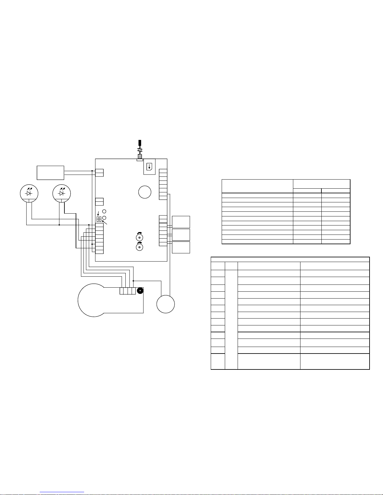
A.1) WIRING DIAGRAM
ANT1: Antenna
SMA: SMA Antenna connector
DLV1: GREEN Led “ON”
DLR2: RED Led “L INE”
TR1: Audio level from local phones to intercom
TR2: Audio level from intercom to local phones
JP5: Impedance regulation microphone
JP6: Impedance reegulation loudspeaker
SH1: GSM SIM Holder
PB1: 3V backup battery (CR2032) to keep RTC
CN1
1: + Power supply (12 Vdc)
2: - Power supply (Ground)
CN2
1 e 2: Telephone 1 “Pit”
3 e 4: Telephone 2 “Cabin Roof”
5 e 6: Telephone 3 “Engine Room”
7: Data line OUT
8: Data line IN
CN3
1 - 2: Contact “main alarm”
(cab in alarm)
3 - 4: Contact “alarm filter” or
Auxi liary alarm
5 - 6: Contact “Technologic 1” or
GONG
7 - 8: Contact “Technologic 2” or
GONG
CN4
1: Data OUT for battery LED
2: DatiaOUT for battery relay
CN5
1: Ground Intercom
2: Loudspeaker Intercom
3: Handsfree microphone
4: P/S microphone (12 Vdc)
5: Contact relay 1 NO
6: Contact relay 1 Common
7: Contact relay 2 NO
8: Contact relay 2 Common
8
7
6
5
4
3
2
1
CN3
CN2
1
2
3
4
5
6
7
8
CN5
1
2
CN4
1
2
CN1
8
7
6
5
4
3
2
1
SMA
SH1
PB1
DLR2
DLV1
TR2
TR1
JP6
ANT1
JP5
12Vdc
Loudspeaker
Microphone
Ground
Alarm
Button
Power supply
12Vdc / 500mA
+
-
INTERCOM
Alarm
Sent
lamp
+
-
Alarm
received
lamp
+
-
12Vdc 12Vdc
Cab Roof
Phone
Engine-
Room
Pit phone
For proper operation it is advisable to install
T.gsm at least 2 meters from electromagnetic
noise sources, switchgear, motors, power relays,
inverters and to use only new and dedicated cabling.
21
C.3.11) CALL IDENTIFICATION CODES
When the operator requests the System ID (by pres sing 4), T.gsm sends the 6 digit of the ID
(parameter “04”) and then the code corresponding t o the type of call active (3 dig it).
This coding is useful when managing T.gsm form an automated ca ll center.
It is possible, on demand, to customize the codes identify ing the type of the call. Please refer to
Teledif technical services.
Currently only two modes are ava ilable. The mode can be selected by setting para meter 11 (ref
section C.3.1, page 13).
Example: to select mode 2 set: 11 11 * 2 *.
C.3.12)
TELEPHONE DIRECTORY
TYPE OF CALL
DTMF TONE CODE
MODE 1
MODE 2
Main Alarm: CABIN *01
D13
Allarme manutentori: PIT *02
D13
Allarme manutentori: CABIN ROOF *03
D13
Allarme manutentori: ENGINE RO OM *04
D13
Allarme BATTRY *07
643
TECHNOLOGICAL Alarm 1 *12
*12
TECHNOLOGICAL Alarm 2 *13
*13
LOW CREDIT Alarm *30
*30
END OF ALARM *20
523
REMOTE DIAGNOSTIC *05
583
INCOMING CALL *31
*31
TELEPHONE DIRECTORY
PAR. VAL FUNCTION YOUR NUMBER
80
Max
20
digit
End of Alarm
81
1st number Main and Maintainer
Alarm
82 2nd number
83 3rd number
84 4th number
85 5th number
86 Technological alarm 1
87 Technological alarm 2
88 Remote diagnostic
89 Battery Alarm
90 Low Credit or SIM expiration alarm
91 Auxiliary Alarm
99
By using this function it is possible
to set in a single operation the
same number for all the alarms
and reports (from rel. SW 2.1)
 Loading...