

Teledif micro TSA 4.0 Instruction Manual

1
micro
TSA 4.0
Emergency Phone System
For Analog Line (POTS)
Or GSM gateway
Instruction Manual
English Ed. 1 del 04/07/2017
SW 1.1

2
THANKS TO CHOOSE
A TELEDIF ITALIA PRODUCT
To obtain the maximum performance and to use the features and functions of the micro TSA 4.0 in the best
way, read this manual carefully and keep it handy for any consultation.
Micro TSA 4.0 system is specifically designed to help, someone eventually locked in a cabin lift, to raise
an alarm to a service center.
Micro TSA 4.0 responds to the rules: Directive 95/16/EC, EN 81-28, EN 81-70, EN81-72, CTR 21;
EN 50082, EN 627 EN 50081-1:1991, EN55022, IEC EN139-4/A2: 2003, EN61000-4-2, EN61000-43, EN61000-4-4, EN61000-4-6,EN61000-4 -8.
Bi-directional (talk / listen)
Self-diagnosis. The main features are verified locally and remotely
Audio level programmable locally or remotely
Communication protocol to works with any call center via DTMF or Ademco Contact ID
2 Independent dial systems and communication: Cabin and Technician call
2-way communication from local phone and cabin
1 input for 3 working mode:
Main alarm filter
Gong signal
Technical alarm, with management of start and end of alarm
Warning message on/off
Calming message recordable by user
Location message
Messages identifying the type of alarm or warning and its origin
System information messages
Test call automatic and on request, programmable on days of calls
Low battery alarm, by programming the threshold level and duration of the test
Programmable alarms to be managed by: voice call, or CLI
Communication mode with call center
DC output for “alarm sent” and “alarm received” report
local and remote programming and verification, with the support of a in line vocal guide
10 telephone numbers associated with various types of alarm calls
TECHNICAL SPECIFICATIONS
Power supply: 1 2 Vdc
Max power consumption @ 12Vcc (RMS): ±150 mA
Min power consumption @ 12Vcc (RMS): ± 70 mA
Open collector outputs: to GND with max 0,5A current @ 12Vdc
Output voltage: 12Vdc not stabilized
Box size with connectors: 79 (L) x 195 (H) x 135 (P) mm
Connectors: Extractables
Weight: ± 70 g
Working temperature: From +1°C To +40°C
Storage temperature: From -20°C To +40°C
Operating and storage humidity: From 20% To 80%

3
INDICE
- A GENERIC WIRING DIAGRAM PAG. 4
- B WIRING DIAGRAM WITH TELEDIF COMPONENTS PAG. 5
- C.1 SELFTEST PAG. 6
- C.2 OPERATING PAG. 6
- C.2.1 EVENTS AND PRIORITY PAG. 6
- C.2.1.1 INTERCOM PAG. 6
- C.2.1.2 MAIN ALARM (CABIN) PAG. 7
- C.2.1.3 MAINTAINER ALARM PAG. 7
- C.2.1.5 BATTERY ALARM PAG. 7
- C.2.1.7 END OF ALARM PAG. 7
- C.2.1.8 TEST CALL (ROUTINE) PAG. 8
- C.2.1.9 INCOMING CALL PAG. 8
- C.2.1.10 ANSWER TO ALARM CALL PAG. 9
- C.2.2 SYSTEM ACCESS AND CONTROL CODES PAG. 9
- C.3 PROGRAMMING PAG. 10
- C.3.1 SYSTEM SETTINGS PAG. 11
- C.3.2 MAIN ALARM AND END OF ALARM PAG. 12
- C.3.3 MESSAGES PAG. 13
- C.3.4 TEST CALL PAG. 14
- C.3.5 BATTERY ALARM PAG. 14
- C.3.7 O.C. OUTPUTS PAG. 15
- C.3.7.1 “ALARM SENT” AND “ALARM RECEIVED” PAG. 16
- C.3.8 TELEPHONE NUMBERS PAG. 16
- C.3.9 CLI CALLS PAG. 16
- C.3.10 COMMUNICATIONS CODES PAG. 17
- C.4 ERRORS PAG. 18
- D FAQ: PAG. 18
QUICK START
To quickly install the MICRO TSA 4.0 and use its services do the following basic steps:
1. Open the plastic shell of MICRO TSA 4.0
2. Connect the telephone line to plug CN_TEL1 (two central contacts)
3. Connect the handset of the telephone (CN6 1:3)
4. Connect the alarm call button (CN3 1-2)
5. Connect the elevator car speakerphone (from-1 to CN5 CN5-4)
6. Feed the power supply to MICRO TSA 4.0, 12Vcc/500mA (CN1 1-2), matching the polarity.
7. Configure the MICRO TSA 4.0 from a local touch tone phone, program at least one emergency number (parameter "81" on page 15, or parameter 99 on page21)
8. Hang up the phone and wait for the red light stops flashing. If it begin to flash rapidly (like the green
led) pick up the handset intercom to hear the error message and refer to "C.4"
9. The system is ready to run when the green LED flashes rapidly and the red is off.
10. Break the appropriate notches for wires in the plastic cover.
11. Close the plastic shell of the MICRO TSA 4.0.
Note: Install the MICRO TSA 4.0 at least 2 meters away from possible sources of electromagnetic noise, always use new and specific cables (for hands-free intercom and phone, phone to phone line).
4
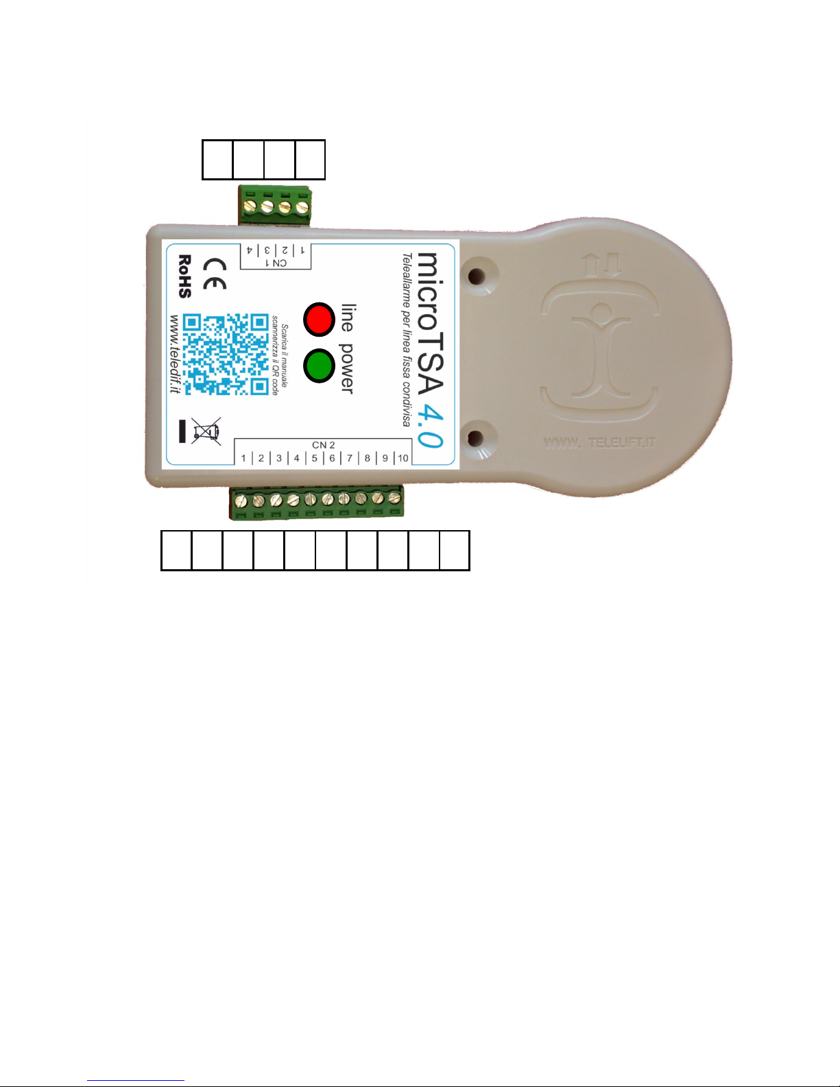
Link map
LV Green led (power)
LR Red led (line busy and test)
CN1
1 + Pwr
2 - Pwr
3 + 485
4 - 485
CN2
1 Local Phone A
2 Local Phone B
3 Alarm sent
4 Alarm received
5 12 Vcc not regulated not stabilized
6 Technical Alarm
7 Main Alarm
8 GND
9 Phone Line A
10 Phone Line B
1 2 3 4 5 6 7 8 9 10
CN2
4 3 2 1
CN1
5
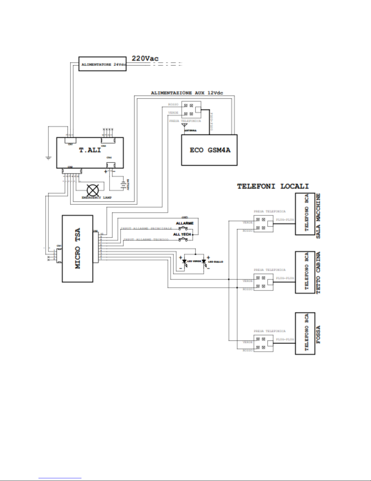
Installation kit sample
Sample of a tipical complete installation of micro TSA 4.0 with power supply ups T.ALI, and connected to a
gateway Echo GSM4

6
C) OPERATION
The micro TSA 4.0 system has 4 system conditions:
1. SELF-TEST
2. OPERATING
3. PROGRAMMING
4. ERROR (WARNING)
C.1) SELF-TEST
The condition of self-test is signaled by a slow flashing LED LINE (red).
When switched on, the micro TSA 4.0 automatically starts the self-test procedure to check the
minimum conditions for proper operation, such as:
1. The programming of at least one of the 5 numbers for the main alarm
2. The suitability of the supply voltage
3. The presence of the telephone line
The self-test procedure is performed whenever any of the following conditions:
Turn on of the system
Hanging up the phone after a cancellation or programming of telephone numbers for
main alarm
After an automatic or manual system reset
At the end of the self test, the red LED off indicates that the system is working correctly, the red
LED flashes quickly to indicate an error condition (see section C.4).
The system sends a test call (if the phone number is programmed) after the time defined in para-
meters 42 and 43. ( see section C.2.3.5).
Any error is reported also on alarm sent signal (pin 3 of connector CN2).
C.2) OPERATING
C.2.1) Events and priorities
The MICRO TSA 4.0 handles events and alarm signals in order of priority
1. ACCESS FROM LOCAL AND REMOTE PHONE, AFTER THE CHAR * PRESSED
2. MAIN ALARM (CAB) AND MAINTAINER ALARM
3. BATTERY ALARM
4. TECHNICAL ALARM
5. END OF ALARM (MAIN AND TECHNICAL)
6. ROUTINE CALL (TEST CALL)
The micro TSA 4.0 system always runs the first 2 events with higher priority (Event 1 has higher
priority than 2, etc.).
If a higher priority came during an event, the micro TSA 4.0 suspend the procedure in progress
to handle the new event and after handling the event will resume the event suspended.
C.2.1.1) Intercom
MICRO TSA 4.0 can connect multiple internal phones in parallel to the intercom system
From internal phones, you can:
Initiate End alarm procedure, if programmed
 Loading...