

Page 1
M SERIES
ANALOG CORDED
USER GUIDE
For M100B5, M100B10, M100BW5, M100BW10, M200B5,
M200B10, M200BW5, M200BW10
Page 2

Table of Contents
Section A
Unpacking Your Telephone ..........................3
Installation .......................................3
Caution Information .............................3
Connecting the Handset Cord .....................3
Connecting the Line Cord .........................3
Operation ........................................3
Placing a Call. . . . . . . . . . . . . . . . . . . . . . . . . . . . . . . . . . .3
Receiving a Call .................................3
Adjusting Ring Volume for Base ...................4
Adjusting Speakerphone Volume ...................4
Adjusting Handset Receiver Volume ................4
Redial .........................................4
Using the HOLD Key .............................4
Auto-Dial Keys—Faceplate Off .....................4
Conference (2-line models only) ...................4
Auto-Dial Keys—Faceplate On .....................5
Programming ................................5
Important Safety Instructions ........................6
Section B
Bluetooth User Instructions ........................10
Bluetooth Use Cases ..............................11
Wi-Fi Specifications ...............................11
Features ......................................11
WLAN ........................................11
Wireless Access Point User Instructions ..............11
Analog Guest Service Key Programming ..............12
Storing a Number into Memory Keys
or OneTouch Key ...............................12
Programming Flash Timing and Pause Timing ......12
Section C
1 Webpage Login ...............................13
1.1 Login Method .............................13
1.1.1 Login via Router (WAN Port) .............13
1.1.2 Login via Wi-Fi or LAN Port ..............13
1.2 Login ....................................13
1.3 Homepage ................................13
1.3.1 Operation State ........................14
1.3.2 Setup Wizard ..........................14
1.4 Operation Mode ...........................16
1.4.1 Bridge Mode ..........................16
1.4.2 Gateway Mode .........................16
1.4.3 Wireless Client Mode ...................16
2 Network Setup ................................16
2.1 LAN Setup ................................16
2.2 WAN Setup ...............................17
2.2.1 Static IP ..............................18
2.2.2 Dynamic IP ...........................18
2.2.3 PPPoE ...............................18
2.3 MAC Address Clone ........................19
3 Wireless Parameters Setup .....................19
3.1 Basic Setup ...............................19
3.2 Security Setup ............................20
3.2.1 WEP .................................21
3.2.2 WPA-PSK/WPA2-PSK—Wi-Fi
Protected Access ............................22
3.2.3 WPA/WPA2 ...........................23
3.3 Advanced Setting ..........................24
3.4 WPS .....................................26
3.5 Station List ...............................26
4 DHCP Server .................................26
4.1 DHCP Service .............................26
4.2 Client List ................................27
4.3 Static Address Assignment ..................27
5 Security Setting ...............................28
5.1 MAC/IP/Port Filtering ......................28
6 Routing Function ..............................28
7 System Tools .................................29
7.1 Change Login Password ....................29
7.2 Language Setting ..........................30
7.3 Time Setting ..............................30
7.4 Upgrade Firmware .........................31
7.5 Recover Factory Set ........................31
7.6 Back and Load the Configuration .............32
7.7 Dynamic DNS .............................32
7.8 Restart the System .........................33
7.9 System Log ...............................33
Section D
Guest Card Samples ..............................34
2 www.teledex.com M SERIES ANALOG CORDED USER GUIDE
Page 3

Section A
Operation
PLACING A CALL
Using the handset:
Unpacking Your Telephone
This package should contain the following:
• Handset
• Base Unit
• AC Adapter
• 10 foot handset coil cord
• 15-foot, 4-wire RJ-14 Line Cord
• 15-foot, 8-wire RJ-45 Cable
• Fixed Plastic template
Installation
CAUTION INFORMATION
• Never install telephone or network wiring
during a lightning storm.
• Never install telephone or Ethernet jacks in
wet locations unless the jack is specifically
designed for wet locations.
• Never touch uninstalled telephone wires or
terminals unless the telephone line has been
disconnected at the network interface.
• Use caution when installing or modifying
telephone and network lines.
CONNECTING THE HANDSET CORD
1. Pick up the handset and select either
line1 or line 2. Listen for dial tone and dial
the desired number.
2. After the call is complete, press the key for
the selected line again to end the call.
Using the speakerphone:
1. Press key for either line 1 or line 2, or
press SPKR.
2. Listen for dial tone, and dial the desired
number, or press an auto dial key to dial a
preprogrammed number.
3. After the call is complete, press the SPKR
key to end call.
RECEIVING A CALL
An audible ring and flickering red LED indicate
an incoming call. To answer the call using the
handset while it is not on the base:
1. Pick up the handset.
2. Press the line key for the ringing line.
3. To end the call, place the handset in the
base unit cradle.
To answer the call using the handset while it is
resting on the base:
A 10 ft. modular handset coil cord is provided.
To install, simply plug one end of the coil cord
into the jack at the base of the handset and the
other end into the jack located on the end of the
telephone base marked Handset.
CONNECTING THE LINE CORD
A 15 ft. modular line cord is provided. To install,
simply plug one end of the cord into the modular
jack at the top end of the base unit and the other
end into the wall jack.
M SERIES ANALOG CORDED USER GUIDE www.teledex.com 3
1. Pick up the handset from the base. The
phone will automatically connect to the
correct ringing line.
2. To end the call, replace the handset in the
base unit cradle.
To answer the call using the speakerphone:
1. Press the line key for the ringing line. The
speakerphone will go off-hook, answering
the ringing line.
2. Or press the SPKR key. The phone will
automatically select the correct, ringing line.
3. To end the call, press the SPKR key again.
Page 4

ADJUSTING THE RING VOLUME FOR BASE
To change phones after placing a call on hold:
The up and down volume keys will adjust the
ringer volume of the telephone. The M Series
telephone begins at the lowest setting, then
automatically rings louder with each successive
ring during an incoming call.
The speakerphone has five (5) levels. To adjust
ring volume, locate the volume up/down keys,
located on the front surface of the phone to the
right of the keypad.
ADJUSTING SPEAKERPHONE VOLUME
The speakerphone has five (5) levels. To adjust
speakerphone volume, locate the volume up/
down keys, located on the front surface of the
phone right of the keypad.
ADJUSTING HANDSET RECEIVER VOLUME
The handset has five (5) volume levels. To adjust
the handset volume, locate the volume up/down
keys. Pressing the down key will decrease the
volume level, while pressing the up key will
increase it.
REDIAL
The M Series can automatically redial the last
number dialed. Lift the handset or turn on the
speaker phone then press the REDIAL key to
redial the last number.
USING THE HOLD KEY
The HOLD key places the call on hold locally at
the M Series telephone.
With a call active, press the HOLD key on either
line to remove a call from hold:
1. Press the line key of the call on hold. This
will remove the call from hold, making the
call active again.
2. The red LED will return to blinking
illumination, indicating the line is active.
1. Place the call on hold as above.
2. Pick up the call at another telephone that
is on the same line. The telephone will
activate the line and remove the hold at
the original telephone.
TO MUTE THE SPEAKERPHONE
1. Press the MUTE key on the base unit.
The red LED above the MUTE key will
illuminate. The party on the other end will
not be able to hear you when the MUTE
LED is lit.
2. Press the MUTE key again to turn off the
mute feature. The MUTE LED will go out.
AUTODIAL KEYSFACEPLATE OFF
The M Series has either five (5) or ten (10)
programmable guest service (auto-dial) keys,
depending on the model you own.
These keys can be programmed to automatically
dial telephone numbers, or to activate telephone
system features. To program the auto-dial keys
(programming can only be done from base unit):
1. With the phone on hook (inactive) and
the fixed faceplate removed, press the
recessed STORE key.
2. Enter the desired telephone number (up to
32 digits in length) to be stored. To enter
a pause in the number string, press the
REDIAL key as necessary.
3. Press the STORE key again.
4. Press the auto-dial key where the number
is to be stored. Programming is now
completed for that auto dial key.
To program additional keys, repeat this process.
CONFERENCE (2LINE MODELS ONLY)
The CONF key allows for three-way conversations.
Depending on the situation, you may initiate a
conference call using one of these methods:
4 www.teledex.com M SERIES ANALOG CORDED USER GUIDE
Page 5

User initiates two calls:
PROGRAMMING
1. Place call to first party, then place them on
hold by pressing the HOLD key.
2. Using the second line, place call to second
party. Then put them on hold by pressing
the HOLD key.
3. Activate the 3-way conference call by
pressing HOLD/CONF key on the base unit.
User initiates one call:
1. After receiving a call from first party, place
them on hold as above.
2. Using the second line, place call to second
party. Then put them on hold as above.
3. Activate the 3-way conference call by
pressing CONF key on the base.
User includes two callers:
1. After receiving a call from first party, place
them on hold as above.
2. After receiving call from second party,
place them on hold as above.
3. Activate the 3-way conference call by
pressing CONF key on the base.
Storing a Number into Memory Keys or OneTouch
Message-Waiting Key.
Each location can store up to 32 digits in tone
mode.
Note: A Pause or Flash programmed into memory
counts as one digit when storing a number.
1. Set the Speakerphone in the OFF mode
(inactive).
2. Press *#79*# + number + M(n) Enter the
number to be stored using the numeric
dial pad (that is, *#79*# +123456+M1). The
phone will generate “a Di-Du” sound.
3. If additional numbers are to be stored,
repeat steps 2 through 3.
Programming Flash Timing and Pause Timing.
Flash timing options are 100 mS through 1000mS,
programmable in 10 0mS increments.
• The default Flash timing is 600 mS.
• Pause timing options are 1.0 s through 5.0 s.
The default Pause timing is 3.6 s.
To terminate a conference call, pressing a line
key will maintain the connection with that line,
while dropping the other line. To terminate the
call entirely, place the handset back into the
cradle to disconnect both parties.
AUTODIAL KEYSFACEPLATE ON
The M Series has either five (5) or ten (10)
programmable guest service (auto-dial) keys,
depending on the model you own.
These keys can be programmed to automatically
dial telephone numbers, or to activate telephone
system features. To program the auto-dial keys
(programming can only be done from base unit):
Programming Flash Timing.
1. Set the Speakerphone in the OFF mode
(inactive).
2. Press *#78*# + number (1-0) + Conf (the
phone will generate a “Di-Du” sound after
the setting is finished) (that is, *#78*# + 9
+ Conf - Flash = 900 ms).
Programming Pause Timing.
3. Set the Speakerphone in the OFF mode
(inactive).
4. Press *#78*# + number (1-5) + Redial (the
phone will generate a“Di-Du” sound after
the setting is finished) (that is, *#78*# + 5
+ Redial – Pause = 5 seconds).
M SERIES ANALOG CORDED USER GUIDE www.teledex.com 5
Page 6

Important Safety Instructions
When using your telephone equipment, basic
safety precautions should always be followed to
reduce the risk of fire, electric shock, and injury
to persons, including the following:
1. Read and understand all instructions.
2. Follow all warnings and instructions marked
on the product.
3. Unplug the product from the wall outlet
before cleaning. Do not use liquid cleaner
or aerosol cleaners. Use a damp cloth for
cleaning.
4. Do not use this product near water—for
example, near a bathtub, wash bowl,
kitchen sink or laundry tub, in a wet
basement, or near a swimming pool.
5. Do not place this product on an unstable
cart, stand, or table. The product may fall,
causing serious damage to the product.
6. Slots and openings in the cabinet and
the back or bottom are provided for
ventilation, to protect it from overheating.
These openings must not be blocked or
covered. The openings should never be
blocked by placing the product on the bed,
sofa, rug, or any other similar surface.
This product should never be place near
or over a radiator or heat register. This
product should not be placed in a built-in
installation unless proper ventilation is
provided.
7. Never push objects of any kind into this
product through cabinet slots as they may
touch dangerous voltage points or short
out parts that could result in a risk of fire
or electric shock. Never spill liquid of any
kind on the product.
8. To reduce the risk of electric shock do
not disassemble this product. Take it to a
qualified service facility if service or repair
work is required. Opening or removing
covers may expose you to dangerous
voltages or other risks. Incorrect
reassembly can cause electric shock when
the appliance is subsequently used.
9. Unplug this product from the wall outlet
and refer servicing to qualified service
personnel under the following conditions:
– When the power supply cord or plug is
damaged or frayed.
– If liquid has been spilled into the
product.
– If the product has been exposed to rain
or water.
– If the product does not operate normally
by following the operating instructions.
Adjust only those controls that are
covered by the operating instructions, as
improper adjustment of other controls
may result in damage and may require
extensive work by a qualified technician
to restore the product to normal
operation.
– If the product has been dropped or the
cabinet has been damaged.
– If the product exhibits a distinct change
in performance.
10. Avoid using a telephone (other than a
cordless type) during an electrical storm.
There may be a remote risk of electric
shock from lightning.
11. Do not use the telephone to report a gas
leak in the vicinity of the leak.
PLEASE SAVE THESE INSTRUCTIONS.
FCC Interference Information
This device complies with Part 15 of the FCC
Rules. Operation is subject to the following two
conditions:
1. This device may not cause harmful
interference.
2. This device must accept any interference
received, including interference that may
cause undesired operation.
6 www.teledex.com M SERIES ANALOG CORDED USER GUIDE
Page 7

This equipment has been tested and found to
comply with the limits for a Class B digital device,
pursuant to Part 15 of the FCC Rules. These limits
are designed to provide reasonable protection
against harmful interference in a residential
installation. This equipment generates, uses,
and can radiate radio frequency energy and, if
not installed and used in accordance with the
instructions, may cause harmful interference
to radio communications. However, there is no
guarantee that interference will not occur in a
particular installation.
If this equipment does cause harmful interference
to radio or television reception, which can be
determined by turning the equipment off and on, the
user is encouraged to try to correct the interference
by one or more of the following measures:
– Reorient or relocate the receiving antenna
for the radio or television that is receiving the
interference).
– Reorient or relocate and increase the
separation between the telecommunications
equipment and receiving antenna.
– Connect the telecommunications equipment
into an outlet on a circuit different from that to
which the receiving antenna is connected.
FCC RF Radiation Exposure
Statement
The installation of the base unit should allow
at least 20 centimeters between the base
and persons to be in compliance with FCC RF
exposure guidelines. For body-worn operation,
the portable part (handset) has been tested and
meets FCC RF exposure guidelines.
This device must not be co-located or operating
in conjunction with any other antenna or
transmitter. The changes or modifications not
expressly approved by the party responsible for
compliance could void the user’s authority to
operate the equipment.
Industry of Canada Requirements
Note: This equipment meets the applicable
Industry Canada Terminal Equipment Technical
Specifications. This is confirmed by the
registration number. The abbreviation, IC, before
the registration number signifies that registration
was performed based on a Declaration of
Conformity indicating that Industry Canada
technical specifications were met. It does not imply
that Industry Canada approved the equipment.
Before installing this equipment, users should
ensure that it is permissible to be connected to
the facilities of the local telecommunications
company. The equipment must also be installed
using an acceptable method of connection. The
customer should be aware that compliance with
the above conditions may not prevent degradation
of service in some situations.
Repairs to certified equipment should be
coordinated by a representative designated by the
supplier. Any repairs or alterations made by a user
to this equipment, or equipment malfunctions,
may give the telephone communications company
cause to request the user to disconnect the
equipment.
Users should ensure for their own protection, that
the electrical ground connections of the power
utility, telephone lines, and internal metallic
water pipe system, if present, are connected
together. This precaution may be particularly
important in rural areas.
Caution: Users should not attempt to make such
connections themselves, but should contact
the appropriate electric inspection authority, or
electrician, as appropriate.
Notice: The Ringer Equivalence Number (REN)
assigned to each terminal device provides an
indication of the maximum number of terminals
allowed to be connected to a telephone interface.
The termination on an interface may consist
M SERIES ANALOG CORDED USER GUIDE www.teledex.com 7
Page 8

of any combination of devices subject only to
the requirement that the sum of the Ringer
Equivalence Numbers of all the devices does not
exceed 5.
REN: Z
For warranty and service in Canada, please
contact:
Williams Telecommunications
5610 Kennedy Road
Mississauga, Ontario, L4Z2A9
Canada
Phone: 905-712-4242
Fax: 905-712-1754
Requirements of Part 15—
FCC Rules
Note: This equipment has been tested and found to
comply with the limits for a Class B digital device,
pursuant to Part 15 of the FCC Rules. These limits
are designed to provide reasonable protection
against harmful interference in a residential
installation. This equipment generates, uses,
and can radiate radio frequency energy and, if
not installed and used in accordance with the
instructions, may cause harmful interference
to radio communications. However, there is no
guarantee that interference will not occur in a
particular installation. If this equipment does
cause harmful interference to radio or television
reception, which can be determined by turning
the equipment off and on, the user is encouraged
to try to correct the interference by one or more
of the following measures:
1. Move the telephone away from the
receiver.
2. Consult the dealer or an experienced
radio/TV technician for help.
Any changes made by the user not approved by
the manufacturer can void the user’s authority to
operate the telephone.
Requirements of Part 68—
FCC Rules
This equipment complies with Part 68 of the FCC
Rules and the requirements adopted by ACTA.
On the bottom of this telephone is a label that
contains, among other information, a product
identifier in the format US:AAAEQ##TXXXX. If
requested, this number must be provided to
the telephone company. The USOC Jack for this
equipment is RJ11C.
A plug and jack used to connect this equipment
to the premises wiring and telephone network
must comply with the applicable FCC Part 68
rules and requirements adopted by ACTA. A
compliant telephone cord and modular plug are
provided with this telephone. It is designed to be
connected to a compatible modular jack that is
also compliant. See installation instructions for
details.
The Ringer Equivalence Number (REN) is used
to determine the number of devices that may be
connected to a telephone line. Excessive RENs
on a telephone line may result in the devices
not ringing in response to an incoming call. In
most but not all areas, the sum of RENs should
not exceed five (5.0). To be certain of the number
of devices that may be connected to a line, as
determined by the total RENs, contact the local
telephone company. For products approved after
July 23, 2001, the REN for this product is a part
of the product identifier that has the format
US:AAAEQ##TXXXX. The digits represented by
## are the REN without a decimal point (e.g., 03
is a REN of 0.3). For earlier products, the REN is
separately shown on the label.
If this telephone causes harm to the telephone
network, the telephone company will notify you
in advance that temporary discontinuance of
service may be required. But if advance notice is
not practical, the telephone company will notify
8 www.teledex.com M SERIES ANALOG CORDED USER GUIDE
Page 9

the customer as soon as possible. Also, you will
be advised of your right to file a complaint with
the FCC if you believe it is necessary.
The telephone company may make changes in its
facilities, equipment, operations, or procedures
that could affect the operation of the equipment.
If this happens, the telephone company will
provide advance notice in order for you to
make the necessary modifications to maintain
uninterrupted service.
These telephone devices are intended for
commercial use only, primarily in hotel guestrooms.
They must be used with a PBX (private branch
exchange), and are not intended to be connected
directly to a PSTN line (public switched telephone
network). There are no user-serviceable parts
inside the equipment.
Technical Specifications
DIMENSIONS
If trouble is experienced with this equipment, for
repair or warranty information, please contact
Teledex at (800) 462-9446. If the equipment is causing
harm to the telephone network, the telephone
company may request that you disconnect the
equipment until the problem is resolved.
There are no user-serviceable parts contained in
this equipment.
Connection to party line service is subject to
state tariffs. Contact the state public utility
commission, public service commission, or
corporation commission for information.
If your home has specially wired alarm equipment
connected to the telephone line, ensure the
installation of this product does not disable your
alarm equipment. If you have questions about
what will disable alarm equipment, consult your
telephone company or a qualified installer.
This telephone is hearing aid compatible.
5.8” (w) x 8.56” (l) x 3.64” (h)
WEIGHT
With handset: 3.3 lbs.
User Guides
If additional User Guides are needed, please go
to www.teledex.com to download the PDF.
Service
When problems arise that cannot be resolved
using this or related documents, please go to
www.teledex.com/support for information about
customer support, technical support, warranty,
and product returns.
Statement of Limited Warranty
Teledex product warranty information is available
at www.teledex.com.
M SERIES ANALOG CORDED USER GUIDE www.teledex.com 9
Page 10

Section B
Bluetooth User Instructions
1. Register a Bluetooth-Enabled Mobile
Phone to the M Series Phone
1.1 In standby mode, press and hold
key for 3 seconds, the Bluetooth LED
will blink and the speaker will generate
a “toot” prompt tone, the terminal then
enters the registration state.
1.2 The mobile phone turns on Bluetooth
and selects the corresponding
device connection. After successfully
registering, the Bluetooth LED turns off,
returning the phone to standby mode.
Note:
1. One M Series terminal can
register only one mobile phone.
2. During the registration, escape
the registration process by taking
the handset off-hook.
2. Deregister the Mobile Phone
In the standby mode, press and hold
key for 3 seconds, the speaker generates
a “toot” prompt tone, the terminal will
automatically delete the registered mobile
phone.
Note: When the mobile phone turns
off Bluetooth or exceeds the supported
distance (range of about 30 ft/10 meters),
the M series terminal will automatically
delete the registered mobile phone within
15 seconds.
3. Play Bluetooth Audio
The mobile phone turns on the music
player. The M Series terminal can carry
out the following operations:
1. Press uto start/stop the play.
2. Press to increase the sound volume.
3. Press to decrease the sound volume.
4. Press to select the previous music,
press to select the next music.
Note: During the play, the Bluetooth LED
automatically blinks.
4. How to Use a Bluetooth Phone
4.1 Placing a Call by Bluetooth
Placing a Call: Lift the handset and
press key, the Bluetooth LED lights
up. The handset receiver generates the
dial tone and you can dial the telephone
number. The mobile phone will
automatically dial out the number after
3 seconds or you can directly press #
key to start dialing out.
4.2 Receiving a Call by Bluetooth
When the mobile phone rings, lift the
handset and press key to answer
the call.
5. Set the Name of the M Series Phone/
Bluetooth Device
In the standby mode, press * # 2 8 <name>
* # . The <name> only supports numerals up
to 8 digits.
Example: Pressing * # 2 8 2222 * # would
change the name of the M Series bluetooth
interface to 2222.
10 www.teledex.com M SERIES ANALOG CORDED USER GUIDE
Page 11

Bluetooth Use Cases
iOS Devices iOS Method Android Devices Android Method
Place call from
iPhone—speak over
M Series phone
Receive call to iPhone
speak over paired
MSeries phoneset
Play music over
paired iPhone device
through MSeries
speakers
Hear iPhone clock
alarm on M Series
phone
1. Place call from iPhone.
2. Press Bluetooth key on M Series
phone.
3. Lift handset of M Series phone or use
speaker.
1. A caller dials guest’s iPhone.
2. Both phones ring (iPhone AND
MSeries).
3. Pick up M Series handset to complete
call.
1. Pair device by pressing the MSeries
bluetooth button.
2. In iPhone Settings > Bluetooth select
the MSeries device number.
3. Play music.
iPhone does not allow for alarm to play
over external device
Place call from
Android—speak over
MSeries phone
Receive call to
Android speak over
paired MSeries
phoneset
Play music over
paired Android device
through MSeries
speakers
Hear Android clock
alarm on MSeries
phone
1. Place call from Android phone.
2. Press Bluetooth key on M Series
phone.
3. Lift handset of M Series phone or use
speaker.
1. A caller dials guest’s Android phone.
2. Both phones ring (Android AND
MSeries).
3. Pick up M Series handset to complete
call.
1. Pair device by pressing the M Series
bluetooth button.
2. In Android Phone Settings > Bluetooth
select the M Series device number.
3. Play music.
1. Pair Android device to M Series phone.
2. Both Android and M Series alarms will
sound. Android is Master device.
Wi-Fi Specifications
FEATURES
• Wireless 802.11n Access Point—up to
300Mbps
• 1 LAN Port and 1 WAN Port (RJ45)
• Browser-Based Interface for Configuration
and Management: OS Independent and Easy
to Use
• Support Telnet and CLI Command to Access
Wireless AP
• Full Wireless Security—WEP, WPA, WPA2
• Includes A2DP for audio streaming. Class 2
type range 10meters.
WLAN
• IEEE 802.11n, Backward Compatible with
802.11g/b
• 64, 128-bit Wired Equivalent Privacy (WEP)
Data Encryption
• 11 Channels (US, Canada)/13 Channels
(Europe)/14 Channels (Japan)
• IEEE 802.1x
• Software Upgrade Via HTTP
Wireless Access Point User
Instructions
Apply power to the M Series phone with the
provided PSU (Power Supply Unit). The phone’s
optional Wi-Fi unit will boot up in the default
“Gateway” mode. Search for the Wi-Fi SSID
(Service Set Identifier) from the phone (SY_LINK_
xxxxxx) and connect to it via Wi-Fi. (The default
SSID of SY_LINK_xxxxxx is a useful identifier, with
_xxxxxx representing the last 6 digits of the Wi-Fi
unit’s MAC address.) Once connected to the WiFi unit, you may then browse to 192.168.1.1 and
login using the default credentials admin/admin.
At this point you are able to configure the phone’s
Wi-Fi module through it’s web interface. You will
likely change the Operation Mode from Gateway
to Bridge Mode, in order to use your existing
network’s DHCP server to assign IP addresses.
You may also decide to change the SSID. If so,
make note of the MAC address, so that you may
easily find the the Wi-Fi unit’s new IP address in
your network’s DHCP lease tables.
M SERIES ANALOG CORDED USER GUIDE www.teledex.com 11
Page 12

Analog Guest Service Key
PROGRAMMING FLASH TIMING
Programming
STORING A NUMBER INTO MEMORY
KEYS OR ONETOUCH KEY
Each location can store up to 32 digits in tone
mode.
Note: A “Pause” or “Flash” programmed into
memory counts as one digit when storing a number.
1. Set the Speakerphone in the OFF mode
(inactive).
2. Press *#79*# + number + M(n). Enter the
number to be stored using the numeric
dial pad (that is, *#79*# + 123456 + M1).
The phone will generate “Di-Du” sound.
3. If additional numbers are to be stored,
repeat steps 2 through3.
PROGRAMMING FLASH TIMING AND
PAUSE TIMING
1. Set the Speakerphone in the OFF mode
(inactive).
2. Press *#78*# + number (1-0) + Conf.
The phone will generate “Di-Du” after the
setting is complete (that is, *#78*# + 9 +
Conf - Flash = 900 ms).
PROGRAMMING PAUSE TIMING
3. Set the Speakerphone in the OFF mode
(inactive).
4. Press *#78*# + number (1-5) + Redial.
The phone will generate “Di-Du” after the
setting is complete (that is, *#78*# + 5 +
Redial – Pause = 5 s).
Note: Use step 2 when programming Flash. Use
step 4 when programming Pause.
Flash timing options are 100 mS through 1000mS,
programmable in 100 mS increments.
• The default Flash timing is 600 mS.
• Pause timing options are 1.0 s through 5.0 s.
The default Pause timing is 3.6 s.
12 www.teledex.com M SERIES ANALOG CORDED USER GUIDE
Page 13

Section C
1 Webpage Login
1.1 Login Method
1.1.1 LOGIN VIA ROUTER (WAN PORT)
The WAN port has a dynamic IP. The user needs to seek the IP address of the WAN port of this phone
through the front router and then login via the IP address.
1.1.2 LOGIN VIA WIFI OR LAN PORT
Login to the default IP address of the LAN port of the phone, or easier still, search for the Wi-Fi SSID
that has been registered with the phone and connect to it. Then browse to the default IP address of
192.168.1.1 to be presented with the login screen.
1.2 Login
Both the initial username and password are admin. Input the username and password of admin/admin,
click Sign in, and enter the system. At this point you are able to begin configuring the phone’s optional
Wi-Fi module.
1.3 Homepage
M SERIES ANALOG CORDED USER GUIDE www.teledex.com 13
Page 14

1.3.1 OPERATION STATE
Shows the state information of the device.
System information: Software version, normal running time of system, and operation mode.
Internet configuration: The connection manner of current WAN, IP address, subnet mask, gateway,
DNS server, and MAC address.
LAN: The IP address of current LAN port, subnet mask, and MAC address.
1.3.2 SETUP WIZARD
The wizard mode helps you properly setup your WAN.
Step 1: Configure the Internet connection, click “Next” to access the WAN mode option.
14 www.teledex.com M SERIES ANALOG CORDED USER GUIDE
Page 15

Static IP address mode: Fill in your IP address, subnet mask, default gateway, and DNS server address
assigned by the network provider.
PPPOE dialing mode: Fill in your login account and password offered by the network provider. Select
the connection mode.
Now the WAN configuration is finished. Next, configure the wireless security setting.
Step 2: Here the network name (SSID) can be changed per your preference. The selection of safe
mode depends on your own actual demand. The analysis for safe mode has been noted in the following
Wireless Parameters–Security Setup.
M SERIES ANALOG CORDED USER GUIDE www.teledex.com 15
Page 16
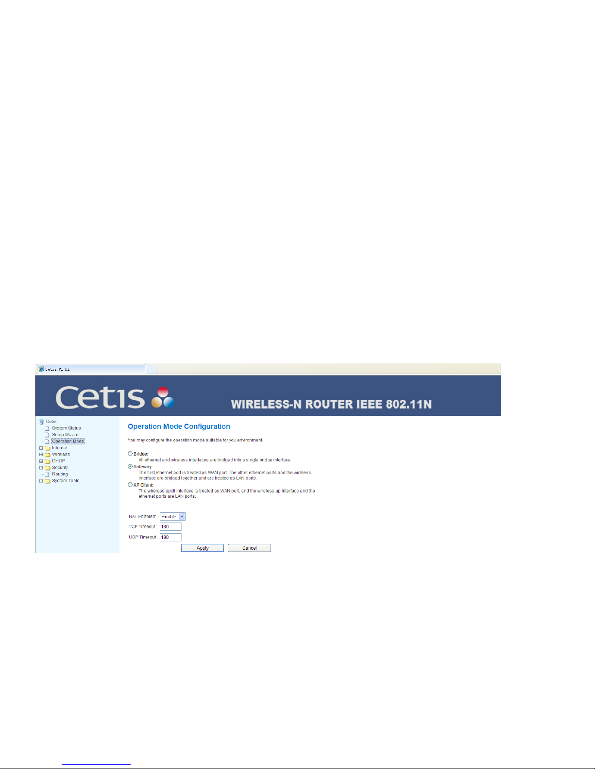
1.4 Operation Mode
1.4.1 BRIDGE MODE
This mode has the wired access and wireless access.
Wired access: The option “Enable Wireless Client” is disabled. Use the net cable to connect WAN port,
user’s modem, or Ethernet interface and LAN port to bridge the wireless client to acquire the IP address
of external network.
Wireless access: The option “Enable Wireless Client” is enabled. Set the Wireless Client menu in
“Wireless Network Setting” to connect another AP, LAN port and WAN port to bridge the wireless client
to acquire the IP address assigned by external network.
1.4.2 GATEWAY MODE
Wired access: Use the net cable to connect WAN port, user’s modem, or Ethernet interface and LAN
port at the wireless client to acquire the IP address assigned by the equipment gateway.
1.4.3 WIRELESS CLIENT MODE
Wireless access: Set the Wireless Client menu in “Wireless Network Setting” to connect another AP,
LAN port and WAN port at the wireless client to acquire the IP address assigned by the equipment
gateway.
2 Network Setup
2.1 LAN Setup
IP address: The IP address of the gateway against LAN. The factory set is 192.168.1.1 which could be
changed at your request. If you have changed the IP address, you must use the new IP address to login
16 www.teledex.com M SERIES ANALOG WIFI MODEL USER GUIDE
Page 17
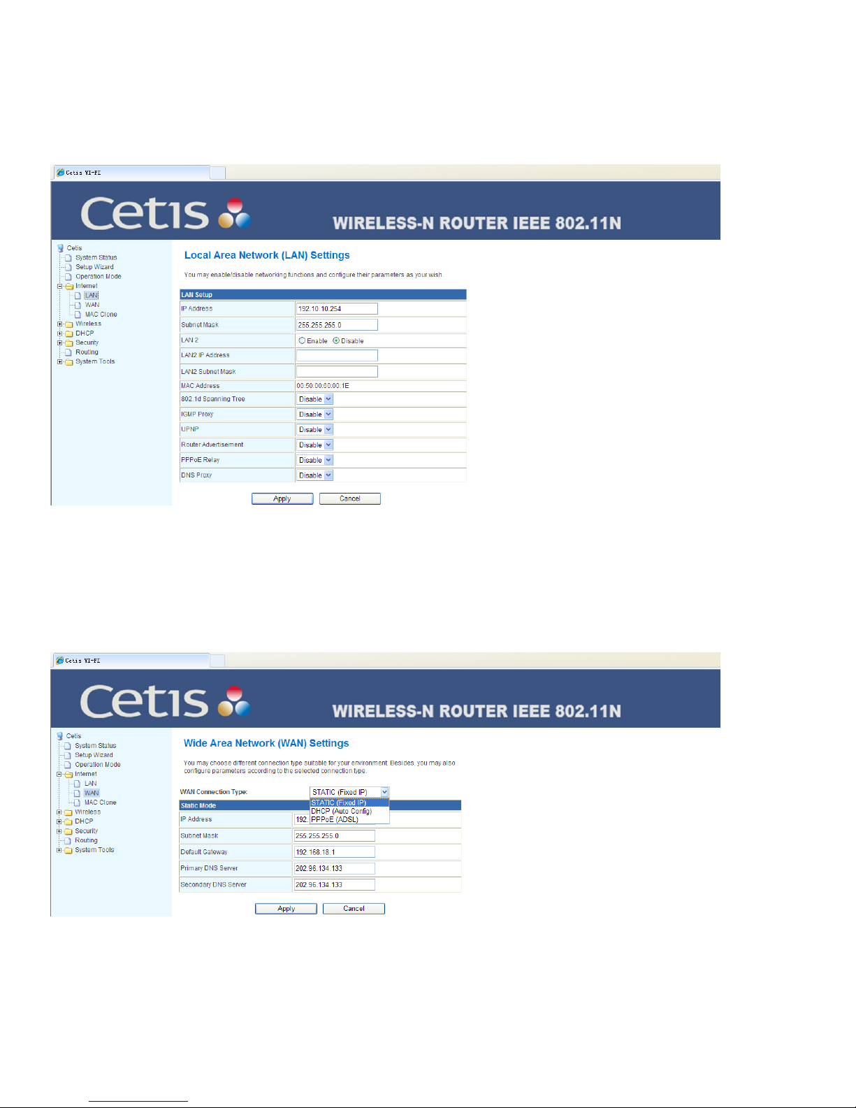
the gateway for WEB interface configuration. Moreover, the default gateway of all computers within the
LAN must be set to have this IP address for going online.
Subnet mask: The subnet mask of the gateway against LAN. Usually the default is 255.255.255.0.
MAC address: The MAC address of the gateway against LAN. The value cannot be changed.
2.2 WAN Setup
The user can select the connection manner according to the use environment. The Wide Area Network
has 5 available modes for selection: static (fixed IP), dynamic (auto-obtain), and PPPoE (ADSL) as well
as L2TP and PPTP. Each mode can configure the corresponding parameters.
M SERIES ANALOG CORDED USER GUIDE www.teledex.com 17
Page 18

2.2.1 STATIC IP
If the network operator provides you with the fixed IP, gateway, and DNS address, please select the
static (fixed IP) mode, click the Apply button to finish the setting.
2.2.2 DYNAMIC IP
If the network operator provides you with the dynamic IP address, please select the dynamic (auto
obtain) mode, click Apply button to finish the setting.
2.2.3 PPPOE
If the network operator provides you with the login account and account, please select the PPPoE (ADSL)
mode and properly fill them, click Apply button to finish the setting.
18 www.teledex.com M SERIES ANALOG CORDED USER GUIDE
Page 19
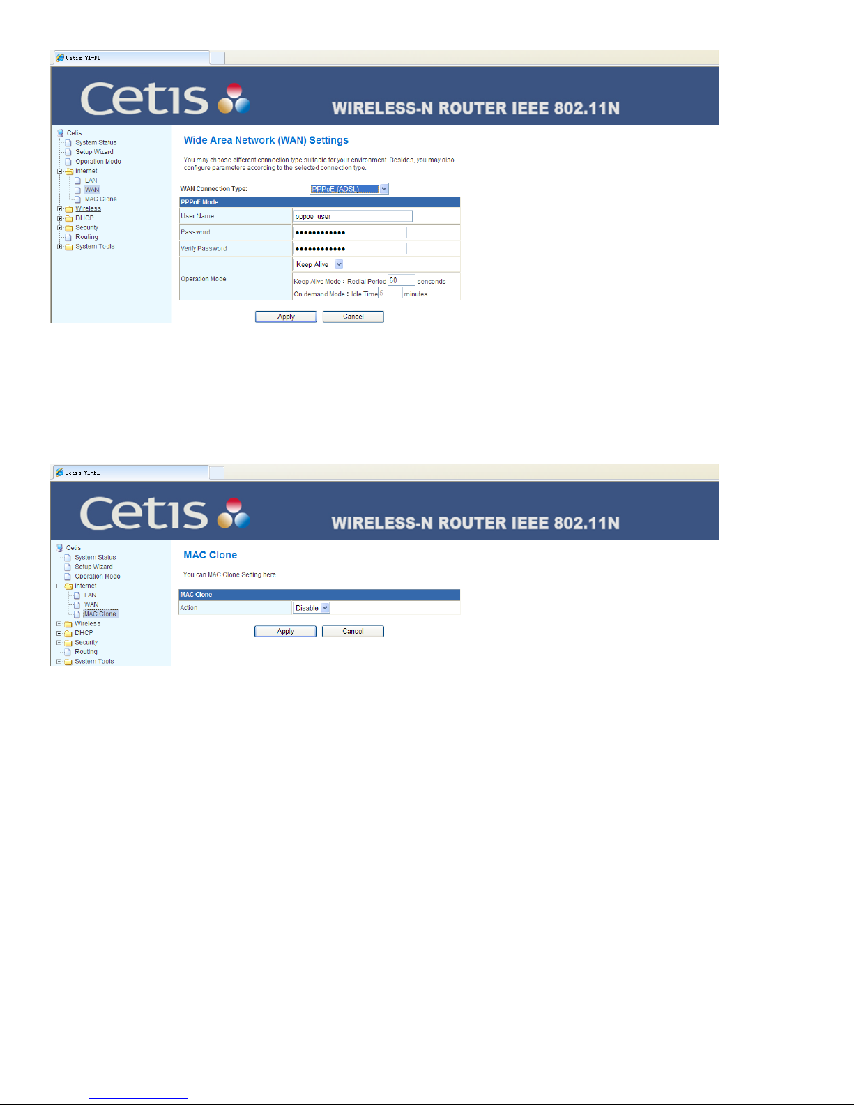
2.3 MAC Address Clone
Cloning the MAC address. Emulating/changing a MAC address can be necessary in some cases to
keep an Internet connection working. Usually this happens when exchanging a new device for the one
originally assigned for use by the ISP (Internet Service Provider).
3 Wireless Parameters Setup
3.1 Basic Setup
Wireless network switch: After turning Wi-Fi Off, the wireless network cannot be used. To use the
wireless function, the option must be enabled.
Mode: Set the wireless operation mode, there are five modes of 11b/g mixed mode, 11b only, 11g only,
11b/g/n mixed mode and 11n only (2.4G) etc. for selection. It’s recommended to use 11b/g/n mixed mode.
Network name: Can be changed to use for labeling the wireless network which will be shown in the
list of wireless networks sought by wireless network card. It’s recommended to change it into another
name for recognition. Several options can be set.
M SERIES ANALOG CORDED USER GUIDE www.teledex.com 19
Page 20
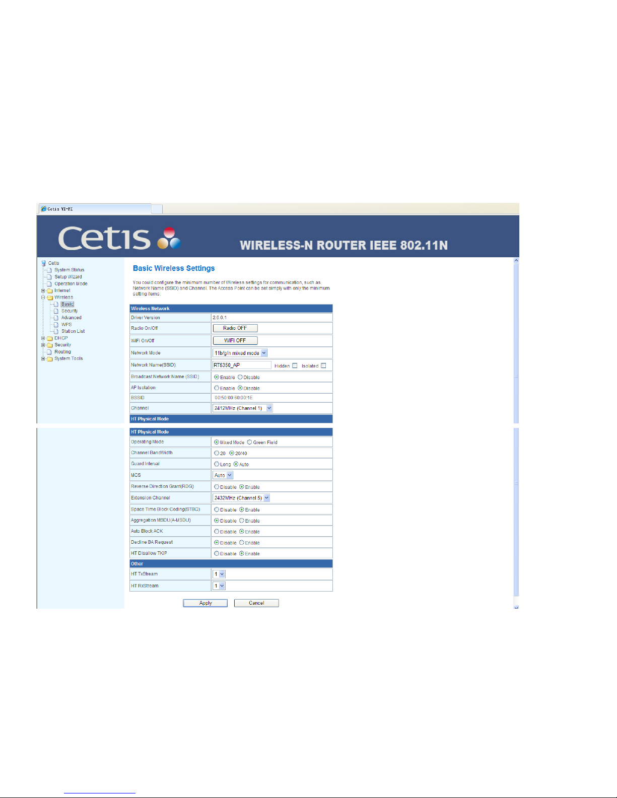
Broadcast network name: The gateway will not broadcast its own network name to the wireless base
unit once again. If there is any request of wireless connection, you need to manually fill the network
name.
AP isolation: The isolation of every other wireless AP (Access Point).
Frequency (channel): Takes the radio signal as the data signal delivering path for transmission medium,
the selection scope is 1–14. If you select Auto, the AP will select the best possible channel according to
the environment.
Channel bandwidth: Set the channel bandwidth seized when delivering the wireless data. The options
are 20M and 20M/40M.
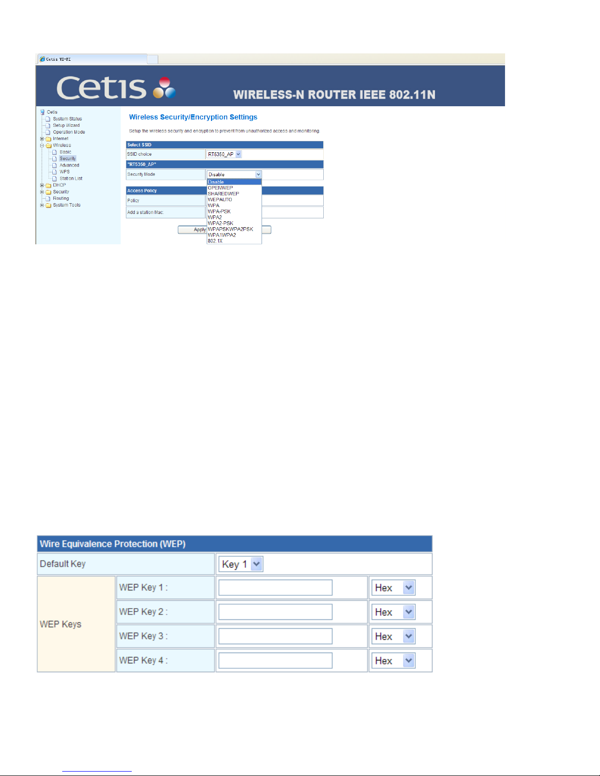
3.2 Security Setup
Set wireless security and encryption to prevent unauthorized access and monitoring.
Encryption approach: Select the required encryption approach from the pull-down list. If selected,
more parameters will be visible to be further set. If Disable is selected, this means no encryption is
chosen.
20 www.teledex.com M SERIES ANALOG CORDED USER GUIDE
Page 21
After the setting is finished, click Apply button to confirm it.
The wireless security settings prevent others from connecting to your wireless network and occupying
your network resource without your permission. It can help avoid hackers’ wiretapping and other
undesirable cyber-assaults.
If the gateway has wireless security settings, all the base units within the wireless network shall be set
according to the security setting there; for example, the password settings shall be identical, otherwise
it will fail to connect to the gateway via the radio.
Select the Service Set Identifier (SSID): The network name can select multiple SSIDs.
Safe mode: Corresponds with the encryption approach of network name.
There are multiple wireless security types for your selection. Under the security types, the security
setting options are different. Three common safe modes will be detailed below.
3.2.1 WEP
WEP is the abbreviation of Wired Equivalent Privacy which is a basic encryption approach. When WEP is
selected, the gateway will use the basic 802.11 WEP safe mode. It shall be noted here that 802.11N does
not support the WEP encryption approach. If you select the WEP encryption approach, the router might
operate in the low transmission rate. See the below figure for the specific setting options.
WEP safe mode includes OPENWEP, SHAREDWEP, and WEPAUTO.
M SERIES ANALOG CORDED USER GUIDE www.teledex.com 21
Page 22
WEPAUTO: If selected, the gateway will automatically select the open system or shared key mode
according to the request of base unit.
OPENWEP: If selected, the gateway will use the open system mode. At that time, the base unit within
the wireless network can link the wireless network through authentication without providing the
authentication password. But if required to transmit the data, the correct password must be provided.
SHAREDWEP: If selected, the gateway will use the shared key mode. At that time, the base unit within
the wireless network must provide the correct password for authentication, otherwise it cannot link the
wireless network and furthermore it cannot transmit the data.
The WEP key format includes the hexadecimal (Hex) and ASCII code. If the hexadecimal is used, the key
characters shall only be any of 0–9, A, B, C, D, E and F. If ASCII code is used, the key characters could
be any character on the keypad.
The Default Key, WEP Key, Key Type: They are used to select the key, set the specific key value, and
select the key type. The length of key is affected by the key type: the hexadecimal key needs to input 10
or 26 characters, while the ASCII key needs to input 5 or 13 characters. For 4 keys in the key selection,
it is allowed to use one of them or use several keys at the same time. In any case, the setting of the key
on the client network card must correspond with it.
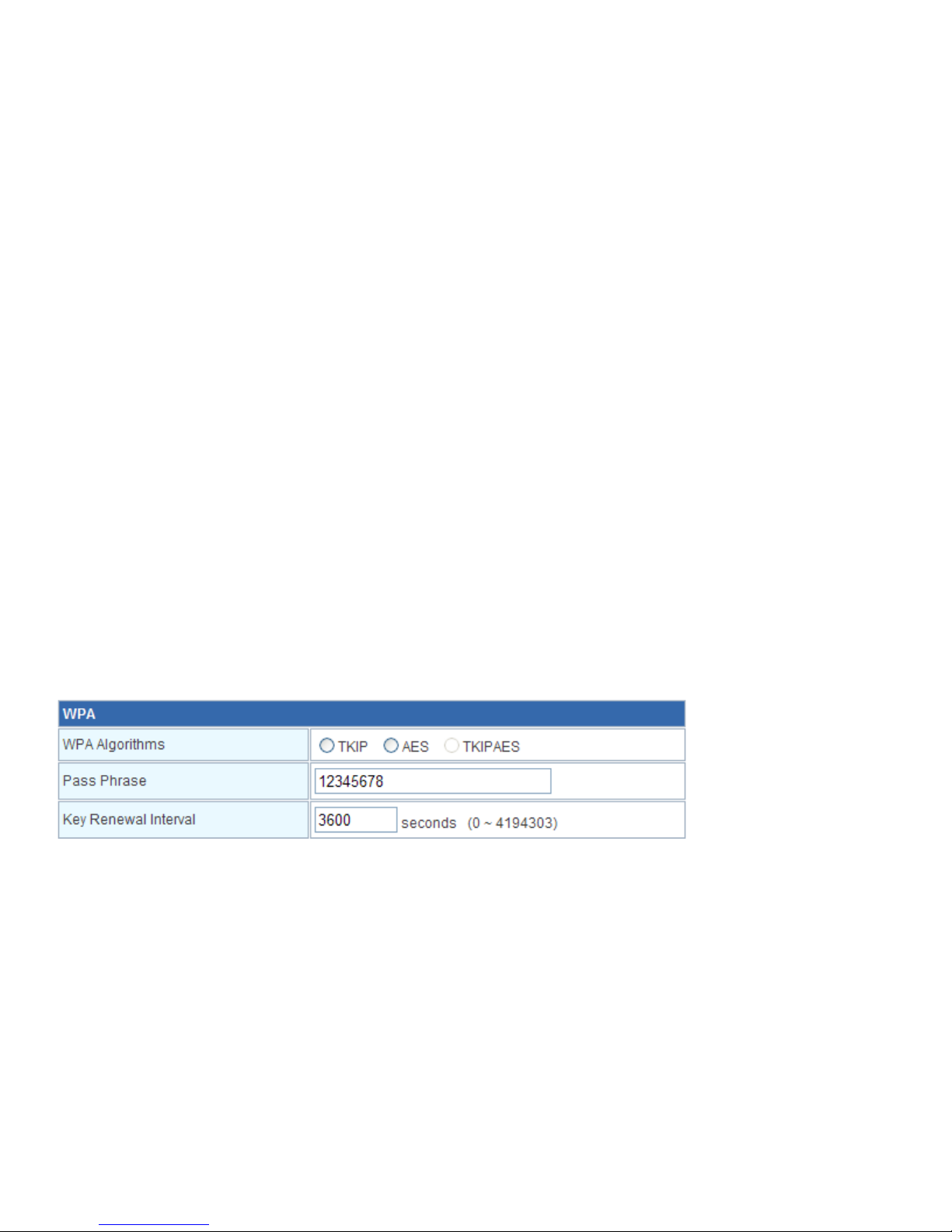
3.2.2 WPAPSK/WPA2PSKWIFI PROTECTED ACCESS
The WPA-PSK/WPA2-PSK security type is a simplified version of WPA/WPA2. It is the Wi-Fi Protected
Access mode based on a shared key. WPA and WPA2 were designed to replace WEP. With a high security
and simple setting, it is suitable for the common household users and small-sized enterprises. See the
below figure for the specific setting options. PSK = Pre-shared key mode (PSK, also known as Personal
mode) is designed for home and small office networks that don’t require the complexity of an 802.1X
authentication server.
WPA-PSK/WPA2-PSK safe mode includes WPA-PSK, WPA2-PSK, and WPA-PSK/WPA2-PSK.
WPA-PSK/WPA2-PSK: If selected, the gateway will automatically select the WPA-PSK or WPA2-PSK
safe mode according to the request of base unit.
WPA-PSK: If selected, the gateway will use the WPA-PSK safe mode.
WPA2-PSK: If selected, the gateway will use the WPA2-PSK safe mode.
WPA algorithm: The item is used to select the safe algorithm for encrypting the wireless data, the
options are TKIP (Temporal Key Integrity Protocol), AES, and TKIP/AES. The 802.11N mode does not
support TKIP algorithm, so the gateway might operate in a low transmission rate. It’s recommended to
use AES encryption.
22 www.teledex.com M SERIES ANALOG CORDED USER GUIDE
Page 23
Popular password: The item is the initial setting key for WPA-PSK/WPA2-PSK. It’s required to be 8–63
ASCII characters or 8–64 hexadecimal characters.
The Private Key Renewal Interval: The item is used to set the renewal period of broadcast and multicast
key. The unit is second and the minimum is 30. If the value is zero, it means no renewal.
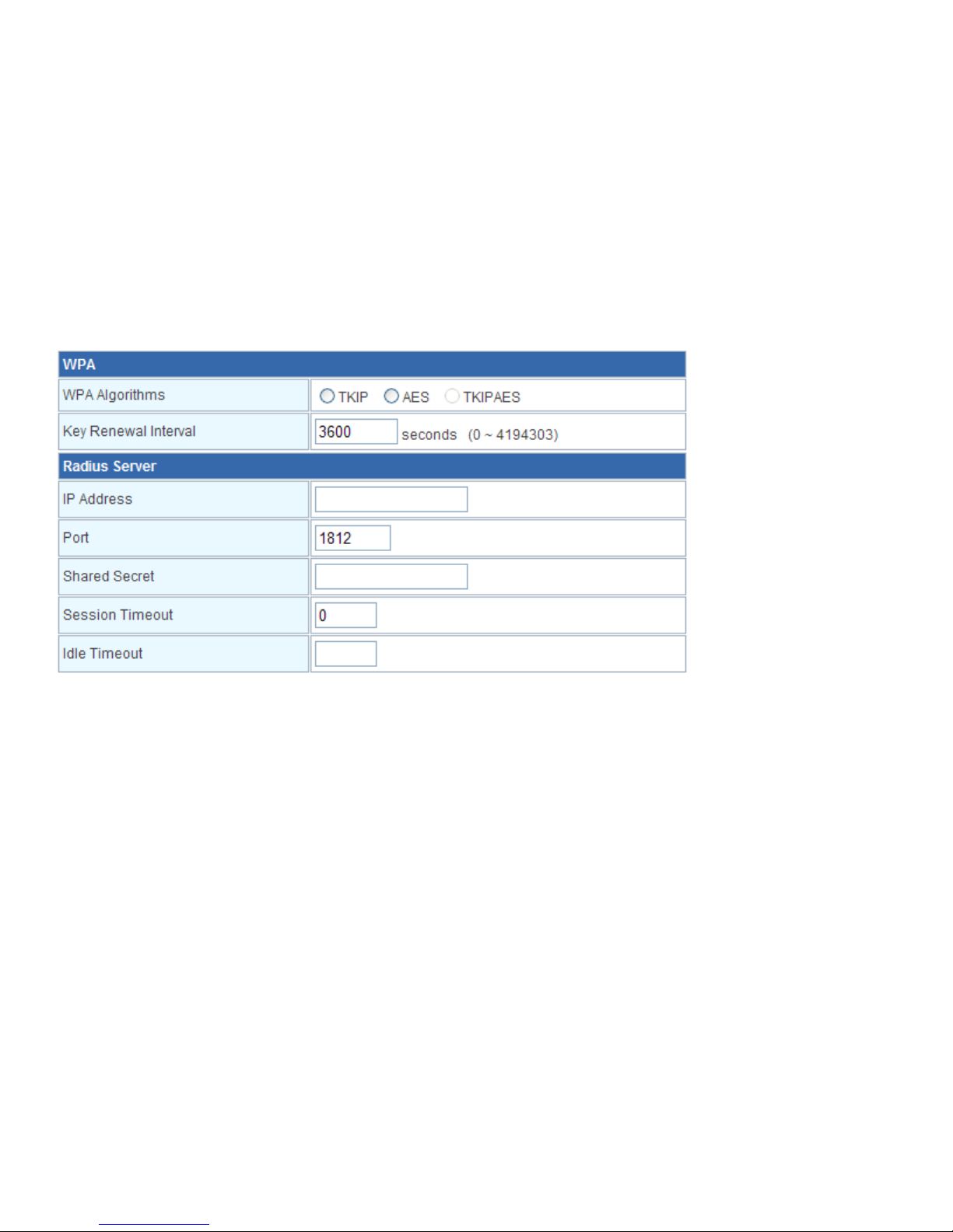
3.2.3 WPA/WPA2
The WPA/WPA2 is a stronger encryption algorithm than WEP. When the security type is selected, the
gateway will use a Radius server for ID authentication and to obtain the WPA or WPA2 safe mode of
key. It’s expensive to install a dedicated authentication server and the maintenance is rather complex,
therefore we do not recommend to use the security type for common users. See the below figure for
the specific setting options.
WPA/WPA2 safe mode includes WPA, WPA2, and WPA/WPA2.
WPA/WPA2: If selected, the router will automatically select WPA or WPA2 safe mode according to the
request of base unit.
WPA: If selected, the router will use WPA safe mode.
WPA2: If selected, the router will use WPA2 safe mode.
WPA algorithm: The item is used to select the safe algorithm for encrypting the wireless data, the
options are TKIP, AES, and TKIP/AES. The 802.11N mode does not support TKIP algorithm, so the
gateway might operate in a low transmission rate. It’s recommended to use AES encryption.
The Private Key Renewal Interval: The item is used to set the renewal period of broadcast and multicast
key. The unit is second and the minimum is 30. If the value is zero, it means no renewal.
IP address of Radius server: The Radius server is used to authenticate the identification of base unit
within the wireless network. The item is used to set IP address of Radius server.
Radius port: The Radius server is used to authenticate the identification of base unit within the wireless
network. The item is used to set Port # for Radius authentication service.
Radius shared key: The item is used to set the password for access to Radius service.
M SERIES ANALOG CORDED USER GUIDE www.teledex.com 23
Page 24
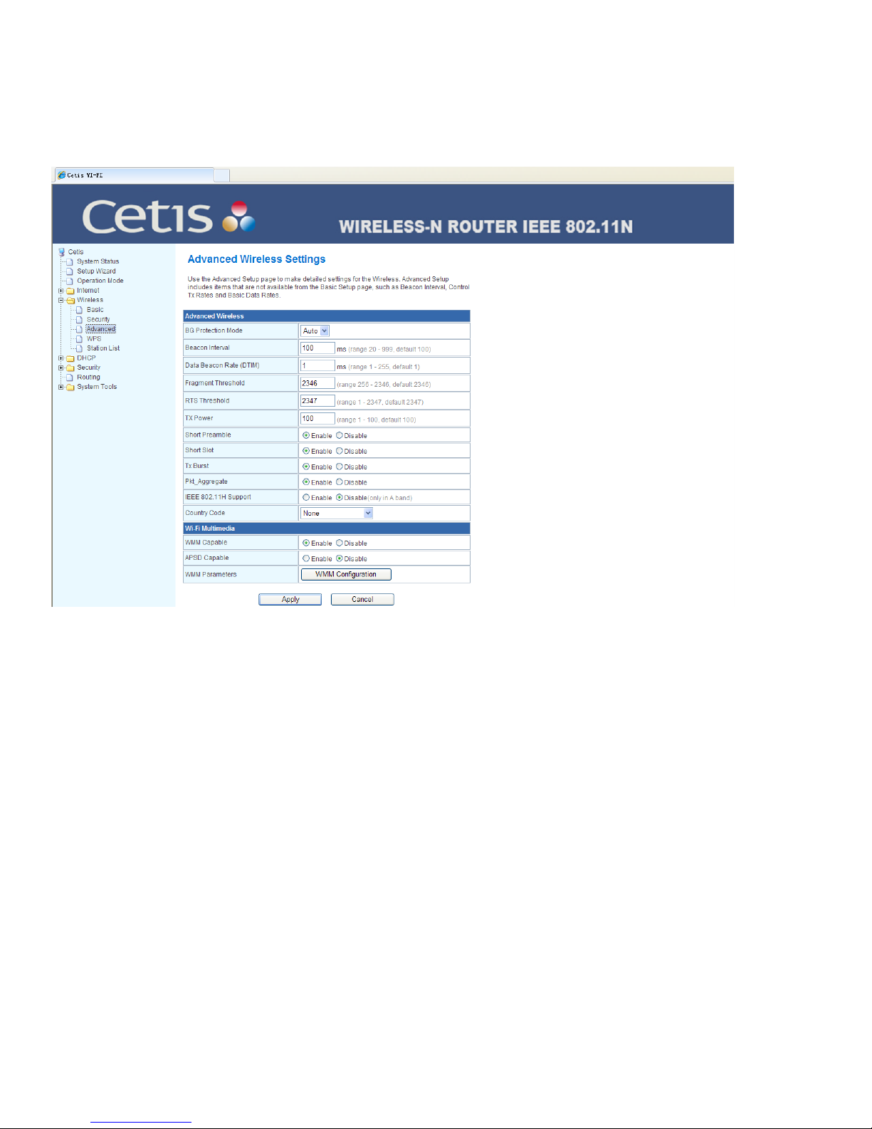
3.3 Advanced Settings
Advanced Settings are used to set the advanced wireless functions of the router. It’s advisable that
these operations be performed by a professional, because incorrect settings might reduce the wireless
functions of the router.
BG protection mode: It is favorable for the slow wireless link to successfully connect the gateway under
multiple complex modes. It is Auto by default.
Beacon interval: The gateway sends the Beacon broadcast signal for the synchronization of wireless
network. It represents the frequency of sending the Beacon broadcast signal. The default is 100 ms in
the scope of 20–999 ms.
Data beacon ratio (traffic indication message): The value is between 1 and 255, which specifies the
interval of delivery traffic indication message (DTIM). The DTIM is a countdown job telling the next client
window to receive the broadcast and multicast. When the gateway has stored the broadcast and multicast
message for relevant clients, it will carry the message of next DTIM interval in Beacon. When the client
hears the Beacon signal, he will receive the broadcast and multicast message. The default is1.
Dividing the boundary: Specify the fragment threshold for a data packet. When the length of a data
packet exceeds the fragment threshold, it will be automatically divided into several data packets. The
excessive data packets will result in the reduction of network performance. Therefore, the fragment
threshold shall not be set too low. The default is 2346.
Transmission request limit: Specify the RTS (Request to Send) threshold for a data packet. When
the length of a data packet exceeds the RTS threshold, the gateway will send RTS to the destination
24 www.teledex.com M SERIES ANALOG CORDED USER GUIDE
Page 25
website for negotiation. After receiving an RTS frame, the wireless website will return a CTS (Clear to
Send) frame to the gateway as the response, this represents that both of them can make the wireless
communication.
Transmission power: Used to set the wireless transmission power level. The default is 100 in the scope
of 1–100.
Wi-Fi multimedia capability: After WMM is enabled, it has wireless QOS (Quality of Service) functions
which can treat the audio and video data at priority to ensure the preferential delivery of audio and video
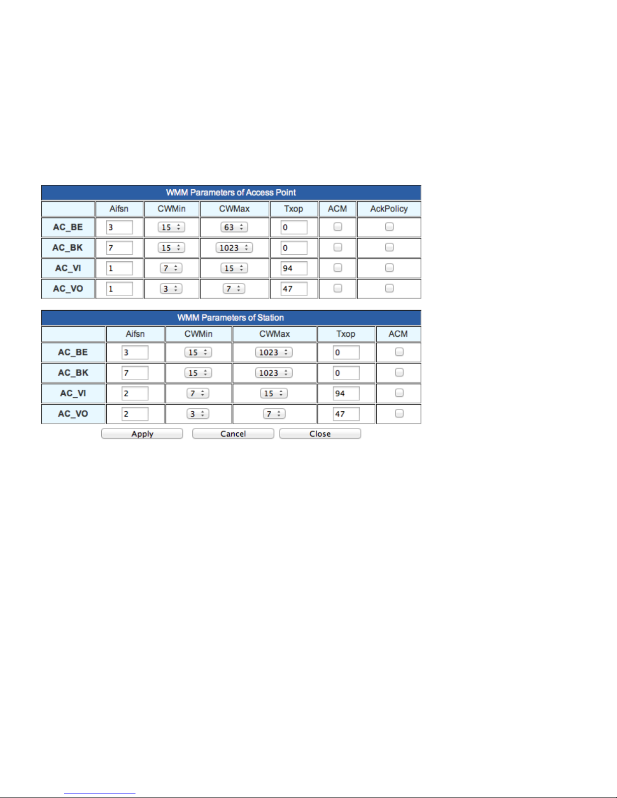
data. The option is enabled by default. WMM Confguration page below.
WMM (Wireless Multi Media) Parameters are governed by values as defined by EDCA (Enhanced Data
Channel Access). With EDCA, high-priority traffic has a higher chance of being sent than low-priority
traffic: a station with high priority traffic waits a little less before it sends its packet, on average, than a
station with low priority traffic.
AC = Access Category
AC_BE = Access Category_Best Effort
AC_BK = Access Category_Background
AC_VI = Access Category_Video
AC_VO = Access Category_Voice
CWMin = Contention Window Minimum
CWMax = Contention Window Maximum
AIFSn = Arbitration inter-frame spacing (AIFS), in wireless LAN communications, is a method of
prioritizing one Access Category (AC) over the other, such as giving voice or video priority over email.
M SERIES ANALOG CORDED USER GUIDE www.teledex.com 25
Page 26
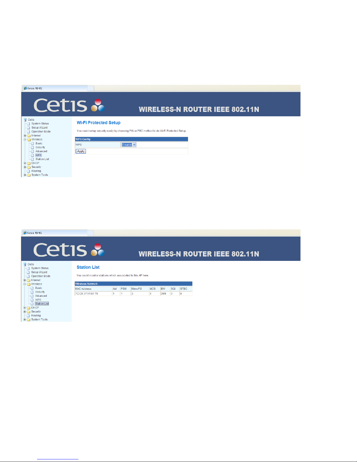
3.4 WPS
The WPS (Wi-Fi Protected Setup) simplifies setup and encryption, etc., of wireless networks. The WPS
can help the users at client automatically configure the network name (SSID) and wireless encryption
key to realize one-touch encryption.
It can be employed only when the client of user supports the WPS registration function.
3.5 Station List
Displays the basic information of all base units connecting the wireless network (the parameters of
MAC address and link rate etc.).
4 DHCP Server
4.1 DHCP Service
Here select enable or disable of the DHCP server. Set the scope of DHCP IP address, subnet mask, DNS
server, gateway, and release time.
26 www.teledex.com M SERIES ANALOG CORDED USER GUIDE
Page 27
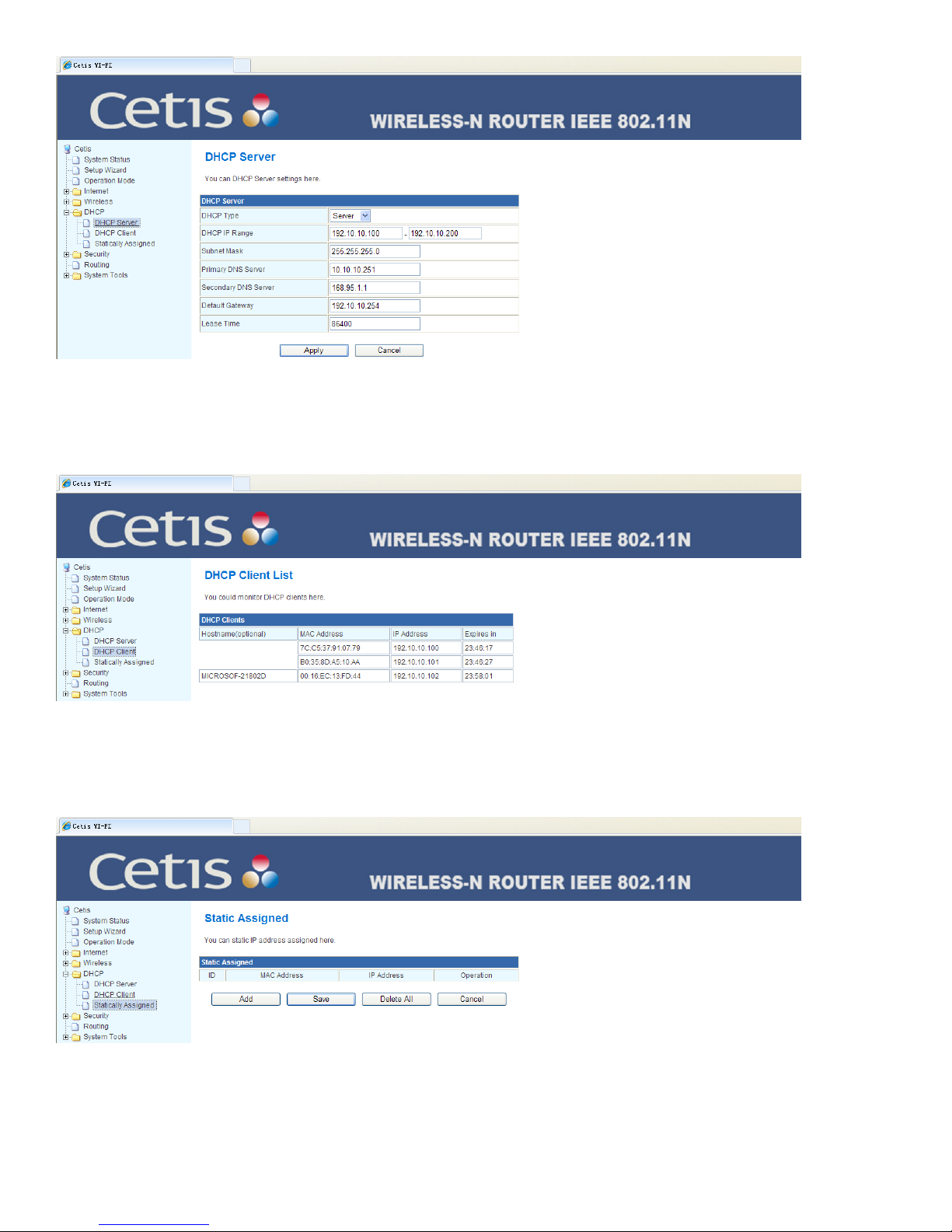
4.2 Client List
You can check the MAC address and IP address of equipment terminal connected through DHCP service.
4.3 Static Address Assignment
Here can assign a fixed IP address to the MAC address.
M SERIES ANALOG CORDED USER GUIDE www.teledex.com 27
Page 28

5 Security Setting
5.1 MAC/IP/Port Filtering
Respectively set the relevant MAC address, IP address, and the filtering option of port.
6 Routing Function
Manually add the static routing table information, check the current routing table information, enable
or disable RIP function.
28 www.teledex.com M SERIES ANALOG CORDED USER GUIDE
Page 29

7 System Tools
7.1 Change Login Password
You can set the account and password of administrator here.
M SERIES ANALOG CORDED USER GUIDE www.teledex.com 29
Page 30

7.2 Language Setting
You can reset the interface language display: simplified Chinese or English.
7.3 Time Setting
You can reset NTP (Network Time Protocol) server to configure the system time.
30 www.teledex.com M SERIES ANALOG CORDED USER GUIDE
Page 31

7.4 Upgrade Firmware
Update the firmware of gateway device to obtain the new function, including the update of webpage and
USB.
7.5 Recover Factory Default Settings
You can restore the factory default settings and restart the system. There is also a reset button at the
rear of the phone that can be accessed via a small tool such as a paperclip.
M SERIES ANALOG CORDED USER GUIDE www.teledex.com 31
Page 32
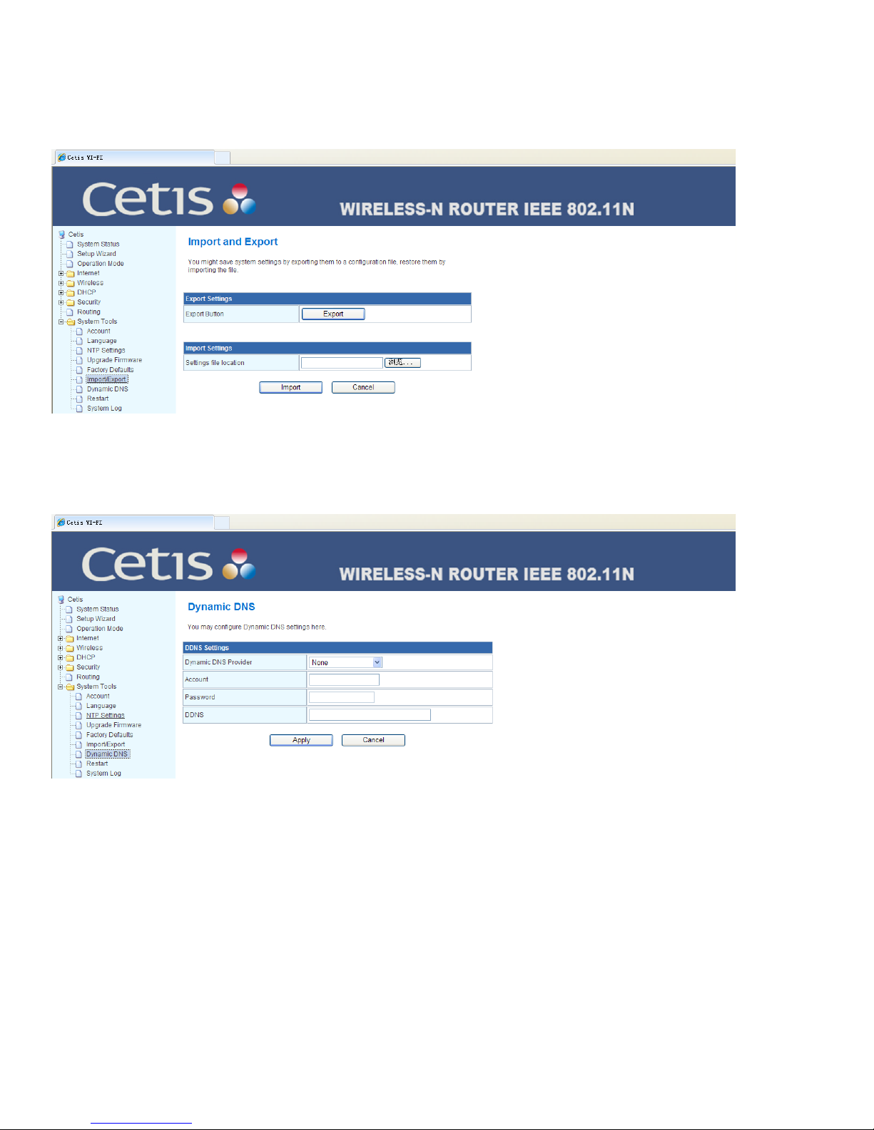
7.6 Back-up and Load the Configuration
You can save the system setting by exporting a configuration file and you also can import the exported
file into the system.
7.7 Dynamic DNS
You can configure the dynamic DNS (Domain Name Service) here.
32 www.teledex.com M SERIES ANALOG CORDED USER GUIDE
Page 33
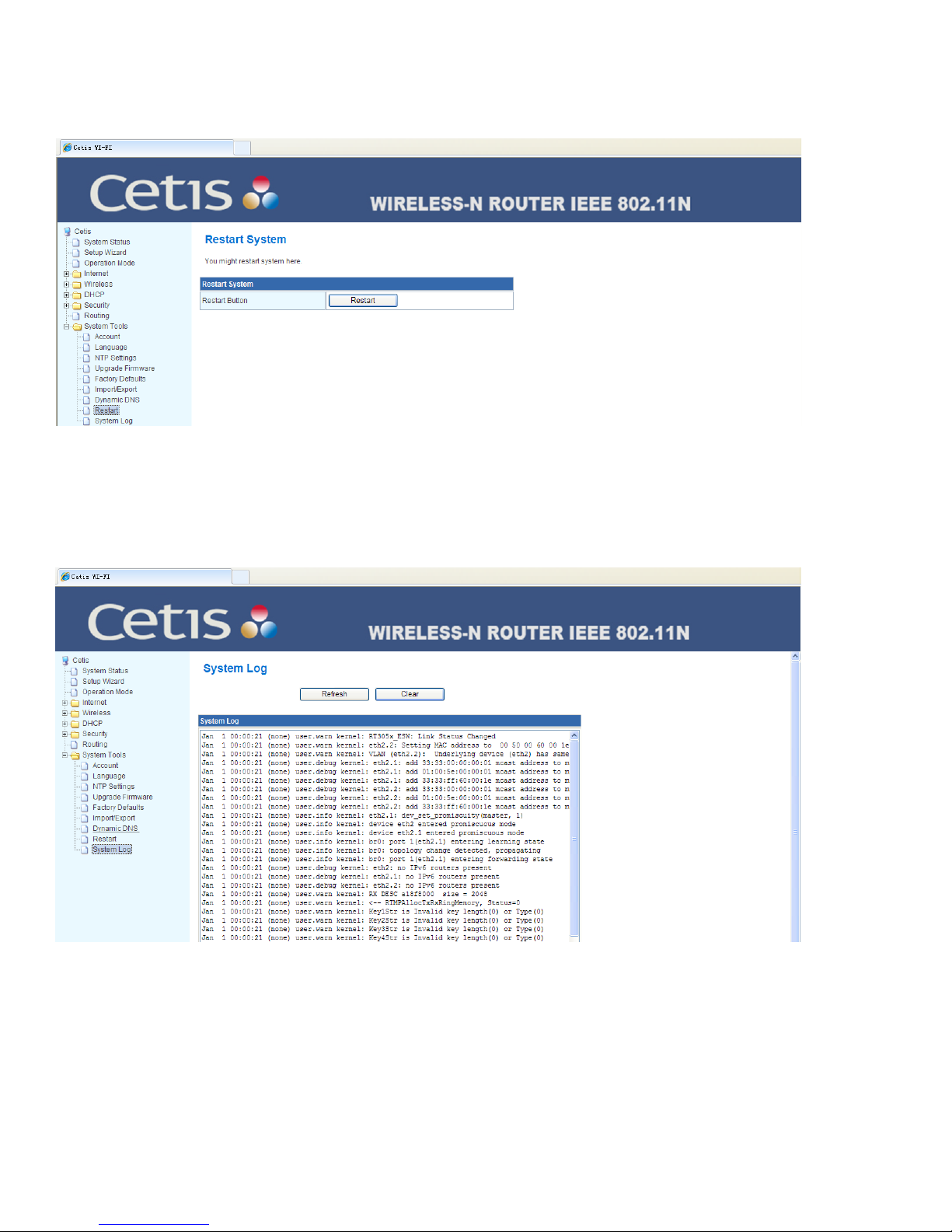
7.8 Restart the System
You can restart the system here.
7.9 System Log
It records the relevant operation and error warning, etc., by which you can check the system events that
occurred on the terminal.
M SERIES ANALOG CORDED USER GUIDE www.teledex.com 33
Page 34

Section D
Guest Card Samples
DEVICE CONNECTION
1. To connect your device, press and hold the BT key for 3 seconds, the
Bluetooth LED will blink and the speaker will generate a “toot” prompt
tone, on your personal device in Bluetooth settings, you will now see the
hotel phone. Select it to get connected and place calls through your cell
phone plan and listen to music.
2. Only one mobile device can be connected at a time
CALL PLACEMENT
1. Press the Bluetooth key on the hotel phone while your personal mobile
phone is paired to it. You will hear a dial tone through the hotel phone’s
speaker. You may now dial through the hotel phone OR your cell phone to
place a call using the superior speakers or handset of the hotel phone.
PLAY BLUETOOTH AUDIO
Use your mobile phone’s music player as the source.
1. Press uto start/stop the play.
2. Press to increase the sound volume.
3. Press to decrease the sound volume.
4. Press to select the previous music, press to select the next music.
Note: During the play, the Bluetooth LED automatically blinks.
34 www.teledex.com M SERIES ANALOG CORDED USER GUIDE
Page 35

DEVICE CONNECTION
1. To connect your device, press and hold the BT key for 3 seconds, the Bluetooth LED
will blink and the speaker will generate a “toot” prompt tone, on your personal device
in Bluetooth settings, you will now see the hotel phone. Select it to get connected and
place calls through your cell phone plan and listen to music.
2. Only one mobile device can be connected at a time
CALL PLACEMENT
1. Press the Bluetooth key on the hotel phone while your personal mobile phone is
paired to it. You will hear a dial tone through the hotel phone’s speaker. You may now
dial through the hotel phone OR your cell phone to place a call using the superior
speakers or handset of the hotel phone.
PLAY BLUETOOTH AUDIO
Use your mobile phone’s music player as the source.
1. Press uto start/stop the play.
2. Press to increase the sound volume.
3. Press to decrease the sound volume.
4. Press to select the previous music, press to select the next music.
Note: During the play, the Bluetooth LED automatically blinks.
M SERIES ANALOG CORDED USER GUIDE www.teledex.com 35
Page 36

Toll Free: +1.800.462.9446
Tel: +1.719.638.8821
Email: infoteledex.com
www.teledex.com
© 2014 Cetis, Inc. Product specifications and descriptions in this document subject to change without notice. CetisTM, Teledex®, TeleMatrix®, Scitec®, ExpressNet®, and
Teledex iPhoneTM are trademarks or registered trademarks of Cetis, Inc. TDX-M-ACorded-UG-052014
 Loading...