


ONEMINI Fire Alarm Panel
User and Installation Manual


Information ownership
© COPYRIGHT 2017, Teledata s.r.l.
All rights reserved.
Any full or partial distribution, modification or reproduction of this document are prohibited
without written authorization by Teledata s.r.l. except the following actions:
Fully or partially printing the document in its original format.
Transferring the document on web sites or other electronic systems.
Copying content without editing it and quoting Teledata s.r.l. as the owner of the
copyright.
NOTE: the content of this document cannot thus, be used to develop other content for your
retail purposes without a written authorization by Teledata s.r.l.
Requests for additional copies of this product or pertinent technical information should be
addressed to:
Teledata s.r.l.
20132 Milan - Italy - Via G.M. Giulietti, 8
Tel.: +39 02 27 201 352 / +39 02 25 92 795
Fax: +39 02 25 93 704
E-mail: info@teledata-i.com
Declaration of conformity
This equipment was designed according to the quality, reliability and performance criteria
adopted by Teledata.
Equipment must be professionally installed according to current regulations.
The equipment meets the following directives and standards:
EMC Directive (EMC) 2004/108/EC
Low Voltage Directive (LVD) 2006/95/EC
EN 54-2
EN 54-4 (A2:2006)


ONEMINI
FIRE ALARM CONTROL PANEL
USER AND INSTALLATION MANUAL - REV. 1.0.3 / 2018
PAGE 3
INDEX
1. Introduction to this manual 7
1.1 Obligations to this manual 7
1.2 Manual data 7
1.3 Warnings for manual addressees 7
2. Safeties and warranties 8
2.1 Safety rules 8
2.2 Intended use 8
2.3 Warranty restrictions 8
2.4 Technical support 8
3. Product identification 9
3.1 Manufacturer's identification data 9
3.2 Packaging content 9
3.3 Identify the model and the serial number 9
3.4 Standards compliance 10
4. Equipment management 11
4.1 Transportation 11
4.2 Environmental conditions 11
4.3 Unpacking 11
4.4 Replacement 11
4.5 Disposal 11
5. Introduction to ONEMINI 12
5.1 General features 12
5.2 Installation precautions 12
5.3 Technical specifications 13
5.3.1 HARDWARE features 13
5.3.2 Software features 13
5.4 Technical data 14
5.4.1 Datum plate 14
5.4.2 Electrical features 14
5.4.3 Functional features 14
5.4.4 Mechanical features 14
5.4.5 Environmental features 14

ONEMINI
FIRE ALARM CONTROL PANEL
USER AND INSTALLATION MANUAL - REV. 1.0.3 / 2018
PAGE 4
6. Hardware Configuration 15
6.1 Control Panel Equipment 15
7. Layout and connections 16
7.1 Logic board (TD595) layout 16
7.2 PT-LAN Card (optional) 18
7.3 ONERING Card (optional) 20
7.4 Power supplies and batteries 23
7.5 System description 24
7.5.1 Relations between the elements of the plant 24
7.5.2 Sounder and load connection 24
7.6 Communication with detectors and modules 25
7.6.1 Open loop configuration 25
7.6.2 Generic loop connection requirements 26
7.6.3 Open loop configuration ("T" junctions) 26
7.6.4 Open loop connection with "T" junctions connection requirements 26
7.6.5 Closed loop configuration 27
7.6.6 Connection requirements for a closed loop connection 27
7.6.7 Connectable loop devices 27
7.7 Connection to host computer 30
7.7.1 Point to Point connection 30
7.7.2 LAN or WAN connection 31
7.7.3 ONEMINI control panel ring network 32
7.8 Power supply 33
7.8.1 Network input features 33
7.8.2 Grounding features 33
7.8.3 Panel power supply features 33
7.9 Panel internal cabling 34
8. Control panel 36
8.1 Status led 36
8.2 Graphic interface 37
8.3 Types of users 37
8.4 Access levels 38
9. Basic operations for any operator 39
9.1 View basic information 39
9.1.1 Viewing events 40
9.1.2 Viewing assistance information 43

ONEMINI
FIRE ALARM CONTROL PANEL
USER AND INSTALLATION MANUAL - REV. 1.0.3 / 2018
PAGE 5
9.2 Login 44
10. Configuration 47
10.1 Setting up the panel 47
10.1.2 Run auto-addressing 48
10.1.3 Run self-programming 48
10.2 Detectors configuration 49
10.3 Modules configuration 52
10.4 Zones configuration 55
10.4.2 Link an event to a zoneSettings 55
10.4.3 Linking loops to zones 55
10.4.4 Linking devices to zones 56
10.4.5 Set zone operating parameters 57
10.4.6 Link an output module to a zone 58
10.5 Output zones configuration 59
10.6 Logic functions configuration 60
10.7 Setting system parameters 64
10.7.1 Setting the language 64
10.7.2 Entering panel information 64
10.7.3 Setting led and buzzer behavior 65
10.7.4 Setting remote communications 66
10.7.5 Setting loop features 67
10.7.6 Restoring factory settings 67
10.7.7 Setting peripheral features 67
10.7.8 Exporting data 67
10.7.9 Import data 68
10.7.10 Various system settings 69
10.8 Setting the calendar. 71
10.8.1 Setting the date and time 71
10.8.2 Setting daylight savings time 71
10.8.3 Setting holidays 73
10.8.4 Setting time intervals 73
10.8.5 Setting weekly trends 74
11. Use 75
11.1 Viewing events 75
11.1.1 Exporting data 75
11.2 Enabling users and changing login codes 76
11.2.1 Programmer 76
11.3 Managing alarms 76
11.3.1 Mute alarms and the unit 77

ONEMINI
FIRE ALARM CONTROL PANEL
USER AND INSTALLATION MANUAL - REV. 1.0.3 / 2018
PAGE 6
11.3.2 Reset alarms and the unit 77
11.3.3 Evacuation 77
11.4 Checking device status 78
11.4.1 Check loop status 78
11.4.2 Resetting a loop 78
11.4.3 Run device diagnostics 78
11.4.4 Diagnostics export. 79
11.5 Testing devices 79
11.5.1 Running a Walk Test 79
11.5.2 Testing the connection with modules and sensors 80
11.5.3 Identifying conflicts 80
11.5.4 Identifying mismatches 81
11.5.5 Testing led operations 81
11.6 Disable system elements 82
11.6.1 Disabling/Enabling a device 82
11.6.2 Disabling/Enabling a loop 83
11.6.3 Disabling/Enabling a zone 83
11.6.4 Disabling/Enabling an output 84
11.6.5 Disabling/Enabling a board 84
11.7 Modify a user password 84

ONEMINI
FIRE ALARM CONTROL PANEL
USER AND INSTALLATION MANUAL - REV. 1.0.3 / 2018
PAGE 7
1. Introduction to this manual
1.1 Obligations to this manual
Warning: this manual is an integral part of the equipment and must be kept for its
entire working life. The manual must be enclosed with the equipment in the event
of transfer to third parties.
The manual must be consulted for all those situations tied to the equipment's
working life from its receipt until its disposal.
It must be kept in a clean place accessible to operators, and kept in good
conditions.
1.2 Manual data
Equipment: ONEMINI
Title: User and Installation Manual
Code or edition: v. 1.0.2 ENG
Print month and year: March 2018
Manual type: original instructions
1.3 Warnings for manual addressees
Graphic concepts adopted in the text are illustrated below.
Warning: operations to be carefully performed or important information.
Note: important information, highlighted after the text they refer to.
Suggestions: practical information for good function operations.

ONEMINI
FIRE ALARM CONTROL PANEL
USER AND INSTALLATION MANUAL - REV. 1.0.3 / 2018
PAGE 8
2. Safeties and warranties
2.1 Safety rules
The information in this manual section aim to ensure that the device is correctly installed and
handled. It is assumed that anyone who has to do with the device is familiar with the content
of this chapter.
2.2 Intended use
The equipment must only be installed and used as described in this manual and for the
purposes described in the advertising material distributed by Teledata S.r.l. It can only be
connected to equipment, components and devices manufactured by third parties as
recommended and permitted in this manual or by Teledata S.r.l. directly.
The equipment was designed, manufactured and tested to meet the stated safety standards.
If, during the design of the systems in which it is installed, installation and use the instructions
in this manual are followed, the equipment is not harmful to people or property.
2.3 Warranty restrictions
Teledata is not liable for direct or indirect damages to people or property due to equipment
use in conditions other than those intended.
Qualified personnel must install this equipment strictly following the instructions in this
manual and according to local laws, standards and safety regulations in effect.
This product is guaranteed against material and factory defects for 12 months from
inspection date. The warranty does not cover defects due to:
Improper use and neglect.
Damages due to exposure to the elements.
Vandalism.
Material wear.
The warranty is invalid when faults are due to improper use or operating procedures not
contemplated in this user manual.
2.4 Technical support
This manual was drafted with care and is intended for qualified personnel. For any questions
or special technical requests, please contact our personnel. Please write or call to contact
personnel able to answer your questions and provide assistance.
Service email: info@teledata-i.com
Service phone number: +39 0227201352
Service fax number: +39 022593704

ONEMINI
FIRE ALARM CONTROL PANEL
USER AND INSTALLATION MANUAL - REV. 1.0.3 / 2018
PAGE 9
3. Product identification
3.1 Manufacturer's identification data
Teledata s.r.l.
Head office 20132 Milan - Italy - Via G.M. Giulietti, 8
Operating center 20063 Cernusco Sul Naviglio - Italy - Via Brescia, 24
Tel.: +39 02 27 201 352 / +39 02 25 92 795
Fax: +39 02 25 93 704
E-mail: info@teledata-i.com
3.2 Packaging content
The packaging contains the following items:
Description
Quantity
ONEMINI panel
1
Resistances, diodes and jumpers kit
1
Installation and user manual (this manual)
1
3.3 Identify the model and the serial number
Inside and out the box of the panel there are identification stickers that must not be removed
under any circumstance. Please see plate information for service calls, maintenance or
accessories.

ONEMINI
FIRE ALARM CONTROL PANEL
USER AND INSTALLATION MANUAL - REV. 1.0.3 / 2018
PAGE 10
3.4 Standards compliance
EN 54-2: Fire detection and fire alarm systems - Control and indicating equipment.
EN 54-4: Fire detection and fire alarm systems - Power supply equipment (integrated
in the control panel).
Product type: Fire detection and fire alarm systems for buildings.
Intended use: Fire safety.
Essential characteristic
Harmonized tech. spec.
EN54/2:1997/A1:2006:AC1999
EN54/4:1997/A2:2006/AC:1999
Performance under fire
condition
cl. 4, 5, 7
-
Response delay
(response time to fire)
cl. 7.1, 7.7
Operational reliability
cl. 4, 5, 6, 7, 8, 9, 10, 12, 13, 14
cl. 4, 5, 6, 7, 8
Durability of reliability:
Temperature resistance
cl. 15.4
cl. 9.5
Durability of reliability:
Vibration resistance
cl. 15.6, 15.7, 15.15
cl. 9.7, 9.8, 9.15
Durability of reliability:
Electrical stability
cl. 15.8, 15.13
cl. 9.9
Durability of reliability:
Humidity resistance
cl. 15.5, 15.14
cl. 9.6, 9.14

ONEMINI
FIRE ALARM CONTROL PANEL
USER AND INSTALLATION MANUAL - REV. 1.0.3 / 2018
PAGE 11
4. Equipment management
4.1 Transportation
Once the equipment is carefully packaged and boxed, typical precautions must be taken
during transport meaning the box must be positioned and secured to avoid tipping or falling
that could damage equipment. Temperature limits must also be observed.
4.2 Environmental conditions
Observe temperature limits:
-40° / +70°C for storage and transport.
-5° / +40°C for operations.
4.3 Unpacking
Upon receiving the equipment, carefully unpack, being careful to dispose waste according to
current waste disposal regulations.
4.4 Replacement
To replace obsolete equipment, disconnect it and connect the new device according to the
relevant installation diagrams.
Dispose of the old equipment according to current waste disposal regulations.
4.5 Disposal
Avoid destruction by incineration and disposal in waterways. The product must be safely
disposed.
Before disposal, batteries must be removed from all products containing batteries being
careful to avoid short circuits. Observe current regulations for battery disposal.

ONEMINI
FIRE ALARM CONTROL PANEL
USER AND INSTALLATION MANUAL - REV. 1.0.3 / 2018
PAGE 12
5. Introduction to ONEMINI
5.1 General features
ONEMINI is a microprocessor-programmable fire detection control panel. This control panel
uses an analogue addressed system and an autonomous management of indications and
warning procedures.
The control panel is able to manage the fire detection through 1 analogue addressed lines.
The loop can control up to 240 detectors and IN/OUT modules.(120 devices for S Light
version)
The system is provided with a 32-bit microprocessor with RAM, flash memory and EEPROM
memory for the non-volatile storage of the configuration data.
The control panel can be programmed using the touch screen or by importing programming
data from a USB key.
Like all Teledata products, ONEMINI can be managed through the integrated supervisory
and control software.
5.2 Installation precautions
The electronic boards are provided with semiconductors that are sensitive to electrostatic
charges. For this reason the boards should be handled by their edges and their electronic
components should not be touched.
Carry out a good grounding in order to reduce the damageability and noise sensibility.
During the phase of designing the system, required autonomy should be taken into
consideration in order to scale the batteries to be utilized.
Disconnect the batteries, the AC power and any power supply before inserting or removing
an electronic board and before carrying out any maintenance work on the control panel
(except for the loading of a new FW version).
Peripheral devices like detectors, modules, sounders etc. that are not compatible with the
control panel can cause an improper operation of the control panel or even damage it.
It is therefore necessary to use materials compatible with the Teledata control panels.
ONEMINI control panel must be used with n°2 12V - 7.2Ah batteries

ONEMINI
FIRE ALARM CONTROL PANEL
USER AND INSTALLATION MANUAL - REV. 1.0.3 / 2018
PAGE 13
5.3 Technical specifications
5.3.1 HARDWARE features
32 bit microprocessor addressable control panel.
1 loop addressable with digital protocol, configurable as open or closed.
Graphic touch screen display (480x272 TFT 4.3”).
Loop short circuit protection.
14 front LEDs.
2 supervised output for siren or dialer (20,6 to 27,6Vdc @ 500mA).
1 alarm form C output (30Vdc @ 1A).
1 fault form C output (30Vdc @ 1A).
1 RS-485 line for peripherals.
1 RS-232 for supervisor data communication.
1 USB for data import export
Colored side led.
16 zone leds. (OPTIONAL board TD596A).
Battery capacity: 2x7.2Ah with EN54-4 charger management.
Supervised AUX power supply output 20,6 to 27,6Vdc @ 1A with shortcut protection.
Dimensions: 330x310x80 mm
Power Supply: 230V AC
5.3.2 Software features
Up to 240 addressable device ( 120 for S-Light version)
Splitting up to 192 detection zone.
192 logical functions.
Archival more than 850 events.
Analog loops auto programming.
Analog loops auto addressing.
Devices Mapping.
Connection with other control panels using a fault tolerant network.
Multiple language management.
Fully customizable with personal logo, color and multicolored side LEDs.
Management of different types of analog detectors and modules:
Thermal, optical and mixed detectors
Input Modules
Output Modules
Addressed call points
Addressable sirens
Wireless translator

ONEMINI
FIRE ALARM CONTROL PANEL
USER AND INSTALLATION MANUAL - REV. 1.0.3 / 2018
PAGE 14
5.4 Technical data
5.4.1 Datum plate
Primary voltage
230 Vac / 50 Hz
Primary consumption
200mA ~
230V~ fuse
F4Ah
5.4.2 Electrical features
Minimum operating voltage
21.6 V
Backup batteries
n° 2 (12Vdc/7.2Ah)
Maximum internal batt resistance
800mOhm
Available current for external loads
1A
Standby absorption
300 mA – 27,6V
Monitored sounder line
Max. 500mA – 20,6 to 27,6DC
Fault relay
Max. 1A - 30V DC/120V AC
5.4.3 Functional features
Operating keyboard
Touch screen
Optical messages
Led
Acoustic messages
Buzzer
Visualization of the events
480x272 TFT 4.3”
Serial output for PC
N° 1 – RS232
Event log
Max. 850
Working mode
Guarded/Unguarded
Programming/Management hardware key
Multilevel password
Number of analogue lines
1 loop
Exclusion of the analogue line
Single – multiple
I/O Modules / Detectors
Max. 240 ( max 120 for S-Light)
Programming type
Manual or by PC
Configuration of the analogue line
192 software zones
Analogue lines connection
Open or closed loop
Length of the detector lines
Max. 5000m
Type of cable
Shielded
5.4.4 Mechanical features
Protection level
IP30
Cabinet
Iron
Dimensions (WxLxD)
330 x 310 x 80 mm
Weight (without batteries)
6 Kg
Painting
Epoxy resin
Color
Black
Conduit holes
4 x 25 mm
5.4.5 Environmental features
Storage temperature
(-40 ÷ +70)°C
Operating temperature
(-5 ÷ +40)°C
Operating humidity (relative)
90%

ONEMINI
FIRE ALARM CONTROL PANEL
USER AND INSTALLATION MANUAL - REV. 1.0.3 / 2018
PAGE 15
6. Hardware Configuration
6.1 Control Panel Equipment
When fully equipped the control panel can include:
1 main logic board (TD595)
1 synoptic led (ONE16 TD596)
1 PT-LAN network card (for LAN or WAN network connection)
1 ONERING card (for panel network connection)
2 batteries (max 12V @ 7,2 Ah)

ONEMINI
FIRE ALARM CONTROL PANEL
USER AND INSTALLATION MANUAL - REV. 1.0.3 / 2018
PAGE 16
7. Layout and connections
7.1 Logic board (TD595) layout
J1
J9
J12
J6
Y3
J11
J7
Y4
Y2
JP3
J13
JP4
J4
J10

ONEMINI
FIRE ALARM CONTROL PANEL
USER AND INSTALLATION MANUAL - REV. 1.0.3 / 2018
PAGE 17
The following connectors are available:
Connector J7: ONERING card connections
Connector Y2: touch screen connection
Connector J11: PT-LAN card connections
Connector J13: Batteries connection
Connector J1: AL1 power supply and DIM power supply control
Connector J9: fire loop send and return
Connector J4: RS-485, AUX, fault output
Connector J10: form C alarm and form C fault
Connector J6: for RS-232 connection.
Connector JP3: for programming protection (closed=enabled)
Connector JP4: to set watchdog state.
Connector J12: supervised output for siren or dialer
Connector Y3: connector USB port
Connector Y4: Factory reset button
Y3 and J1 are connectors with predefined wiring and should be connected to
elements that are already installed in the control panel. These connectors
should be disconnected and reconnected only in case boards have to be
replaced or added.
The respective wiring of the connectors J9, J4, J10, J6, J11 and J7 depends on the
equipment configuration in which the control panel is connected.
Further on are described the connector functionalities.
Connector J13
PIN no.
NAME
FUNCTIONALITY
1
VBATT-
Batteries negative power supply
2
VBATT+
Batteries positive power supply
Warning: if a short circuit on battery is done when power supply is switched on, a quick reset shall happen on
control panel and a “system fault” event should appears.
Connector J1
PIN no.
NAME
FUNCTIONALITY
1
DIM-
DIM- control PS1 power supply
2
DIM+
DIM+ control PS1 power supply
3
GND
Negative alim
4
PS+
Positive alim
Connector J9
PIN no.
NAME
FUNCTIONALITY
1
RET-
Loop Return -
2
RET+
Loop Return+-
3
FW-
Loop Send-
4
FW+
Loop Send+
Connector J4 and J12
PIN no.
NAME
FUNCTIONALITY
1
485-
RS-485 line -
2
485+
RS-485 line +
3
GND
Ground
4
AUX+
AUX power output (27Vdc @ 500mA)
5
GND
Ground
ONEMINI
FIRE ALARM CONTROL PANEL
USER AND INSTALLATION MANUAL - REV. 1.0.3 / 2018
PAGE 18
PIN no.
NAME
FUNCTIONALITY
6
OUTMON1
Output monitored 1
7
GND
Ground
8
OUTMON2
Output monitored 2
Connector J10
PIN no.
NAME
FUNCTIONALITY
1
GND
2 RL1NO
3 RL1C
4 RL1NC
FAULT2
FAULT1
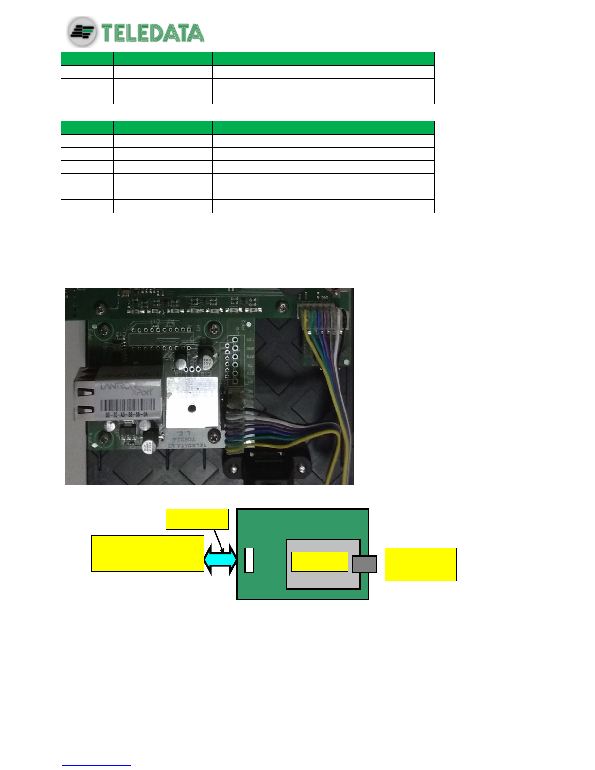
7.2 PT-LAN Card (optional)
The PT-LAN card, if included, is supplied with a flat cable and must be connected to the main
board on connection J3 as shown below:
Connect as shown:
Connect the flat cable to the connector J3 (7 pin) of the network card and to
connector J11 (6 pin) of the main board. Leave free the 7th pin on the panel side
which corresponds to the NC function.
Pin 1
Pin 7
To J11 connector of
the mother board
PT-LAN
RJ-45
connector
Flat cable

ONEMINI
FIRE ALARM CONTROL PANEL
USER AND INSTALLATION MANUAL - REV. 1.0.3 / 2018
PAGE 19
To avoid damaging, do not force connector insertion.
Connect the control panel to the network card on connector RJ-45 of the network card using:
10BASE-T crossed network cable: for connection to the host PC
10BASE-T direct network cable: for connection to a hub.

ONEMINI
FIRE ALARM CONTROL PANEL
USER AND INSTALLATION MANUAL - REV. 1.0.3 / 2018
PAGE 20
7.3 ONERING Card (optional)
The ONERING expansion card permits to connect up to 32 ONEMINI model panels. The
purpose is to share information between panels, allowing also to do cross outputs activations.
The ONERING card, is supplied with a flat cable and must be connected to the main board
on connection J7 as shown below:
The control panel should be connected with cables with the following technical specifications:
5 1
Conn. J6
Conn. J7
ONERING
Bus connections
Flat cable
To J7 TD571/A
Master card
TD571/A

ONEMINI
FIRE ALARM CONTROL PANEL
USER AND INSTALLATION MANUAL - REV. 1.0.3 / 2018
PAGE 21
Use CAN bus cable with granted impedance 120Ω. (es. Belden 9842)
Max distance at 50 kbit/s : 1000m
Network cable characteristics
LENGTH
TYPE OF CABLE
Up to 40mt
0.25-0.34mm2
Up to 300mt
0.34-0.6mm2
Up to 600mt
0.5-0.6mm2
Up to 1000mt
0.75-0.8mm2
With shielded and twisted 1mm2 fire cable, maximum distance at 50Kbit/s speed
is 400m.
ONERING expansion card installation is described below:
1. Turn off the panel, disconnecting the battery and removing the fuse.
2. Insert four 5mm M/F standoffs.
3. Assemble the ONERING card and fix it with four 3x6mm screws.
4. Connect the data flat cable in J7 connector of ONEMINI panel.
5. Connect the power cable to PSOUT+ and GND terminals of J4 connector of ONEMINI
panel.
6. Turn on the panel, connecting the battery and inserting the fuse.
J7 Connector on TD542/C ONERING card
N. PIN
NAME
FUNCTIONALITY
1
CH side a
Bus H side A
2
CL side a
Bus L side A
3
Gnd/bus
Gnd bus ref.
4
Gnd/bus
Gnd bus ref.
5
CL side b
Bus L side B
6
CH side b
Bus H side B
J2 Connector on TD542/C ONERING card
N. PIN
NAME
FUNCTIONALITY
5 1 GND +24Vdc
conn. J6 conn. J2 6
conn. J7
OLYNET card
1

ONEMINI
FIRE ALARM CONTROL PANEL
USER AND INSTALLATION MANUAL - REV. 1.0.3 / 2018
PAGE 22
1
24Vdc
+ Power supply
2
GND
- Power supply
ONERING cards must be connected between each other as described below:
CH A side of ONERING 1 to CH B side of ONERING 2
CH A side of ONERING 2 to CH B side of ONERING 3, and so on until the ring is
closed back to ONERING 1
CL A side of ONERING 1 to CL B side of ONERING 2;
CL A side of ONERING T 2 to CL B side of ONERING 3, and so on until the ring is
closed back to ONERING 1.
Connect also the ground bus (GND) between two consecutive ONERING cards
ONERING ring network is developed to ensure functionality also in case of a bus cut or short.
The system is able to keep the data transfer between the panels in degraded mode, in case
of power failure of one or more ONERING cards.
6
5
4
3
2
1
6
5
4
3
2
1
6
5
4
3
2
1
ONERING 2
OLYNET 3
ONERING 1
ONERING 3

ONEMINI
FIRE ALARM CONTROL PANEL
USER AND INSTALLATION MANUAL - REV. 1.0.3 / 2018
PAGE 23
Check the bus connections before starting the system.
7.4 Power supplies and batteries
Inside ONEMINI panel it is possible to two 7.2Ah batteries.
Batteries must be cabled in series and blocked with the nylon wire wraps supplied.

ONEMINI
FIRE ALARM CONTROL PANEL
USER AND INSTALLATION MANUAL - REV. 1.0.3 / 2018
PAGE 24
7.5 System description
Below is described a description of the control panel logic and of connections required to setup the system.
7.5.1 Relations between the elements of the plant
The following picture shows the relations between the various elements that make up the
plant managed by the control panel.
Devices (detectors, call points, etc.) are grouped in zones linked between them by specific
logical functions that can activate one or more outputs.
7.5.2 Sounder and load connection
The outputs 5, 6,7,8 of the connector J12 are used to connect the loads (sounders, bells,
optical acoustic displays) for which it is necessary to monitor the cut and the short.
The control panel is able to detect the presence of a cut or of a short circuit on the connection
line of the loads. In the event of one of these cases the control panel will indicate it by an
optical indication (message on the display, yellow LED for sounder fault is on) or acoustic
signal (buzzer).
Z1
Z2
Zn
Logic function: Z1 | Z2 ...
O1
O2
On

ONEMINI
FIRE ALARM CONTROL PANEL
USER AND INSTALLATION MANUAL - REV. 1.0.3 / 2018
PAGE 25
Follow the instructions below:
Connect a 3.3kΩ ¼ Watt end of line resistance and a 1N4007 diode. Normally these
resistors and diodes are provided with the control panel
Connect loads to the panel, use cables with a maximum resistance of 50 Ω.
The maximum current available is 1A @ 27Vdc.
The diagnostics of these outputs is activated only when the load is deactivated, that is when
the control panel does not report any alarm.
If load is used with internal protection diode, such as optical acoustic displays protected
against inversion, the protection diode may be omitted.
7.6 Communication with detectors and modules
The
ONEMINI control panel communicates with addressable detection and control devices
through a two-wire line, called loop.
It is possible to use the control panel in open loop systems or closed loop systems.
According to the effective standards, in systems where there are more than 32
modules/detectors, it is necessary to use the closed loop configuration.
7.6.1 Open loop configuration
Below an example of open loop configuration.
Dl
Pin 5/7
Pin 6/8
End of line
resistor
L1+ AND
ONEMINI
FIRE ALARM CONTROL PANEL
USER AND INSTALLATION MANUAL - REV. 1.0.3 / 2018
PAGE 26
This configuration uses lines L+ e L- on pins FW+ and FW-
It is possible to connect up to 32 detectors and I/O modules.
7.6.2 Generic loop connection requirements
Match the following requirements:
Twisted and shielded 2-conductor cable,
Loop with only detectors, call points and modules, total line length should not exceed:
LENGTH
TYPE OF CABLE
Up to 1250mt
2x0.5mm2
Up to 1850mt
2x0.75mm2
Up to 2500mt
2x1mm2
Up to 3500mt
2x1.5mm2
Up to 5000mt
2x2.5mm2
Line resistance should not exceed 100Ω,
Line cables installed on a dedicated path,
Cables placed at a proper distance from the power lines.
7.6.3 Open loop configuration ("T" junctions)
Below an example of open loop configuration with "T" junctions.
7.6.4 Open loop connection with "T" junctions connection
requirements
Match the following requirements:
The total length of all legs should not exceed the maximum allowed length, according
to the section of the cable used,
Total resistance from the control panel connectors to the end of every junction should
not exceed 100Ω.
Detector
Module
L1 – AND
L1 – AND

ONEMINI
FIRE ALARM CONTROL PANEL
USER AND INSTALLATION MANUAL - REV. 1.0.3 / 2018
PAGE 27
7.6.5 Closed loop configuration
Below an example of closed loop configuration.
This type of configuration uses L- and L+ FW and L- and L+ RET
It is possible to connect up to 240 detectors and I/O modules.
If SFx000E type sensors are used, install an insulator module or sensor/module
with on-board insulator for every 32 devices as required by current
specifications.
7.6.6 Connection requirements for a closed loop connection
Match the following requirements:
Total line length (between OUT and IN) should not exceed the maximum allowed
length according to the section of the cable used.
7.6.7 Connectable loop devices
It is possible to connect the following Argus’s devices on the loop:
BS5000 (40900) bases for SFx000 and SFx000E detector installation.
SF5100 (40910-8) optical smoke detector
SF5200 (40920-8) optical and rate of rise detector at 58 °C (class A1 and A1R)
SF5300 (40930-8) temperature detector, (class A1R and B)
SF5100E (IV100) (like SF5100 but without isolator)
SF5200E (IV200) (like SF5200 but without isolator)
SF5300E (LV350) (like SF5300 but without isolator)
Detector
Call point
L1+ AND
L1 – AND
L1 + RIT
L1 – RIT
Call point
Detector
Output
Module
Input
Module
Input
Module
Detector
Detector

ONEMINI
FIRE ALARM CONTROL PANEL
USER AND INSTALLATION MANUAL - REV. 1.0.3 / 2018
PAGE 28
FDVCP500 (40800) call point
FDMM10 (40100-m) supervised input module
FDMM01S (40010-m) supervised output module
FDMM02 (40002-m) form C output module
FDS500 (40300) addressable sounder
FDW2W transceiver for wireless devices
FDMM12 (40102-m) Input/Output module
FDMM11S (40110-m) supervised input/output module
FDXMM11S (40110) supervised input/output module
FDMC404 (40110) 4 input 4 output module
FDMC602 (40602) 6 input 2 output module
FDVCP500IP67 (40801) call point resettabile allarm
FDCWS100AV Electronic sounder with addressable flashing
FDVFI100 (40330) Addressable LED flashing
FDVMCZ500 (40500) Remote addressed indicator
FDVBLS100/32 32 tone sounder
SF100 Conventional optical detector
SF200 Conventional optical and thermal smoke detector
SF400 Conventional thermal smoke detector
BSE100 conventional base
BRL100 relè base
All the above mentioned devices can be addressed by means of the appropriate
programming tool FDVPU1000.
By means of the same tool it is also possible to read some basic parameters of the different
devices, and to program the type of functionality of the temperature detectors SF3500.
For more information about this tool, please refer to its dedicated manual.
Follow the instructions below:
All above mentioned devices are provided with an incorporated line insulator. This
element, inside the devices, is connected to the line. It is therefore necessary to strictly
observe the line wiring instructions (line-input, line-output) when any kind of device is
going to be connected to the loop, as described in the data sheet attached to the
device.
It is necessary to strictly observe the instructions concerning the input/output loads
connection described in the data sheet of all input/output devices (I/O modules)
It is also possible to manage, by using FDW2W, the following wireless devices:
SWF1000 optical smoke detector
SWF2000 optical and rate of rise detector at 58 °C (class A1 and A1R)
SWF3500 temperature detector, (class A1R and B)
FDWVMI100 supervised input module
FDWVMI120 output module
FDWMCB100 battery powered output module
FDSGLSP100 addressable sounder
FDWCP100 call point
It’s possible to connect the following Apollo’s device on the loop:

ONEMINI
FIRE ALARM CONTROL PANEL
USER AND INSTALLATION MANUAL - REV. 1.0.3 / 2018
PAGE 29
Apollo Code
Protocol
Device description
IN/OUT modules
55000-841
XP95
Modulo IN plus with input opto
isolator
55000-843
XP95
IN Module
55000-847
XP95
IN/OUT Module
55000-849
XP95
Modulo OUT form C
55000-852
XP95
OUT Monitored Module
55000-845
XP95
Zone monitor alimented by Loop
55000-875
XP95
OUT Module form C
55000-760
XP95
Mini Switch Monitor
55000-589
XP95
IN/OUT module 3+3 without
isolator
55000-588
XP95
IN/OUT Modulo 3+3 with isolator
55000-864
XP95
Zone monitor; alimentation by loop
Detector
58000-600
Discovery
Optical detector Discovery
58000-700
Discovery
Multi Discovery
58000-400
Discovery
Temperature detector Discovery
58000-500
Discovery
Ion
55000-600
XP95
Optical detector XP95
55000-885
XP95
Multi XP95
55000-400
XP95
Temperature detector XP95 (55°)
55000-401
XP95
Temperature detector XP95 (90°)
55000-500
XP95
Ion
PULSANTI
55200-905
XP95
Call point XP95
58200-910
Discovery
Call point Discovery
SA5900-908
XP/Dis/Core
Call Point
Bases
45681-210
NA
Normal addressable base
45681-284
NA
Base with isolator
Audiovisual Discovery
58000-005
Discovery
Ottic and acustic sounder
45681-393
Discovery
Sounder beacon base
58000-010
Discovery
Voice alarm
45681-702
Discovery
Base sounder
Audiovisual XP95
55000-001==>012
XP95
Open area alarm device
58000-700
XP95
Base sounder Discovery / XP95
45681-277
XP95
Integrated base sounder Discovery
/XP95
55000-877
XP95
Loop powered beacon
45681-276
NA
Ancillary base sounder
Soteria Detector
ONEMINI
FIRE ALARM CONTROL PANEL
USER AND INSTALLATION MANUAL - REV. 1.0.3 / 2018
PAGE 30
SA5100-400
Coreprotocol
Temperature detector
SA5100-600
Coreprotocol
Optical detector
SA5100-700
Coreprotocol
Multi criteria
Coreprotocol
MCP
Wireless XP95
XPA-CB-12034-APO
XP95
XPander Optical Smoke Detector
XPA_CB-13032-APO
XP95
XPander Multisensorr Detector
XPA-CB-11170-APO
XPA-CB-11171-APO
XP95
XPander Heat Detector Rate-of-Rise
(A1R) & Static (CS)
XPA-CB-14001-APO
XPA-CB-14002-APO
XP95
XPander Sounder (red) & (white)
XPA-CB-14003-APO
XPA-CB-14004-APO
XPA-CB-14005-APO
XP95
XPndr Sounder Vis Ind (red)
Sounder Base (red) XPndr Sounder
Vis Ind (amber) and Sounder Base
(white) XPndr Sounder Vis Ind
(clear) and Sounder Base (white)
XPA-MC-14006-APO
XP95
XPander Manual Call Point
XPA-IN-14011-APO
XP95
XPander Input/Output Single Unit
XPA-IN-14012-APO
XP95
XPander Input/Output Dual Unit
XPA-IN-14050-APO
XP95
XPander Diversity Loop Interface
Unit
55000-540
XP95
IS Ion detector
55000-640
XP95
IS Optical detector
55000-440
XP95
IS Heat detector
55200-940
XP95
IS MCP
Flame detectors
XP95
All flame detectors
55000-268/274
XP95
Beam detectors
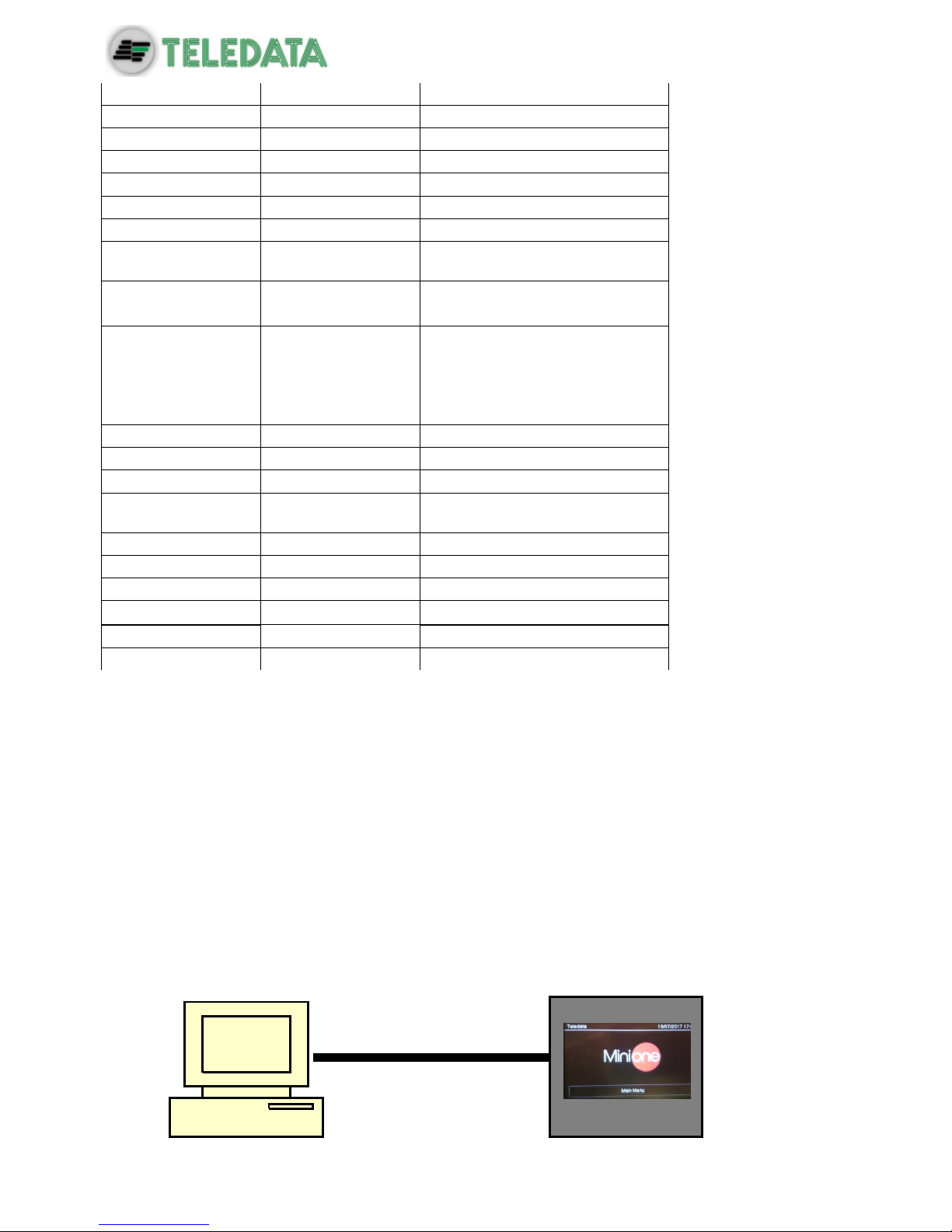
7.7 Connection to host computer
The control panel can be connected to a host computer by means of a Point to Point
connection or online by means of an appropriate LAN interface.
7.7.1 Point to Point connection
Below an example of point-to-point connection.

ONEMINI
FIRE ALARM CONTROL PANEL
USER AND INSTALLATION MANUAL - REV. 1.0.3 / 2018
PAGE 31
These types of configuration can be carried out through serial port that connect the host
computer directly to the control panel through the connector P1.
A connection tabel is provided below.
Connection:
Central Side
Connection
PC side
7 Jumpered with 8
7 Jumpered with 8
2
Connection with
2
3
Connection with
3
5
Connection with
5
It can be used for point-to-point connections with the program host to download a new
firmware version.
7.7.2 LAN or WAN connection
Below an example of network connection.
With this configuration it is possible to connect one or more control panel in a LAN or WAN
environment and monitor them from a host provided with centralized supervision functionality.
LAN OR
WAN
ONEMINI
FIRE ALARM CONTROL PANEL
USER AND INSTALLATION MANUAL - REV. 1.0.3 / 2018
PAGE 32
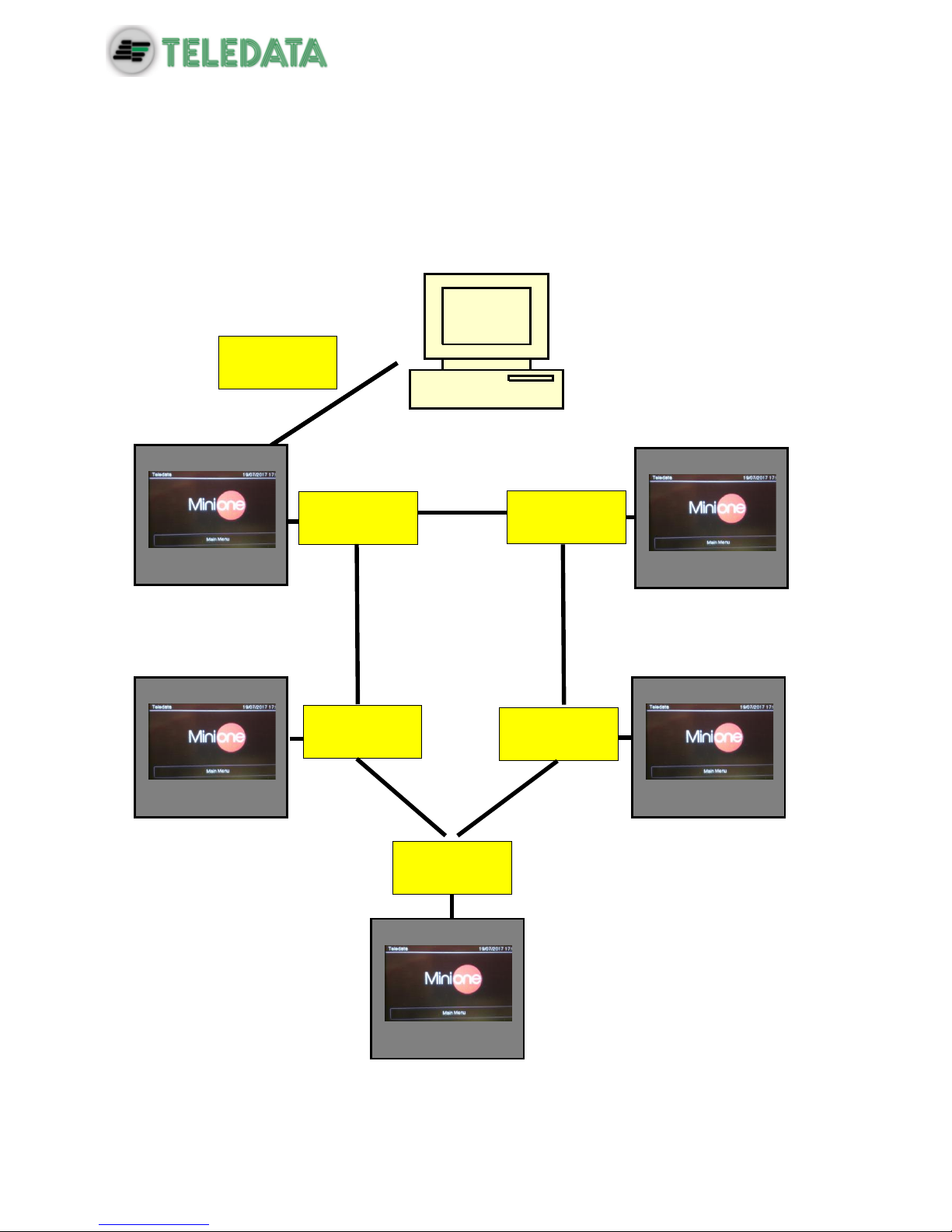
7.7.3 ONEMINI control panel ring network
More than one ONEMINI control panel may be connected together in a ring network on a
dedicated bus, by installing the optional ONERING network card.
In this network, events and alarms can be shared.
Below an example of ring network connection.
PT-LAN
Card
ONERING
Card
ONERING
Card
ONERING
Card
ONERING
Card
ONERING
Card
ONEMINI
FIRE ALARM CONTROL PANEL
USER AND INSTALLATION MANUAL - REV. 1.0.3 / 2018
PAGE 33
7.8 Power supply
7.8.1 Network input features
The control panel has to be installed according to the national installation standards.
It is requested to carry out a connection to a separated AC line that has to be marked with
the label FIRE SYSTEM.
Use a double-pole switch minimum 6A.
The connection wires have to have a proper section area and a minimum insulation of 600V.
The power supply input has to have the following features:
Supply voltage 230 Vac +/- 10%
Frequency 50/60 Hz
7.8.2 Grounding features
The grounding installation has to be carried out according to the CEI and ISPLES standards
and with a resistance lower than 10Ω.
7.8.3 Panel power supply features
Following features are useful for the system installation:
Output operating voltage 27.6 V - Max. 500mA
Voltage of battery charger 27.6 V- Max. 900mA
Low battery threshold 21.6 Volts
Battery release threshold 20.4 Volts

ONEMINI
FIRE ALARM CONTROL PANEL
USER AND INSTALLATION MANUAL - REV. 1.0.3 / 2018
PAGE 34
The battery charger section works as follows:
In case of power supply missing, the control panel is fed by the backup batteries. The
green LED turns off.
If the battery voltage drops below the low-battery threshold, an acoustic (buzzer) and
visual (on-screen message) signal are activated
In this situation, to restart the control panel, restore the network power supply.
If no battery is installed, at the first battery control carried out periodically by the
control panel, an acoustic (buzzer) and visual (on-screen message) signal are
activated to signal that the batteries in the control panel are missing.
If the battery's internal resistance (including the resistance due to contacts and cables)
is higher than 800 mΩ, the control panel will emit an acoustic (buzzer) and optical (onscreen message) alarm.
The value of internal resistance is refered to 7,2Ah batteries.
As far as the operating +24 V power supply section for external loads is concerned:
The voltage output is protected against short circuits.
In case of a short circuit an acoustic (buzzer) and visual (on-screen message) signal is
activated.
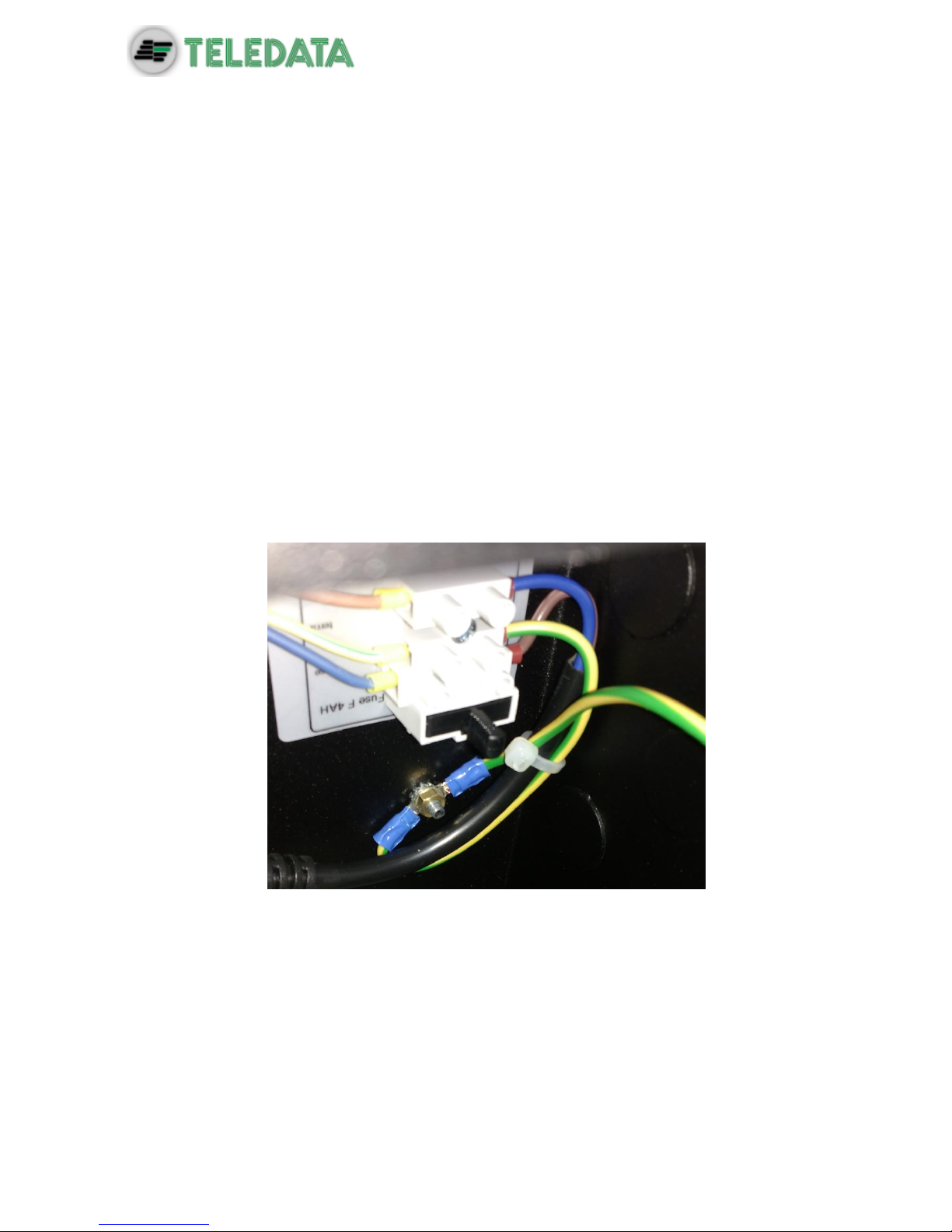
7.9 Panel internal cabling
The panel internal cabling has to be done in such way to be easily accessible in case of
future maintenance.
The cables can enter into panel unit through the holes provided on the upper part of the box
and on the back.
Cable outlet for 22 mm diameter must be use.
It is important to connect the cable shields to an earth terminal in the panel mechanics.
For closed loops, connect only one side of the shield, leaving the other side disconnected.

ONEMINI
FIRE ALARM CONTROL PANEL
USER AND INSTALLATION MANUAL - REV. 1.0.3 / 2018
PAGE 35
Below a cabling example of a complete panel is shown.

ONEMINI
FIRE ALARM CONTROL PANEL
USER AND INSTALLATION MANUAL - REV. 1.0.3 / 2018
PAGE 36
8. Control panel
The control panel includes the following elements:
Area
Description
1
Status led
2
Graphic interface (touch screen)
3
Zone Led
8.1 Status led
The following led are on the control panel:
Name
Color
Description
Fire
Red
Fire alarm from at least a device in the system
Fault
Yellow
Generic fault
Disablements
Yellow
Devices or peripherals disabled
Mon. Out. Act.
Yellow
Monitored output activated
Mon Out. Dis.
Yellow
Monitored output disabled
Fault Mon. Out.
Yellow
Monitored output fault
CPU fault
Yellow
CPU fault
Power
Green
Main Power supply 220V
Test
Yellow
At least one device under test
Silenced
Yellow
Alarm silenced
Ext. Activation
Yellow
Extinguishing circuit activated (not yet available)
Ext. Release
Yellow
Extinguishing circuit released (not yet available)
ONEMINI
FIRE ALARM CONTROL PANEL
USER AND INSTALLATION MANUAL - REV. 1.0.3 / 2018
PAGE 37
Name
Color
Description
Ext. Out Serv.
Yellow
Extinguishing circuit fault (not yet available)
Ext. Locked
Yellow
Extinguishing circuit locked (not yet available)
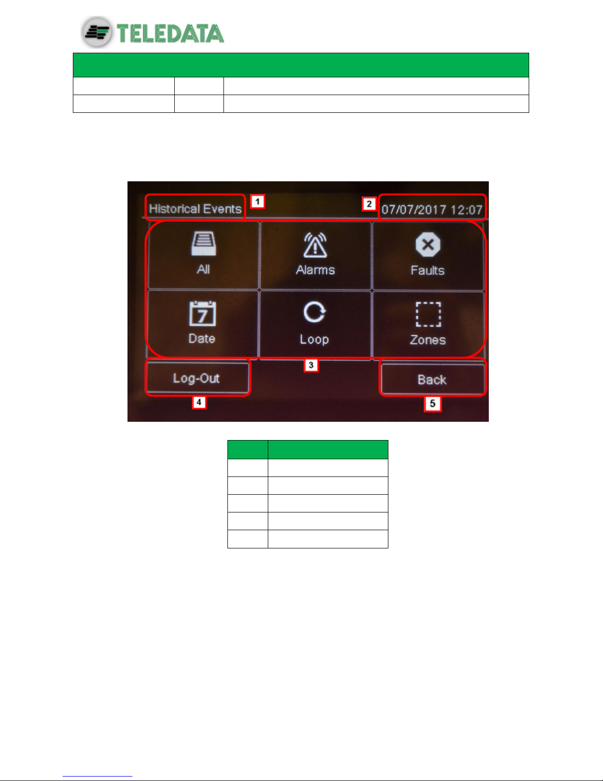
8.2 Graphic interface
The following elements are always displayed in all menus:
Area
Description
1
Page name
2
Unit date and time
3
Specific page content
4
Exit key
5
Back key
8.3 Types of users
The panel can be used by three different types of users:
User that can:
view system events
silence the panel and alarms
reset the panel and alarms
disable devices
test installed devices
export log events to USB

ONEMINI
FIRE ALARM CONTROL PANEL
USER AND INSTALLATION MANUAL - REV. 1.0.3 / 2018
PAGE 38
device diagnostics
Programmer that can:
configure and initialize the unit
view system events
disable devices
test installed devices
add and configure new devices
add new expansion boards to the unit
Technical support that can:
carry out all operations reserved to Technical support personnel.
Each operator can only open the screens required to run their permitted operations.
Any operator can view the system status and current events because these operations are
directly accessible from the Main page which is not password protected.
8.4 Access levels
As described by EN54/2, there are four access levels to the control panel:
Level 1: no access code is required
Level 2: reserved to Users (up to maximum three operators); an access code is
required
Level 3: reserved to Programmers; an access code is required (and jumper JP3
must be closed)
Level 4: reserved to Technical support; a wired PC connection is required. NO
ONEMINI
FIRE ALARM CONTROL PANEL
USER AND INSTALLATION MANUAL - REV. 1.0.3 / 2018
PAGE 39
9. Basic operations for any operator
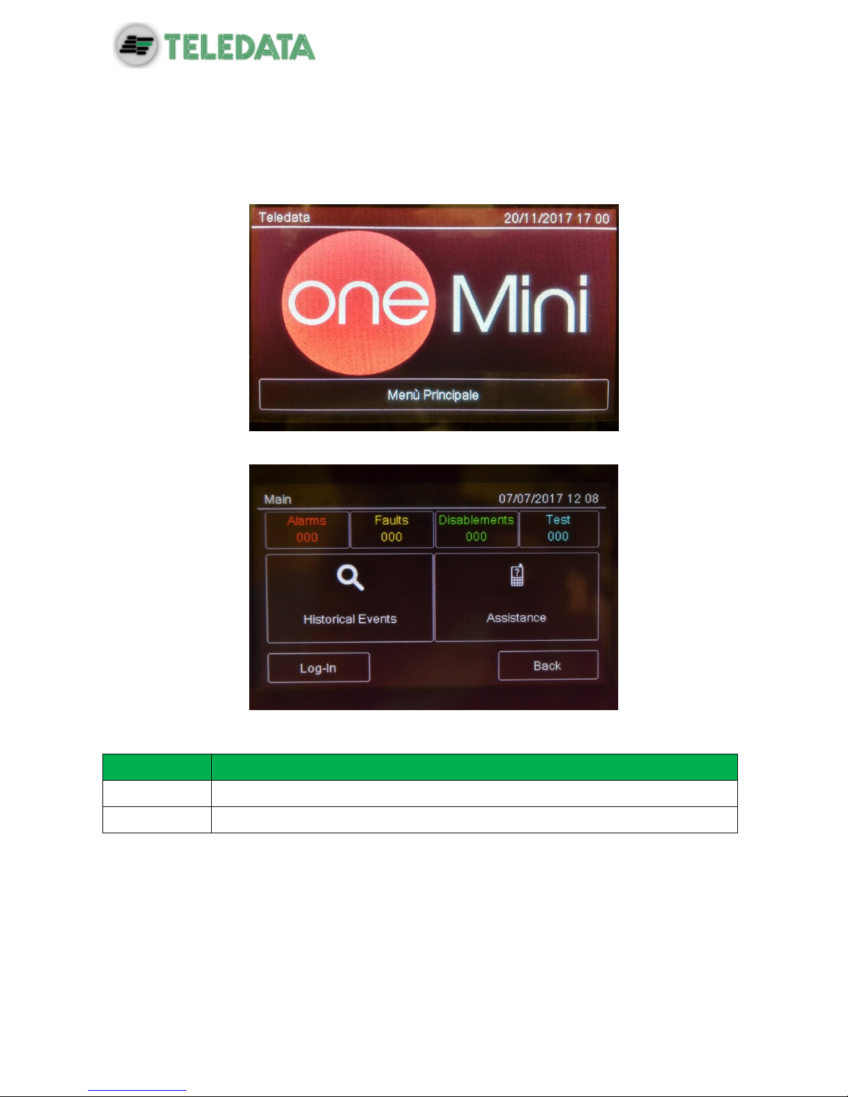
9.1 View basic information
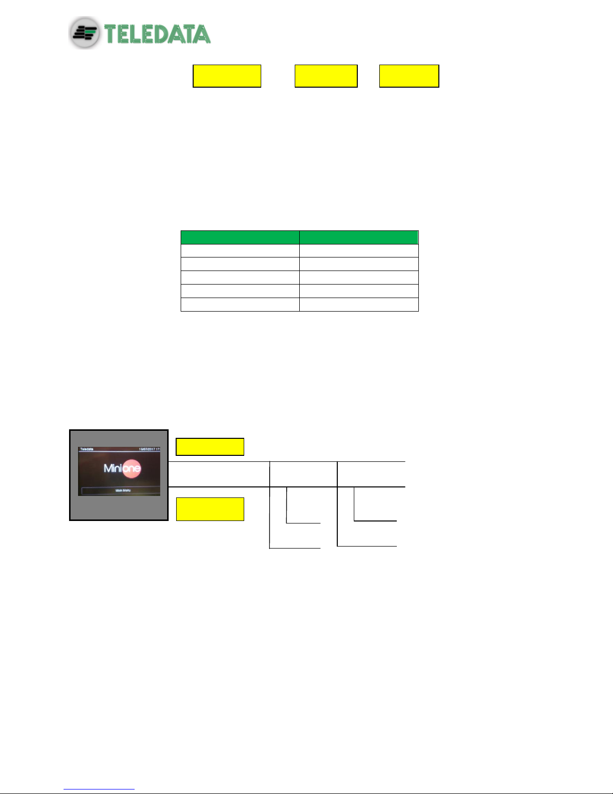
The home page is viewed when turned on if no events have occurred:
Press Main Menu to view it:
The menus in this page can be opened without entering any code.
Options
Menu
Function
Events
Opens the Events menu.
Assistance
Opens the Assistance page.
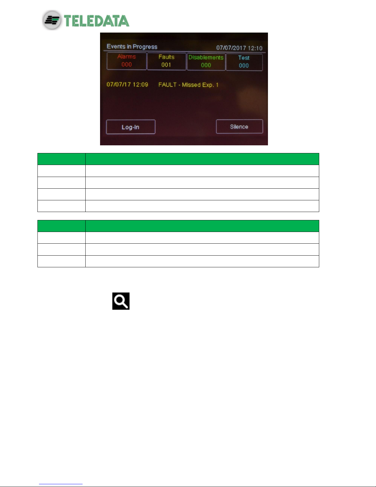
If any type of event has occurred, the Current events page is displayed when turned on.
ONEMINI
FIRE ALARM CONTROL PANEL
USER AND INSTALLATION MANUAL - REV. 1.0.3 / 2018
PAGE 40
Fields
Field
Description
Alarms
Displays the number of devices in alarm.
Faults
Displays the number of devices in fault status.
Exclusion
Displays the number of devices disabled.
Test
Displays the number of devices under test.
Options
Option
Function
Log – in
To open unit functions with a login code.
< >
To scroll through the pages that display all events.
Silence
To mute the panel buzzer (but not device alarms).
9.1.1 Viewing events
Main menu -> Events
The Events menu lets you view events logged by category.

ONEMINI
FIRE ALARM CONTROL PANEL
USER AND INSTALLATION MANUAL - REV. 1.0.3 / 2018
PAGE 41

ONEMINI
FIRE ALARM CONTROL PANEL
USER AND INSTALLATION MANUAL - REV. 1.0.3 / 2018
PAGE 42
Procedures
To view all events:
Select All: a list of all events is displayed.
To view all alarms:
Select Alarms: a list of all alarms is displayed.
To view all faults:
Select Faults: a list of all faults is displayed.
To view events on a specific day:
Select Date: the Log by Date screen appears.
Set the date of the events to be viewed.
Press Save to confirm: all events on the selected day are displayed.
To view events in a specific loop:
Select Loop: the Log by Loop screen appears.
Select the loop of the events to be viewed.
Press Save to confirm: all events in the selected loop are displayed.
To view events in a specific zone:
Select Zone: the Log by Zone screen appears.
Select the zone of the events to be viewed.
Press Save to confirm: all events in the selected zone are displayed.
:it’s possible to enter in Events menu choising one of the box show in main page;
we can only see the events related to the events choise.

ONEMINI
FIRE ALARM CONTROL PANEL
USER AND INSTALLATION MANUAL - REV. 1.0.3 / 2018
PAGE 43
9.1.2 Viewing assistance information
Main menu -> Assistance
Information required to receive assistance is displayed in this page.
ONEMINI
FIRE ALARM CONTROL PANEL
USER AND INSTALLATION MANUAL - REV. 1.0.3 / 2018
PAGE 44
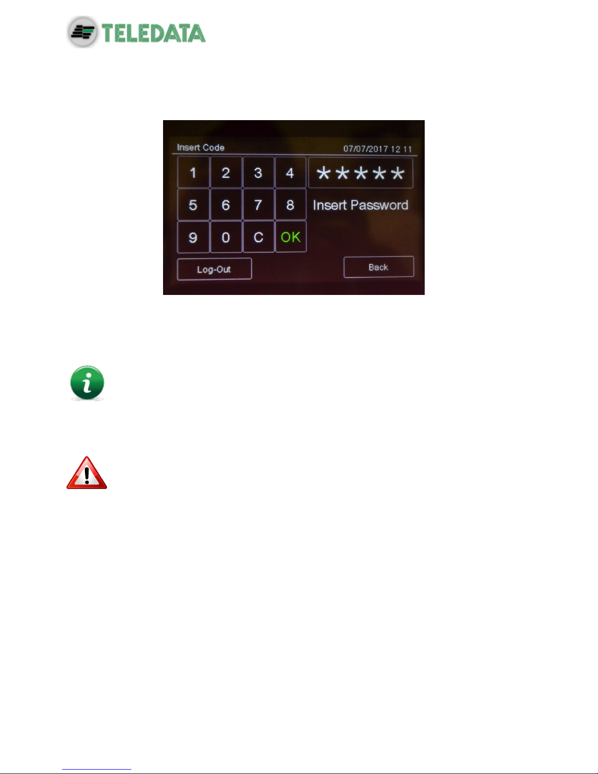
9.2 Login
Main page -> Log-in
Default settings
The following codes are set by default:
User code: 22222, 22223, 22224
Programmer code: 33333
Default user profile passwords 22223 and 22224 are disabled. For instructions
on how to enable them, see Enabling users and changing login codes).
Procedure
1. Insert the five digits of the code.
2. Press OK to confirm: the relevant menu is displayed according to the entered code.
Change the password as soon as possible to avoid unauthorized access to the
system (see 11.2 Enabling users and changing login codes).
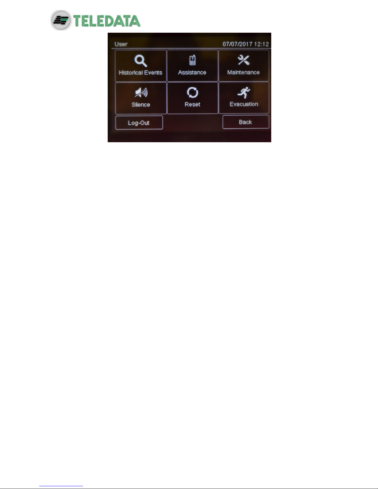
User menu
ONEMINI
FIRE ALARM CONTROL PANEL
USER AND INSTALLATION MANUAL - REV. 1.0.3 / 2018
PAGE 45

ONEMINI
FIRE ALARM CONTROL PANEL
USER AND INSTALLATION MANUAL - REV. 1.0.3 / 2018
PAGE 46
Programming menu
Procedures used by the various operators who work on the unit are described below.
This icon identifies functions reserved to the User.
This icon identifies functions reserved to the Programmer.
ONEMINI
FIRE ALARM CONTROL PANEL
USER AND INSTALLATION MANUAL - REV. 1.0.3 / 2018
PAGE 47
10. Configuration
The functions described below can only be run by authorized operators who
have a specific system login code to the task to be performed.
10.1 Setting up the panel
The following functions are reserved to the Programmer.
To set up the panel after installation:
set the number of installed expansion boards,
set device addresses,
set connected device names and features,
group devices in zones,
set relations between zones,
create logic functions to turn on outputs,
set output activation,
set the calendar.
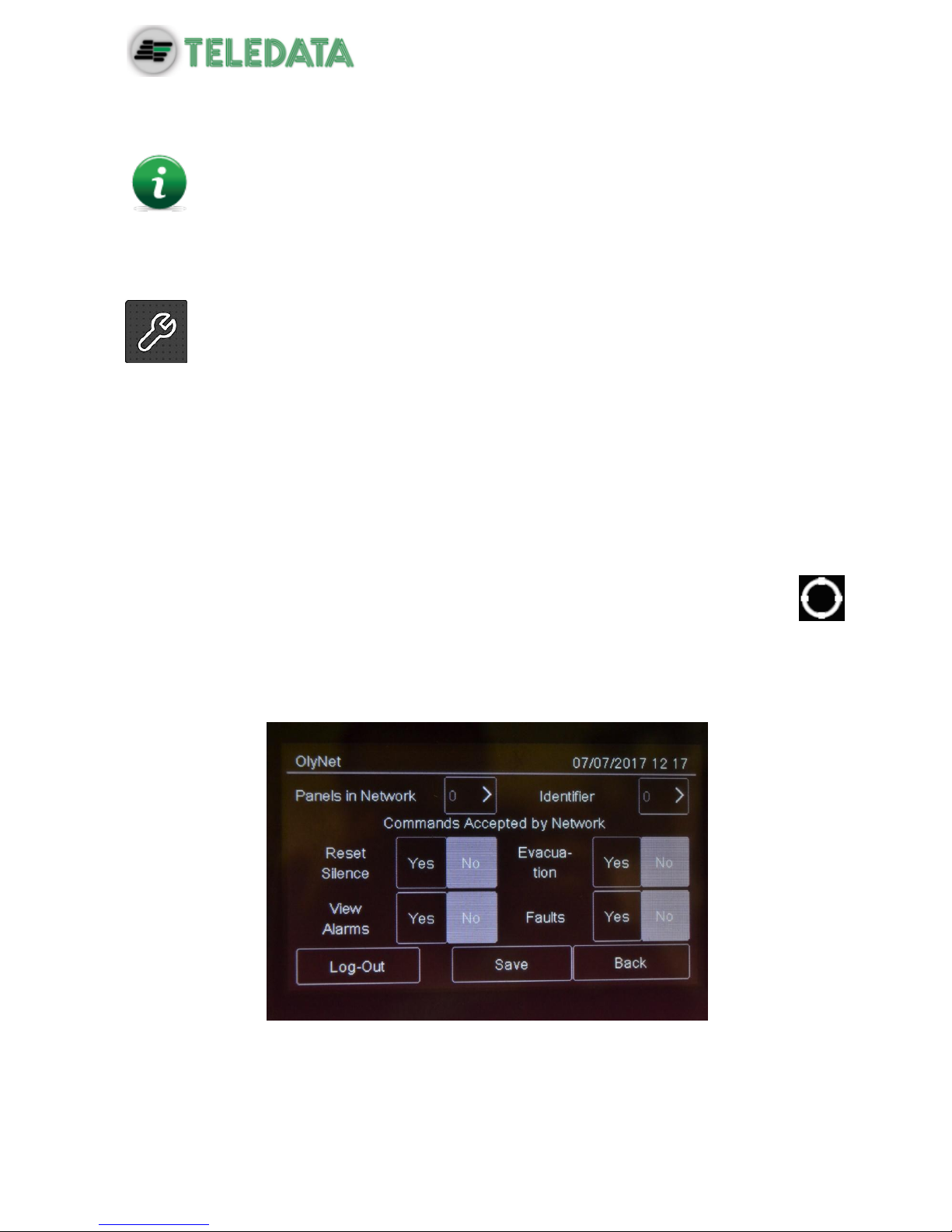
10.1.1 Programming Menu -> Configure -> System -> Additional Cards -> OlyNet
This function allows to configure all the necessary parameters for the correct functionality of
the ONERING system. In order to have this functionality, it is necessary to have installed in
the panel an OneRing additional card, and the panel is connected into a ring with other
ONEMINI
Procedura
1. Select the quantity of panels connected into the ring.
2. Select the single panel and confirm the model and the quantity of loops used.

ONEMINI
FIRE ALARM CONTROL PANEL
USER AND INSTALLATION MANUAL - REV. 1.0.3 / 2018
PAGE 48
3. Set the ID of the panel being configured.
4. Set the commands accepted from the network.
5. Press Save to confirm.
10.1.2 Run auto-addressing
Programming menu -> Configure -> Auto Addr.
Function currently unavailable.
This function will automatically set an address to all devices connected to the panel, without
using the hand programmer FDVPU1000.
10.1.3 Run self-programming
Programming menu -> Configure -> Auto Progr.
This function will search for and save all devices connected to the panel.
Procedure
Select the required loop: self-programming will start and the found devices will be displayed
as illustrated in the example.

ONEMINI
FIRE ALARM CONTROL PANEL
USER AND INSTALLATION MANUAL - REV. 1.0.3 / 2018
PAGE 49
10.2 Detectors configuration
The following functions are reserved to the Programmer.
Programming menu -> Configure -> Devices/Zones -> Detectors
With this function it is possible to:
add a detector
edit an already added detector
copy a detector settings to one or more consecutive detectors
delete a detector
Settings
Detector parameters to be set are described below.
Parameter
Description
Name
Detector identification name
Type
Type of connected detector (Optical, Thermal, Optical/Thermal)
Radio
Identifies wireless devices. With wireless devices, an FDW2W wireless
translator must be installed.
Verify Alarms
Enables an alarm verification procedure, for an amount of time that can
be programmed using parameter Verify seconds.
Verify
seconds
Interval, in seconds, during which the detector has to remain in alarm
before the panel will display the fire alarm.
If set to zero, the panel will go to alarm status only when it receives
three consecutive alarms from the detector within 60 seconds from the
arrival of the first one. The first two alarms received will be ignores by
the panel and will reset the detector.
Sensitivity
24 H: the level of sensitivity remains the set one for the entire day.

ONEMINI
FIRE ALARM CONTROL PANEL
USER AND INSTALLATION MANUAL - REV. 1.0.3 / 2018
PAGE 50
Parameter
Description
management
(only for
smoke
detectors)
Night: sensitivity increases by one step during the night.
Fixed: fixed sensitivity set to Medium High.
If the Night management is selected, it is also necessary to set the
Weekly Trend parameter.
Sensitivity
Detector level of sensitivity (Low, Medium Low, Medium High, High)
Weekly trend
Sets the weekly trend for the detector sensitivity management.
(see Setting weekly trends).
Deactivate
part
(only for multi
detector)
Day: select the part to deactivate it (smoke or thermal)
Night: select the part to deactivate it (smoke or thermal)
If this feature is used, it is also necessary to set the Weekly Trend
parameter.
Weekly trend
Sets the weekly trend for the deactivation of part of the detector. (see
10.8.5 Setting weekly trends).
Procedures
To add a sensor:
1. Select the Add option: a list of loops in the system is displayed.
2. Select the loop where the sensor has to be added: a list of sensors in the loop is
displayed.
3. Select an unused sensor number: the sensor settings window is displayed.
4. Enter the required settings.
5. Press Next to move to the next screen.
6. Press Save to confirm.

ONEMINI
FIRE ALARM CONTROL PANEL
USER AND INSTALLATION MANUAL - REV. 1.0.3 / 2018
PAGE 51
To edit a sensor:
1. Select the Edit option: a list of loops in the system is displayed.
2. Select the loop that contains the sensor.
3. Select the required sensor.
4. Edit settings.
5. Press Save to confirm.
To delete a sensor:
1. Select the Delete option: a list of loops in the system is displayed.
2. Select the loop that contains the sensor.
3. To delete a single sensor, press the sensor twice.
4. To delete several consecutive sensors, press the first and last module in the interval.
5. Press Save to delete the sensor or sensors.
To copy a sensor:
1. Select the Copy option: a list of loops in the system is displayed.
2. Select the loop that contains the sensor to be copied
3. Select the sensor to copy settings from.
4. Select the first sensor in the group to copy settings to.
5. Select the last sensor in the group to copy settings to.
6. Press Save to apply settings to all selected sensors.

ONEMINI
FIRE ALARM CONTROL PANEL
USER AND INSTALLATION MANUAL - REV. 1.0.3 / 2018
PAGE 52
10.3 Modules configuration
The following functions are reserved to the Programmer.
Programming menu -> Configure -> Devices/Zones -> Modules
This function lets you:
add a module
edit an already added module
copy a module settings to one or more consecutive modules
delete a module
Settings
Following are the parameters to be set for all types of modules.
Parameter
Description
Name
Module identification name
Radio
Identifies wireless devices.
With wireless devices, a FDW2W wireless converter must be installed.
Type
Module type: Argus:(Input, Output, Expander); Apollo: (input, output, expander
,multi 1+1, multi 2+2, multi 3+3)
Following are the parameters to be set for an Input type module.
Parameter
Description
Alarm test
Enables an alarm verification procedure, for an amount of time that can be
programmed using parameter Verify seconds.
Test seconds
Interval, in seconds, during which the detector has to remain in alarm before the
panel will displayed the fire alarm.
If set to zero, the panel will go to alarm status only when it receives three
consecutive alarms from the detector within 60 seconds from the arrival of the
first one. The first two alarms received will be ignores by the panel and will
resets the detector.
Type
Module type (Input, Call point Gas)
Technologica
l
Identifies the alarm signal as "technological" and thus less critical. Setting a
module like technologic, it’s possible setting other 3 functions: Ground, Latching
and Pre-Allarm
Pre-alarm
Turns on the pre-alarm function
When a pre-alarm event is detected:
all output modules associated with the output zones where the pre-alarm was
triggered are turned on (see 10.5 Output zones),
the unit red led blinks,
if the pre-alarm is not reset during the pre-alarm time or an alarm triggers, the
panel red led turns on.
Latching
This function allows the automatic reset of the central once the 'input falls in the
stand-by condition. It is activated in case of technological monitoring or fault.

ONEMINI
FIRE ALARM CONTROL PANEL
USER AND INSTALLATION MANUAL - REV. 1.0.3 / 2018
PAGE 53
Parameter
Description
Fault
It is shown in the display Fault-Technology that has occurred on the
programmed module.
Following are the parameters to be set for an Output type module.
Parameter
Description
Type
Module type (Output, Flasher, Siren, Repeater LED).
Reset
sensors
This feature is usually used to reset conventional devices that are not connected
directly to the loop. Every time that the panel is reset, this output will be activated
for around 5 seconds.
Evacuation
on
If activated, this feature will activate the output in case of an user evacuation
command, also if its zone or the logic function where it is linked is not yet valid.
For Siren type modules only
Volume
(only for siren model FDVBLS100/32 or FDVBS100-AV/32) Siren volume level,
also set the tone.
Di seguito I parametri da impostare per configurare moduli di tipo Multi I/O
Parameter
Description
Type
Module type (Multi I/O 1+1,Multi I/O 2+2,Multi I/O 3+3).
Choose
device
This function is used to set devices for each line of input and output from the
form: we will have two devices (one inbound and one outbound) if the Multi I / O
is 1 + 1, 4 devices (two input and two outgoing) if the Multi I / O is 2 + 2, finally 6
devices (three input and three output) if the Multi I / O is 3 + 3.
Input type
Type of input module that can be inserted (input, throttle button)
Output type
Type of output module that can be inserted (output, flash, siren, led.rip.)
: it is important to remember that multiple modules occupy multiple addresses,
depending on whether 1 + 1, 2 + 2 or 3 + 3; this because the input / output occupy additional
subsequent virtual address to the address of the physical module.
Procedures
To add a module:
1. Select the Add option: a list of loops in the system is displayed.
2. Select the loop where the module is to be added: a list of all devices in use, both
modules and sensors, in the loop is displayed.
3. Select an unused module number (blank): the module settings window is displayed.
4. Enter the required settings.
5. Press Next to move to the next screen.

ONEMINI
FIRE ALARM CONTROL PANEL
USER AND INSTALLATION MANUAL - REV. 1.0.3 / 2018
PAGE 54
6. Press Save to confirm.
To edit a module:
1. Select the Edit option: a list of loops in the system is displayed.
2. Select the loop that contains the module.
3. Select the required module.
4. Edit settings.
5. Press Save to confirm.
To delete a module:
1. Select the Delete option: a list of loops in the system is displayed.
2. Select the loop that contains the module.
3. To delete a single module, press the module twice.
4. To delete several consecutive modules, press the first and last module in the interval.
5. Press Save to delete the module or modules.
To copy a module:
This function lets you apply settings for one module to several consecutive modules:
1. Select the Copy option: a list of loops in the system is displayed.
2. Select the loop that contains the module to be copied
3. Select the module to copy settings from.
4. Select the first module in the group to copy settings to.
5. Select the last module in the group to copy settings to.
6. Press Save to apply settings to all selected modules

ONEMINI
FIRE ALARM CONTROL PANEL
USER AND INSTALLATION MANUAL - REV. 1.0.3 / 2018
PAGE 55
10.4 Zones configuration
The following functions are reserved to the Programmer.
Tip: before starting these operations, make sure you have understood how the
various system elements interact. See 7.5.1 Relations between the elements of
the plant.
10.4.1 Programming menu -> Configure -> Devices/Zones -> Zones
A zone is a list of devices and events that are necessary to generate partitions of the system.
It is possible to link devices, loops, and events to a zone.
This function lets you:
link events, loops and devices to the the zones
set various zone operating parameters
link output modules to a zone
10.4.2 Link an event to a zoneSettings
Settings are described below.
Parameter
Description
Alarm
The zone is activated by an alarm of the linked devices.
Fault
The zone is activated by a fault of the linked devices.
Technol.
The zone is activated by a "technological” event of the linked devices.
Coincidence
Programmable by event, this parameter is the number of events that have to be
recorded in order to activate the zone.
Procedure
1. Select the Add option: a list of zones in the system is displayed.
2. Select the required zone.
3. Select the Events option.
4. Select the events and their coincidence to be linked to the zone.
5. Press Save to confirm.
10.4.3 Linking loops to zones
Settings
Settings are described below.
Parameter
Description
All system
If Yes, all system devices will be linked to the zone.
If No, select the loop that activates the zone.
Loop
Select the entire loop that will be associated with the programmed zone.

ONEMINI
FIRE ALARM CONTROL PANEL
USER AND INSTALLATION MANUAL - REV. 1.0.3 / 2018
PAGE 56
Procedure
1. Select the Add option: a list of zones in the system is displayed.
2. Select the required zone.
3. Select the Loop option.
4. Set the required parameters:
5. Press Save to confirm.
10.4.4 Linking devices to zones
Procedure
1. Select the Add option: a list of zones in the system is displayed.
2. Select the required zone.
3. Select the Device option.
4. Select the required loop: all devices in the loop are displayed.
5. Select all devices to be linked to the zone.
6. Press Back to save the selection.

ONEMINI
FIRE ALARM CONTROL PANEL
USER AND INSTALLATION MANUAL - REV. 1.0.3 / 2018
PAGE 57
10.4.5 Set zone operating parameters
This function lets you set weekly zone behavior. This is helpful to bypass the unit on certain
days or at certain times.
Settings
Settings are described below.
Parameter
Description
Zone name
Name assigned to the zone
Weekly trend
Autoexclusio
n
Weekly trend linked to the zone.
(see 10.8.5 Setting weekly trends).
protected
If set to Yes, you can set the times T1, T2, T2B and set the weekly survey of
trends.
T1
It is the warning phase; in the moment of its activation, the area is already in
alarm but the associated output are still not parties.
T2
And the investigation time to physically check the veracity alarm; T2B has the
same operation, but only if the warning comes from a button.
weekly trend
survey
By setting this parameter, you can program the zone protected or unprotected
during the week.
Procedure
1. Select the Add option: a list of zones in the system is displayed.
2. Select the required zone.
3. Select the Settings option.
4. Enter the required settings.
5. Press Save to confirm.
To verify that a zone is properly set as protected, also follow the following procedure:
1. Enter third level code 33333;
2. Select the Configure section;
3. Enter the System section;
4. Press the General Section;
5. Enter the Various section;
6. Verify that The terminals T1 and T2 are enabled; (Section 10.7.10 of this manual)
7. Perform the Log-Out;
8. Enter the second level code 22222;
9. Select the Maintenance section;
10. Select the Exclusions section;
11. Entering the section protected;
12. Verify that the area we have planned as protected is green

ONEMINI
FIRE ALARM CONTROL PANEL
USER AND INSTALLATION MANUAL - REV. 1.0.3 / 2018
PAGE 58
10.4.6 Link an output module to a zone
This function lets you directly link output modules to a zone. When the zone is triggered, the
output modules automatically turn on.
Settings are described below.
Parameter
Description
Silenceable
If Yes, the operator can deactivate the output module (i.e.: siren) by
entering a password.
If No, to deactivate the output, it is necessary to reset the panel.
Procedures
To add a zone:
1. Select the Add option: a list of zones in the system is displayed.
2. Select the required zone.
3. Select the Output Modules option.
4. Select the output module loop.
5. Select the required module.
6. Set the required parameters:
7. Press Save to confirm.
To edit a zone:
1. Select the Edit option: a list of zones in the system is displayed.
2. Select the zone to be edited.
3. To edit linked events see 10.4.2 Link an event to a zone for parameter descriptions.
4. To edit linked loops: see 10.4.3 Linking loops to zones for parameter descriptions.
5. To edit linked devices see 10.4.4 Linking devices to zones for parameter descriptions.
6. To edit operating parameters: see 10.4.5

ONEMINI
FIRE ALARM CONTROL PANEL
USER AND INSTALLATION MANUAL - REV. 1.0.3 / 2018
PAGE 59
Set zone operating parameters for parameter descriptions.
7. To edit output modules: see 10.4.6 Link an output module to a zone for parameter
descriptions.
To delete a zone:
1. Select the Delete option: a list of zones in the system is displayed.
2. Select the zone to be deleted
3. To delete a single zone, press the zone twice.
4. To delete several consecutive zones, press the first and last zone in the interval.
5. Press Save to delete the zone.

ONEMINI
FIRE ALARM CONTROL PANEL
USER AND INSTALLATION MANUAL - REV. 1.0.3 / 2018
PAGE 60
10.5 Output zones configuration
The following functions are reserved to the Programmer.
Programming menu -> Configure -> Devices/Zones -> Output Zones
This function lets you link output modules to output zones.
Settings
Settings are described below.
Parameter
Description
Activations
Event type that activates the zone (Alarm, Pre-alarm Gas)
Silenceable
If Yes, the operator can deactivate the output module (i.e.: siren) by
entering a password.
If No, to deactivate the output, it is necessary to reset the panel.
Procedures
To create an output zone:
1. Select the Add option: a list of output zones in the system is displayed.
2. Select the first available output zone.
3. Set the required parameters:
4. Press Next to continue.
5. Select the loop that includes the output module to be linked.
6. Select the output module to be linked to the output zone.
7. Press Save to confirm.
To edit an output zone:
1. Select the Edit option: a list of output zones in the system is displayed.
2. Select the output zone to be edited.
3. Edit settings.
4. for parameter descriptions.
5. Press Save to confirm.
To delete an output zone:
1. Select the Delete option: a list of output zones in the system is displayed.
2. Select the output zone to be deleted
3. Press Save to delete the output zone.

ONEMINI
FIRE ALARM CONTROL PANEL
USER AND INSTALLATION MANUAL - REV. 1.0.3 / 2018
PAGE 61
10.6 Logic functions configuration
The following functions are reserved to the Programmer.
Programming menu -> Configure -> Devices/Zones -> Logic functions
Logic functions are cause and effect relations between events that occur in the panel. Logic
functions can put the following into relation:
detectors
modules
zones
alarms coming from the OlyNet system
events (not yet available)
logic functions
For example, you can create a logic function in which the activation of a series of zones
(inputs) activates specific outputs.
Logic operators
It is possible to link various inputs by using these logic operators:
AND
OR
NOT
XOR
Example of how to use logic operators
For each operator, below you can find an example of how they work. In these examples only
two inputs elements where considered.
AND
OR
NOT XOR
A B Y A B Y A Y A B Y 0 0 0 0 0 0 0 1 0 0 0 0 1 0 0 1 1 1 0 0 1 1 1 0 0 1 0 1 1 0 1 1 1 1 1 1 1 1 1
0

ONEMINI
FIRE ALARM CONTROL PANEL
USER AND INSTALLATION MANUAL - REV. 1.0.3 / 2018
PAGE 62
Settings
Settings are described below.
Parameter
Description
Detectors
Member loop and address
Modules
Member loop and address
Zone
Zone number
ONERING
Select the interessed panel and the necessary device (detector, module, zone,
ecc)
Event
Select the event type.
Detector:
Allarm
Fault
Disablements
Module:
Allarm
Pre-Allarm
Fault
Disablements
Technological
Logic
function
Number of another logic function that activates this one.
Delay
Delay time, in seconds, between logic function activation and output activation.
Length
Output activation time, in seconds.
If set to 0000, the outputs will remain active until the operator will reset them.
Output Zone
Associate
Outputs activated by logic functions.
These outputs must already be programmed (see 10.5 Output zones).
Procedures
To create a logic function:
1. Select the Add option: a list of available logic functions is displayed.
2. Select the first available logic function: the page where the logic function can be built
appears.

ONEMINI
FIRE ALARM CONTROL PANEL
USER AND INSTALLATION MANUAL - REV. 1.0.3 / 2018
PAGE 63
3. Press the input that will activate the logic function. The windows required to identify
the device, event or logic function appear according to the selected input.
4. For devices only, select the input status that will activate the function.
5. Build the logic relations between the events.
In the example, the logic function will be activated when sensor 001 in loop 1 triggers an
alarm and detector 009 in loop 1 is in pre-alarm.
6. Press Next to move to the next window.
7. Set the required parameters.
8. Associate Output Zone

ONEMINI
FIRE ALARM CONTROL PANEL
USER AND INSTALLATION MANUAL - REV. 1.0.3 / 2018
PAGE 64
9. Press Save to confirm.
To edit a logic function:
1. Select the Edit option: a list of available logic functions is displayed.
2. Select the logic function to be edited.
3. Edit settings.
4. Press Save to confirm.
To delete a logic function:
1. Select the Delete option: a list of available logic functions is displayed.
2. Select the logic function to be deleted
3. Press Save to delete the logic function.
ONEMINI
FIRE ALARM CONTROL PANEL
USER AND INSTALLATION MANUAL - REV. 1.0.3 / 2018
PAGE 65
10.7 Setting system parameters
The following functions are reserved to the Programmer.
10.7.1 Setting the language
Programming menu -> Configure -> System -> General ->
Select the required language: the selected language is immediately applied.
The available languages (from version 0.0.A00) are:
Italian
English
Turkish
French
optional are available, by updating the firmware , these languages
Farsi
Arabic
Polish
Estonian
Romanian
Portuguese
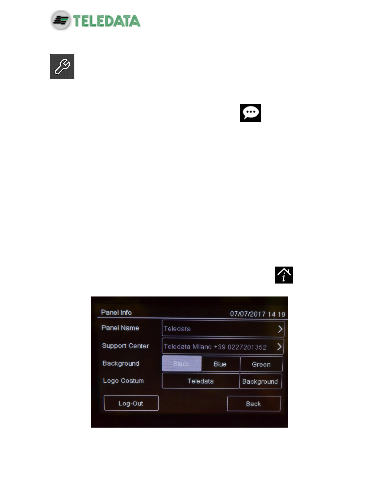
10.7.2 Entering panel information
Programming menu -> Configure -> System -> General -> Panel info

ONEMINI
FIRE ALARM CONTROL PANEL
USER AND INSTALLATION MANUAL - REV. 1.0.3 / 2018
PAGE 66
Settings
Settings are described below.
Parameter
Description
Panel name
Name assigned to the unit
Support
center
Service center contact data
Background
Control panel background color (black, blue, green)
Logo
Custom
Insert the password to personalize the panel with the customized logo.
10.7.3 Setting led and buzzer behavior
Programming menu -> Configure -> System -> General -> Buzzer-led
Finestra non valida,minione non ha retroilluminazione
Settings
Settings are described below.
Parameter
Description
Buzzer
Enables the panels buzzer. The buzzer sounds in the event of fault or
alarm.
Blinking led
Activates the blinking led function on devices installed on the loop. The
led blinks when queried by the panel.
Red led
Sets the device led blink color to red. The led blinks when queried by the
panel.

ONEMINI
FIRE ALARM CONTROL PANEL
USER AND INSTALLATION MANUAL - REV. 1.0.3 / 2018
PAGE 67
Parameter
Description
Activate in systems with sensors without built-in insulator, like those in the
SFxxxxE series..
Led
Backlight
Sets the panels back light color (green, white, blue). Press the set colour
to deactivate the LED backlight. TOGLIERE
10.7.4 Setting remote communications
Programming menu -> Settings -> System -> General -> Supervision
This function lets you set parameters for communications with the unit via LAN or RS-232.
This way the unit can be remotely monitored or programmed.
Settings
Settings are described below.
Parameter
Description
Baud Rate
Select one of the available options (9600, 19200, 38400, 57600).
Select the highest value for faster connections.
If a PT-LAN network card is installed, set the same parameter for the
network card.
Physical
address
Physical supervisor address
Logic
address
Logic supervisor address
Make sure the same values are set on the supervisor.

ONEMINI
FIRE ALARM CONTROL PANEL
USER AND INSTALLATION MANUAL - REV. 1.0.3 / 2018
PAGE 68
10.7.5 Setting loop features
Programming menu -> Configure -> System -> General -> Loop type
This function lets you specify for each loop in the system whether the loop is closed or open.
Procedure
1. Set the type of each loop.
2. Press Save to confirm.
10.7.6 Restoring factory settings
Programming menu -> Configure -> System -> Values Factory
This function lets you restore factory settings.
Once this procedure is launched it cannot be interrupted, all setting changes will
be deleted.
10.7.7 Setting peripheral features
Programming menu -> Configure -> System -> Peripherals
Function currently unavailable.
This function will allow to set the number of peripherals in the system connected via RS-485
serial line .
10.7.8 Exporting data
Programming menu -> Configure -> System -> USB -> Export
This function will allow to export various data from the panel to a USB support.
The panel is compatible with USB supports with a capacity until 16Gb formatted
in FAT32 with 4096 byte allocation table. It is necessary to format the device in
such way with a PC.

ONEMINI
FIRE ALARM CONTROL PANEL
USER AND INSTALLATION MANUAL - REV. 1.0.3 / 2018
PAGE 69
Procedure
Insert a compatible USB support.
Select “Configuration”, a file will be saved on the USB support in own format not
modifiable, with name “ONELOOP.CFG”.
If a file called “ONELOOP.CFG” is already existing in the inserted USB support root, it will be
overwritten, losing any previous past data exportation. Exporting time is around 3 seconds.
Selecting “Events”, a .csv format file will be saved on the USB support, that can be
opened with a software like Excel, called “EVNTLOG.CSV”.
If a file called “EVNTLOG.CSV” is already existing in the inserted USB support root, it will be
overwritten, losing any previous past data exportation. Exporting time depends on the
amount of events in memory. A panel with a full memory is around 60 seconds.
Selecting “Diagnostics”, it is necessary to select also the desired loop.
On the USB support a .csv format file will be created, that can be opened with a
software like Excel, called “1DIAGLP.CSV”, where the number in front of the file is the
selected loop of the panel.
If a file called “xDIAGLP.CSV” is already existing in the inserted USB support root, it will be
overwritten, losing any previous past data exportation. Exporting time depends on the
amount of devices connected to the desired loop. A loop with 240 devices connected, the
exporting time is around 240 seconds.
To avoid data corruption, do not disconnect the USB support, do not stop the
exporting procedure and do not turn off the panel.
10.7.9 Import data
Programming menu -> Configure -> System -> USB -> Import
This function will allow to import a previously saved configuration, file from a USB support to
the panel.

ONEMINI
FIRE ALARM CONTROL PANEL
USER AND INSTALLATION MANUAL - REV. 1.0.3 / 2018
PAGE 70
The panel is compatible with USB supports with a capacity until 16Gb formatted
in FAT32 with 4096 byte allocation table. It is necessary to format the device in
such way with a PC.
A configuration file called “ONELOOP.CFG” has to be existing in the inserted USB support
root. The panel configuration will be overwritten with the one in the USB support. The
importing time is around 20 seconds. After the importing, the panel will restart with the new
configuration.
To avoid data corruption, do not disconnect the USB support, do not stop the
exporting procedure and do not turn off the panel.
10.7.10 Various system settings
Programming menu -> Configure -> System -> General -> Miscellaneous
Settings
Settings are described below.
Parameter
Description
T1& T2
This parameter set if panel can control T1&T2 procedure or not

ONEMINI
FIRE ALARM CONTROL PANEL
USER AND INSTALLATION MANUAL - REV. 1.0.3 / 2018
PAGE 71
Parameter
Description
control
Silencing
time
Buzzer mute time in the event of persistent alarm. The buzzer restarts
after this time if the alarm is not reset.
Ground
Fault
Control
Runs the ground fault test to check for mains power ground dispersions
and loop signal grounding.
Activate this option to debug installation errors, especially
short circuits between grounding and unit signals (such as,
for example, a contact between cable shield and conductor).

ONEMINI
FIRE ALARM CONTROL PANEL
USER AND INSTALLATION MANUAL - REV. 1.0.3 / 2018
PAGE 72
10.8 Setting the calendar.
The following functions are reserved to the Programmer.
10.8.1 Setting the date and time
Programming menu -> Configure -> Date & Time -> Date and Time
Procedure
1. Set the current date and time.
2. Press Save to confirm.
10.8.2 Setting daylight savings time
Programming menu -> Configure -> Date & Time -> Summertime

ONEMINI
FIRE ALARM CONTROL PANEL
USER AND INSTALLATION MANUAL - REV. 1.0.3 / 2018
PAGE 73
Settings
Settings are described below.
Parameter
Description
Automatic
The panel automatically switches to daylight savings time.
Manual
Manually set the month and day daylight savings time starts and ends.
Not
managed
Function not enabled, no daylight savings time period is calculated.
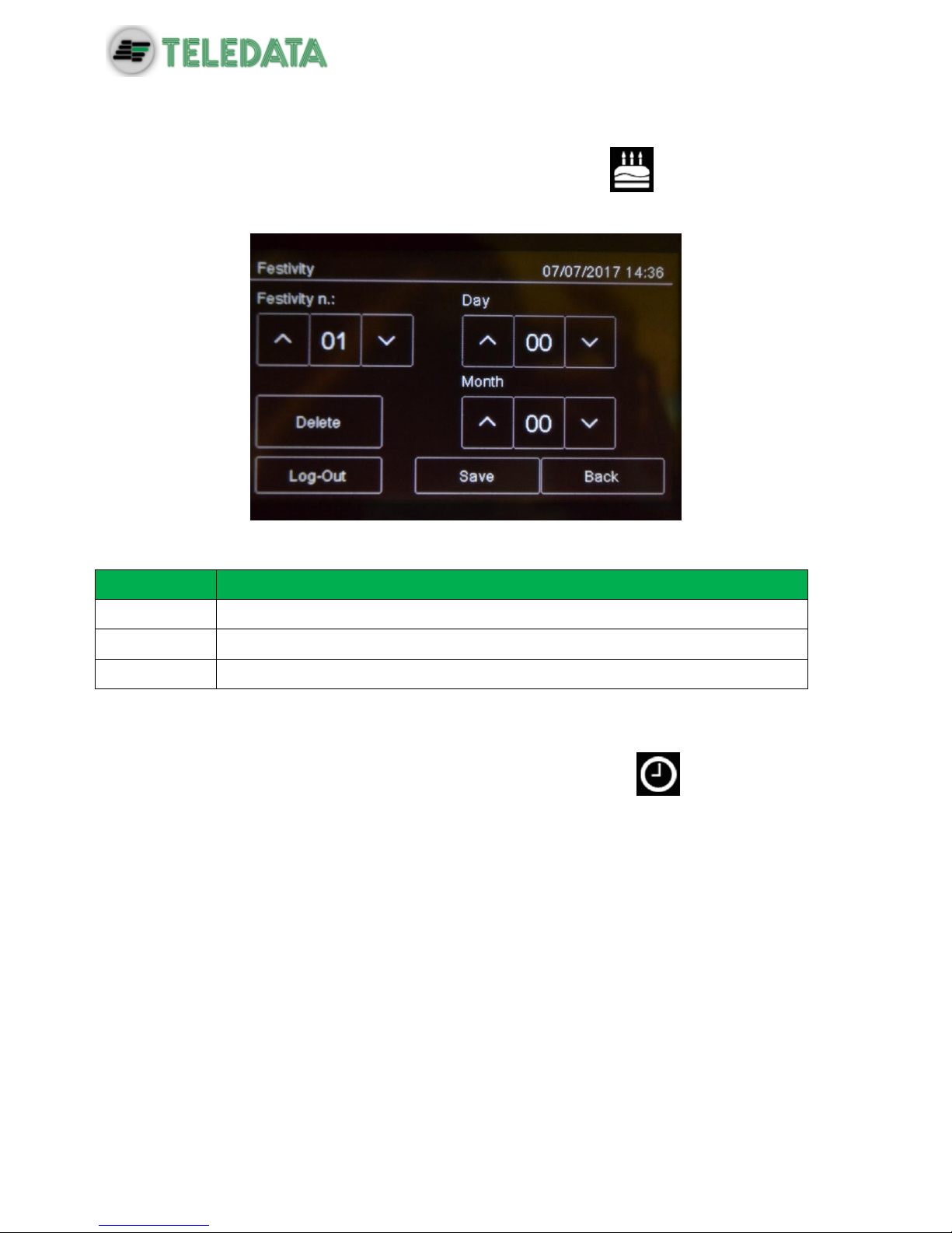
ONEMINI
FIRE ALARM CONTROL PANEL
USER AND INSTALLATION MANUAL - REV. 1.0.3 / 2018
PAGE 74
10.8.3 Setting holidays
Programming menu -> Configure -> Date & Time -> Holidays
This function lets you program holidays.
Settings
Settings are described below.
Parameter
Description
Holiday no.
Holiday ID (1-12)
Day
Holiday day
Month
Holiday month
10.8.4 Setting time intervals
Programming menu -> Configure -> Date & Time -> Time Slot ->
This function lets you set up to 255 daily time intervals.
Procedures
To create a new time interval:
1. Select the Add option: the list of time intervals is displayed.
2. Select a time interval not set.
3. Set the start date and time [1] and end date and time [2] for the time interval.
4. Press Save to confirm.
To edit an existent time interval:
1. Select the Edit option: the list of time intervals is displayed.
2. Select the time interval to be edited.
3. Change the start and end times.

ONEMINI
FIRE ALARM CONTROL PANEL
USER AND INSTALLATION MANUAL - REV. 1.0.3 / 2018
PAGE 75
4. Press Save to confirm.
To delete an existent time interval:
1. Select the Delete option: the list of time intervals is displayed.
2. Select the time interval to be deleted.
3. Press Save to confirm.
10.8.5 Setting weekly trends
Programming menu -> Settings -> Date & Time -> Weekly trends
This function lets you link previously created time intervals to days of the week.
Procedures
To create a new weekly trend proceed as following:
1. Select the Add option: the list of weekly trends is displayed.
2. Select a weekly trend not set.
3. Select the time interval to be linked for each day of the week. See 10.8.4 Setting time
intervals on how to create time intervals.
4. Press Save to confirm.
To edit an existent weekly trend:
1. Select the Edit option: the list of weekly trends is displayed.
2. Select the weekly trend to be edited.
3. Edit the time intervals linked to the days.
4. Press Save to confirm.
To delete an existent weekly trend:
1. Select the Delete option: the list of weekly trends is displayed.
2. Select the weekly trend to be deleted.
3. Press Save to confirm.

ONEMINI
FIRE ALARM CONTROL PANEL
USER AND INSTALLATION MANUAL - REV. 1.0.3 / 2018
PAGE 76
11. Use
11.1 Viewing events
The following functions are accessible to both the User
and Programmer.
Event Log Menu
The Event Log menu lets you view events logged by category. See 9.1.1 Viewing events for
a description of the displayed information.
11.1.1 Exporting data
User menu -> Maintenance -> Export -> Events
This function will allow to export the event memory from the panel to a USB support.
The panel is compatible with USB supports with a capacity until 16Gb formatted
in FAT32 with 4096 byte allocation table. It is necessary to format the device in
such way with a PC.
Procedura
Insert a compatible USB support by using a MiniUSB to USB adaptor.
Go to the declaired menu
Selecting “Events”, a .csv format file will be saved on the USB support, that can be opened
with a software like Excel, called “EVNTLOG.CSV”.
If a file called “EVNTLOG.CSV” is already existing in the inserted USB support root, it will be
overwritten, losing any previous past data exportation. Exporting time depends on the
amount of events in memory. A panel with a full memory is around 60 seconds.
To avoid data corruption, do not disconnect the USB support, do not stop the
exporting procedure and do not turn off the panel.

ONEMINI
FIRE ALARM CONTROL PANEL
USER AND INSTALLATION MANUAL - REV. 1.0.3 / 2018
PAGE 77
11.2 Enabling users and changing login codes
Only the Programmer operator can enable or disable user operator login. Each operator can
change their personal login code.
11.2.1 Programmer
Programming menu -> Configure -> Password
Procedures
To enable User login:
1. Set all Users who need to login to the unit to Yes.
2. Press Save to confirm.
To change the Programmer login code:
1. Select the Change option: the code change page is displayed.
2. Insert the new code.
3. Confirm the new code to save it.
11.3 Managing alarms
In case of alarm received from any device, the panel will activate immediately the internal
siren output and will turn on the red LED on the front panel.
The device in alarm status will turn on its red LED.
To avoid a loop overload, in case of more than one alarm, a maximum of 10 red
LEDs on the devices will be activated.
The following functions are reserved to the User

ONEMINI
FIRE ALARM CONTROL PANEL
USER AND INSTALLATION MANUAL - REV. 1.0.3 / 2018
PAGE 78
11.3.1 Mute alarms and the unit
User menu -> Silence
Once this key is pressed, it is transformed into Rearm.
This function lets you temporarily mute system and panel alarms to check if a fire has
actually broken out and reset them if necessary.
Procedures
In the event of false alarm:
Reset the panel (see 11.3.2 Reset alarms and the unit).
In the event of real alarm:
Press the Siren Reset key to turn sirens back on.
11.3.2 Reset alarms and the unit
User menu ->Reset
This function resets triggered alarms and the unit.
If alarms or faults are not restored before the reset, after it will still be shown on the display
from the central.
It’s possible to perform a reset Hardware through the appropriate button on the
master board.
11.3.3 Evacuation
User menu ->Evacuation
This feature will put the panel into evacuation mode, activating all the outputs/sirens properly
configured.
By activating the evacuation all the output modules programmed as “Activate evacuation”
(see 10.3 Modules) will be activated, even if their zone is not active, and if the logic function
where they are linked to is not yet valid.

ONEMINI
FIRE ALARM CONTROL PANEL
USER AND INSTALLATION MANUAL - REV. 1.0.3 / 2018
PAGE 79
11.4 Checking device status
The following functions are accessible to both the User
and Programmer.
11.4.1 Check loop status
Maintenance -> Loop -> Status
Procedure
Select the required loop: loop type and status are displayed.
11.4.2 Resetting a loop
Maintenance -> Loop -> Reset
Select the required loop: this is automatically reset.
11.4.3 Run device diagnostics
Maintenance -> Diagnostics
This function lets you check connected device cleanliness.
Sensor status
Sensor status is indicated by the following colors:
Color
Device conditions
Clean detector
Medium clean detector
Almost dirty detector
Dirty detector
Procedure
1. Select the required loop: all connected devices are displayed.
2. Press a single sensor to view details.

ONEMINI
FIRE ALARM CONTROL PANEL
USER AND INSTALLATION MANUAL - REV. 1.0.3 / 2018
PAGE 80
11.4.4 Diagnostics export.
User Menu -> Maintenance-> Export -> Diagnostics
This function will allow to export the device diagnostics connected to the panel, to a USB
support.
The panel is compatible with USB supports with a capacity until 16Gb formatted
in FAT32 with 4096 byte allocation table. It is necessary to format the device in
such way with a PC.
Procedure
Insert a compatible USB support.
Go to the declaired menu
On the USB support a .csv format file will be created, that can be opened with a
software like Excel, called “1DIAGLP.CSV”, where the number in front of the file is the
selected loop of the panel.
If a file called “xDIAGLP.CSV” is already existing in the inserted USB support root, it will be
overwritten, losing any previous past data exportation. Exporting time depends on the
amount of devices connected to the desired loop. A loop with 240 devices connected, the
exporting time is around 240 seconds.
To avoid data corruption, do not disconnect the USB support, do not stop the
exporting procedure and do not turn off the panel.
11.5 Testing devices
The following functions are accessible to both the User
and Programmer.
11.5.1 Running a Walk Test
Maintenance -> Test -> Sensors/Modules -> Walk Test
Walk test is used to check that the devices are able to generate an manually.
When devices are in this mode, the system does not generate any alarm and
does not run the relevant procedures.
Different types of tests can be run:
Single: used to test only one device.
Zone: used to test devices in a specific zone.
Loop: used to test devices in a the loop.
Test results
ONEMINI
FIRE ALARM CONTROL PANEL
USER AND INSTALLATION MANUAL - REV. 1.0.3 / 2018
PAGE 81
The results are indicated by a color for all tests.
Color
Device conditions
Test successfully completed.
Device still not gone to alarm status.
Procedures
To run a single test:
1. Press the Single option.
2. Select the device loop and address.
To run a zone test:
1. Press the Zone option.
2. Select the required zone.
To run a loop test:
1. Press the Loop option.
11.5.2 Testing the connection with modules and sensors
Maintenance -> Test -> Sensors/Modules -> Sensors/Modules
Device connection
Connection status is indicated by a color for all devices.
Color
Device conditions
Device correctly connected.
Device connection error
Procedures
To test the device connection:
1. Select the device address: the connection status with each loop device is displayed by
a color. The below example illustrates a correct communication with loop 1 sensor
229.
11.5.3 Identifying conflicts
Maintenance -> Test -> Conflicts
This function lets you check whether two devices have the same address on the loop, in the
system.
1. If several devices are displayed with the same address, change one.

ONEMINI
FIRE ALARM CONTROL PANEL
USER AND INSTALLATION MANUAL - REV. 1.0.3 / 2018
PAGE 82
11.5.4 Identifying mismatches
Maintenance -> Test -> Mismatch
This function lets you check whether the device on the loop correspond really to the device
typology configured in the panel (for example, whether a detector was programmed as a
module or vice versa).
1. Start mismatch test
2. Correct any found mismatch.
11.5.5 Testing led operations
Maintenance -> Test -> Led
This function lets you check whether all the LEDS on the panel and the RGB display values
are correctly working.
ONEMINI
FIRE ALARM CONTROL PANEL
USER AND INSTALLATION MANUAL - REV. 1.0.3 / 2018
PAGE 83
11.6 Disable system elements
The following functions are accessible to both the User
and Programmer.
Maintenance -> Exclusions/Inclusions
Disabled devices do not send any alarm or fault signal. This compromises system
safety. Only disable a device with strictly necessary and re-include it as soon as
possible.
This function lets you bypass and re-include one or more unit devices. This feature will ignore
any information received by the excluded device.
It is possible to disable:
devices
loop
zones
output zones
additional boards (Function not yet available)
Element conditions
Symbol
Element condition
Disabled element (detector in the example)
Enabled element (detector in the example)
11.6.1 Disabling/Enabling a device
Maintenance -> Exclusions/Inclusions -> Devices
Procedures
To disable a detector:
1. Select the device to be bypassed.
2. Press Save to confirm. Sensor 001 is bypassed in the example.
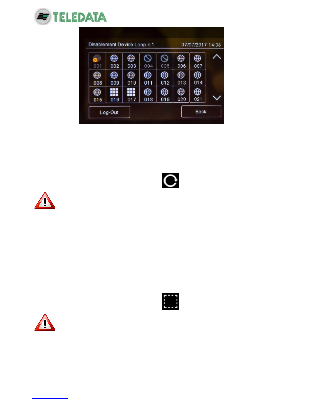
ONEMINI
FIRE ALARM CONTROL PANEL
USER AND INSTALLATION MANUAL - REV. 1.0.3 / 2018
PAGE 84
To enable a previously bypassed detector:
1. Select the bypassed device to be included.
2. Press Save to confirm.
11.6.2 Disabling/Enabling a loop
Maintenance -> Exclusions/Inclusions -> Loop
Warning: bypassing a loop automatically bypasses all devices connected to it.
Procedures
To disable the loop:
1. Press Save to confirm. Loop is bypassed.
To enable a previously bypassed loop:
1. Select the bypassed loop to be included.
2. Press Save to confirm.
11.6.3 Disabling/Enabling a zone
Maintenance -> Exclusions/Inclusions -> Zone
Warning: bypassing a zone automatically bypasses all connected loops and
relevant devices.
Procedures
To disable a zone:
1. Select the zone to be bypassed:

ONEMINI
FIRE ALARM CONTROL PANEL
USER AND INSTALLATION MANUAL - REV. 1.0.3 / 2018
PAGE 85
2. Press Save to confirm.
To enable a previously bypassed zone:
3. Select the bypassed zone to be included.
4. Press Save to confirm.
11.6.4 Disabling/Enabling an output
Maintenance -> Exclusions/Inclusions -> Outputs
Procedures
To disable an output:
1. Select Yes for each output to be bypassed.
2. Press Save to confirm.
3.
To enable an output:
1. Select No for each output to be included.
2. Press Save to confirm.
11.6.5 Disabling/Enabling a board
Maintenance -> Exclusions/Inclusions -> Additional boards
Function currently unavailable.
11.7 Modify a user password
The following functions are reserved to the User.
Maintenance -> Change password
This feature will permit to modify the password of the logged user.
To modify the User password:
1. Select the Change option: the code change page is displayed.
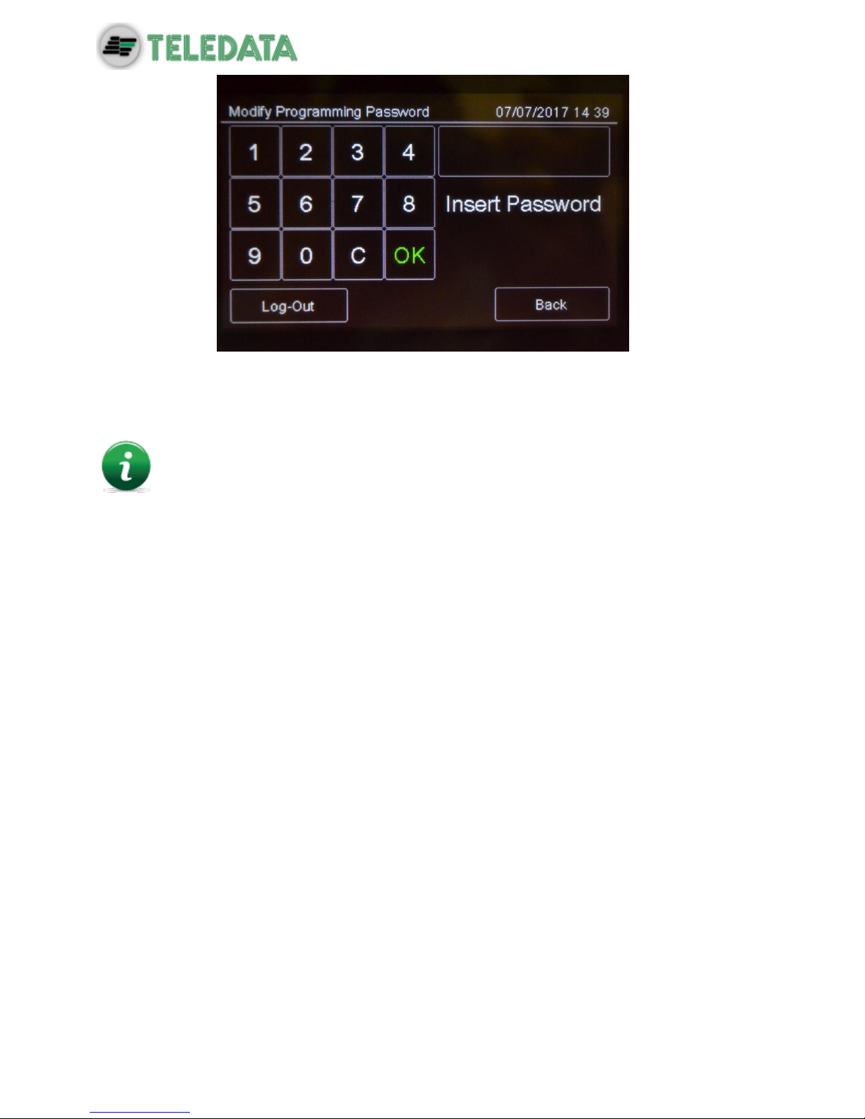
ONEMINI
FIRE ALARM CONTROL PANEL
USER AND INSTALLATION MANUAL - REV. 1.0.3 / 2018
PAGE 86
2. Insert the new code.
3. Confirm the new code to save it.
This new code must be used at the next login
Each user can modify their password. To activate other users (max 3) see
paragraph 11.2.
 Loading...