

Page 1
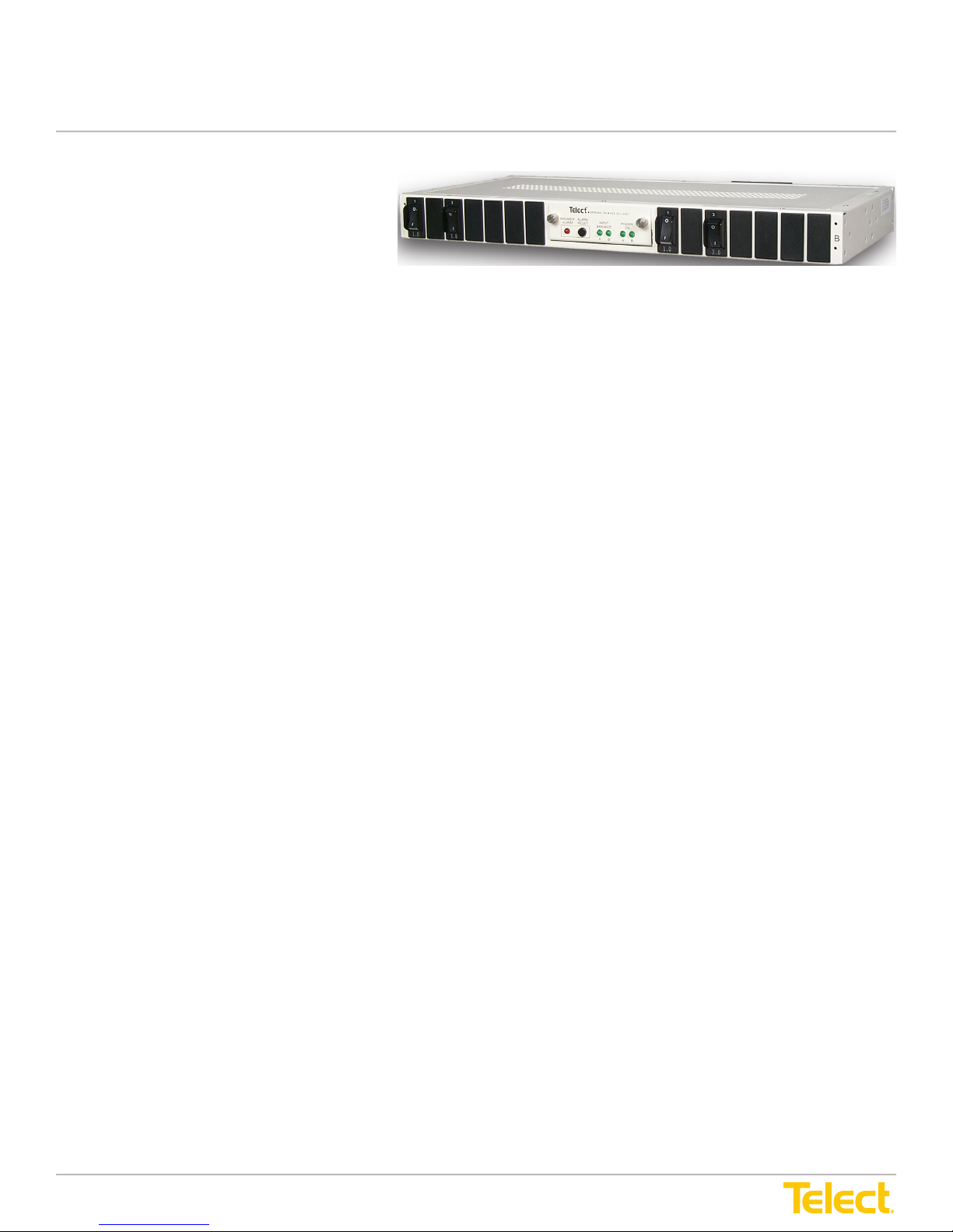
Dual 40/50/100A Congurable Breaker Panel
Power :: T009-5XXXXXXXXXXX
Installation Guide
Model T009-5XXXXXXXXXXX
Overview
The Telect dual-feed congurable breaker panel provides circuit breaker power protection for a variety of
telecommunications equipment. Panel includes up to 7 circuit breakers per side for a total maximum
continuous load of 40A, 50A or 100A:
• 40A with optional 50A thermal input breakers
• 50A without optional input breakers (screw-tight inputs)
• 100A without optional input breakers (compression inputs only)
White or black panels can be congured with any combination of 1A to 20A Carling, M-Series breakers
[oriented with the “on” symbol ( | ) at either the bottom or top], 50A thermal input breaker and either
screw-tight or compression input connectors. Screw-tight connectors can be oriented for sideways or
top-down wiring.
Feeds A and B are independent except for the replaceable alarm card which contains power and
alarm LEDs for both feeds. Also included are breaker alarm and power-fail relay terminals for wiring to
external indicators.
Hardware is included for ush or extended mounting in 19" or 23" relay racks. See “Accessories” (Page 7) for ordering
optional and replaceable items: output breakers, face plates, lugs, ETSI mounting kit and more.
© Telect, Inc., All Rights Reserved, 118267-3 A0
1.509.926.6000 :: telect.com
1
Page 2
Dual 40/50/100A Congurable Breaker Panel
Power :: T009-5XXXXXXXXXXX
Installation Guide
Specications
Mechanical Specications
Dimensions (nominal), without brackets* Width: 17.25" (43.82 cm)
Height: 1.75" (4.44 cm)
Depth: 8.00" (20.32 cm)
Weight without breakers 9 lbs (4.08 kg)
Weight, shipping 10.5 lbs (4.76 kg)
Mounting for standard racks EIA: 19" (48.2 cm)
WECO: 23" (58.4 cm)
ETSI: 21" (53.3 cm)
[Kit sold separately. See “Accessories” (Page 7).]
Ground terminals Quantity:
2
Stud:
Lugs:
Cable:
Torque:
Input terminals — Compressions Quantity:
Stud:
Lugs:
Cable:
Torque:
Input terminals — Phoenix-style screw-tight Slotted screwhead for wire clamping up to
#6 AWG, depending on input interruption
device. Torque screws to 14 in.-lb (~1.5 N•m).
Output terminals — Wire binding Quantity:
M5 with hex nut. [Use 8mm
(5/16 in.) socket.]
Single or dual-hole compression lug [5/8 in.
(1.59 cm) center to center]
Up to #10 AWG for single-hole lug
Up to #6 AWG for dual-hole lug.
(Conductor size depends on input
interruption device.)
20 in.-lb (~2.25 N•m), max.
4 — 2 BATT, 2 RTN
M5 with KEPS nut. [Use 8 mm
(5/16 in.) socket.]
Dual-hole compression lug
[5/8 in. (1.59 cm) center to center]
Up to #1 AWG, depending on input
interruption device
20 in.-lb (~2.25 N•m), max.
28 — 14 BATT, 14 RTN
Alarm terminals — Wire binding Quantity:
© Telect, Inc., All Rights Reserved, 118267-3 A0
1.509.926.6000 :: telect.com
Screw:
Cable:
Clearance:
Torque:
Screw:
Cable:
Torque
#6 Phillips** pan head
Up to #10 AWG
0.31 in. (.79 cm) between terminal barriers
9 in.-lb (1.02 N•m), max.
6
#4 Phillips** pan head
#30 to #16 AWG
4 in.-lb (0.45 N•m), max.
2
* See Page 11 for
exact dimensions
** Screws with
cross-recessed heads
Page 3
Dual 40/50/100A Congurable Breaker Panel
ALERT
!
Electrical Specifications
Operating voltages
–20 to –60 Vdc, +20 to +30 Vdc
Maximum input interruption device rating
125A for a 100A panel
60A for all other panels.
Maximum continuous input load rating (total)
100A per feed (with compression inputs but without 50A
thermal input breaker)
50A per feed (with screw-tight inputs but without 50A
thermal input breaker)
40A per feed (with 50A thermal input breaker)
Maximum output interruption device rating
20A per circuit breaker
Maximum continuous output load rating
16A per circuit breaker
Alarm contact ratings, continuous
2A at 30 Vdc 0.6A at 60 Vdc
Alarm board power ratings
@20V: 80mA (1.60W) @24V: 112mA (2.69W)
@27V: 120mA (3.24W) @30V: 122mA (3.66W)
@40V: 127mA (5.08W) @48V: 130mA (6.24W)
@54V: 133mA (7.18W) @60V: 136mA (8.16W)
Max. operating temperature at max. load ratings
55°C (131°F)
Min. operating temperature at max. load ratings
–10°C (14°F)
Ambient operating temp. at half-load
55°C (131°F)
Max. surface temperature of breakers at 26°C (79°F) am-
bient
35°C (95°F)
Max. panel heat dissipation at full load
18W per side at 1920W (40A x 48V) per side
20W per side at 2400W (50A x 48V) per side
42W per side at 4800W (100A x 48V) per side
Percentage of full load heat dissipation at nominal voltage
less than 1% of total load wattage
Power :: T009-5XXXXXXXXXXX
Installation Guide
Specications Cont.
Electrical Specications
Operating voltages –20 to –60 VDC, +20 to +30 VDC
Maximum input interruption device rating 125A for a 100A panel
Maximum continuous input load rating (total) 100A per feed (with compression inputs but without 50A
Maximum output interruption device rating 20A per circuit breaker
Maximum continuous output load rating 16A per circuit breaker
Alarm contact ratings, continuous 2A at 30 VDC 0.6A at 60 VDC
Alarm board power ratings @20V: 80mA (1.60W)
Max. operating temperature at max. load ratings 55°C (131°F)
Min. operating temperature at max. load ratings –10°C (14°F)
Ambient operating temp. at half-load 55°C (131°F)
Max. surface temperature of breakers at 26°C
(79°F) ambient
Max. panel heat dissipation at full load 18W per side at 1920W (40A x 48V) per side
Percentage of full load heat dissipation at
nominal voltage
60A for all other panels
thermal input breaker)
50A per feed (with screw-tight inputs but without 50A
thermal input breaker)
40A per feed (with 50A thermal input breaker)
@27V: 120mA (3.24W)
@40V: 127mA (5.08W)
@54V: 133mA (7.18W)
35°C (95°F)
20W per side at 2400W (50A x 48V) per side
42W per side at 4800W (100A x 48V) per side
Less than 1% of total load wattage
@24V: 112mA (2.69W)
@30V: 122mA (3.66W)
@48V: 130mA (6.24W)
@60V: 136mA (8.16W)
ALERT! This product must be installed and maintained only by qualied personnel. Verify all connections
meet requirements specied in local electric codes or operating company guidelines before supplying power.
Protect this equipment with a fuse or breaker sufcient to interrupt power levels specied under
“Electrical Specications”.
Please read these instructions carefully before beginning installation. If you need assistance call Technical Support at
509.926.6000 or email us at [email protected].
1. Inspect equipment after unpacking and compare it to the packing list. Immediately report any shipping
damage, defects or missing parts to Telect at 509.926.6000. Keep all documentation that comes with
your shipment.
NOTE: Telect is not liable for shipping damage. If damaged, notify the carrier and call Telect at 509.926.6000 for
further recourse.
NOTE: Panel brackets provide either ush or extended EIA or WECO mounting in a 19" or 23" rack. Panel is congured at
the factory for ush mounting in a 19" rack.
© Telect, Inc., All Rights Reserved, 118267-3 A0
1.509.926.6000 :: telect.com
3
Page 4
Dual 40/50/100A Congurable Breaker Panel
4. Before connecting any conductor, use a multimeter to measure the resistance between the
input NEG and POS/RTN terminals at the rear corners of the panel. Expect 500Ω or more for
both Side A and Side B.
!
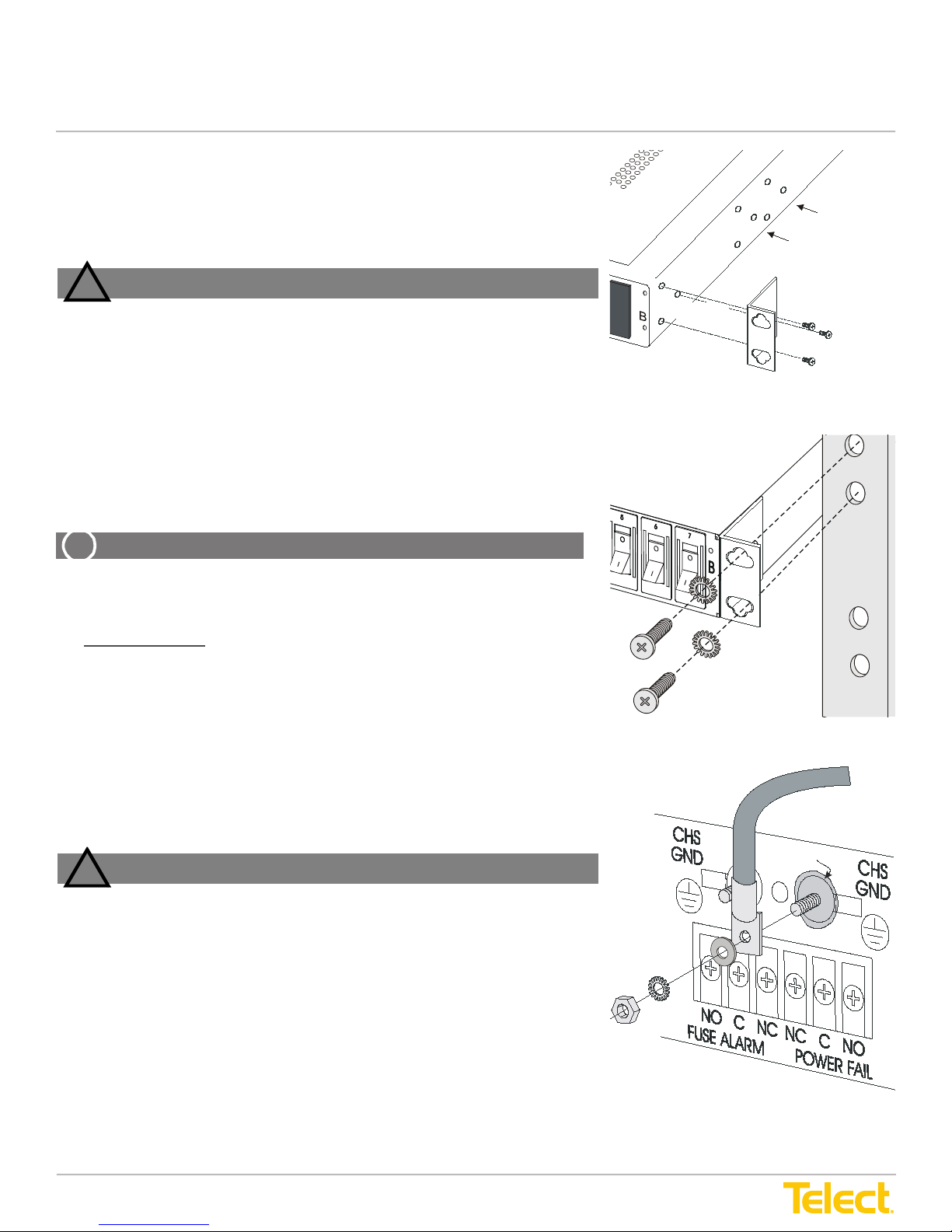
2. If necessary, remove 3 screws and reposition/re-align brackets on sides of distri-
bution panel, as shown in “Bracket Orientation”.
3. Locate an unused rack position and mount panel using 4 screws and lockwash-
ers provided, as shown in “Rack Mounting”. (Prefer mounting panel as high as
possible on rack.) Tighten screws to 35 in.-lb (4.29 N•m).
WARNING
!
WARNING! Failure to properly ground this equipment can create haz-
ardous conditions to installation personnel and to the equipment.
WARNUNG! Bei unsachgemäßer Erdung besteht Gefahr für das Instal-
lationspersonal und das Gerät!
¡AVISO! La conexión incorrecta a tierra puede ser peligrosa tanto para
los instaladores como para el equipo.
ADVERTISSEMENT ! Si vous ne reliez pas correctement cet équipe-
ment à la terre, son utilisation présente des dangers pour la personne
qui l'installe ainsi que pour l'équipement.
ALERT
!
Bracket Orientation
Torque #8 screws to
15 in.-lbs [1.7 N•m]
Mounting
Bracket
3-in. O ffset
Position
4-in. O ffset
Position
F
lush Position
4. Before connecting any conductor, use a multimeter to measure the resistance between the
input NEG and POS/RTN terminals at the rear corners of the panel. Expect 500Ω or more for
both Side A and Side B.
!
Torque #8 screws to
15 in.-lbs [1.7 N•m]
Mounting
Bracket
3-in. Offset
Position
4-in. Offset
Position
Flush Position
Torque nuts to 20 in.-lb (2.25 N•m)
Anti-oxidant
compound
Power :: T009-5XXXXXXXXXXX
Installation Guide
2. If necessary, remove three screws and reposition/realign brackets on
sides of distribution panel, as shown in “Bracket Orientation”.
3. Locate an unused rack position and mount panel using four screws and
lock washers provided, as shown in “Rack Mounting”. (Prefer mounting
panel as high as possible on rack.) Tighten screws to 35 in.-lb (4.29 N•m).
WARNING
WARNING! Failure to properly ground this equipment can create hazardous
conditions to installation personnel and to the equipment.
WARNUNG! Bei unsachgemäßer Erdung besteht Gefahr für das
Installationspersonal und das Gerät!
¡AVISO! La conexión incorrecta a tierra puede ser peligrosa tanto para los
instaladores como para el equipo.
ADVERTISSEMENT ! Si vous ne reliez pas correctement cet équipement à la
terre, son utilisation présente des dangers pour la personne qui l’installe ainsi
que pour l’équipement.
Bracket Orientation
ALERT! Only use components and crimping tools approved by agencies
or certifying bodies recognized in your country or region such as
Underwriter’s Laboratories (UL), TUV, etc.
4. For ground wiring, use a listed (approved) crimping tool to attach
a listed (approved), single- or dual-hole compression lug onto
suitable ground wire. (Use #10 to #6 AWG, depending on input
interruption device.)
5. Use a coarse, nonmetallic cleaning pad to clean terminals
and stud(s).
Rack Mounting
6. Telect recommends that you lightly coat antioxidant on lug, grounding
terminal and surrounding contacting surface. Connect lug to stud using
M5 washer and nut from terminal, as shown in “Ground Lug Connection”.
Tighten nut to 20 in.-lb (~2.25 N•m) using a 8 mm (5/16 in.) socket.
WARNING! Before connecting input power cables, make sure input
power to panel is turned off.
WARNUNG! Vor Anschluss der Eingangsstromkabel ist sicherzustellen,
dass der Eingangsstrom ausgeschaltet ist.
¡AVISO! Antes de conectar los cables de entrada de la alimentación,
compruebe que la alimentación de entrada al panel está cortada.
ADVERTISSEMENT ! Avant de connecter les câbles d’entrée d’alimentation,
assurez-vous que l’alimentation électrique du panneau est coupée.
7. Make sure input power is off.
© Telect, Inc., All Rights Reserved, 118267-3 A0
1.509.926.6000 :: telect.com
WARNING
4
Ground Lug Connection
Page 5
Dual 40/50/100A Congurable Breaker Panel
Heat shrink
tubing
BREAKER
ALARM
ALARM
RESET
INPUT
BREAKER
POWER
ON
A B BA
®
SPOKANE, WA 800-551-4567
NO C NC NC C
FUSE ALARM
NO
POWER FAIL
Power :: T009-5XXXXXXXXXXX
Installation Guide
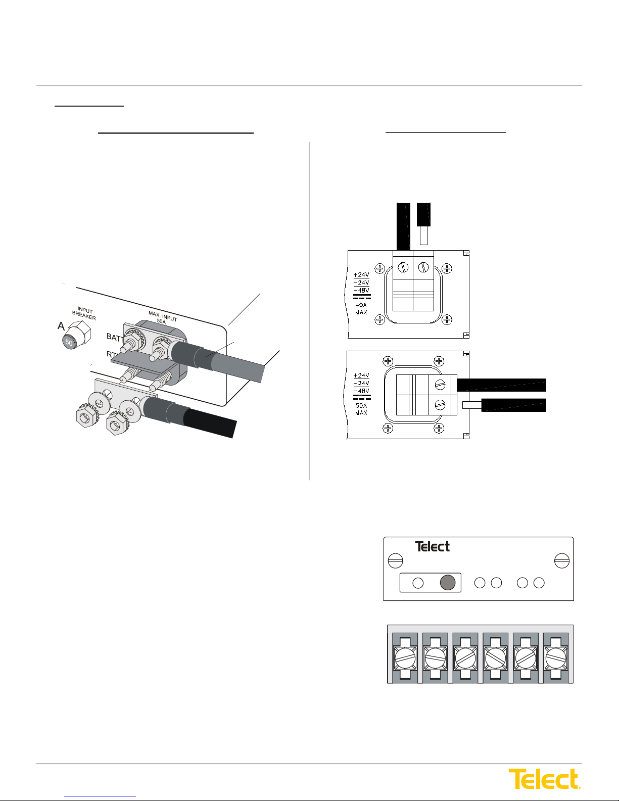
8. For input wiring — wiring used as inputs to this distribution panel — proceed as follows:
For Compression Lug Inputs
a. Crimp dual-hole compression lugs onto suitable copper
wires (#6 to #1 AWG) for BATT and RTN terminals,
Feeds A and B.
b. Remove the black plastic terminal covers, if installed.
c. Use a coarse, nonmetallic cleaning pad to clean
terminals and studs.
d. Lightly coat antioxidant on lugs, input BATTERY and
RETURN terminals, and then connect lugs to Feed A
and B input terminals on back of panel using M5 KEPs
nuts and washers provided, as shown in “Compression
Lug Inputs”. Tighten lugs to 20 in.-lb (2.25 N•m).
For Screw-Tight Inputs
a. Strip ¼ in. (0.635 cm.) of insulation from of
input cables.
b. For BATT and RTN of each feed, insert input cables
all of the way into connectors and then tighten to 14
in.-lb (~1.5 N•m).
RTN
BATT
BATT
Compression Lug Inputs Screw-Tight Vertical & Horizontal Inputs
e. Reinstall terminal covers.
9. Make sure power is off [open breaker, dummy fuse or open fuse holder at power distribution unit, or PDU] before
connecting this panel’s cables to PDU.
10. Make sure breakers on this panel are all off.
11. Enable fuse or breaker at PDU (60A or 125A max., depending on
conguration) to turn on Feed A to Side A of panel; check voltage and
polarity at input connectors of panel. Also, check:
• POWER ON A LED on front of panel turns on (green).
• INPUT BREAKER A LED (for a panel with optional input
breakers) turns on (green).
If not, check that input breakers on rear of panel are pressed in.
• BREAKER ALARM LED turns on (red).
• POWER ON B must be off.
12. With POWER ON A lit (normal operation) — but with POWER ON B LED
off (failure operation) —test power-fail relay and contacts at POWER
FAIL terminals on rear of panel:
• Expect an open circuit (∞Ω) between Terminals C and NC.
© Telect, Inc., All Rights Reserved, 118267-3 A0
1.509.926.6000 :: telect.com
• Expect continuity (0Ω) between Terminals C and NO.
RTN
Alarm Indicators
Alarm Terminals
5
Page 6
Dual 40/50/100A Congurable Breaker Panel
13. Repeat Steps 11 and 12 for Feed B and observe that POWER ON B LED turns on (green).
14. Press and hold ALARM RESET on front of panel for 5 seconds to verify that all LEDs are in working order.
15. With one or all circuit breakers off, test fuse alarm relay contacts at FUSE ALARM terminals on rear of panel:
• Expect an open circuit (∞Ω) between Terminals C and NC.
• Expect continuity (0Ω) between Terminals C and NO.
16. With both Feeds A and B on, recheck PO WER FAIL terminals:
• Expect continuity (0Ω) between Terminals C and NC.
• Expect an open circuit (∞Ω) between Terminals C and NO.
17. Recheck that all of circuit breakers on panel are off.
18. For output wiring, do either of the following:
• If using lugs, strip off
3
/8
in. (~1 cm) of insulation from one end of copper output wires and then crimp on ring or
forked, single-hole lugs, as required by NEC. (Screw terminals will accommodate lugs for up to 10 AWG.)
• If using bare wire, strip off
5
/8
in. (~1.5 cm) of insulation. (Stranded wires should be tinned.)
Remember: Output wires must be rated at or above the amperage rating of the output circuit breaker. For example,
use no smaller than #12 AWG output wiring for 20A output fuses. Do not exceed 16A continuous load for a 20A
breaker.
ALERT
!
Power :: T009-5XXXXXXXXXXX
Installation Guide
13. Repeat Steps 11 and 12 for Feed B and observe that POWER ON B LED turns on (green).
14. Press and hold ALARM RESET on front of panel for 5 seconds to verify that all LEDs are in working order.
15. With one or all circuit breakers off, test fuse alarm relay contacts at FUSE ALARM terminals on rear
of panel:
• Expect an open circuit (∞Ω) between Terminals C and NC.
• Expect continuity (0Ω) between Terminals C and NO.
16. With both Feeds A and B on, recheck POWER FAIL terminals:
• Expect continuity (0Ω) between Terminals C and NC.
• Expect an open circuit (∞Ω) between Terminals C and NO.
17. Recheck that all circuit breakers on panel are off.
18. For output wiring, do either of the following:
• If using lugs, strip off ⅜ in. (~1 cm) of insulation from one end of copper output wires and then crimp on ring
or forked, single-hole lugs, as required by NEC. (Screw terminals will accommodate lugs for up to 10 AWG.)
• If using bare wire, strip off 5/8 in. (~1.5 cm) of insulation. (Stranded wires should be tinned.)
Remember: Output wires must be rated at or above the amperage rating of the output circuit breaker. For
example, use no smaller than #12 AWG output wiring for 20A output fuses. Do not exceed 16A continuous
load for a 20A breaker.
ALERT! Local electrical and operating company guidelines recommend that the individual load not exceed 80%
of circuit breaker capacity (for example, 10A breaker x .80 = 8A max. load). Total load for all breaker outputs
on each side must not exceed —
• 40A for a panel with an optional thermal input breaker
• 50A for a panel having screw-tight inputs connectors, but without an optional thermal input breaker
• 100A for a panel having compression input connectors, but without an optional thermal input breaker
19. Clean output terminals and lugs with a nonabrasive, nonmetallic pad.
20. If installed, remove covers over output and alarm connectors.
21. Telect recommends that you lightly coat antioxidant on lugs and output BATTERY and RETURN terminals before
connecting lugs/wires to outputs. (NEC species only one lug and load for each output terminal.) Tighten screws to 9
in.-lb (1.01 N•m).
22. Connect other end of output wires to load.
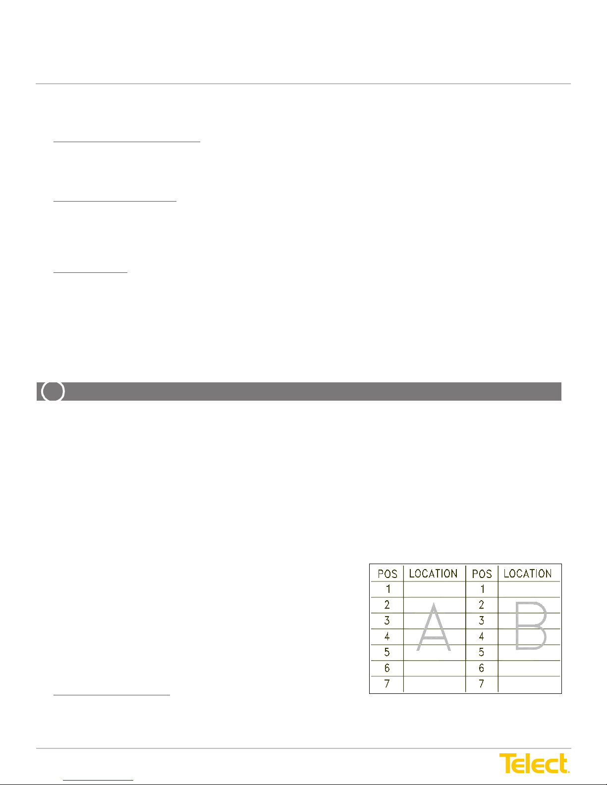
23. Use designation labels (supplied) to record outputs, as specied by
operating company standard installation procedures.
24. Make sure inputs at loads are disabled by removing all power cards or
all input fuses at load equipment.
Always follow recommended operating company guidelines when
disabling load equipment.
25. One by one, turn on circuit breakers on this panel and check voltage
and polarity at input of loads.
26. With all circuit breakers on, the BREAKER ALARM LED must go off.
Test fuse alarm relay contacts at FUSE ALARM terminals on rear of panel:
• Expect continuity (0Ω) between Terminals C and NC.
• Expect an open circuit (∞Ω) between Terminals C and NO.
© Telect, Inc., All Rights Reserved, 118267-3 A0
1.509.926.6000 :: telect.com
6
Designation Label
Page 7
Dual 40/50/100A Congurable Breaker Panel
27. Switch off one of the circuit breakers to simulate a tripped breaker.
Again, the BREAKER ALARM LED should light.
28. Press ALARM RESET on front of panel.
BREAKER ALARM LED should go off again. (Pressing ALARM RESET will reset the BREAKER ALARM LED on
front and clear FUSE ALARM on rear of panel.) Recheck FUSE ALARM terminals and expect the same status as
in Step 26 with all breakers on.
29. If desired, connect remote external audio/visual alarm indicator wires (solid or tinned wires, #30 to #16 AWG) to the
POWER FAIL and FUSE ALARM terminals.
30. One by one, re-enable load equipment and verify proper operation.
31. Re-install covers over output and alarm terminals.
REPLACING OUTPUT CIRCUIT BREAKERS
ALERT
!
O ) position.
1
/16
in. (~.15 cm) at the bottom.
Tab
Tab
Power :: T009-5XXXXXXXXXXX
Installation Guide
27. Switch off one of the circuit breakers to simulate a tripped breaker.
Again, the BREAKER ALARM LED should light.
28. Press ALARM RESET on front of panel.
BREAKER ALARM LED should go off again. (Pressing ALARM RESET will reset the BREAKER ALARM LED on
front and clear FUSE ALARM on rear of panel.) Recheck FUSE ALARM terminals and expect the same status as in
Step 26 with all breakers on.
29. If desired, connect remote external audio/visual alarm indicator wires (solid or tinned wires, #30 to #16 AWG) to the
POWER FAIL and FUSE ALARM terminals.
30. One by one, re-enable load equipment and verify proper operation.
31. Reinstall covers over output and alarm terminals.
Replacing Output Circuit Breakers
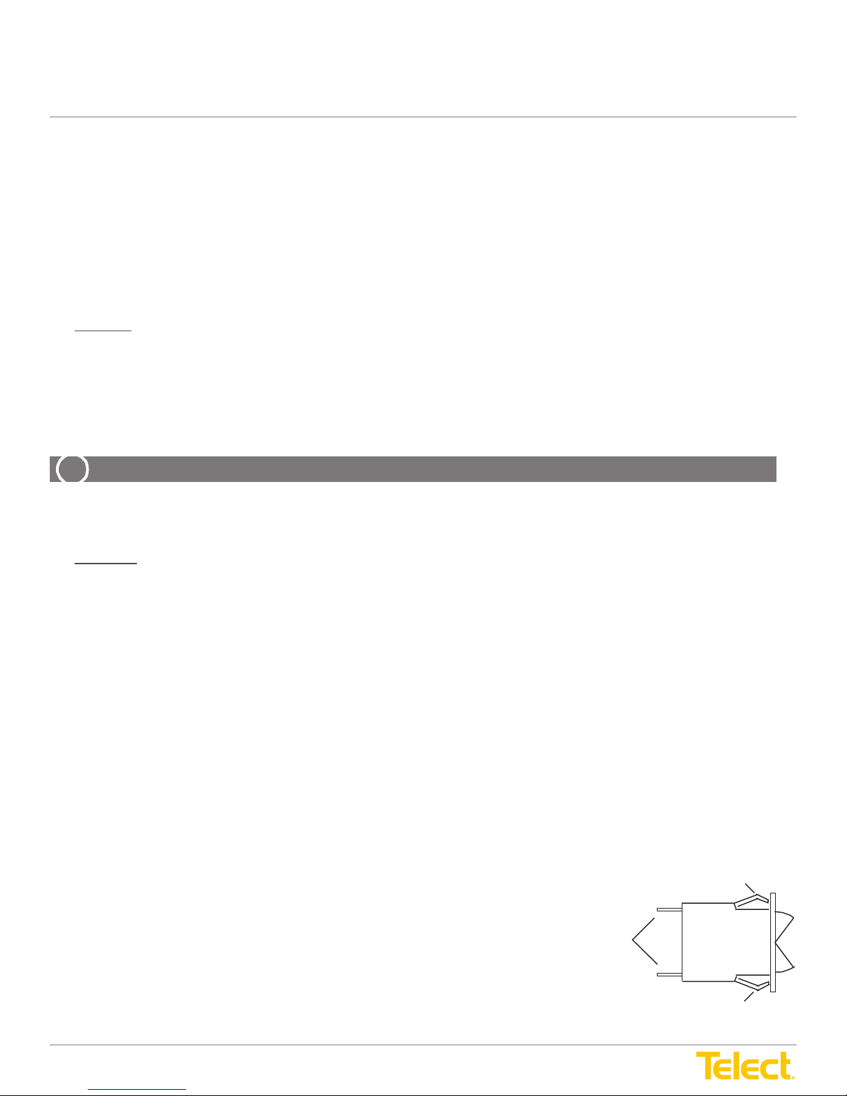
ALERT! Although difcult to remove from the panel, circuit breakers can be disconnected and replaced.
1. Be sure new breaker is the same size as breaker being replaced.
2. Place new breaker within easy reach of panel. Be sure new breaker is off ( O ) position.
3. If possible, turn off all breakers on the side (A or B) where the breaker is to be replaced. Then, turn off input power to
that side of panel.
4. Place breaker to be replaced in the off position.
5. Using a very small, at-tipped screwdriver, carefully pry out on bottom of breaker while applying upward force on face
of breaker.
This should raise the bottom of the breaker so it slightly protrudes out the front of the panel.
6. While preventing breaker from going back into panel, depress bottom tab with the screwdriver and pull out on breaker.
This starts the tab through the panel front opening so that it is dislodged about 1/16 in. (~.15 cm) at the bottom.
7. While pulling on breaker, work the screwdriver at the top to release the top tab.
If both tabs are released, the breaker should begin to pull out the front of the panel.
8. The breaker conductors can be pulled loose from the assembly at the rear of the panel. Do not pull out on the breaker
more than necessary when removing and installing the LOAD and LINE connectors.
9. Gently work breaker out front of panel until rear connectors can be accessed
by pliers.
10. Remove LOAD connector from breaker using needle-nose pliers:
• For standard circuit breaker installations, with “O” at the top and “|”
at the bottom, the LOAD connector will be near the bottom.
• For circuit breaker installations with “|” at the top and “O” at the
bottom, the LOAD connector will be near the top.
Spade
Connectors
LINE
Carlingswitch
Series M
Circuit Breaker
LOAD
11. Restrain connector to prevent it from traveling back into the panel.
© Telect, Inc., All Rights Reserved, 118267-3 A0
1.509.926.6000 :: telect.com
7
Page 8
Dual 40/50/100A Congurable Breaker Panel
ALERT
!
Power :: T009-5XXXXXXXXXXX
Installation Guide
ALERT! The LINE side connection of the breaker has live VDC. Do not allow contact of the connector (or tools
holding the connector) to grounded ironwork or panel chassis.
12. While holding breaker out from the front of the panel, grasp LINE connector of breaker with needle-nose pliers.
13. Hold the LINE connector with pliers and then pull breaker, wiggling it until breaker is free from connector. Continue to
hold the LINE connector with the pliers. Do not allow the connector to contact the panel chassis.
14. With your free hand, pick up new breaker and check orientation of new breaker.
15. Press spade connector of new breaker into the pliers-held LINE connector until fully seated.
Visually inspect the connection to be sure full contact is made between the LINE connector and the breaker
spade connector.
16. Place the LOAD conductor connector on the LOAD spade connector of the breaker. Visually inspect the connection.
17. Gently place breaker back into panel. Push on front of breaker until tabs are cleared and breaker is secure in panel.
18. If input power was turned off, restore input power and turn on breakers one at a time.
19. When new breaker is turned on, check output terminal for correct polarity.
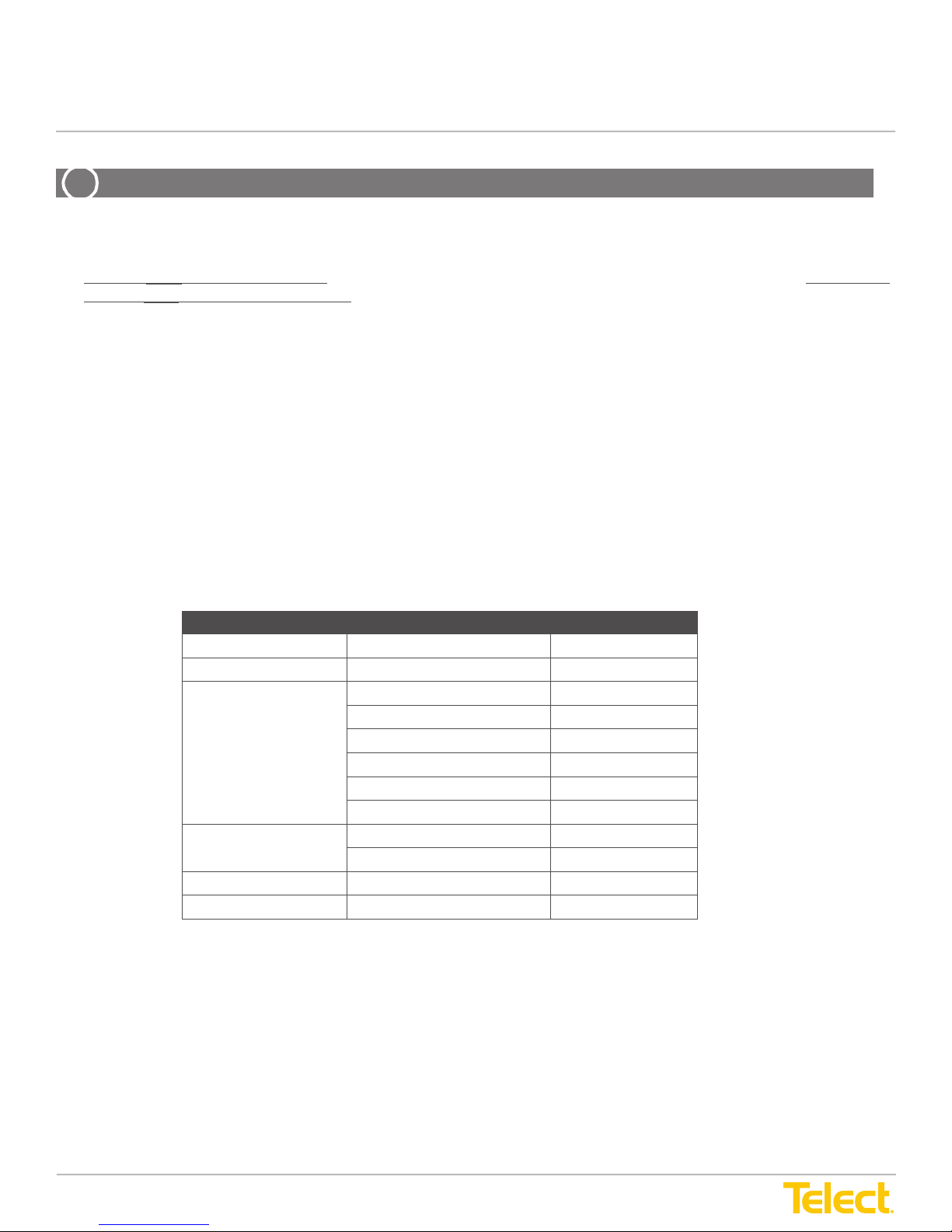
Accessories
The following lists optional and replacement items for the panel. For compression lugs, please refer to Wire Sizing, Label
Convention & Lug Chart (Telect Part No. 117995) included with your panel.
Item Description Part Number
Alarm card With INPUT BREAKER LEDs 400207
Circuit breaker
ETSI Mounting Brackets Black 090-0041-0030
Front Cover Clear 090-0001-0001
Designation Label 1-7, A & B 115353
1. Breakers are sold for repair/replacement of eld breakers and not for reconguring the panel.
1
1A long delay 115268
3A long delay 115266
5A long delay 115267
10A long delay 115269
15A long delay 115265
20A long delay 115270
Blank 113882
White 090-0041-0031
For service and warranty information see our telect.com website, email inquires to [email protected] or phone
us at 509.926.6000.
© Telect, Inc., All Rights Reserved, 118267-3 A0
1.509.926.6000 :: telect.com
8
Page 9

Dual 40/50/100A Congurable Breaker Panel
Power :: T009-5XXXXXXXXXXX
Installation Guide
LED & Alarm Summary
Normal Operation
• POWER ON A & POWER ON B LEDs will be on (green)
• INPUT BREAKER A & INPUT BREAKER B LEDs will be on (green) for panel with optional input breakers
• BREAKER ALARM LED will be off
• FUSE ALARM relay is de-energized so that —
◊ C to NC is closed and
◊ C to NO is open
• POWER FAIL relay is energized so that —
◊ C to NC is closed and
◊ C to NO is open
Input Power Failure
• POWER ON A or POWER ON B LED(s) will go off
• POWER FAIL relay de-energizes so that —
◊ C to NC opens and
◊ C to NO closes
Input Breaker Opens (input breakers are optional)
• INPUT BREAKER A or INPUT BREAKER B LED(s) will go off
• BREAKER ALARM LED will go on (red)
• POWER FAIL relay de-energizes so that —
◊ C to NC opens and
◊ C to NO closes
• FUSE ALARM relay energizes so that —
◊ C to NC opens and
◊ C to NO closes
Output Breaker Opens (either being tripped or manually turned off)
• BREAKER ALARM will go on (red)
• FUSE ALARM relay energizes so that —
◊ C to NC opens and
◊ C to NO closes
Pressing ALARM RESET turns off BREAKER ALARM LED and de-energizes FUSE ALARM relay.
© Telect, Inc., All Rights Reserved, 118267-3 A0
1.509.926.6000 :: telect.com
9
Page 10
Dual 40/50/100A Congurable Breaker Panel
Power :: T009-5XXXXXXXXXXX
Installation Guide
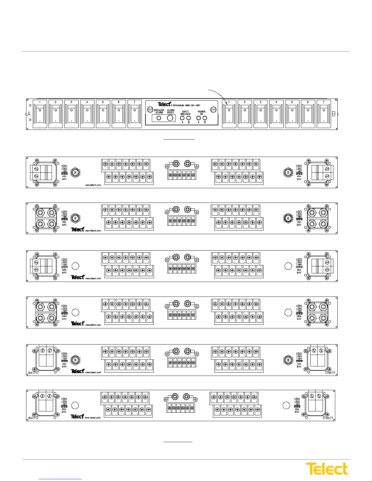
Physical Attributes
B-Side Inputs
Breaker Positions A1 - A7 Breaker Positions B1 - B7
O at Top and | at Bottom
FRONT VIEW
Wire Binding B-Side Inputs Wire Binding A-Side Inputs
Breakers Shown with
BATT
RTN
INPUT
BREAKER
1
BATT
B
RTN
1
CHS
7
GND
CHS
GND
1
7
BATT
A
C
CNO
NCNC
7
FUSE ALARM
POWER FAIL
NO
1
RTN
7
Screw-Tight Horizontal Inputs With 50A Input Breakers
BATT
RTN
INPUT
BREAKER
BATT
1
CHS
7
GND
B
RTN
1
NO
7
FUSE ALARM
NCC NOCNC
POWER FAIL
CHS
GND
1
7
BATT
A
RTN
1
7
Compression Inputs With 50A Input Breakers
BATT
RTN
INPUT
BREAKER
1
BATT
B
RTN
1
CHS
7
GND
CHS
GND
1
7
BATT
A
FUSE ALARM
NCCNO CNC
POWER FAIL
1
7
NO
RTN
7
INPUT
BREAKER
INPUT
BREAKER
INPUT
BREAKER
A-Side Inputs
BATT
RTN
BATT
RTN
BATT
RTN
Screw-Tight Horizontal Inputs Without 50A Input Breakers
BATT
INPUT
BREAKER
BATT
1
B
RTN
RTN
1
Compression Inputs Without 50A Input Breakers (100A max./side)
INPUT
BREAKER
BATT
1
B
RTN
RTN
1
Screw-Tight Vertical Inputs With 50A Input Breakers
INPUT
BREAKER
BATT
1
B
RTN
RTN
1
Screw-Tight Vertical Inputs Without 50A Input Breakers
© Telect, Inc., All Rights Reserved, 118267-3 A0
1.509.926.6000 :: telect.com
7
7
7
7
7
7
CHS
GND
NCCNO CNC
FUSE ALARM
POWER FAIL
CHS
GND
NO
NCNCC
POWER FAILFUSE ALARM
CHS
GND
CNCNC
CNO
FUSE ALARM
POWER FAIL
REAR VIEW
10
CHS
GND
1
7
BATT
INPUT
BREAKER
BATT
A
7
BATT
RTN
7
INPUT
BREAKER
RTN
NO
CHS
GND
1
1
A
7
BATT
RTN
7
INPUT
BREAKER
RTN
NOC
CHS
GND
1
1
A
NO
1
RTN
7
RTN
Page 11
Dual 40/50/100A Congurable Breaker Panel
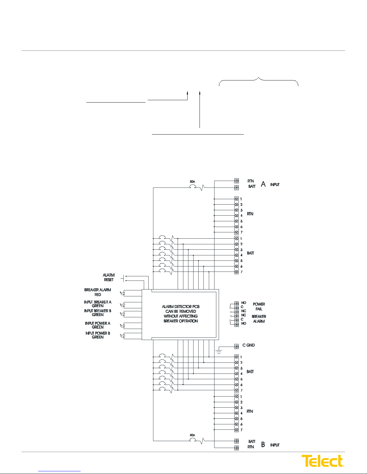
(Shown in alarm state)
(Optional)
(Optional)
Power :: T009-5XXXXXXXXXXX
Installation Guide
Conguration
Breaker Positions Per Side
0=Black Enclosure/Standard Breaker Installation with Off (O) at Top
1=White Enclosure/Standard Breakers Installation with Off (O) at Top
2=Black Enclosure/Breakers Installed with On (|) at Top
3=White Enclosure/Breakers installed with On (|) at Top
Schematic Drawing
Panel Color/Breaker Orientation
T009-5 X X 0 X X X X X X X
Inputs (Type of Connector & Input Circuit Breaker)
0=Screw-Tight Horizontal Inputs with 50A Thermal Input Breakers
1=Compression Inputs with 50A Thermal Input Breakers
2=Screw-Tight Horizontal Inputs without Input Breakers
3=Compression Inputs without Input Breakers (100A max./side)
4=Screw-Tight Vertical Inputs with 50A Thermal Input Breakers
5=Screw-Tight Vertical Inputs without Input Breakers
0=Blank
1=1A
3=3A
5=5A
A=10A
F=15A
K=20A
© Telect, Inc., All Rights Reserved, 118267-3 A0
1.509.926.6000 :: telect.com
11
Page 12
Dual 40/50/100A Congurable Breaker Panel
INPUT
BREAKER
B
BATT
-24V
-48V
100A
MAX
+24V
RTN
BATT
RTN
GND
CHS CHS
GND
INPUT
BREAKER
-24V
RTN
-48V
100A
MAX
+24V
BATT
INPUT
BREAKER
+24V
MAX
RTN
40A
-48V
-24V
BATT
RTN
0.31 [.79]0.18 [.45]
MAX
-48V
-24V
+24V
INPUT
BREAKER
www.telect.com
9.48 [24.1]
[24.1]
[20.4]
[10.2]
M5 Studs
[4.32]
[3.17]
1.70
1.25
23.00 [58.4]
22.31 [56.7]
18.31 [46.5]
8.05
4.00
17.25 [43.8]
9.48
0.63 [1.59]
9.71 [24.66]
Power :: T009-5XXXXXXXXXXX
Installation Guide
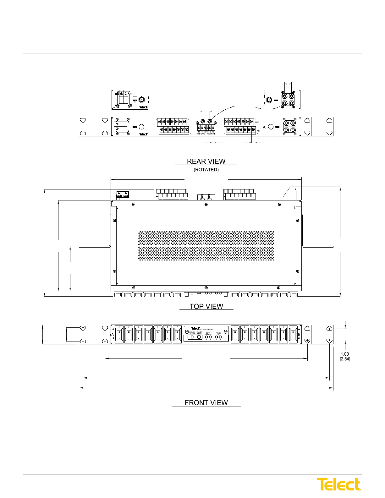
Assembly Drawing
Telect assumes no liability from the application or use of these products. Neither does Telect convey any license under
its patent rights or the patent rights of others. This document and the products described herein are subject to change
without notice.
© Telect, Inc., All Rights Reserved, 118267-3 A0
1.509.926.6000 :: telect.com
12
 Loading...