

Page 1
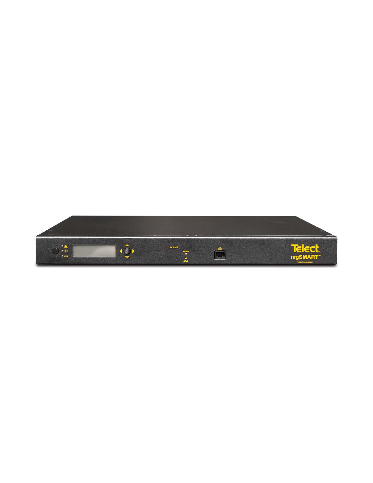
nrgSMART
™
™
Controller
nrgSMART
Confi guration Guide
nrgOS 3.1.1
Controller
nrgCONTROL-BT
Page 2
nrgSMART
nrgSMART
™
Controller Confi guration Guide
POWER ::
User Guide
™
Controller Confi guration Guide
POWER ::
User Guide
Table of Contents
1. Introduction ......................................................................................................................6
1.1 Connect Controller ..................................................................................................6
1.2 Confi guration Wizard Display ..................................................................................7
1.3 About this Guide ......................................................................................................8
2. Controller Tab ..................................................................................................................8
2.1 Term Interpretation ..................................................................................................8
2.2 Controller Tab Settings ............................................................................................9
2.3 Firmware Upgrade Procedure ...............................................................................19
3. Site Tab Settings ............................................................................................................25
4. Panels Tab Settings .......................................................................................................28
5. Equipment Tab Settings .................................................................................................52
5.1 Importing CSV and Adding Equipment .................................................................56
6. Supplementary Information ............................................................................................65
6.1 MIB Table .................................................................................................................65
6.2 Fuse/Circuit Breaker Ratings ...................................................................................65
6.3 GMT Fuses ..............................................................................................................68
© Telect, Inc. All rights reserved. 3.22.17 v.3
1.509.926.6000 :: telect.com
2
Page 3
nrgSMART
nrgSMART
™
Controller Confi guration Guide
POWER ::
User Guide
™
Controller Confi guration Guide
POWER ::
User Guide
List of Figures
Figure 1 - nrgBDFB Connections ..........................................................................................4
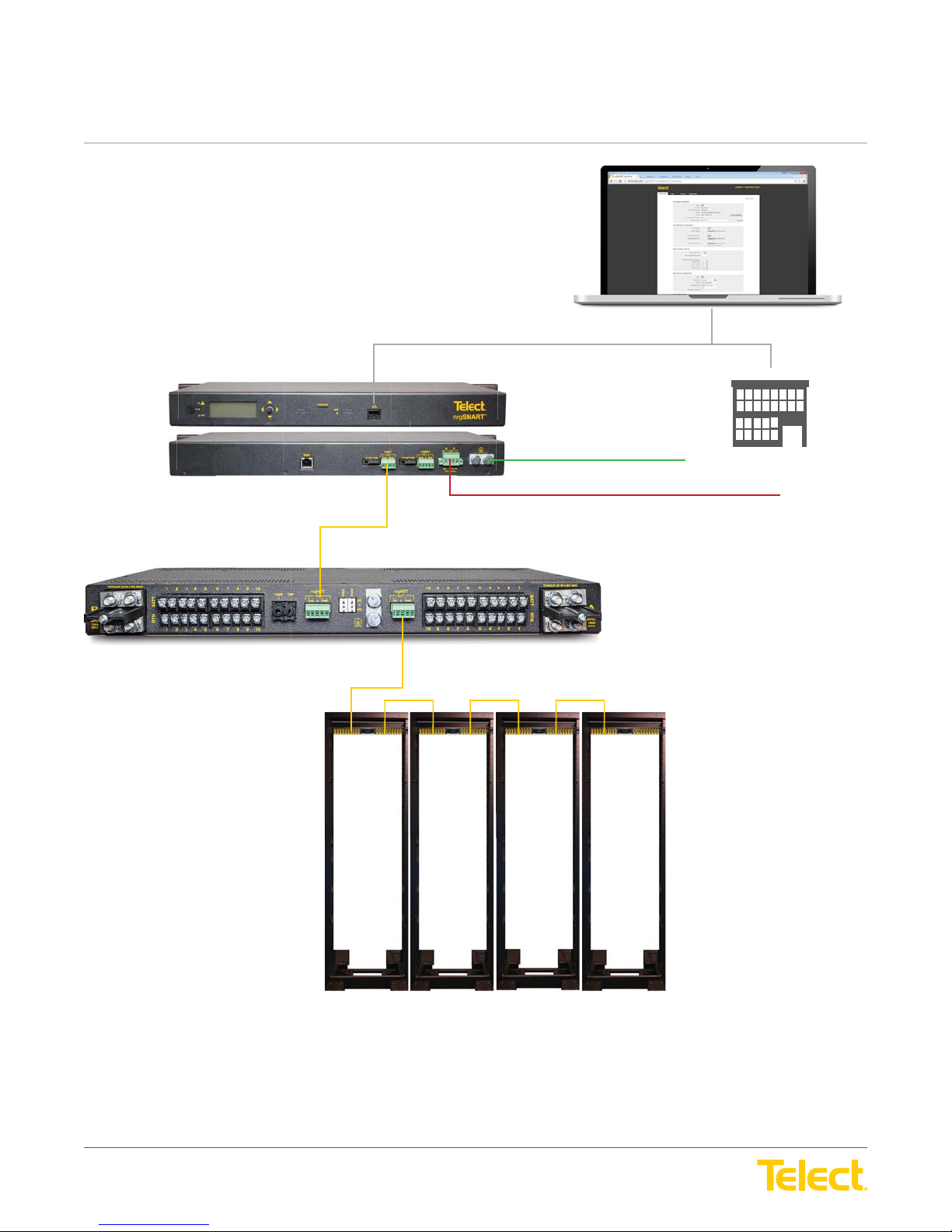
Figure 2 - nrgSMART™ Distributed Network Monitoring and Connections ..........................5
Figure 3 - nrgSMART Controller to PC Connection ..............................................................6
Figure 4 - Connection Successful - nrgSMART Confi guration Wizard Opens ......................6
Figure 5 - Controller Tab .......................................................................................................7
Figure 6 - Site Tab ................................................................................................................7
Figure 7 - Panels Tab ............................................................................................................7
Figure 8 - Equipment Tab .....................................................................................................7
Figure 9 - Controller Tab Window .........................................................................................9
Figure 10 - Controller Information Screen ..........................................................................11
Figure 11 - Controller Information - More info/Less info Screen .........................................12
Figure 12 - Save/Restore Confi guration Screen .................................................................14
Figure 13 - Measurement Settings Screen .........................................................................15
Figure 14 - LAN Confi guration Screen ................................................................................16
Figure 15 - SNMP Screen ...................................................................................................18
Figure 16 - Site Tab Window ...............................................................................................25
Figure 17 - Site Information Screen ....................................................................................26
Figure 18 - Panels Tab Window ..........................................................................................28
Figure 19 - BDFB and Panels Screen ................................................................................30
Figure 20 - Sort Order Screen ............................................................................................31
Figure 21 - Panel Information Screen .................................................................................32
Figure 22 - Quad System ....................................................................................................35
Figure 23 - Dual System .....................................................................................................37
Figure 24 - Panel Information More info/Less info Screen .................................................38
Figure 25 - Circuit Confi guration Screen ............................................................................39
Figure 26 - Circuit Settings Window ...................................................................................41
Figure 27 - Panels Settings Screen ....................................................................................42
Figure 28 - Feed Alarms Screen .........................................................................................43
Figure 29 - Voltage Sensors Screen and Temperature Sensors Screen ............................46
Figure 30 - Current Sensors Screen ...................................................................................48
Figure 31 - Equipment Tab Window ....................................................................................52
Figure 32 - Equipment Models, Add Equipment and Equipment ........................................53
Figure 33 - New Equipment Information Window/Equipment Information Screen ..............54
Figure 34 - Equipment Power Source Screen ....................................................................63
Figure 35 - Equipment Power Summary Screen ................................................................64
© Telect, Inc. All rights reserved. 3.22.17 v.3
1.509.926.6000 :: telect.com
3
Page 4
nrgSMART
nrgSMART
™
Controller Confi guration Guide
POWER ::
User Guide
™
Controller Confi guration Guide
POWER ::
User Guide
Site Controller
Chassis Ground
Local LAN
Connection
SNMP
nrg600BT08-M
nrgNET IN
nrgNET IN
nrgNET OUT
nrgNET OUT
Left Daisy
Chain
Configuration
nrgNET IN
nrgNET IN
Right Daisy
Chain
Configuration
nrgBDFB
nrg100GMT10-M
nrgNET OUT
nrgNET OUT
The nrgBDFB has a built-in controller that has a LAN connection port and nrgNET outputs that connect to 22 external nrgSMART panels and
up to eight internal nrgBDP panels.
© Telect, Inc. All rights reserved. 3.22.17 v.3
1.509.926.6000 :: telect.com
Figure 1 - nrgBDFB Connections
4
Page 5
nrgSMART
nrgSMART
™
Controller Confi guration Guide
POWER ::
User Guide
™
Controller Confi guration Guide
POWER ::
nrgCONTROL-BT
nrg100GMT10-M-BT
User Guide
Local LAN Connection
SNMP
Chassis Ground
DC Power
Connection
nrgNET Out
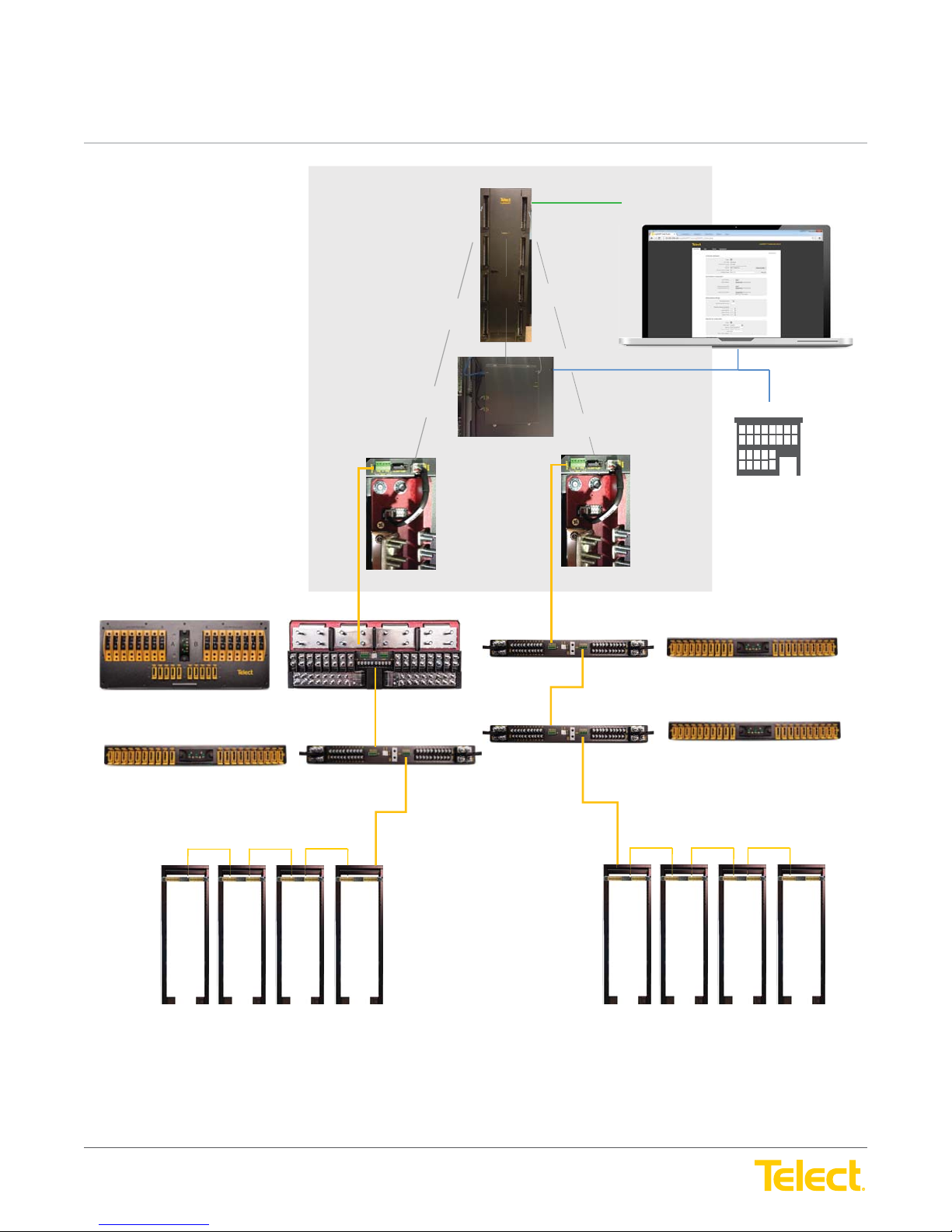
Figure 2 - nrgSMART™ Distributed Network Monitoring and Connections
The nrgCONTROL-BT connects to the local LAN connection port and nrgNET outputs connect to 30 external nrgSMART panels.
© Telect, Inc. All rights reserved. 3.22.17 v.3
1.509.926.6000 :: telect.com
5
Page 6
nrgSMART
nrgSMART
™
Controller Confi guration Guide
POWER ::
User Guide
™
Controller Confi guration Guide
POWER ::
User Guide
1. Introduction
Controller confi guration software sets the structure of nrgSMART’s system operation. It confi gures various parameters that defi ne site labels,
panel labels and circuit specifi c labels, thresholds and behaviors which instruct the controller to implement measures that facilitate equipment
operation, monitoring and control.
1.1 Connect Controller
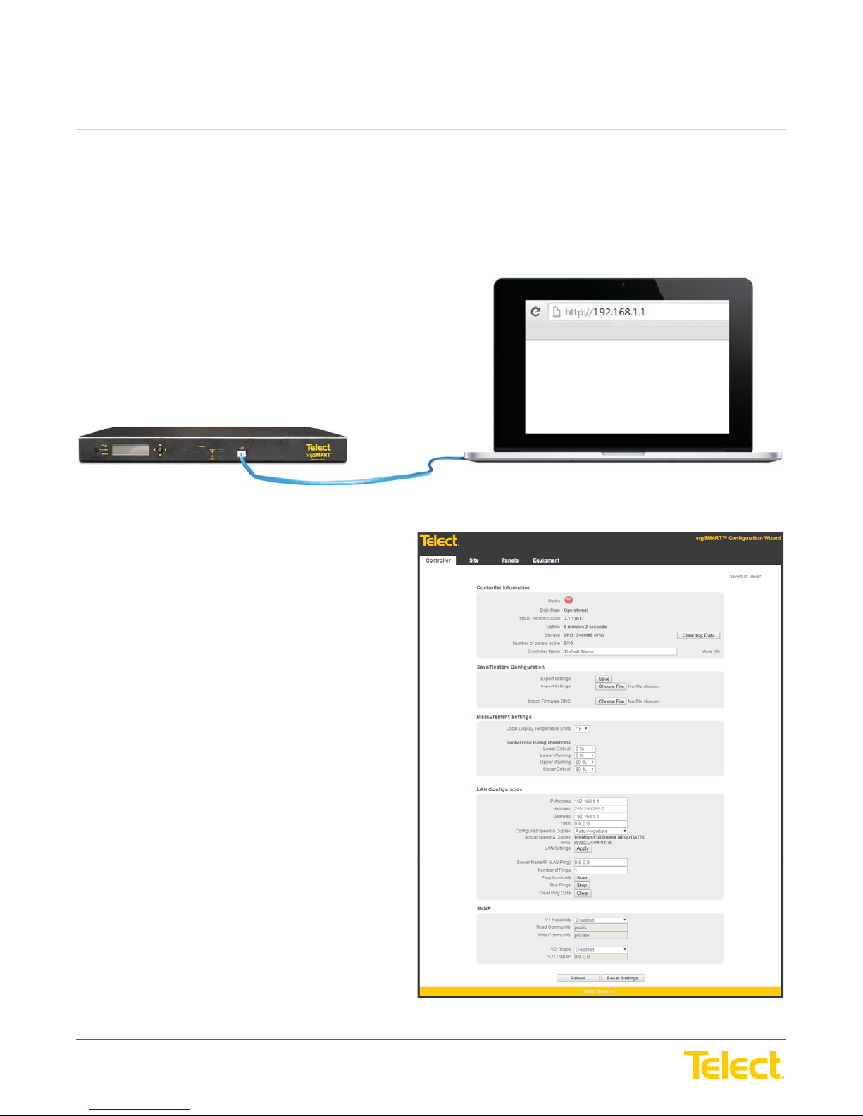
Figure 3 - nrgSMART Controller to PC Connection
To hook up the controller to a laptop or desktop computer:
1. Apply power to the computer and controller.
2. Attach Ethernet cable into the port on the PC.
3. Attach the other end of the Ethernet cable into the LAN port
on the front of the controller. (See Figure 3)
4. Open your internet browser.
• Browsers supported include:
* Chrome (recommended)
* Firefox
5. In the URL fi eld enter http://192.168.1.1 and press return.
The controller is now connected and the nrgSMART
Confi guration Guide will open. (See Figure 4)
© Telect, Inc. All rights reserved. 3.22.17 v.3
1.509.926.6000 :: telect.com
Figure 4 - Connection Successful -
nrgSMART Confi guration Wizard Opens
6
Page 7
nrgSMART
nrgSMART
™
Controller Confi guration Guide
POWER ::
User Guide
™
Controller Confi guration Guide
POWER ::
User Guide
1.2 Confi guration Wizard Display
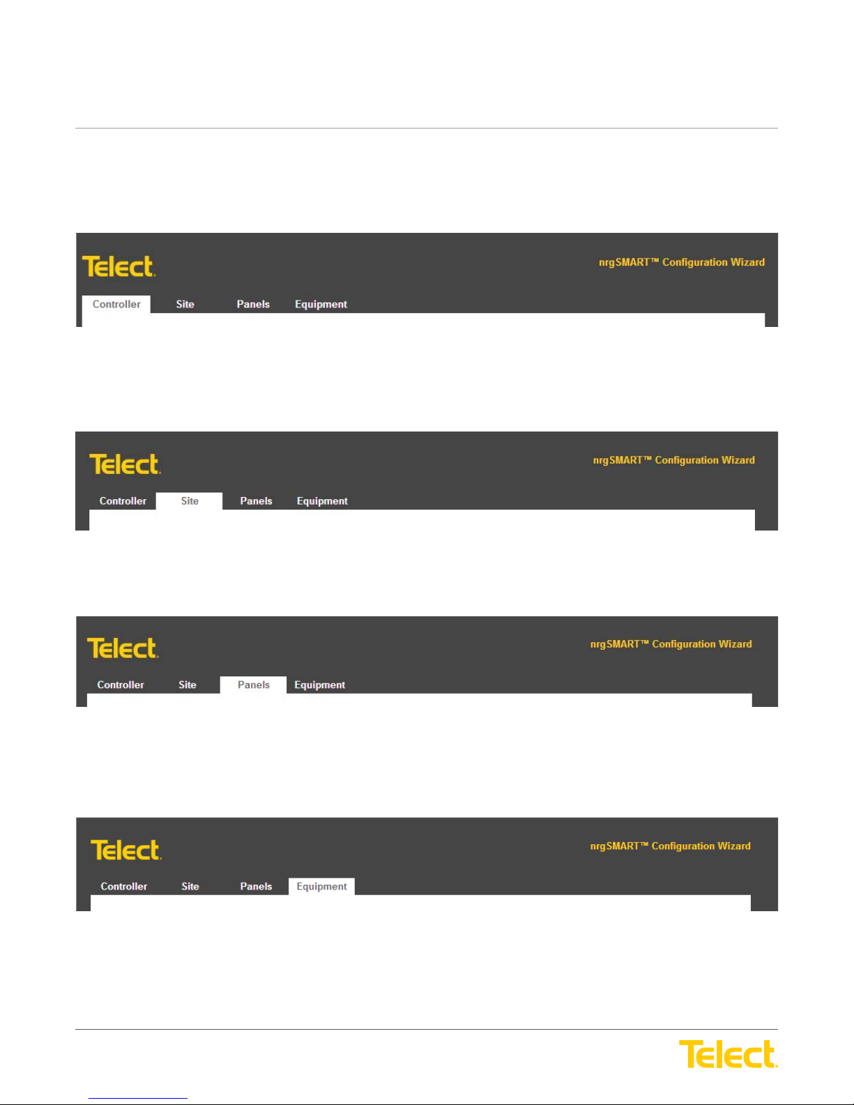
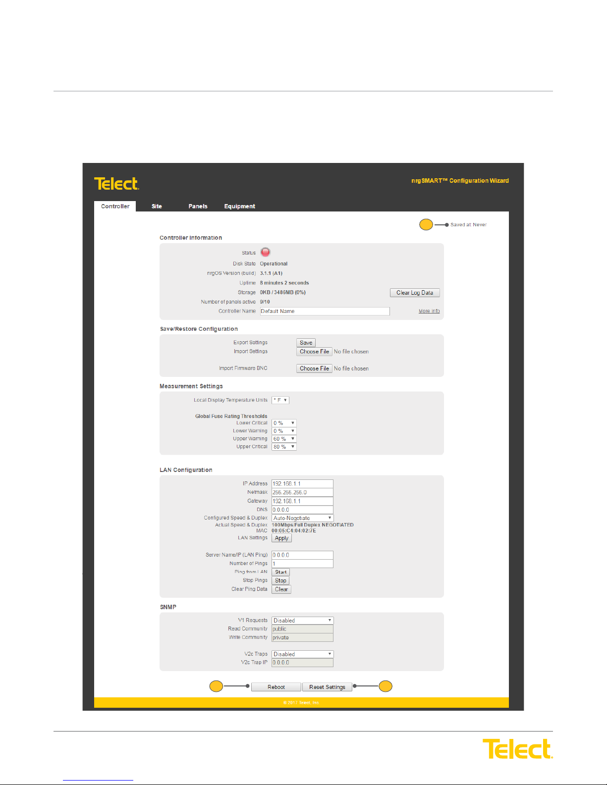
When connected to the nrgSMART Confi guration Wizard, four tabs—Controller, Site, Panels and Equipment—display at the top of the window.
Each tab contains confi guration screens where associated fi eld values can be defi ned or viewed.
Figure 5 - Controller Tab
Controller Tab: View or modify controller information in the
Restore Confi guration, Measurement Settings, LAN Confi guration and SNMP.
Controller Tab Window
and in the following screens:
Controller Information, Save/
Figure 6 - Site Tab
Site Tab: View or modify site specifi c information in the
Panels Tab: View or modify panel information in the
Information, Circuit Confi guration, Advanced (Panel Settings, Feed Alarms, Voltage Sensors, Temperature Sensors
Site Tab Window
Figure 7 - Panels Tab
Panels Tab Window
Figure 8 - Equipment Tab
and in the
and in the following screens/windows:
Site Information Screen
.
Panels, Sort Order, Panel
and
Current Sensors)
.
Equipment Tab: View or modify equipment information in the
Equipment Models, Equipment Information, Equipment Power Source
© Telect, Inc. All rights reserved. 3.22.17 v.3
1.509.926.6000 :: telect.com
Equipment Tab Window
and
Equipment Power Summary
7
and in the following screens:
.
Equipment,
Page 8
nrgSMART
nrgSMART
™
Controller Confi guration Guide
POWER ::
User Guide
™
Controller Confi guration Guide
POWER ::
User Guide
1.3 About this Guide
This guide provides guidelines to assist in the confi guration of the nrgSMART Controller. While care has been taken to defi ne all associated
components of this product, every aspect of controller confi guration may not be covered.
Throughout this guide, Notes, Alerts, Cautions, Warnings and Danger notifi cations may be used to convey important information the user
should pay special attention to.
2. Controller Tab
Controller Tab
The
equipment. From this tab, measurement threshold settings are set, local networks defi ned and monitoring options designated.
2.1 Term Interpretation
Simple Network Management Protocol (SNMP)
SNMP is a way to monitor network devices that are on an IP network. Information is requested by the SNMP Manager and received from a
network device, about the device and connected equipment, and is sent and stored in a Management Information Base (MIB). With baseline
measurements and continuous updates, equipment performance can be tracked and controlled. Additionally, the SNMP Traps protocol sends
alerts instantly whenever an event occurs.
allows the user to view information and defi ne how the controller communicates with the site, the panels and the
The SNMP Manager uses Simple Network Management Protocol (SNMP) that interacts with a network device and its connected equipment.
Through the Local Area Network (LAN), the SNMP Manager routinely requests information, such as power provisioning, remote site
management and circuit threshold data from network devices in different locations. This information is recorded and stored at a central
Management Information Base (MIB) and can be viewed in a user friendly table. Content displays equipment type and location, performance
and power usage, and monitors threshold levels which can anticipate problems with equipment, mitigating downtime so that maintenance can
be scheduled on a routine basis.
SNMP Traps send instant alerts from the network device when an unusual event occurs. The network device sends these messages without
receiving a request from the SNMP Manager; they are not recorded in the MIB. As soon as an event occurs an alarm is triggered indicating
where the event is. Immediate access to equipment alarms can prevent unnecessary downtime. During an event, an alarm promptly notifi es
the local technician who can then make repairs or prevent equipment damage.
© Telect, Inc. All rights reserved. 3.22.17 v.3
1.509.926.6000 :: telect.com
8
Page 9
nrgSMART
nrgSMART
™
Controller Confi guration Guide
POWER ::
User Guide
™
Controller Confi guration Guide
POWER ::
User Guide
2.2 Controller Tab Settings
Controller Tab
The
values which are pre-defi ned. The
allow other controller related settings to be defi ned or viewed.
is comprised of the main window (
Controller Tab Window
Controller Tab Window
contains Reboot and Reset Settings buttons. Within the window are screens that
) and screens that allow custom settings or display read only
1
© Telect, Inc. All rights reserved. 3.22.17 v.3
1.509.926.6000 :: telect.com
2
Figure 9 - Controller Tab Window
9
3
Page 10
nrgSMART
nrgSMART
™
Controller Confi guration Guide
POWER ::
User Guide
™
Controller Confi guration Guide
POWER ::
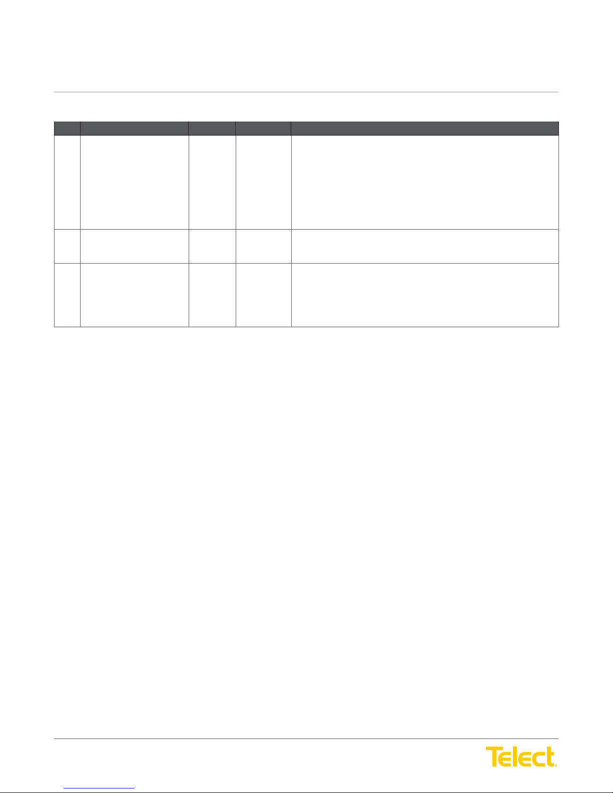
Controller Tab Window
Ref. Field Type Value Description
1 Saved At Read Only Text The date and time that information in the
2 Reboot Select Button Reboots the controller and retains settings.
3 Reset Settings Select Button Resets the controller.
User Guide
NOTE: When a fi eld is updated within a window or screen in the
Controller Tab, clicking outside of the fi eld saves the information and
updates the Saved At time.
Field settings are:
Never: Data not saved
Date/Time: mm/dd/yyyy HH:MM:SS (AM/PM)
Select the Reboot button to reboot the controller.
Select Reset Settings button to reset the controller.
NOTE: Reset settings sets the controller back to factory default including
the IP address.
Controller Tab
was last saved.
© Telect, Inc. All rights reserved. 3.22.17 v.3
1.509.926.6000 :: telect.com
10
Page 11
nrgSMART
nrgSMART
™
Controller Confi guration Guide
POWER ::
User Guide
™
Controller Confi guration Guide
POWER ::
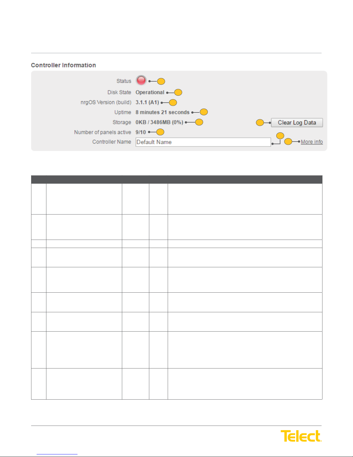
Controller Tab :: Controller Information Screen
Ref. Field Type Value Description
1 Status Read Only Light Light color varies to show the panel of the attached panels.
2 Disk State Read Only Text Micro SD card performance.
User Guide
1
2
3
4
5
7
Figure 10 - Controller Information Screen
Green: No alarms present.
Red: One or more alarms present on attached panels, or a panel
is missing.
6
8
9
Operational: Micro SD card operating normally.
Bad Disk: Micro SD not functioning or is not installed.
3 nrgOS Version (Build) Read Only Text Latest nrgSMART Operating System version.
4 Uptime Read Only Text How long the controller has been operating without interruption or reboot.
Displays as: Days / Hours / Minutes / Seconds
5 Storage Read Only Text Amount of storage space.
Displays as: Storage space in use / Storage space remaining
(Percentage of space left)
6 Clear Log Data Select Button Clears logged data.
Select the Clear Log Data button to remove all data from the log.
7 Number of Panels Active Read Only Text The number of panels in use and how many panels are available.
Displays as: Number of panels active / Number of panels confi gured
8 Controller Name Input Text Name used to distinguish this controller from another controller within
the network.
Enter the Controller Name. This fi eld accepts up to 40 characters. Valid
characters are upper/lowercase letters, numbers, controller version
and spaces.
9 More Info/Less Info Select Toggle View more or fewer screen fi elds.
Toggle More info to expand the screen and display additional fi elds or
Less info to hide a portion of the screen.
© Telect, Inc. All rights reserved. 3.22.17 v.3
1.509.926.6000 :: telect.com
11
Page 12
nrgSMART
nrgSMART
™
Controller Confi guration Guide
POWER ::
User Guide
™
Controller Confi guration Guide
POWER ::
User Guide
10
11
12
13
14
15
16
17
18
19
20
21
22
23
24
25
26
27
28
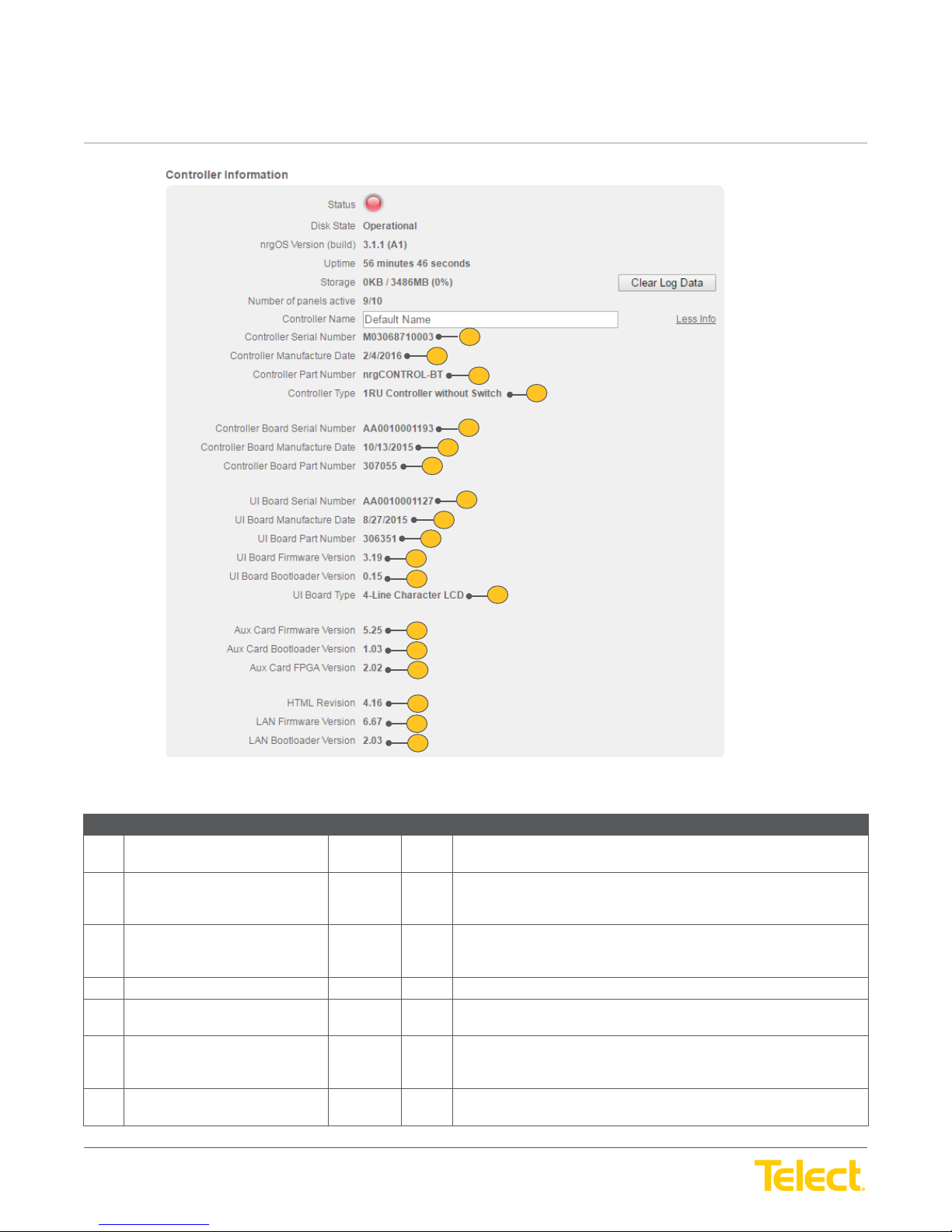
Figure 11 - Controller Information - More info/Less info Screen
Controller Tab :: Controller Information Screen
Ref. Field Type Value Description
10 Controller Serial Number Read Only Text A 12-digit serial number mounted on the controller consisting of
uppercase letters and numbers.
11 Controller Manufacturer Date Read Only Text The date the controller was manufactured.
Displays as: mm/dd/yyyy
12 Controller Part Number Read Only Text A string of characters that identify the controller as a part consisting of 18
upper/lowercase letters, numbers and symbols. Part numbers that are
longer than 18 characters will be truncated.
13 Controller Type Read Only Text Describes the type of controller installed.
14 Controller Board Serial Number Read Only Text A 12-digit serial number mounted on the Controller Board consisting of
uppercase letters and numbers.
15 Controller Board Manufacturer
Date
16 Controller Board Part Number Read Only Text A string of characters that identify the Controller Board as a part
Read Only Text The date the Controller Board was manufactured.
Displays as: mm/dd/yyyy
consisting of numbers.
© Telect, Inc. All rights reserved. 3.22.17 v.3
1.509.926.6000 :: telect.com
12
Page 13
nrgSMART
nrgSMART
™
Controller Confi guration Guide
POWER ::
User Guide
™
Controller Confi guration Guide
POWER ::
Controller Tab :: Controller Information Screen
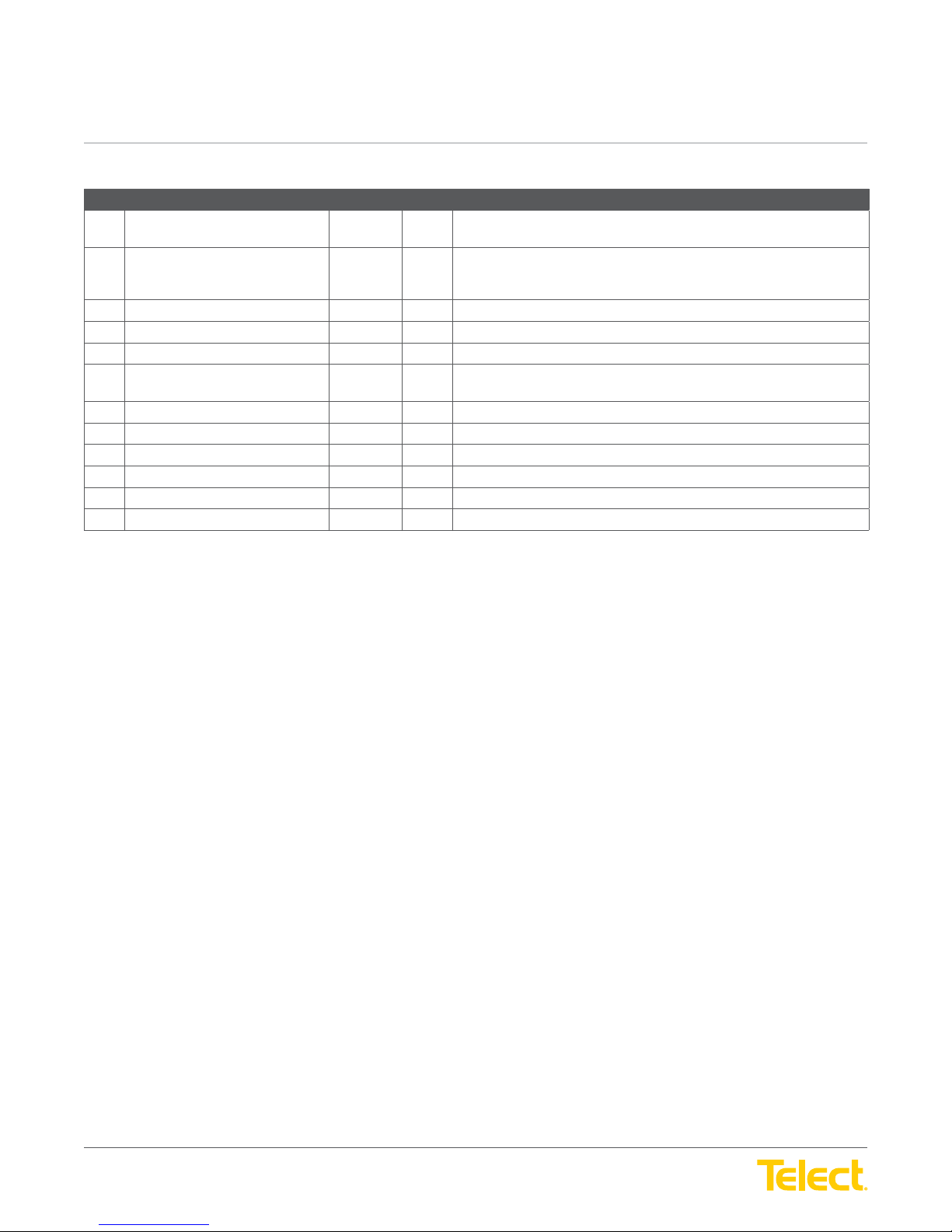
Ref. Field Type Value Description
17 UI Board Serial Number Read Only Text A 12-digit serial number mounted on the User Interface Board consisting
18 UI Board Manufacturer Date Read Only Text The date the controller was manufactured.
19 UI Board Part Number Read Only Text A six-digit number that identifi es the User Interface Board as a part.
20 UI Board Firmware Version Read Only Text The fi rmware version for the User Interface Board on the controller.
21 UI Board Bootloader Version Read Only Text The bootloader version for the User Interface Board on the controller.
22 UI Board Type Read Only Text Indicates the type of User Interface on the controller consisting of upper/
23 Aux. Card Firmware Version Read Only Text The fi rmware version for the Aux. card in use by the controller.
24 Aux. Card Bootloader Version Read Only Text The bootloader version for the Aux. card in use by the controller.
25 Aux. Card FPGA Version Read Only Text The FPGA version for the Aux. card in use by the controller.
26 HTML Revision Read Only Text The HTML revision in use.
27 LAN Firmware Version Read Only Text The fi rmware version for the Local Area Network in use by the controller.
28 LAN Bootloader Version Read Only Text The bootloader version of the Local Area Network in use by the controller.
User Guide
of uppercase letters and numbers.
Displays as: mm/dd/yyyy
lowercase letters, numbers, symbols and spaces.
© Telect, Inc. All rights reserved. 3.22.17 v.3
1.509.926.6000 :: telect.com
13
Page 14
nrgSMART
nrgSMART
™
Controller Confi guration Guide
POWER ::
User Guide
™
Controller Confi guration Guide
POWER ::
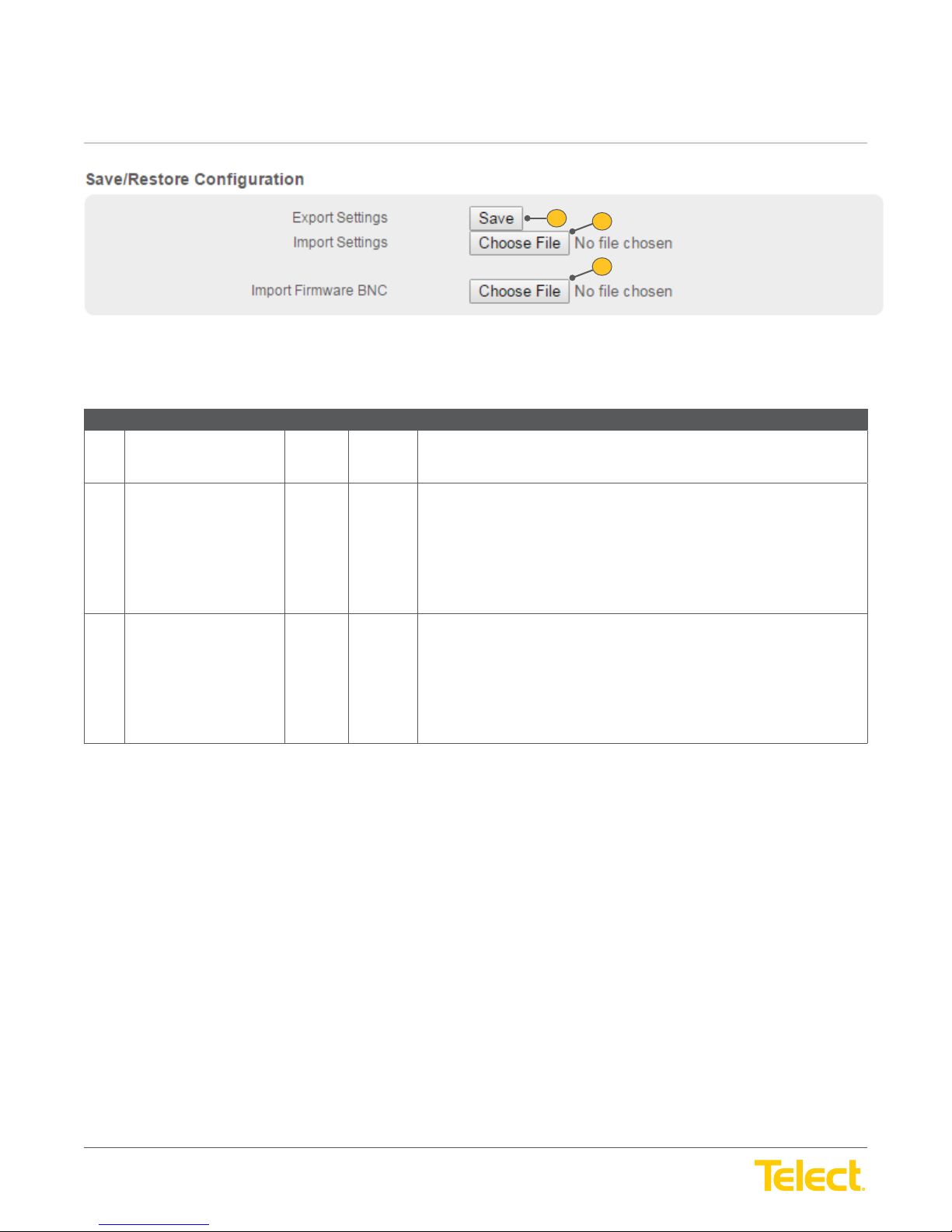
Controller Tab :: Save/Restore Confi guration Screen
Ref. Field Type Value Description
1 Export Settings Select Button Exports confi guration settings as a backup and saves them for later use.
2 Import Settings Select Button Imports confi guration settings for the controller and panel.
User Guide
1
2
3
Figure 12 - Save/Restore Confi guration Screen
Select the Save button to save controller and panel confi guration settings.
Select the Choose File button to browse for a fi le.
Locate and select the desired .ncs fi le.
Select Open to import confi guration settings.
NOTE: The selected fi le name will appear next to the Choose File button.
Requires reboot.
3 Import Firmware BNC Select Button Imports fi rmware BNC.
Select the Choose File button to browse for a fi le.
Locate and select the desired fi le.
Select Open to import the fi le.
NOTE: Once a fi le has been added it will appear below the Choose File button.
Requires reboot.
Telect recommends backing up your settings once the controller is confi gured. This will make sure your settings are saved during future
fi rmware updates or changes.
© Telect, Inc. All rights reserved. 3.22.17 v.3
1.509.926.6000 :: telect.com
14
Page 15
nrgSMART
nrgSMART
™
Controller Confi guration Guide
POWER ::
User Guide
™
Controller Confi guration Guide
POWER ::
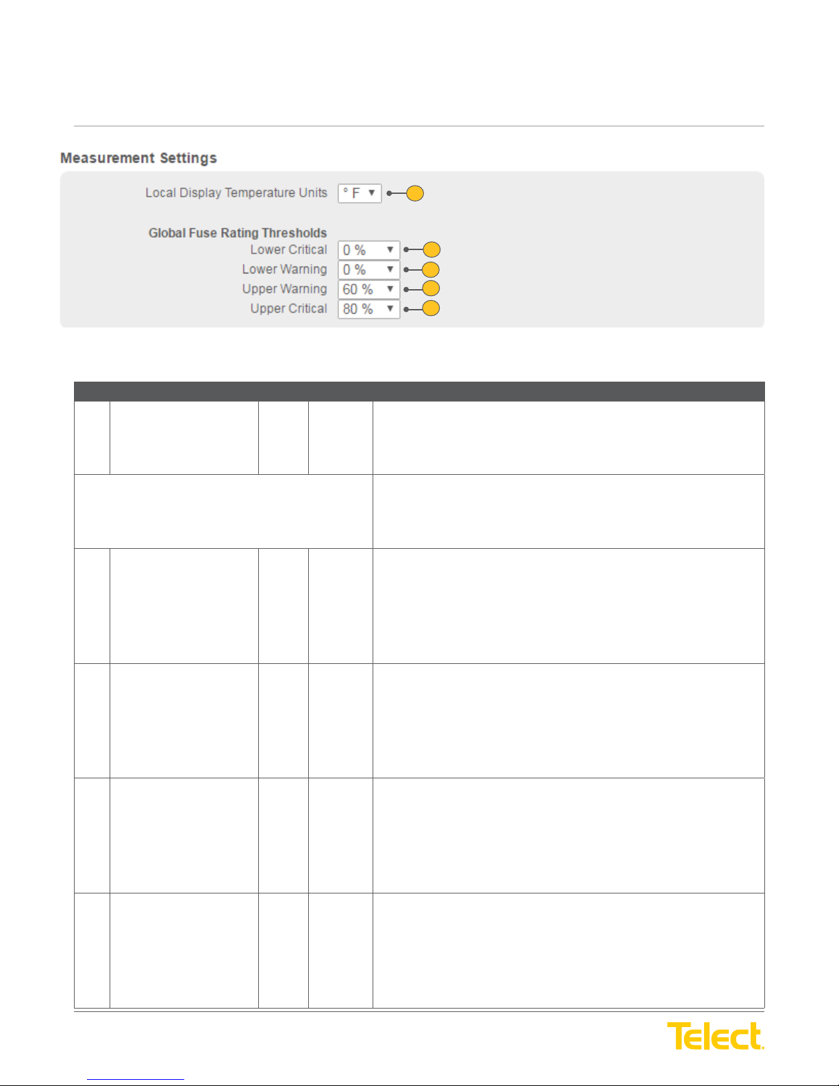
Controller Tab :: Measurement Settings Screen
Ref. Field Type Value Description
1 Temperature Units Select Drop down
Global Fuse Rating Thresholds A percentage of a circuit’s breaker range or fuse range as the threshold value
User Guide
1
2
3
4
5
Figure 13 - Measurement Settings Screen
Sets how temperature readings will display.
menu
From the Temperature Units drop down menu, select from:
o
F: Fahrenheit
o
C: Centigrade
for alarms.
2 Lower Critical Select Drop down
menu
3 Lower Warning Select Drop down
menu
4 Upper Warning Select Drop down
menu
5 Upper Critical Select Drop down
menu
The following fi elds allow threshold values to be set to indicate lower or higher
than normally expected current ranges.
Lower Critical is a user defi ned threshold that is a percentage of the Global
Fuse Rating and indicates a lower than expected measurement, defi ned as a
critical alarm.
Default is: 0%
From the Lower Critical drop down menu, select from: 0% to 100% in
5% increments.
Lower Warning is a user defi ned threshold that is a percentage of the Global
Fuse Rating and indicates a lower than expected measurement, defi ned as a
warning alarm.
Default is: 0%
From the Lower Warning drop down menu, select from: 0% to 100% in
5% increments.
Upper Warning is user defi ned threshold that is a percentage of the Global
Fuse Rating and indicates a higher than expected measurement, defi ned as a
warning alarm.
Default is: 60%
From the Upper Warning drop down menu, select from: 0% to 100% in
5% increments.
Upper Critical is a user defi ned threshold that is a percentage of the Global
Fuse Rating and indicates a higher than expected measurement, defi ned as a
critical alarm.
© Telect, Inc. All rights reserved. 3.22.17 v.3
1.509.926.6000 :: telect.com
Default is: 80%
From the Upper Critical drop down menu, select from: 0% to 100% in
5% increments.
15
Page 16
nrgSMART
nrgSMART
™
Controller Confi guration Guide
POWER ::
User Guide
™
Controller Confi guration Guide
POWER ::
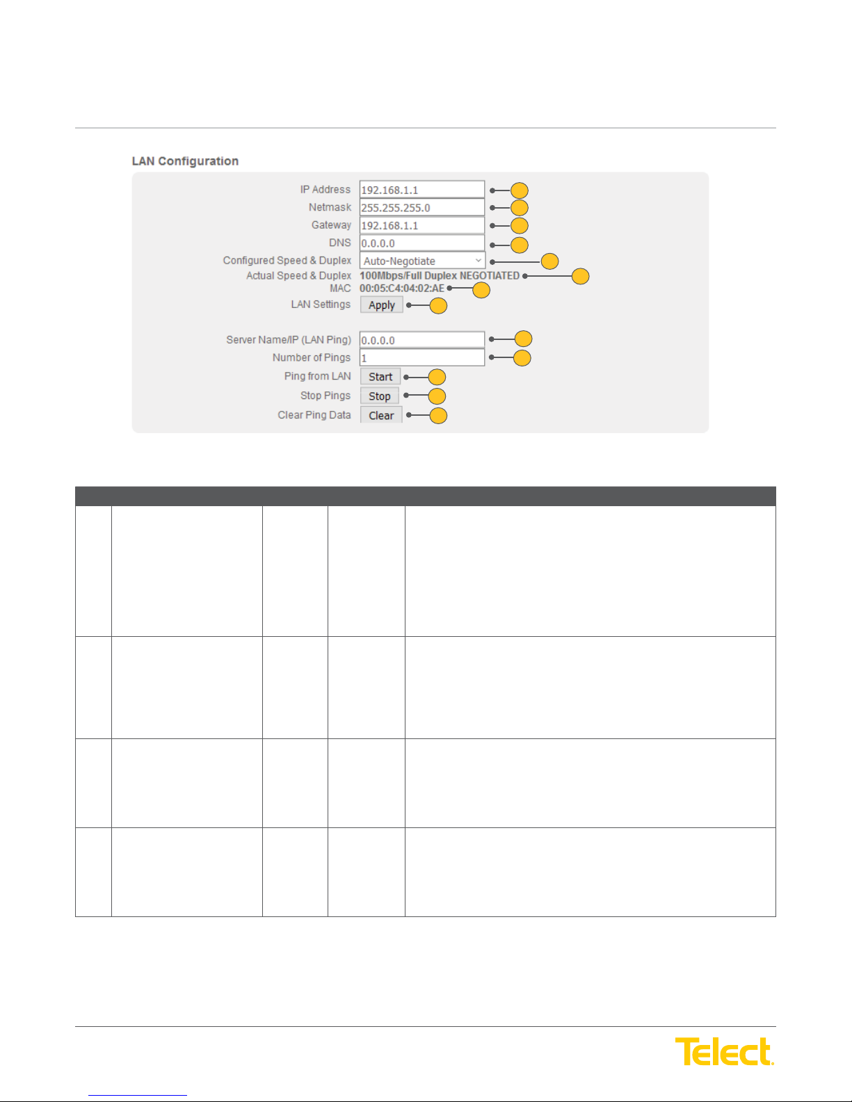
Controller Tab :: LAN Confi guration Screen
Ref. Field Type Value Description
1 IP Address Input Text Local Area Network IP address identifi ed by a series of numbers
User Guide
1
2
3
4
5
6
7
8
9
10
11
12
13
Figure 14 - LAN Confi guration Screen
separated by periods.
Enter the LAN IP address. This fi eld accepts four groups of numbers
separated by periods with up to three numbers in each group (a total of
15 characters, including periods). Each group can be in the range
of: 0 - 255.
NOTE: Default IP address is shown above of 192.168.1.1
2 Netmask Input Text Local Area Network Netmask that defi nes the range of IP addresses
to use.
Enter the LAN Netmask address. This fi eld accepts four groups of
numbers separated by periods with up to three numbers in each group (a
total of 15 characters, including periods). Each group can be in the range
of: 0 - 255.
3 Gateway Input Text Local Area Network Gateway address that is used to bridge networks.
Enter the LAN Gateway address. This fi eld accepts four groups of
numbers separated by periods with up to three numbers in each group (a
total of 15 characters, including periods). Each group can be in the range
of: 0 - 255.
4 DNS Input Text Local Area Network Domain Name Server address.
Enter the LAN DNS address. This fi eld accepts four groups of numbers
separated by periods with up to three numbers in each group (a total of
15 characters, including periods). Each group can be in the range
of: 0 - 255.
© Telect, Inc. All rights reserved. 3.22.17 v.3
1.509.926.6000 :: telect.com
16
Page 17
nrgSMART
nrgSMART
™
Controller Confi guration Guide
POWER ::
User Guide
™
Controller Confi guration Guide
POWER ::
Controller Tab :: LAN Confi guration Screen
Ref. Field Type Value Description
5 Confi gured Speed
and Duplex
6 Actual Speed and Duplex Read Only Text Displays the actual Speed and Duplex the Ethernet port is connected at.
7 MAC Read Only Text Displays the Wide Area Network MAC address as six 2-digit characters
8 LAN Settings “Apply” Select Button After changing LAN settings you must select the “apply” button for
9 Server Name/IP (LAN Ping) Input Text You can ping a remote computer or server to verify connectivity. Insert IP
10 Number of Pings Input Text Insert the number of pings you want to send to the remote device.
11 Ping from LAN Select Button Start the pinging sequence to the remote device.
12 Stop Pings Select Button Stop the pinging sequence to the remote device.
13 Clear Ping Data Select Button Remove the ping responses from remote devices.
User Guide
Select Drop down
menu
Manually set the Speed and Duplex of the LAN Ethernet port. There are
fi ve options:
Auto-negotiate
100 Mbps Full Duplex
100 Mbps Half Duplex
10 Mbps Full Duplex
10 Mbps Half Duplex
NOTE: Telect recommends manually setting your Speed and Duplex to
the negotiated speed on initial connection. Default is Auto-negotiate.
separated by a colon.
changes to take affect.
address of that device here.
Default is 1.
© Telect, Inc. All rights reserved. 3.22.17 v.3
1.509.926.6000 :: telect.com
17
Page 18
nrgSMART
nrgSMART
™
Controller Confi guration Guide
POWER ::
User Guide
™
Controller Confi guration Guide
POWER ::
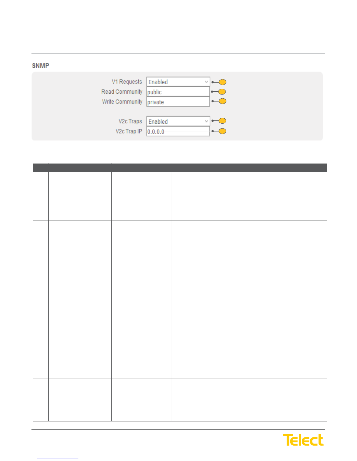
Controller Tab :: SNMP Screen
Ref. Field Type Value Description
1 V1 Requests Select Drop down
2 Read Community Input Text Defi nes the community body to have Version 1 Read rights.
User Guide
Figure 15 - SNMP Screen
Allows use of SNMP Version 1 protocol. SNMP must be enabled for this
Menu
fi eld to allow input.
From the Version 1 drop down menu, select Enabled to allow Version 1
protocol or select Disabled to prevent it.
Note: Version 1 has no security. When Version 1 is enabled, associated
fi elds can be defi ned.
SNMP and Version 1 must be enabled for this fi eld to allow input.
Enter the community string to have SNMP V1 Read rights.
1
2
3
4
5
Generally, this fi eld displays either “public” or “private” although other
groups or individual names can be added. This fi eld accepts up to 19
characters. Valid characters are upper/lowercase letters, numbers,
symbols and spaces.
3 Write Community Input Text Defi nes the community body to have Version 1 Write rights.
SNMP and Version 1 must be enabled for this fi eld to allow input.
Enter the community string to have SNMP V1 Write rights.
Generally, this fi eld displays either “public” or “private” although individual
names can be added as well. If no V1 Write rights are to be assigned,
leave this fi eld blank. This fi eld accepts up to 19 characters. Valid
characters are upper/lowercase letters, numbers, symbols and spaces.
4 V2c Traps Select Drop down
menu
5 V2c Trap IP Input Text The Network Management System’s IP address that will receive the
SNMP Traps allows the network device to send an alert without receiving
a request from the SNMP Manager. Alerts are sent at the time an event
(i.e. fuse alarm, threshold alarm error, etc.) occurs and are not stored in
the MIB.
SNMP must be enabled for this fi eld to allow input.
From the SNMP Traps drop down menu, select Enabled to allow SNMP
Traps or select Disabled to prevent them. When set to Enabled, the
SNMP Traps IP fi elds can be defi ned.
SNMP Traps message. SNMP and SNMP Traps must be enabled for this
fi eld to allow input.
Enter the IP address that will receive the SNMP Traps message. This
fi eld accepts four groups of numbers separated by periods with up to
three numbers in each group (a total of 15 characters, including periods).
© Telect, Inc. All rights reserved. 3.22.17 v.3
1.509.926.6000 :: telect.com
18
Page 19
nrgSMART
nrgSMART
™
Controller Confi guration Guide
POWER ::
User Guide
™
Controller Confi guration Guide
POWER ::
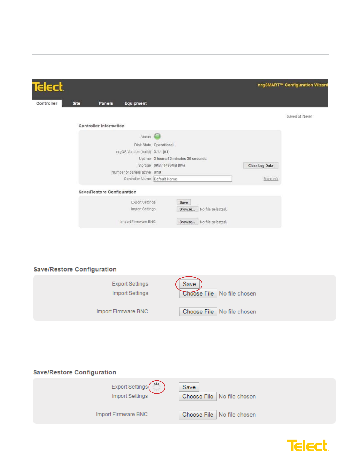
2.3 Firmware Upgrade Procedure
User Guide
Step 1: Export settings to save by clicking “Save” next to Export Settings
Step 2: Wait until browser begins download of settings fi le.
NOTE: This could take a few minutes if the controller has a lot of panels or settings.
© Telect, Inc. All rights reserved. 3.22.17 v.3
1.509.926.6000 :: telect.com
19
Page 20
nrgSMART
nrgSMART
™
Controller Confi guration Guide
POWER ::
User Guide
™
Controller Confi guration Guide
POWER ::
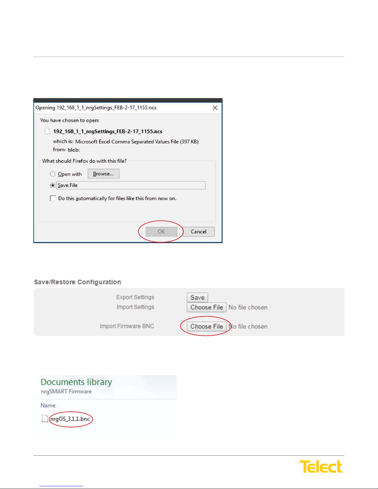
Step 3: Save the settings in a folder where it won’t be lost. It saves to the downloads folder by default. Verify fi le has been saved into specifi ed
folder when complete.
User Guide
Step 4: After settings are saved, click Choose File next to Import Firmware BNC.
Step 5: Navigate to where the BNC fi le is located and select it.
© Telect, Inc. All rights reserved. 3.22.17 v.3
1.509.926.6000 :: telect.com
20
Page 21
nrgSMART
nrgSMART
™
Controller Confi guration Guide
POWER ::
User Guide
™
Controller Confi guration Guide
POWER ::
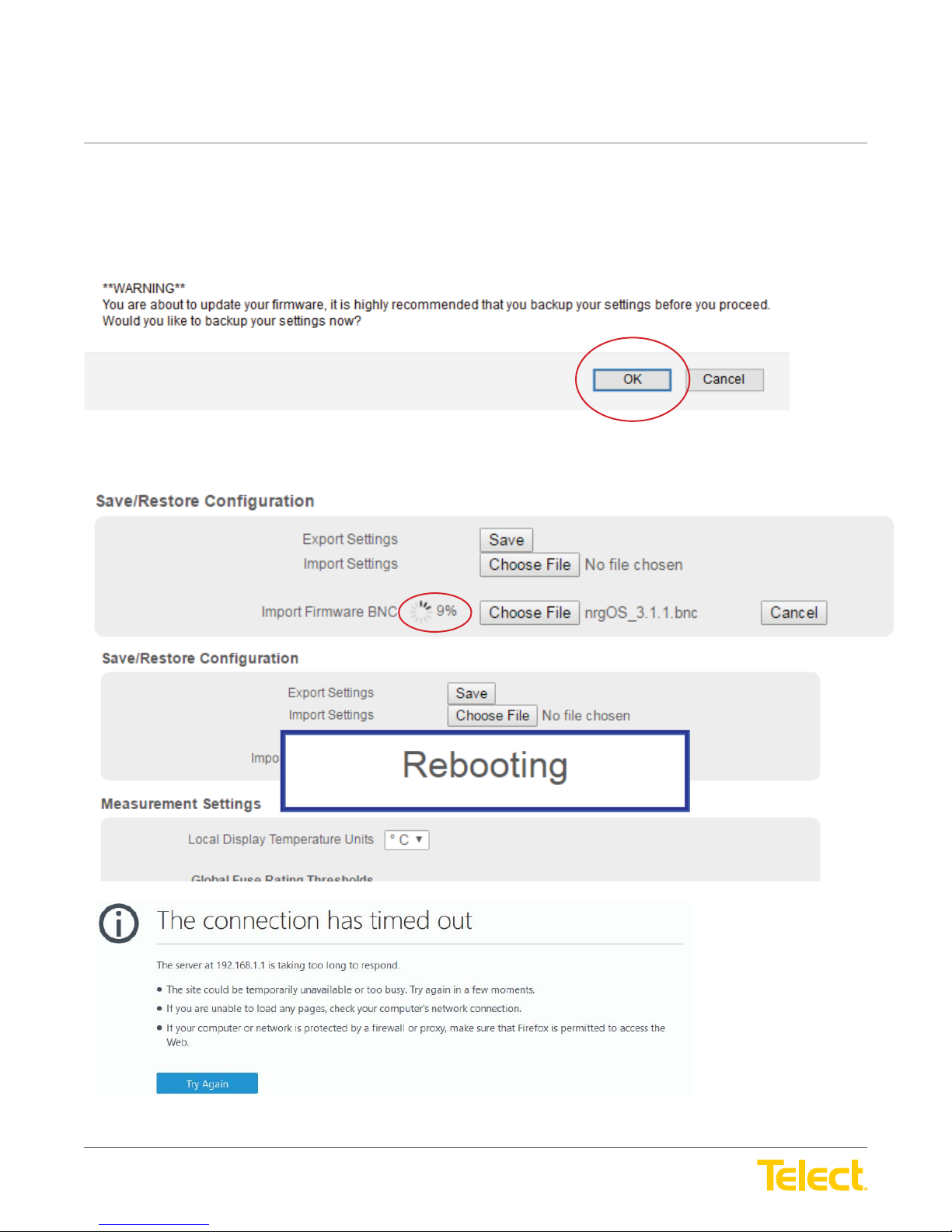
Step 6: When warning pops up, select ‘OK’ to resave settings. This is to make sure settings are saved.
Note: When updating fi rmware you will be prompted to save your confi guration by selecting “OK”. This is optional as we just saved the
confi guration in the previous step. You can select “Cancel” to prevent saving the confi guration again.
Step 7: Firmware update will begin automatically after settings have been saved. Do not navigate away from this
page while uploading.
User Guide
Once your browser times out wait 1-2 minutes for the controller to restart and then refresh your browser.
© Telect, Inc. All rights reserved. 3.22.17 v.3
1.509.926.6000 :: telect.com
21
Page 22
nrgSMART
nrgSMART
™
Controller Confi guration Guide
POWER ::
User Guide
™
Controller Confi guration Guide
POWER ::
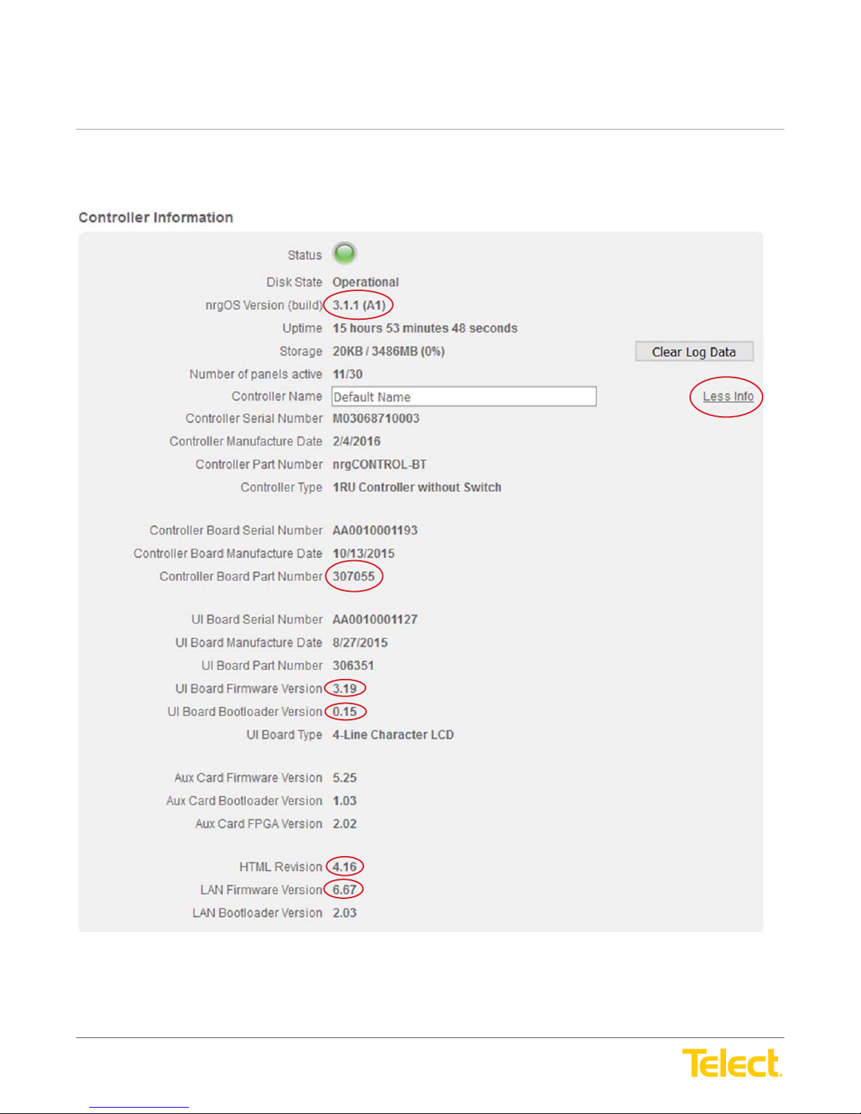
Step 8: Once fi rmware has uploaded, please verify that the proper version was uploaded correctly by clicking on “More Info” on the fi rst page
and reviewing the items circled against the release note.
User Guide
Circled versions for 3.1.1 are shown. See release notes for other versions.
If any of the versions do not match:
1. First re-install fi rmware
2. If they still do not match after re-install contact Telect Technical Support at 1-509-926-6000
© Telect, Inc. All rights reserved. 3.22.17 v.3
1.509.926.6000 :: telect.com
22
Page 23
nrgSMART
nrgSMART
™
Controller Confi guration Guide
POWER ::
User Guide
™
Controller Confi guration Guide
POWER ::
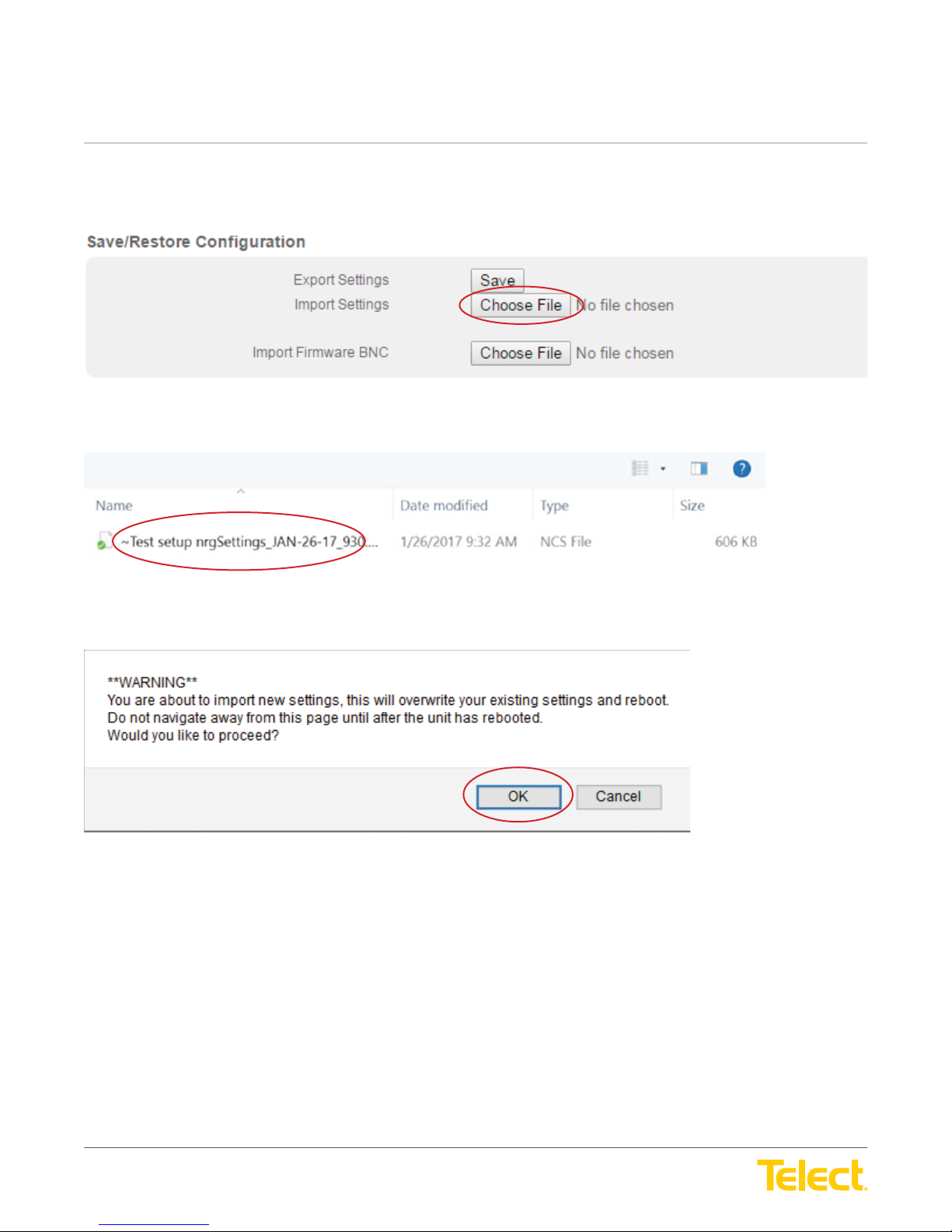
Step 9: After fi rmware upload has been verifi ed, upload your recently saved confi guration fi le as some settings have been overwritten during
the fi rmware upgrade process.
Navigate to recently saved .NCS fi le.
User Guide
Select OK to initiate upload.
© Telect, Inc. All rights reserved. 3.22.17 v.3
1.509.926.6000 :: telect.com
23
Page 24
nrgSMART
nrgSMART
™
Controller Confi guration Guide
POWER ::
User Guide
™
Controller Confi guration Guide
POWER ::
User Guide
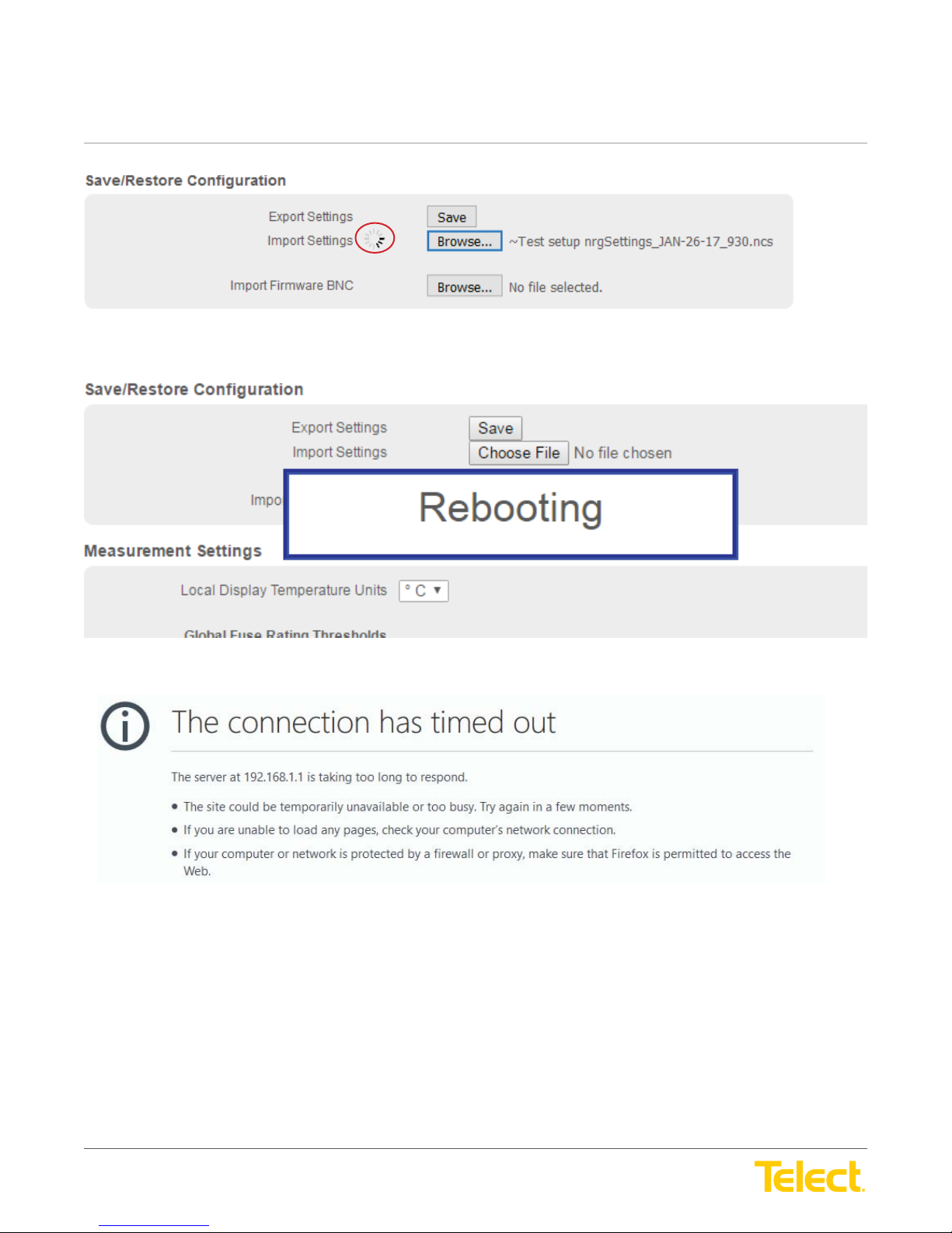
Once your browser times out wait 1-2 minutes for the controller to restart and then refresh your browser.
Step 10: Verify your settings.
© Telect, Inc. All rights reserved. 3.22.17 v.3
1.509.926.6000 :: telect.com
24
Page 25
nrgSMART
nrgSMART
™
Controller Confi guration Guide
POWER ::
User Guide
™
Controller Confi guration Guide
POWER ::
User Guide
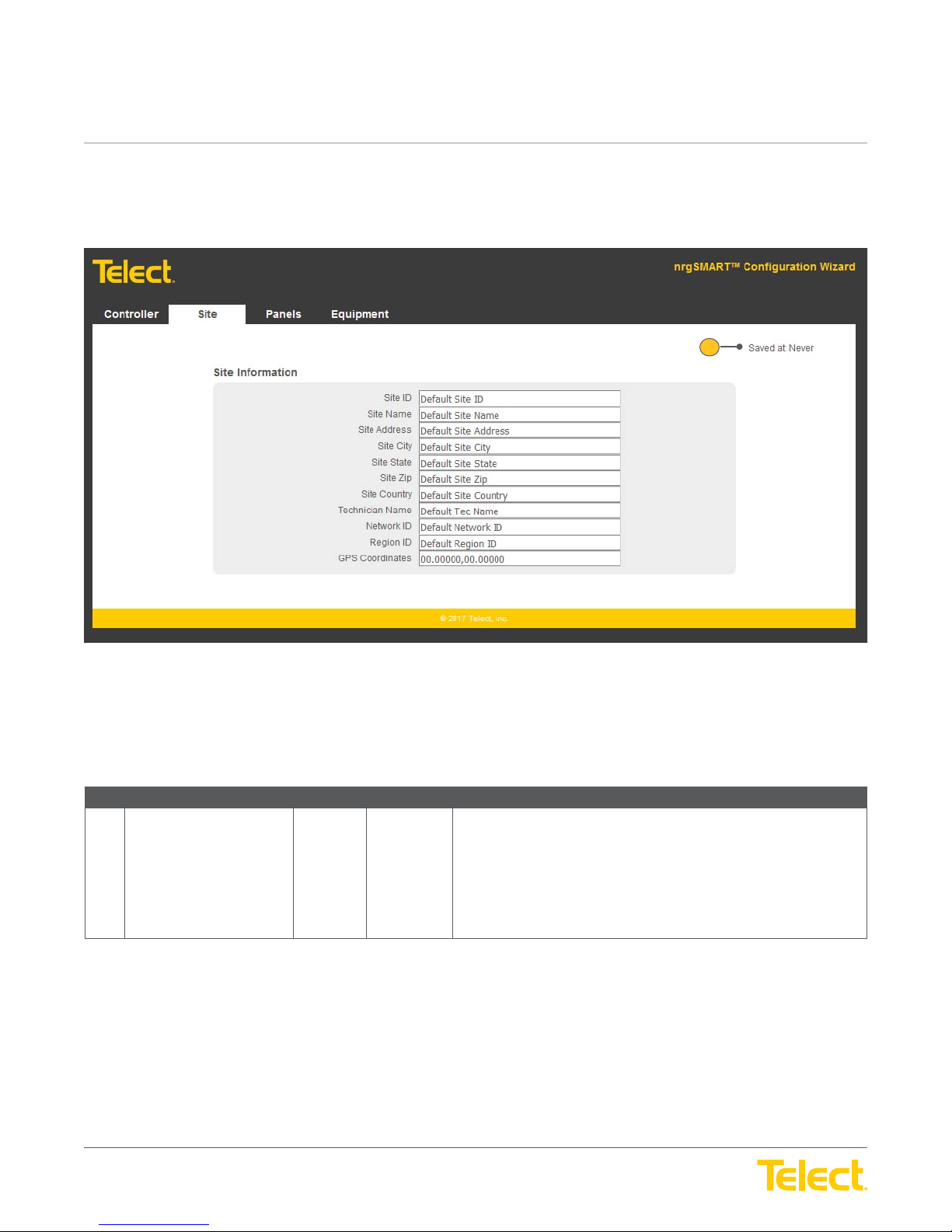
3. Site Tab Settings
The
Site Tab
is comprised of the main window (
Site Tab Window
) and the
Site Information Screen
where site location information is defi ned.
1
Figure 16 - Site Tab Window
Site Tab Window
Ref. Field Type Value Description
1 Saved At Read Only Text The date and time that information in the
NOTE: When a fi eld is updated within the Site Tab, clicking outside of the
fi eld saves the information and updates the Saved At time.
Field settings are:
Never: Data not saved
Date/Time: mm/dd/yyyy HH:MM:SS (AM/PM)
Site Tab
was last saved.
© Telect, Inc. All rights reserved. 3.22.17 v.3
1.509.926.6000 :: telect.com
25
Page 26
nrgSMART
nrgSMART
™
Controller Confi guration Guide
POWER ::
User Guide
™
Controller Confi guration Guide
POWER ::
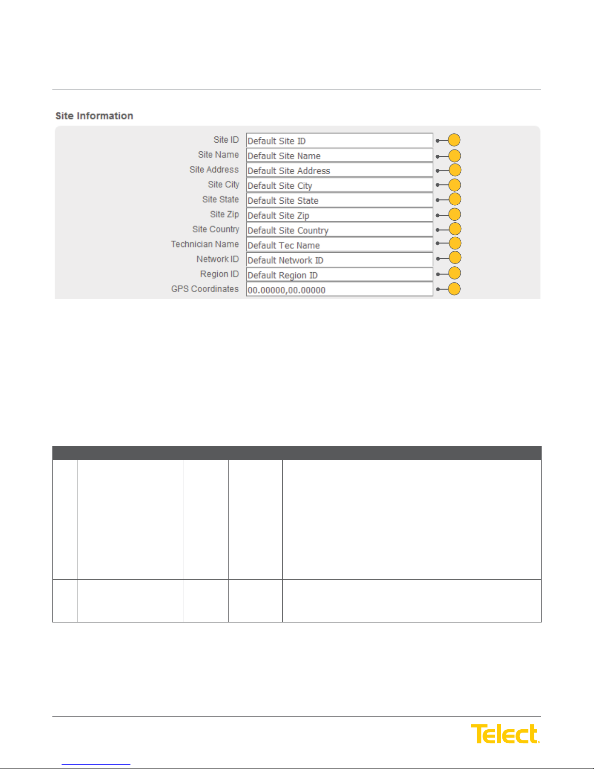
The fi elds in the
Site Information Screen
User Guide
1
2
3
4
5
6
7
8
9
10
11
Figure 17 - Site Information Screen
can be defi ned in one of the following two ways:
1. SNMP Only: When SNMP is enabled, the fi elds can be defi ned through your SNMP manager or defi ned locally.
(See
SNMP Screen
2. None: When not connected to SNMP these fi elds can be defi ned locally.
Site Tab :: Site Information Screen
Ref. Field Type Value Description
1 Site ID Read Only
2 Site Name Read Only
in the
Controller Tab
or
Input
or
Input
section for more information about SNMP.)
Text A descriptor that uniquely defi nes this site, setting it apart from other sites
in the network.
To defi ne the fi eld locally, enter the unique site descriptor as the Site
ID. This fi eld accepts up to 40 characters. Valid characters are upper/
lowercase letters, numbers and the underscore symbol. (Do not use any
other symbols.)
NOTE: Choose the Site ID carefully. Once the Site ID is defi ned it cannot
be changed/modifi ed. To remove it, you have to perform a Reset Settings
from the Controller Tab and all site confi guration information must
be re-entered.
Text The Site Name distinguishes one site from another site.
Enter a Site Name. This fi eld accepts up to 40 characters. Valid
characters are upper/lowercase letters, numbers, symbols and spaces.
© Telect, Inc. All rights reserved. 3.22.17 v.3
1.509.926.6000 :: telect.com
26
Page 27
nrgSMART
nrgSMART
™
Controller Confi guration Guide
POWER ::
User Guide
™
Controller Confi guration Guide
POWER ::
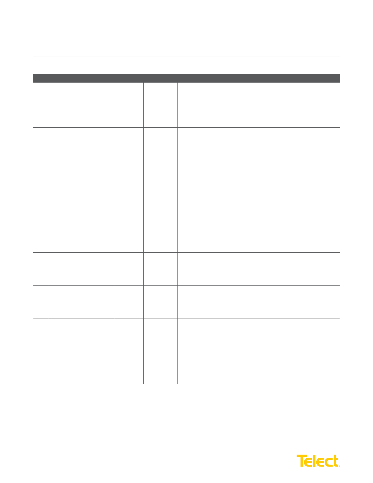
Site Tab :: Site Information Screen
Ref. Field Type Value Description
3 Site Address Read Only
4 Site City Read Only
5 Site State Read Only
6 Site Zip Read Only
7 Site Country Read Only
8 Technician Name Read Only
9 Network ID Read Only
10 Region ID Read Only
11 GPS Coordinates Read Only
User Guide
or
Input
or
Input
or
Input
or
Input
or
Input
or
Input
or
Input
or
Input
or Input
Text The Street Address for the site.
Enter the Site Address. This fi eld accepts up to 40 characters. Valid
characters are upper/lowercase letters, numbers, symbols and spaces.
NOTE: The exact physical location of the site is shown in the GPS
Coordinates fi eld.
Text City where the site is located.
Enter the City where the site is located. This fi eld accepts up to 40
characters. Valid characters are upper/lowercase letters, numbers,
symbols and spaces.
Text State where the site is located.
Enter the State where the site is located. This fi eld accepts up to 40
characters. Valid characters are upper/lowercase letters, numbers,
symbols and spaces.
Text Zip Code for this site.
Enter the Zip Code for the site. This fi eld accepts up to 40 characters.
Use numbers and a dash.
Text Country where the site is located.
Enter the Country where the site is located. This fi eld accepts up to
40 characters. Valid characters are upper/lowercase letters, numbers,
symbols and spaces.
Text Lead technician or technician responsible for the site.
Enter the Technician’s Name at the site. This fi eld accepts up to 40
characters. Valid characters are upper/lowercase letters, numbers,
symbols and spaces.
Text Identifi es the Network that the site is connected to.
Enter the Network ID for the site. This fi eld accepts up to 40 characters.
Valid characters are upper/lowercase letters, numbers, symbols
and spaces.
Text Identifi es the Region ID where the site is located.
Enter the Region ID for this site. This fi eld accepts up to 40 characters.
Valid characters are upper/lowercase letters, numbers, symbols
and spaces.
Text The GPS coordinates showing the latitude/longitude location of the site.
This fi eld indicates coordinates in decimal degrees.
© Telect, Inc. All rights reserved. 3.22.17 v.3
1.509.926.6000 :: telect.com
Enter the GPS coordinates where this site is located. This fi eld accepts
up to 40 characters. Use numbers, comma, minus and period symbols.
27
Page 28
nrgSMART
nrgSMART
™
Controller Confi guration Guide
POWER ::
User Guide
™
Controller Confi guration Guide
POWER ::
User Guide
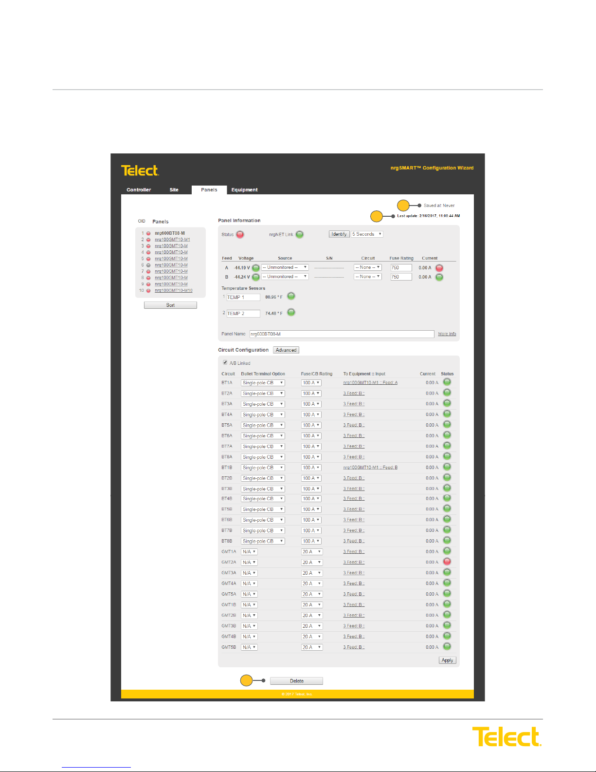
4. Panels Tab Settings
The
Panels Tab
Tab Window
is comprised of the main window (
displays date and time settings; within the window are screens that allow other panel related settings to be defi ned or viewed.
Panels Tab Window
) and screens that contain settings for the panels installed. The
1
2
Panels
© Telect, Inc. All rights reserved. 3.22.17 v.3
1.509.926.6000 :: telect.com
3
Figure 18 - Panels Tab Window
28
Page 29
nrgSMART
nrgSMART
™
Controller Confi guration Guide
POWER ::
User Guide
™
Controller Confi guration Guide
POWER ::
Panels Tab Window
Ref. Field Type Value Description
1 Saved At Read Only Text The date and time that information in the
2 Last Update Read Only Text Displays the current date and time.
3 Delete Select Button Removes the selected panel and all of the associated information from
User Guide
Panels Tab
NOTE: When a fi eld is updated within a window or screen in the Panels
Tab, clicking outside of the fi eld saves the information and updates the
Saved At time.
Field settings are:
Never: Data not saved
Date/Time: mm/dd/yyyy HH:MM:SS (AM/PM)
Displays as: mm/dd/yyyy HH:MM:SS (AM/PM)
the
Panels Tab
Select the Delete button to remove the selected panel and associated
information from the
NOTE: When a panel is deleted, the rows below the panel name row (in
the Panels Screen) will shift up.
.
Panels Tab
.
was last saved.
© Telect, Inc. All rights reserved. 3.22.17 v.3
1.509.926.6000 :: telect.com
29
Page 30
nrgSMART
nrgSMART
™
Controller Confi guration Guide
POWER ::
User Guide
™
Controller Confi guration Guide
POWER ::
1
User Guide
BDFB Only
2
3
3
1
2
4
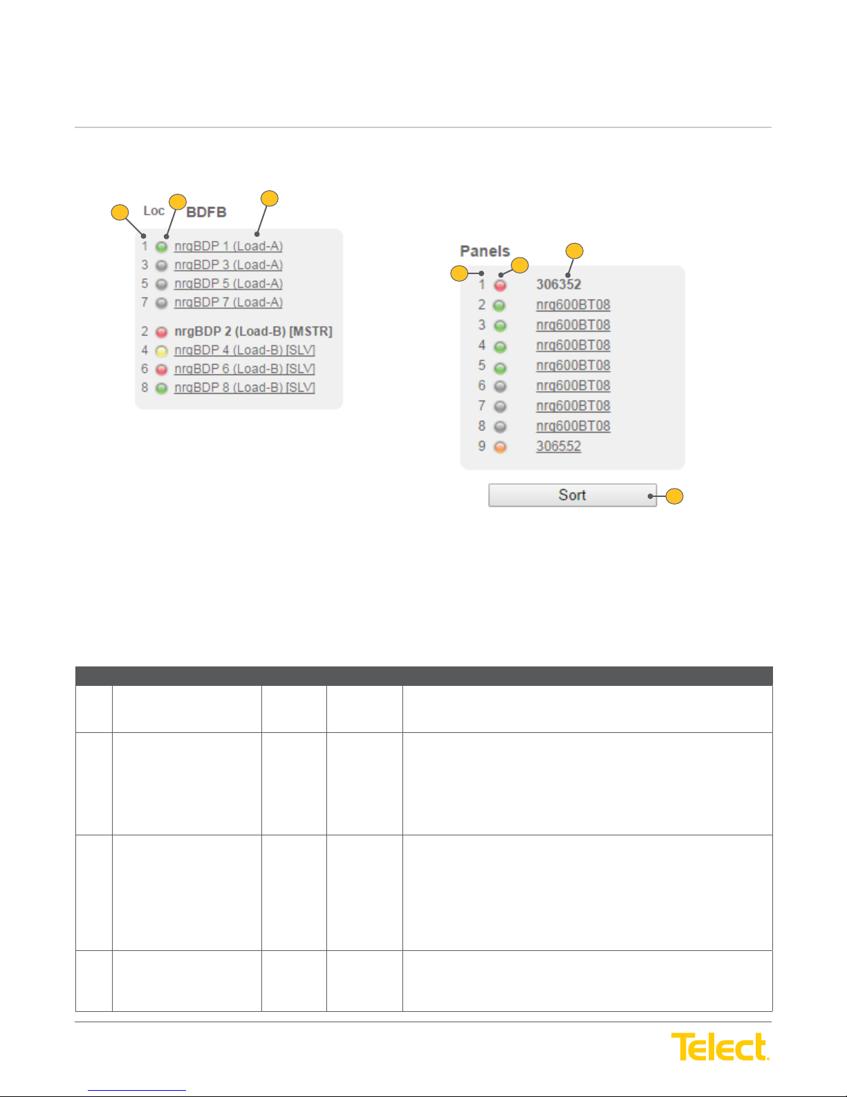
Figure 19 - BDFB and Panels Screens
When BDFB panels are installed, a
Screen
displaying the row, status and name to identify the BDFB panels.
NOTE: The fi elds in these tables are column headings that defi ne data displayed in rows within the columns.
(This does not apply to the Sort button.)
Panels Tab :: Panels Screen
Ref. Field Type Value Description
1 Location (column)
BDFB Only
Number for Controller
2 Light (column) Read Only Light The overall state of the panel.
3 Panel Name (column) Select Text The Panel Name distinguishes one panel from another.
4 Sort Select Button Allows
BDFB Screen
Read Only Text BDFB Only: Position number in BDFB are all odd numbered panels on
appears as the
Panels Screen
Left (Load A) and all even numbered panels are on the right (Load B).
Controller Only: Number of Devices
Green: Normal operation.
Yellow: Warning threshold reached.
Orange: Critical threshold reached.
Red: A blown fuse or a tripped breaker.
Gray: Not connected.
Select a Panel Name to view or modify. When selected, the panel name
becomes bold and associated fi elds populate the screens in the
Panels Information and Curcuit confi guration fi elds
BDFB Only: All odd numbered panels on Left (Load A) and all even
numbered panels are on the right (Load B) for panels in a nrgBDFB.
. The fi elds in the
Panels Screen
BDFB Screen
row order to be modifi ed.
are similar to the
.
Panels
© Telect, Inc. All rights reserved. 3.22.17 v.3
1.509.926.6000 :: telect.com
Select the Sort button to open the
row order.
30
Sort Order Screen
and modify
Page 31
nrgSMART
nrgSMART
™
Controller Confi guration Guide
POWER ::
User Guide
™
Controller Confi guration Guide
POWER ::
User Guide
1
4 5
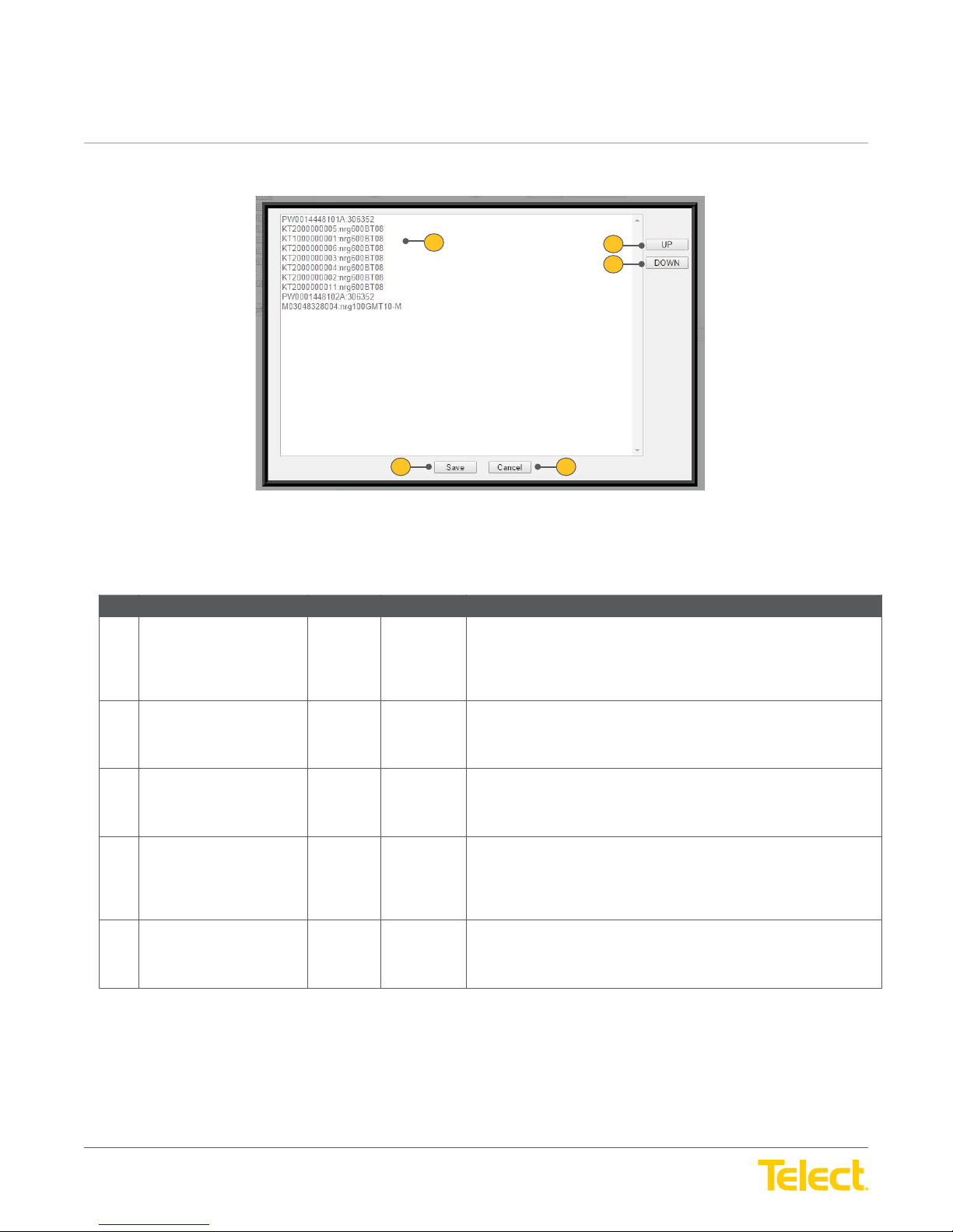
Figure 20 - Sort Order Screen
2
3
Panels Tab :: Panels Screen > Sort Order Screen
Ref. Field Type Value Description
1 Name and Row Select Text The name of a panel on a selected row. Allows the order of
Screen
panels to display in a different order.
Select to highlight a panel row (identifi ed by part number and
panel name).
2 Up Select Button Moves the selected row to display at a higher row number in the
Panels Screen
Select the Up button to move the highlighted row up.
3 Down Select Button Moves the selected row to display at a lower row number in the
Panels Screen
Select the Down button to move the highlighted row lower.
4 Save Select Button Changes the order of rows in the
shown in the
Select the Save button to save row settings and return to the
Panels Screen
5 Cancel Select Button Leaves the
Select the Cancel button to return to the
any changes.
.
.
Sort Order Screen
.
Sort Order Screen
Panels Screen
.
without keeping modifi ed settings.
to display in the order
Panels Screen
Panels
without making
© Telect, Inc. All rights reserved. 3.22.17 v.3
1.509.926.6000 :: telect.com
31
Page 32
nrgSMART
nrgSMART
™
Controller Confi guration Guide
POWER ::
User Guide
™
Controller Confi guration Guide
POWER ::
5
14
User Guide
1
7
6
16
15
2
8
17
9
18
3
10
4
11
12
13
19
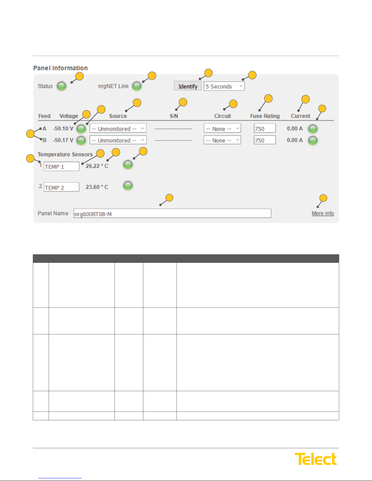
Figure 21 - Panel Information Screen
Panels Tab :: Panel Information Screen
Ref. Field Type Value Description
1 Status Read Only Light Summarizes the current threshold status for this panel.
Green: Normal operation.
Yellow: Warning threshold reached.
Orange: Critical threshold reached.
Red: A blown fuse or tripped breaker.
Gray: Not connected.
2 nrgNET Link Read Only Light Shows if the panel is connected to the controller and communicating.
Green: Communicating and connected.
Gray: Not connected.
3
Identify
and
and
4
Find (down arrow)
5 Feed Read Only Text Identifi es the Feed (A or B)
Select Button
and
Drop down
menu
Assists in locating the selected panel by blinking a light on the physical
panel for a specifi c amount of time.
Select the Identify button to blink the nrg LED, a light that is centrally
located on the front of the panel.
To specify how long the light will blink, select the Arrow button to open
the Find drop down menu and select from:
5 seconds, 30 seconds, 60 seconds, 5 minutes, and 10 minutes
6 Voltage Read Only Text A numerical display showing the voltage reading for this Feed.
© Telect, Inc. All rights reserved. 3.22.17 v.3
1.509.926.6000 :: telect.com
Associated fi elds (total current, voltage and fuse alarm)
32
Page 33
nrgSMART
nrgSMART
™
Controller Confi guration Guide
POWER ::
User Guide
™
Controller Confi guration Guide
POWER ::
Panels Tab :: Panel Information Screen
Ref. Field Type Value Description
7 Light Read Only Light Indicates the threshold status of the total voltage coming into the Feed.
8 Source Read Only Text Displays equipment input label delivering power from the Equipment
9 S/N Read Only Text A 12-digit number of the Source device consisting of uppercase letters
10 Circuit Select Drop down
11 Fuse Rating Read Only Light The state of all fuses in this Feed.
12 Current Read Only Text A numerical display showing the total current, in amps, coming into
13 Light Read Only Light Indicates the threshold status of the total current coming into a Feed.
User Guide
Green: Normal operation.
Yellow: Warning threshold reached.
Orange: Critical threshold reached.
Red: A blown fuse or tripped breaker.
Gray: Not connected.
in the equipment list. The equipment input label is defi ned in the
Equipment Tab.
and numbers.
Circuit position of Source device.
Menu
this Feed.
Green: Normal operation.
Yellow: Warning threshold reached.
Orange: Critical threshold reached.
Red: A blown fuse or tripped breaker.
Gray: Not connected.
Temperature Sensors Temperature sensors collect temperature data from equipment and
display those readings.
Each panel can have up to two Temperature Sensors. BDFB panels
have one.
Associated values can be defi ned in the following fi elds.
14 Temperature Sensor
Number
Read Only Text Row number for the temperature sensor.
© Telect, Inc. All rights reserved. 3.22.17 v.3
1.509.926.6000 :: telect.com
33
Page 34
nrgSMART
nrgSMART
™
Controller Confi guration Guide
POWER ::
User Guide
™
Controller Confi guration Guide
POWER ::
Panels Tab :: Panel Information Screen
Ref. Field Type Value Description
15 Temperature Sensor Name Input Text The Temperature Sensor Name distinguishes one temperature sensor
16 Temperature Read Only Text Temperature reading for the temperature sensor.
17 Light Read Only Light The alarm light indicates the threshold status of the temperature sensor.
18 Panel Name Input Text The Panel Name distinguishes one panel from another.
19 More info / Less info Select Toggle View more or fewer screen fi elds.
User Guide
from another.
Enter a Temperature Sensor Name. This fi eld accepts up to 9 characters.
Valid characters are upper/lowercase letters, numbers, symbols
and spaces.
The normal temperature operating range is -40
Green: Normal operation.
Yellow: Warning threshold reached.
Orange: Critical threshold reached.
Red: Outside of temperature operating range.
Gray: Not connected.
Select the Panel Name to view or modify from the
To rename a panel, highlight the name and enter a new name. Valid
characters are upper/lowercase letters, numbers, symbols and spaces.
o
C (-40oF) to 70oC (158oF)
Panels Screen
.
Toggle More info to expand the screen to display additional fi elds or
Less info to hide a portion of the screen.
© Telect, Inc. All rights reserved. 3.22.17 v.3
1.509.926.6000 :: telect.com
34
Page 35
nrgSMART
nrgSMART
™
Controller Confi guration Guide
POWER ::
User Guide
™
Controller Confi guration Guide
POWER ::
User Guide
11
12
BDFB Only
4
2
1
6
5
13
14
7
15
3
10
8
16
9
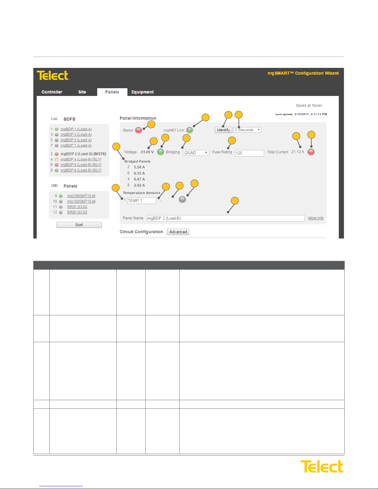
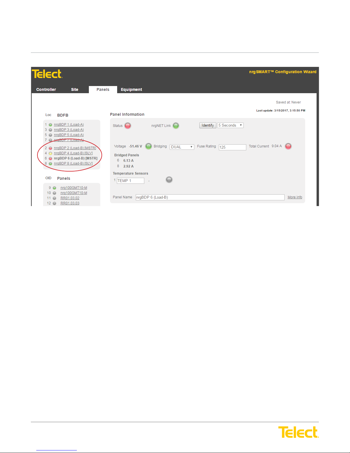
Figure 22 - Quad System: This fi gure depicts a single master system with three slaves
Panels Tab :: Panel Information Screen
Ref. Field Type Value Description
1 Status Read Only Light Summarizes the current threshold status for this panel.
Green: Normal operation.
Yellow: Warning threshold reached.
Orange: Critical threshold reached.
Red: A blown fuse or tripped breaker.
Gray: Not connected.
2 nrgNET Link Read Only Light Shows if the panel is connected to the controller and communicating.
Green: Communicating and connected.
Gray: Not connected.
3
Identify and Find
and
(down arrow)
4
5 Voltage Read Only Text A numerical display showing the voltage reading for this Feed.
6 Light Read Only Light Indicates the threshold status of the voltage coming into the Feed.
Select Button and
Drop down
Menu
Assists in locating the selected panel by blinking a light on the physical
panel for a specifi c amount of time.
Select the Identify button to blink a light that is centrally located on the
front of the panel.
To specify how long the light will blink, select the Arrow button to open
the Find drop down menu and select from:
5 seconds, 30 seconds, 60 seconds, 5 minutes and 10 minutes
© Telect, Inc. All rights reserved. 3.22.17 v.3
1.509.926.6000 :: telect.com
Green: Normal operation.
Yellow: Warning threshold reached.
Orange: Critical threshold reached.
Red: A blown fuse or tripped breaker.
Gray: Not connected.
35
Page 36
nrgSMART
nrgSMART
™
Controller Confi guration Guide
POWER ::
User Guide
™
Controller Confi guration Guide
POWER ::
Panels Tab :: Panel Information Screen
Ref. Field Type Value Description
7 Bridging Mode Read Only Drop down
8 Fuse Rating Input Value Insert the size of breaker in amps.
9 Total Current Read Only Text Total current is the sum of the current. This can be the sum of single,
10 Light Read Only Light Indicates the threshold status of the total current coming into the Feed.
11 Bridging Panels Read Only Shows the current of each slave panel when bridged.
Temperature Sensors Temperature sensors collect temperature data from equipment and
User Guide
menu
Bridging allows you the ability to request data from one device for the
load side A or B. You have the following options:
None: Single device
Dual: One master and one slave
Triple: One master and two slaves
Quad: One master and three slaves
dual, triple or quad.
Green: Normal operation.
Yellow: Warning threshold reached.
Orange: Critical threshold reached.
Red: A blown fuse or tripped breaker.
Gray: Not connected.
display those readings.
Each panel can have up to two Temperature Sensors. BDFB panels
have one.
Associated values can be defi ned in the following fi elds.
12 Temperature Sensor
Number
13 Temperature Sensor
Name
14 Temperature Read Only Text Temperature reading for the temperature sensor.
15 Light Read Only Light The alarm light indicates the threshold status of the temperature sensor.
16 Panel Name Input Text The Panel Name distinguishes one panel from another.
Read Only Text Row number for the temperature sensor.
Input Text The Temperature Sensor Name distinguishes one temperature sensor
from another.
Enter a Temperature Sensor Name. This fi eld accepts up to 9 characters.
Valid characters are upper/lowercase letters, numbers, symbols
and spaces.
The normal temperature operating range is -40°C (-40°F) to 70°C
(158°F).
Green: Normal operation.
Yellow: Warning threshold reached.
Orange: Critical threshold reached.
Red: Outside of temperature operating range.
Gray: Not connected.
Select the Panel Name to view or modify from the
To rename a panel, highlight the name and enter a new name. Valid
characters are upper/lowercase letters, numbers, symbols and spaces.
Panels Screen
.
© Telect, Inc. All rights reserved. 3.22.17 v.3
1.509.926.6000 :: telect.com
36
Page 37
nrgSMART
nrgSMART
™
Controller Confi guration Guide
POWER ::
User Guide
™
Controller Confi guration Guide
POWER ::
User Guide
BDFB Only
Figure 23 - Dual System: This fi gure depicts a dual master system showing the
difference from the previous fi gure of one master system and three slaves
© Telect, Inc. All rights reserved. 3.22.17 v.3
1.509.926.6000 :: telect.com
37
Page 38
nrgSMART
nrgSMART
™
Controller Confi guration Guide
POWER ::
User Guide
™
Controller Confi guration Guide
POWER ::
Panels Tab :: Panel Information Screen
Ref. Field Type Value Description
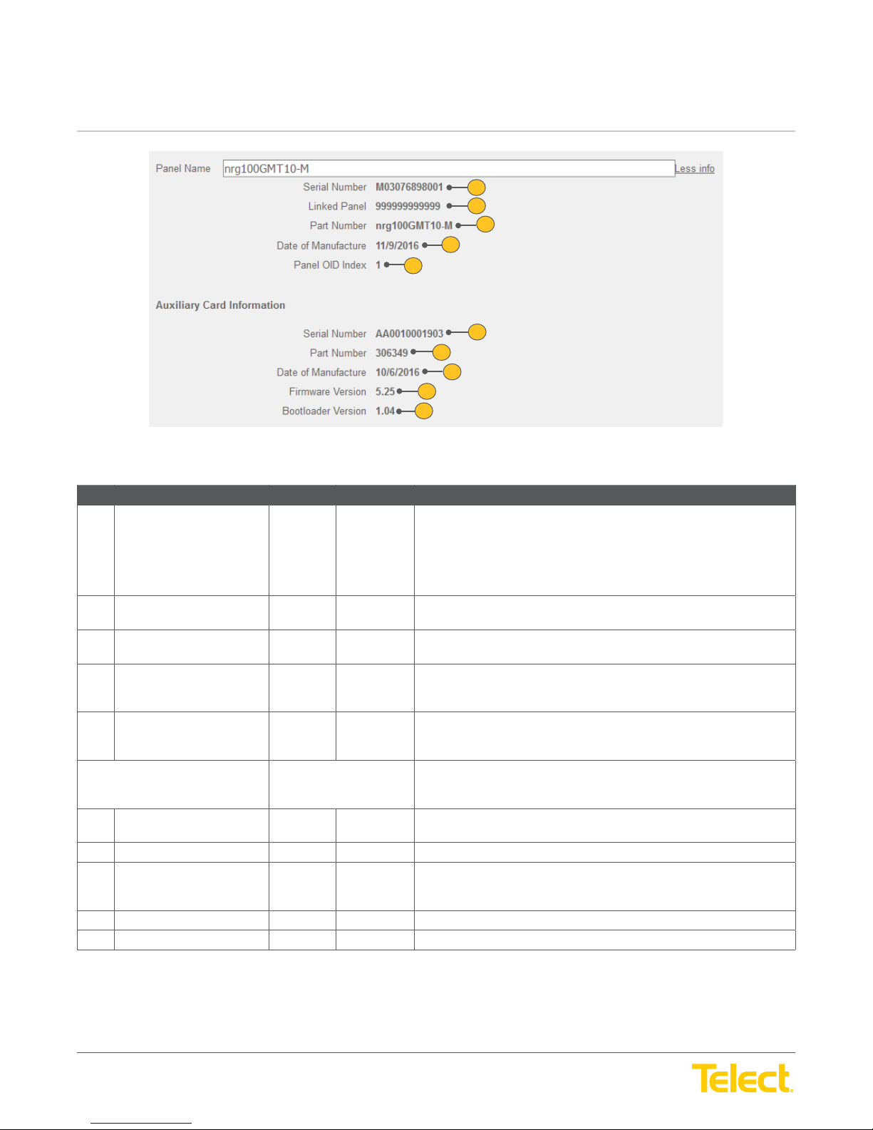
20 Serial Number Read Only Text A 12-digit serial number mounted on the panel consisting of uppercase
User Guide
20
21
22
23
24
25
26
27
28
29
Figure 24 - Panel Information More info/Less info Screen
letters and numbers.
The serial number must be a unique number for each piece of hardware.
Telect recommends using the serial number of the hardware but can use
a convention specifi c to your company or inventory needs.
21 Linked Panel Read Only Text If a Telect panel is used for the source feed the serial number of that
panel will be populated, if not it will display 999999999999.
22 Part Number Read Only Text A string of characters that identify the panel as a part consisting of upper/
lowercase letters, numbers, symbols and spaces.
23 Date of Manufacture Read Only Text The date the panel was manufactured.
Displays as: mm/dd/yyyy
24 Panel OID Index Read Only Text The OID (Object Identifi er) is what the SNMP manager will use to request
data along with the appropriate MIB. Each panel has a unique OID to
collect data from.
Auxiliary Card Information The alarm card in the fuse panel.
The following fi elds display Auxiliary Card information.
25 Serial Number Read Only Text A 12-digit serial number mounted on the Auxiliary Card consisting of
uppercase letters and numbers.
26 Part Number Read Only Text A six digit string of characters that identify the Auxiliary Card.
27 Date of Manufacture Read Only Text Date that the Auxiliary Card was manufactured.
Displays as: mm/dd/yyyy
28 Firmware Version Read Only Text The fi rmware version of the Auxiliary Card.
29 Bootloader Version Read Only Text The bootloader version of the Auxiliary Card.
© Telect, Inc. All rights reserved. 3.22.17 v.3
1.509.926.6000 :: telect.com
38
Page 39
nrgSMART
nrgSMART
™
Controller Confi guration Guide
POWER ::
User Guide
™
Controller Confi guration Guide
POWER ::
3
Panels Tab :: Circuit Confi guration Screen
Ref. Field Type Value Description
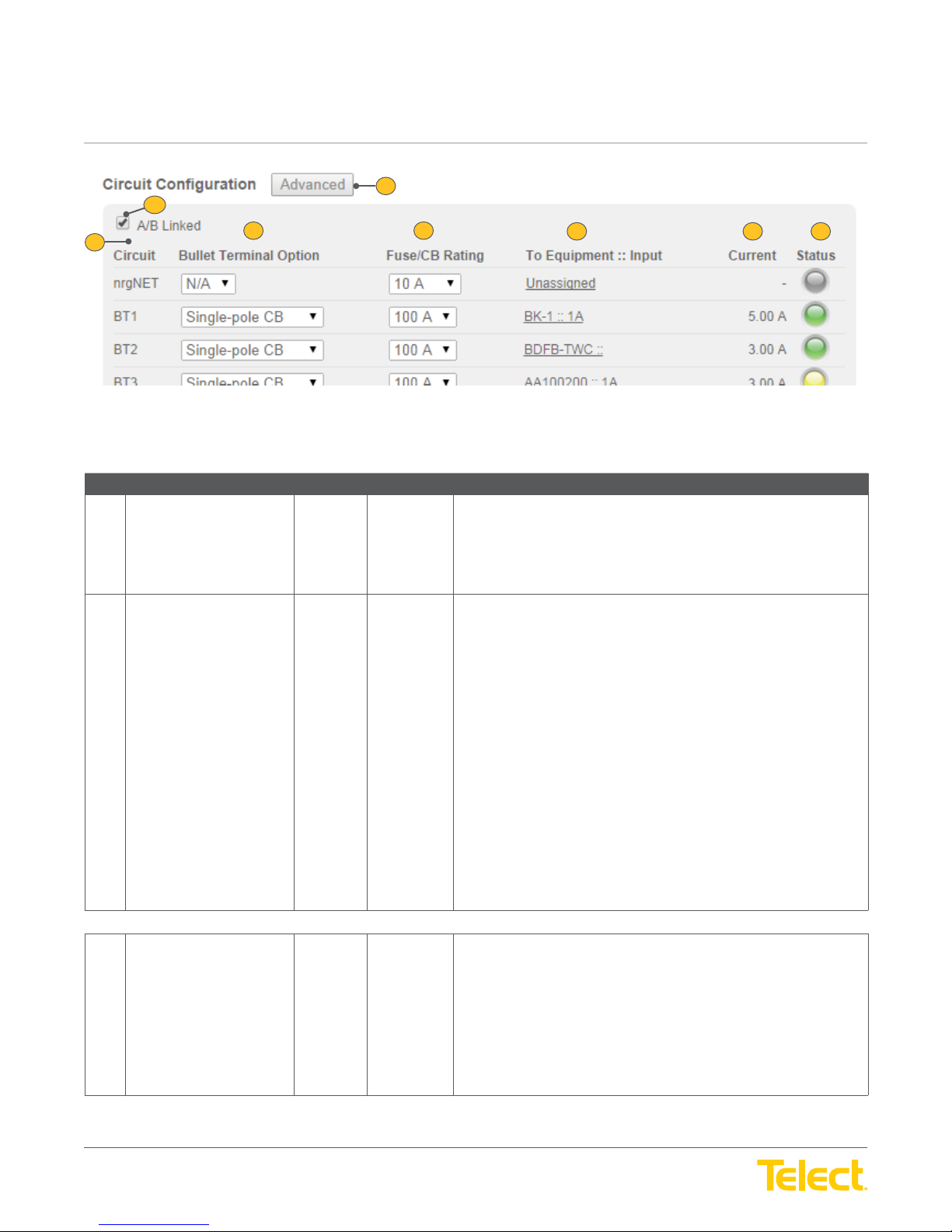
1 Advanced Select Button Allows individual circuit setting alarms to be viewed or modifi ed.
2 A/B Linked Select Checkbox Links and unlinks Feed A with Feed B.
User Guide
2
1
4
Figure 25 - Circuit Confi guration Screen
5
Select the Advanced button to open the
For information on Circuit Settings, see table
Confi guration > Circuit Settings Screen
6 7 8
Circuit Settings Screen
Panels Tab :: Circuit
.
.
When linked, values assigned to a fuse in one Feed are also assigned
to the fuse in the corresponding position in the other Feed. For example,
values assigned to the fuse in circuit location BT1A are also assigned to
the fuse in circuit location BT1B. If the Fuse/CB rating is 50 in BT1A and
is changed to 40, it will also be changed in BT1B. The same is true if the
setting is changed in BT1B it will change in BT1A. They both refl ect the
same settings when linked.
NOTE: Alarm threshold states remain independent even when linked
is selected and display the fuse status for the fuse in the row it is
located on.
When unlinked, the values assigned to a fuse in one Feed can be
confi gured to different values from the other Feed. Both Feeds are
independent of each other when unlinked.
To link Feed A to Feed B, select (to check) the A/B Linked Checkbox. To
unlink the Feeds, deselect the Checkbox.
NOTE: The following fi elds are column headings that defi ne data displayed in rows within the columns.
3 Circuit (column) Read Only Text Indicates the fuse type and its location in the panel.
Circuit outputs can include: nrgNET, BTx, GMT, TPS and TLS.
Refer to 6.2,
NOTE: BDFB panels distribute power to monitor the alarm card
through the nrgNET bus for controller communication. When applicable,
the nrgNET power data displays on the fi rst row in the Circuit
Confi guration Screen.
Fuse/Circuit Breaker Ratings
for more information.
© Telect, Inc. All rights reserved. 3.22.17 v.3
1.509.926.6000 :: telect.com
39
Page 40
nrgSMART
nrgSMART
™
Controller Confi guration Guide
POWER ::
User Guide
™
Controller Confi guration Guide
POWER ::
Panels Tab :: Circuit Confi guration Screen
Ref. Field Type Value Description
4 Bullet Terminal Option
(column)
5 Fuse/CB Rating (column) Select Button and
6 To Equipment :: Input
(column)
7 Current (column) Read Only Text Indicates the measured amount of current going into the equipment.
User Guide
Select Button and
Read Only Text Displays equipment input label receiving power from the fuse located in
Drop down
menu
Drop down
menu
Identifi es the bullet terminal on the circuit in the selected row.
Bullet terminals are present and active when the panel supports
bullet terminals.
Select the Arrow button to open the Bullet Terminal Option drop down
menu. When the panel supports bullet terminals select from: Single-pole
CB, Double-pole CB, Triple-pole or TFD.
Not applicable when panels do not have bullet terminals present: N/A
Refer to
Indicates the rating for the fuse or circuit breaker installed in the panel.
To add or modify the Fuse/CB Rating, select the Arrow button to open
the Fuse/CB Rating drop down menu, and select from:
No Rating: None
Fuse/CB ratings: amperage
Refer to 6.2,
this row. The equipment input label is defi ned in the
6.2, Fuse/Circuit Breaker Ratings
Fuse/Circuit Breaker Ratings
for more information.
for more information.
Equipment Tab
.
Displays as amperage.
8 Status (column) Read Only Light This light indicates the threshold level of current to the circuit on the row.
Green: Normal current.
Yellow: Warning threshold reached.
Orange: Critical threshold reached.
Red: A blown fuse or tripped breaker.
Gray: Not connected.
© Telect, Inc. All rights reserved. 3.22.17 v.3
1.509.926.6000 :: telect.com
40
Page 41
nrgSMART
nrgSMART
™
Controller Confi guration Guide
POWER ::
User Guide
™
Controller Confi guration Guide
POWER ::
User Guide
1
2
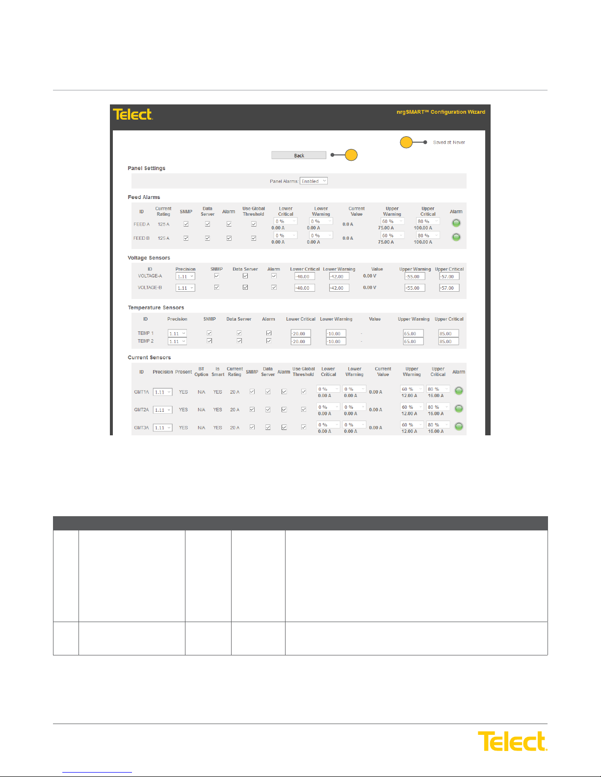
Figure 26 - Circuit Settings Window
NOTE: The Circuit Settings Window opens when the Advanced button is selected while in the Circuit Confi guration Screen. This window
contains Panel Settings, Breaker Alarms, Voltage Sensors, Temperature Sensors and Current Sensors Screens.
Panels Tab :: Circuit Confi guration > Circuit Settings Window
Ref. Field Type Value Description
1 Saved At Read Only Text The latest date and time that information in this window was saved.
NOTE: When a fi eld is updated within the Circuit Settings Window,
clicking outside of the fi eld saves the information and updates the Saved
At time.
Field settings are:
Never: Data not saved
Date/Time: mm/dd/yyyy HH:MM:SS (AM/ PM)
2 Back Select Button Return to the
Select the Back button to return to the
Circuit Confi guration Screen
Circuit Confi guration Screen
.
.
© Telect, Inc. All rights reserved. 3.22.17 v.3
1.509.926.6000 :: telect.com
41
Page 42
nrgSMART
nrgSMART
™
Controller Confi guration Guide
POWER ::
User Guide
™
Controller Confi guration Guide
POWER ::
User Guide
1
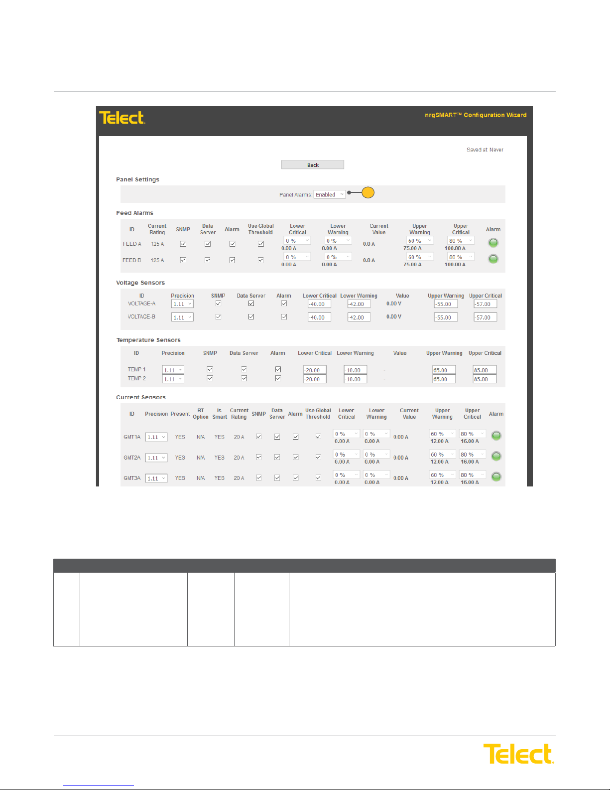
Panels Tab :: Circuit Confi guration > Circuit Settings > Panel Settings Screen
Ref. Field Type Value Description
1 Panel Alarms Select Drop down
© Telect, Inc. All rights reserved. 3.22.17 v.3
1.509.926.6000 :: telect.com
Figure 27 - Panels Settings Screen
This setting allows panel data to display pertaining to breaker alarms,
menu
voltage sensors, temperature sensors and current sensors.
Default is: Enabled
From the Panel Alarms drop down menu, select Enabled to allow panel
data to display. Select Disabled to prevent panel data displays.
42
Page 43
nrgSMART
nrgSMART
™
Controller Confi guration Guide
POWER ::
User Guide
™
Controller Confi guration Guide
POWER ::
1
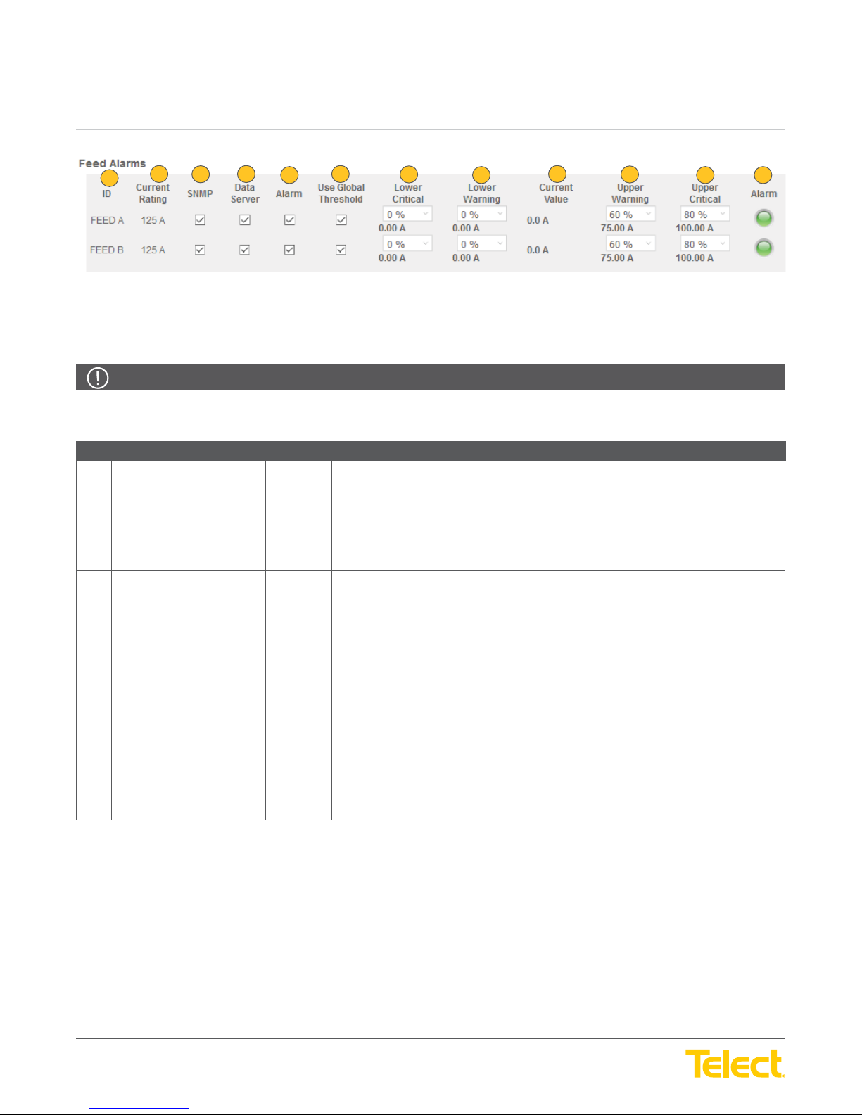
For data to display in the
NOTE: Field values in this screen default to specifi c settings. They do not require additional input, but can be customized if desired.
The fi elds in this table are column headings that defi ne data displayed in rows within the columns.
User Guide
2
3
Feed Alarms Screen
4
5
6
, select Enabled in the
7
Figure 28 - Feed Alarms Screen
8
Panels Screen
9
.
10
11 12
ALERT
ALERT! Light indicators for these fi elds ONLY display in this screen as notifi cation of breaker status.
Panels Tab :: Circuit Confi guration > Circuit Settings > Breaker Alarms Screen
Ref. Field Type Value Description
1 ID Read Only Text The row for the Feed.
2 Current Rating Read Text Indicates the rating of the fuse or circuit breaker.
Default is: 20 A
When defi ned in the Circuit Confi guration Screen, the fi eld defaults to
that value.
3 SNMP Select Checkbox When SNMP is enabled (in the
status of the breaker alarm for SNMP and all associated traps to be sent
to the SNMP server.
Default is: Checked
To enable the breaker alarm status for SNMP to be sent, select (to
check) the SNMP Checkbox. To disable the alarm, deselect the
Checkbox.
NOTE: When this fi eld is enabled, a software setting showing the status
of the alarm can be sent. Threshold settings enabled during controller
confi guration remain operational even when this fi eld is unchecked and
the hardware will still display alarm notifi cations.
See the State fi eld (below) for light indicator settings.
4 Data Server Select Checkbox This feature has been removed.
Controller Tab
) this checkbox allows the
© Telect, Inc. All rights reserved. 3.22.17 v.3
1.509.926.6000 :: telect.com
43
Page 44
nrgSMART
nrgSMART
™
Controller Confi guration Guide
POWER ::
User Guide
™
Controller Confi guration Guide
POWER ::
Panels Tab :: Circuit Confi guration > Circuit Settings > Breaker Alarms Screen
Ref. Field Type Value Description
5 Alarm Select Checkbox The current sensor for the Alarm allows the alarm status to be sent
6 Use Global Threshold Select Checkbox A percentage of a circuit’s breaker range or fuse range as the threshold
7 Lower Critical Select Drop down
User Guide
Menu
to SNMP. This fi eld also determines the availability of the Use Global
Threshold checkbox. When the Alarm checkbox is selected, the option to
use predetermined global threshold settings or change global threshold
settings is available. If the Alarm checkbox is not selected, the option to
change global threshold settings is not available.
Default: Checked
To enable the Alarm current sensor status to be sent and to allow global
threshold settings to be adjusted, select (to check) the Alarm Checkbox.
To disable, deselect the Checkbox.
Note: When unchecked, the Global Threshold Settings checkbox is
not accessible. See Global Threshold Settings (Lower Critical, Lower
Warning, Current Value, Upper Warning and Upper Critical) and the
Alarm (light) fi elds below for indicator settings.
value for alarms.
The following fi elds allow threshold values to be set to indicate lower or
higher than normally expected current ranges.
Lower Critical is a user defi ned threshold that is a percentage of the
Global Fuse Rating and indicates a lower than expected measurement,
defi ned as a critical alarm.
Default is: 0%
From the Lower Critical drop down menu, select from: 0% to 100% in
5% increments.
8 Lower Warning Select Drop down
Menu
9 Current Value Read Only Text Indicates the measured amount of current going into the equipment.
10 Upper Warning Select Drop down
Menu
Lower Warning is a user defi ned threshold that is a percentage of the
Global Fuse Rating and indicates a lower than expected measurement,
defi ned as a warning alarm.
Default is: 0%
From the Lower Warning drop down menu, select from: 0% to 100% in
5% increments.
Displays as amperage.
Upper Warning is user defi ned threshold that is a percentage of the
Global Fuse Rating and indicates a higher than expected measurement,
defi ned as a warning alarm.
Default is: 60%
From the Upper Warning drop down menu, select from: 0% to 100% in
5% increments.
© Telect, Inc. All rights reserved. 3.22.17 v.3
1.509.926.6000 :: telect.com
44
Page 45
nrgSMART
nrgSMART
™
Controller Confi guration Guide
POWER ::
User Guide
™
Controller Confi guration Guide
POWER ::
Controller Tab :: Measurement Settings Screen
Ref. Field Type Value Description
11 Upper Critical Select Drop down
12 Alarm Read Only Light This light indicates the threshold level of current to the circuit on the row.
User Guide
menu
Upper Critical is a user defi ned threshold that is a percentage of the Global
Fuse Rating and indicates a higher than expected measurement, defi ned
as a critical alarm.
Default is: 80%
From the Upper Critical drop down menu, select from: 0% to 100% in
5% increments.
Green: Normal current.
Yellow: Warning threshold reached.
Orange: Critical threshold reached.
Red: A blown fuse or tripped breaker.
Gray: Not connected.
© Telect, Inc. All rights reserved. 3.22.17 v.3
1.509.926.6000 :: telect.com
45
Page 46
nrgSMART
nrgSMART
™
Controller Confi guration Guide
POWER ::
User Guide
™
Controller Confi guration Guide
POWER ::
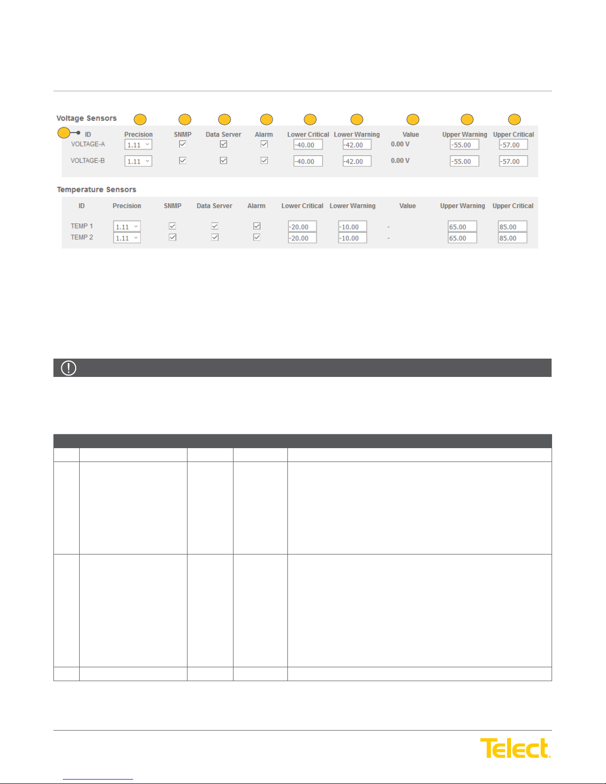
1
For data to display in the
NOTE: Field values in these screens default to specifi c settings. They do not require additional input, but can be customized if desired.
The fi elds in these tables are column headings that defi ne data displayed in rows within the columns.
User Guide
2 103 4 5 6 7
Figure 29 - Voltage Sensors Screen and Temperature Sensors Screen
Voltage Sensors and the Temperature Sensors Screens
8
, select Enabled in the
Panels Screen
9
.
ALERT
ALERT! Unless otherwise noted, fi eld settings are defi ned in the same manner for the
Sensors Screen
Panels Tab :: Circuit Confi guration > Circuit Settings > Voltage Sensors and Temperature Sensors Screens
Ref. Field Type Value Description
1 ID (column) Read Only Text The row for the sensor settings being defi ned.
2 Precision (column) Select Drop down
3 SNMP (column) Select Checkbox When SNMP is enabled (in the
4 Data Server (column) Select Checkbox This feature has been removed.
. Indicators for these fi elds ONLY display in this screen as notifi cation of sensor settings.
Sets the current sensor precision value for the selected row. This value
Menu
determines the amount of fl uctuation before a sensor adjusts its reading.
Default is: 1.11
From the Precision drop down menu, select from:
1.xx: This value can fl uctuate by one point before a sensor adjusts.
1.1x: This value can fl uctuate by 1/10 of a point before a sensor adjusts.
1.11: This value can fl uctuate by 1/100 of a point before a sensor adjusts.
voltage or temperature sensor data to be sent over SNMP.
Default is: Checked
To enable sensor settings for SNMP, select (to check) the SNMP
Checkbox. To disable, deselect the Checkbox.
NOTE: Threshold settings enabled during controller confi guration remain
operational even when this fi eld is unchecked, but sensor settings are
not set.
Voltage Sensors Screen
Controller Tab
and the
), this checkbox allows the
Temperature
© Telect, Inc. All rights reserved. 3.22.17 v.3
1.509.926.6000 :: telect.com
46
Page 47
nrgSMART
nrgSMART
™
Controller Confi guration Guide
POWER ::
User Guide
™
Controller Confi guration Guide
POWER ::
Panels Tab :: Circuit Confi guration > Circuit Settings > Voltage Sensors and Temperature Sensors Screens
Ref. Field Type Value Description
5 Alarm (column) Select Checkbox This checkbox allows the voltage or temperature sensor for the Alarm
6 Lower Critical (column) Input Text Lower Critical is a user defi ned threshold that indicates a much lower
7 Lower Warning (column) Input Text Lower Warning is a user defi ned threshold that indicates a lower than
User Guide
state to send alarm data over SNMP.
Default is: Checked
To enable sensor settings for the Alarm to be sent, select (to check) the
Alarm Checkbox. To disable, deselect the Checkbox.
NOTE: Threshold settings enabled during controller confi guration remain
operational even when this fi eld is unchecked, but sensor settings are
not set.
The Alarm sensor allows sensor alarms in the following fi elds. When this
fi eld is disabled, no threshold alarms display for the row.
than expected value.
Voltage Default is: -40.00
Temperature Default is: -20.00
Enter a range to indicate the Lower Critical sensor threshold.
expected value.
Voltage Default is: -42.00
Temperature Default is: -10.00
Enter a range to indicate the Lower Warning sensor threshold.
8 Value (column) Read Only Text Measured value.
No Voltage Default is: 0.00
No Temperature Default is: 9 Upper Warning (column) Input Text Upper Warning is a user defi ned threshold that indicates a higher than
expected value.
Voltage Default is: -55.00
Temperature Default is: -65.00
Enter a range to indicate the Upper Warning sensor threshold.
10 Upper Critical (column) Input Text Upper Critical is a user defi ned threshold that indicates a much higher
than expected value.
Voltage Default is: -57.00
Temperature Default is: -85.00
Enter a range to indicate the Upper Critical sensor threshold.
© Telect, Inc. All rights reserved. 3.22.17 v.3
1.509.926.6000 :: telect.com
47
Page 48
nrgSMART
nrgSMART
™
Controller Confi guration Guide
POWER ::
User Guide
™
Controller Confi guration Guide
POWER ::
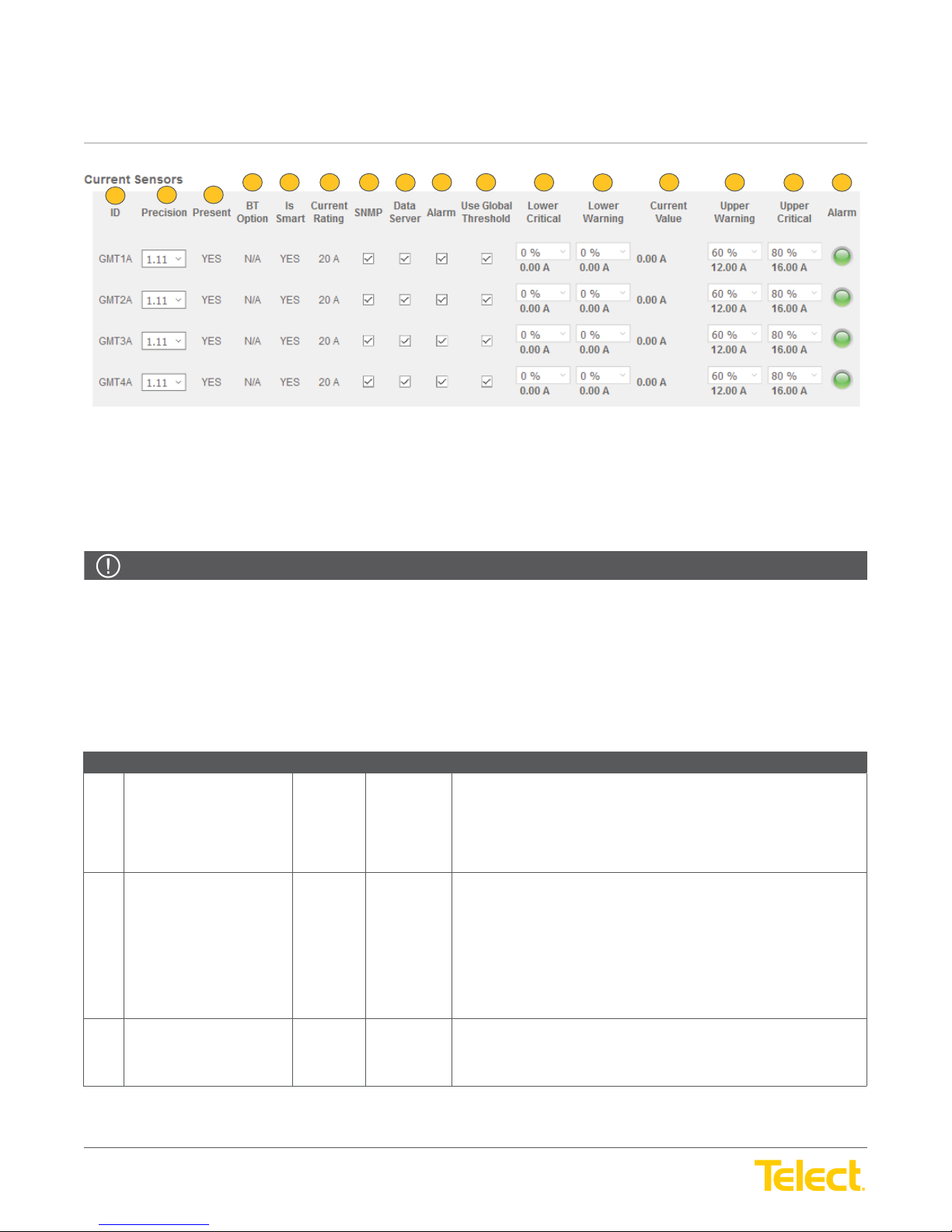
1
For data to display in the
NOTE: Field values in this screen default to specifi c settings. They do not require additional input, but can be customized if desired.
The fi elds in this table are column headings that defi ne data displayed in rows within the columns.
User Guide
2
3
Current Sensors Screen
6
8 16
, select Enabled in the
104 5 7 9 11
Figure 30 - Current Sensors Screen
Panels Screen
12
.
13
14
15
ALERT
ALERT! Global Threshold and light indicators for these fi elds will ONLY display in this screen.
The
Current Sensors Screen
can be adjusted to refl ect the degree of fl uctuation in current. When enabled, global threshold values indicate where current levels are among
one or both selected SNMP and Alarm sensors. The Alarm light displays the highest threshold value in the row depending on selection of one
or both selected SNMP and Alarm sensors.
Panels Tab :: Circuit Confi guration > Circuit Settings > Current Sensors Screen
Ref. Field Type Value Description
1 ID (column) Read Only Text Indicates the fuse type and its location in the panel.
2 Precision (column) Select Drop down
3 Present (column) Read Only Text Indicates if a sensor module is in the location indicated in the ID column.
is a tool to view how circuits are performing using sensors that indicate current status. Sensor precision values
Circuit outputs can include: Single-Pole Output, Dual-Pole Output,
Triple-Pole Output, GMT, TPS and TLS.
Menu
Refer to 6.2,
Sets the Current Sensor precision value for the selected row. This value
determines the amount of fl uctuation before a sensor adjusts its reading.
Default is: 1.11
From the Precision drop down menu, select from:
1.xx: This value can fl uctuate by one point before a sensor adjusts.
1.1x: This value can fl uctuate by 1/10 of a point before a sensor adjusts.
1.11: This value can fl uctuate by 1/100 of a point before a sensor adjusts.
Fuse/Circuit Breaker Ratings
for more information.
© Telect, Inc. All rights reserved. 3.22.17 v.3
1.509.926.6000 :: telect.com
Default is: No
When the sensor module has been added, this fi eld defaults to Yes.
48
Page 49
nrgSMART
nrgSMART
™
Controller Confi guration Guide
POWER ::
User Guide
™
Controller Confi guration Guide
POWER ::
Panels Tab :: Circuit Confi guration > Circuit Settings > Current Sensors Screen
Ref. Field Type Value Description
4 BT Option (column) Read Only Text Indicates if a bullet terminal has been selected at the selected location.
5 Is Smart (column) Read Only Text Indicates the presence of a monitoring sensor.
6 Current Rating (column) Read Only Text Indicates the rating of the fuse or circuit breaker.
7 SNMP (column) Select Checkbox When SNMP is enabled (in the
User Guide
Default is: N/A, No selection
When there is a bullet terminal sensor present, this fi eld defaults to Yes.
Default is: No, indicating a pass through module that does not monitor.
When a monitoring sensor is installed, this fi eld defaults to Yes.
Default is: 20 A
When defi ned in the
that value.
SNMP checkbox allows the current status to be sent.
Default is: Checked
To enable the SNMP current sensor status to be sent over SNMP, select
(to check) the SNMP Checkbox. To disable the alarm, deselect the
Checkbox.
Circuit Confi guration Screen
Controller Tab
) the current sensor for
, the fi eld defaults to
NOTE: When this fi eld is enabled, a software setting showing the status
of the alarm can be sent. Threshold settings enabled during controller
confi guration remain operational even when this fi eld is unchecked.
See Global Threshold Settings (Lower Critical, Lower Warning, Current
Value, Upper Warning and Upper Critical) and the Alarm (light) fi elds
below for indicator settings.
8 Data Server (column) Select Checkbox This feature has been removed.
© Telect, Inc. All rights reserved. 3.22.17 v.3
1.509.926.6000 :: telect.com
49
Page 50
nrgSMART
nrgSMART
™
Controller Confi guration Guide
POWER ::
User Guide
™
Controller Confi guration Guide
POWER ::
Panels Tab :: Circuit Confi guration > Circuit Settings > Current Sensors Screen
Ref. Field Type Value Description
9 Alarm (column) Select Checkbox The current sensor for the Alarm allows the alarm status to be sent to
10 Use Global Threshold Select Checkbox Allows predetermined global threshold settings to be used in detecting
User Guide
SNMP.
This fi eld also determines the availability of the Use Global Threshold
checkbox. When the Alarm checkbox is selected, the option to use
predetermined global threshold settings or change global threshold
settings is available. If the Alarm checkbox is not selected, the option to
change global threshold settings is not available.
Default is: Checked
To enable the Alarm current sensor status to be sent and to allow global
threshold settings to be adjusted, select (to check) the Alarm Checkbox.
To disable, deselect the Checkbox.
NOTE: When unchecked, the Global Threshold Settings checkbox is
not accessible.
See Global Threshold Settings (Lower Critical, Lower Warning, Current
Value, Upper Warning and Upper Critical) and the Alarm (light) fi elds
below for indicator settings.
current sensor status at the selected location or to adjust settings in
this screen.
11 Lower Critical (column) Select Drop down
Menu
Default is: Checked to use predetermined global threshold settings.
NOTE: The current sensor Alarm checkbox must be checked for this fi eld
to allow input.
To use predetermined global threshold settings, select (to check) the
Use Global Threshold Checkbox. To adjust global threshold settings in
this screen, deselect the Checkbox.
When the Use Global Threshold Checkbox is not selected, threshold
values can be changed in the Lower Critical, Lower Warning, Upper
Warning and Upper Critical fi elds below. The Current Value fi eld refl ects
the value of the current and is read only.
Lower Critical is a user defi ned threshold that indicates a much lower
than expected value.
The number below the percentage setting displays the current value that
the circuit will be at if the lower critical threshold is reached.
Default is: 0% and current value is 0.00 A
NOTE: The Use Global Threshold checkbox must be unchecked to
change a value.
From the Lower Critical drop down menu select a percentage of the fuse
rating to indicate the lower critical sensor threshold. Select from 0% to
100% in 5% increments.
© Telect, Inc. All rights reserved. 3.22.17 v.3
1.509.926.6000 :: telect.com
50
Page 51
nrgSMART
nrgSMART
™
Controller Confi guration Guide
POWER ::
User Guide
™
Controller Confi guration Guide
POWER ::
Panels Tab :: Circuit Confi guration > Circuit Settings > Current Sensors Screen
Ref. Field Type Value Description
12 Lower Warning (column) Input Drop down
13 Current Value (column) Read Only Text Measured value.
14 Upper Warning (column) Select Drop down
User Guide
Menu
Menu
Lower Warning is a user defi ned threshold that indicates a lower than
expected value.
The number below the percentage setting displays the current value that
the circuit will be at if the lower warning threshold is reached.
Default is: 0% and current value is 0.00 A
NOTE: The Use Global Threshold checkbox must be unchecked to
change a value.
From the Lower Warning drop down menu, select a percentage of the
fuse rating to indicate the lower warning sensor threshold. Select from
0% to 100% in 5% increments.
Upper Warning is a user defi ned threshold that indicates a higher than
expected value.
The number below the percentage setting displays the current value that
the circuit will be at if the upper warning threshold is reached.
Default is: 60% and current value is 12.00 A of 20 AMP
NOTE: The Use Global Threshold checkbox must be unchecked to
change a value.
From the Upper Warning drop down menu, select a percentage of the
fuse rating to indicate the upper warning sensor threshold. Select from
0% to 100% in 5% increments.
15 Upper Critical (column) Select Drop down
Menu
16 Alarm Read Only Light Indicates the most elevated status of the selected sensors at the
Upper Critical is a user defi ned threshold that indicates a much higher
than expected value.
The number below the percentage setting displays the current value that
the circuit will be at if the upper critical threshold is reached.
Default is: 80% and current value is 16.00 A of 20 AMP
NOTE: The Use Global Threshold checkbox must be unchecked to
change a value.
From the Upper Critical drop down menu, select a percentage of the fuse
rating to indicate the upper critical sensor threshold. Select from 0% to
100% in 5% increments.
selected location according to global threshold values (shown in this
screen).
This light indicates the breaker and threshold alarm status for the
individual circuit.
Green: Normal current.
Yellow: Warning threshold reached.
Orange: Critical threshold reached.
Red: A blown fuse or tripped breaker.
Gray: Not connected.
© Telect, Inc. All rights reserved. 3.22.17 v.3
1.509.926.6000 :: telect.com
51
Page 52
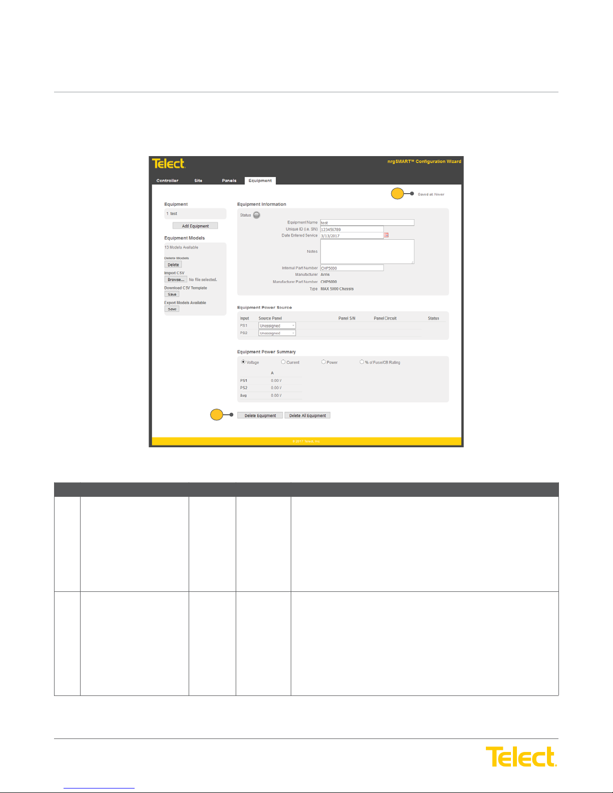
nrgSMART
nrgSMART
™
Controller Confi guration Guide
POWER ::
User Guide
™
Controller Confi guration Guide
POWER ::
User Guide
5. Equipment Tab Settings
The
Equipment Tab
equipment or assign equipment input labels to specifi c PDU circuit locations.
is comprised of the main window (
Equipment Tab Window
) and screens that display information pertaining to associated
1
2
Figure 31 - Equipment Tab Window
Equipment Tab Window
Ref. Field Type Value Description
1 Saved At Read Only Text The date the information in the
NOTE: When a fi eld is updated within a screen in the Equipment Tab,
clicking outside of the fi eld saves the information and updates the Saved
At time.
Field settings are:
Never: Data not saved
Date/Time: mm/dd/yyyy HH:MM:SS (AM/PM)
2 Delete Equipment Select Button Removes the selected equipment and all of the associated information
from the
Select the Delete Equipment button to remove the selected equipment
and associated information from the
is deleted, the rows below the Equipment Name row in the
Screen
NOTE: This button deletes information from the Equipment Tab, not the
equipment model.
Equipment Tab
shift up.
.
Equipment Tab
Equipment Tab
was last saved.
. When equipment
Equipment
© Telect, Inc. All rights reserved. 3.22.17 v.3
1.509.926.6000 :: telect.com
52
Page 53
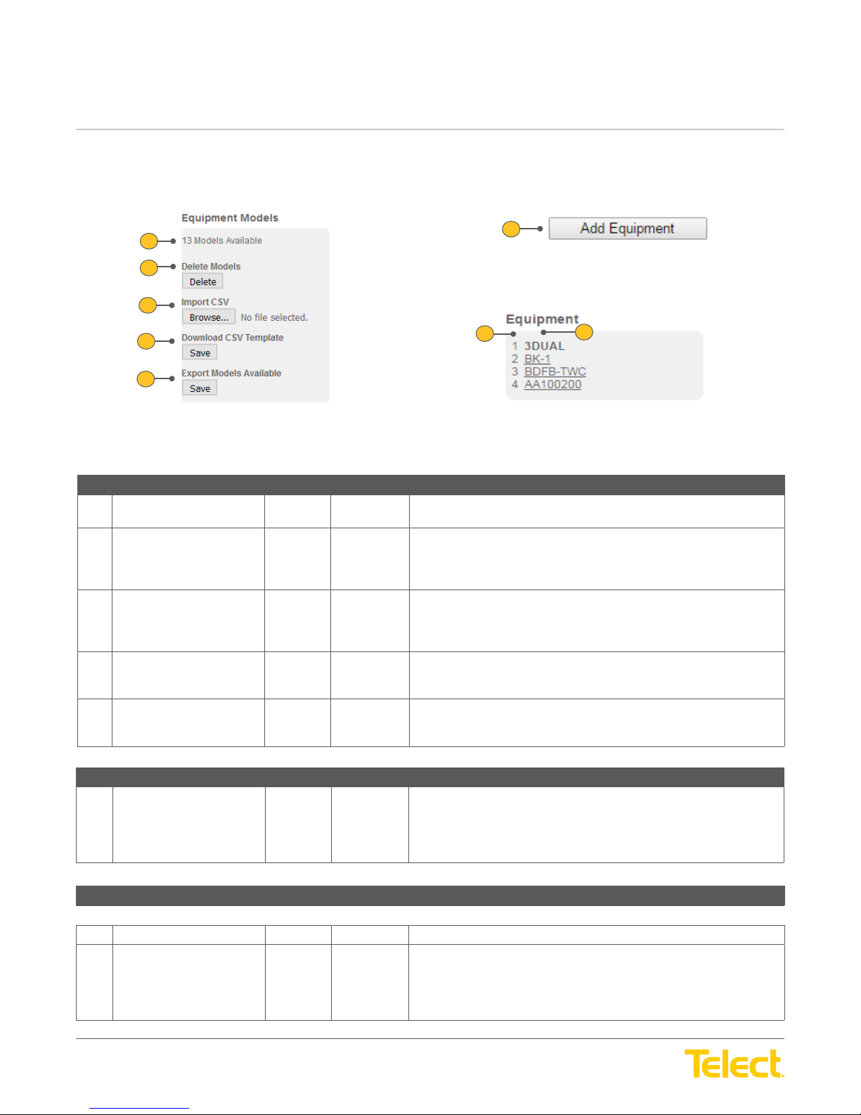
nrgSMART
nrgSMART
™
Controller Confi guration Guide
POWER ::
User Guide
™
Controller Confi guration Guide
POWER ::
Take the following steps to view and monitor equipment in the
1. See page 61-62 on importing and adding new equipment.
Equipment Tab :: Equipment Models Screen
Ref. Field Type Value Description
1 Models Available Read Only Text Displays equipment model list, with a number of equipment models to
2 Delete Models Select Button Removes all models in equipment list. Select the Delete button to
3 Import CSV Template Select Button Download a pre-defi ned equipment model list containing the equipment
4 Download CSV Template Select Button Download a pre-defi ned equipment model list containing the equipment
5 Export Models Available Select Button Exports a list of equipment models associated with the controller. Select
Equipment Tab :: Add Equipment button
Ref. Field Type Value Description
6 Add Equipment Select Button Opens the
User Guide
1
2
3
4
5
Equipment Tab
Figure 32 - Equipment Models, Add Equipment and Equipment
choose from, for defi ning a unique equipment instance.
remove the selected panel and associated information from the
Panels Tab.
Note: This will remove all models.
models that you have entered in the CVS fi le.
Select the Browse button to select a fi le to import. Select Open to import
the fi le. The fi le name displays in the Models Available fi eld.
models to choose from. Select the Save button to select the fi le location
to save in. Select Open to save the fi le.
the Equipment Model containing the list of equipment you wish to export.
Select the Save button to export the fi le.
can be defi ned and added to the
:
2. Select the Add Equipment button and choose the equipment to
add in the
3. Highlight an equipment name in the
information and monitor power settings in the
New Equipment Information Screen
6
7
New Equipment Information Screen
8
Equipment Screen
.
Equipment Screen
Equipment Tab
where new equipment
.
to view
.
Equipment Tab :: Equipment Screen
Ref. Field Type Value Description
NOTE: The fi elds below are column headings that defi ne data displayed in rows within the columns.
7 Number (column) Read Only Text The row number for the equipment named.
8 Equipment Name (column) Select Text The Equipment Name identifi es the equipment.
© Telect, Inc. All rights reserved. 3.22.17 v.3
1.509.926.6000 :: telect.com
Select the Add Equipment button to defi ne additional equipment in the
New Equipment Information Window.
Highlight a name to select equipment to view and monitor. When
selected, the Equipment Name becomes bold and associated fi elds
populate the screens in the
53
Equipment Tab
.
Page 54
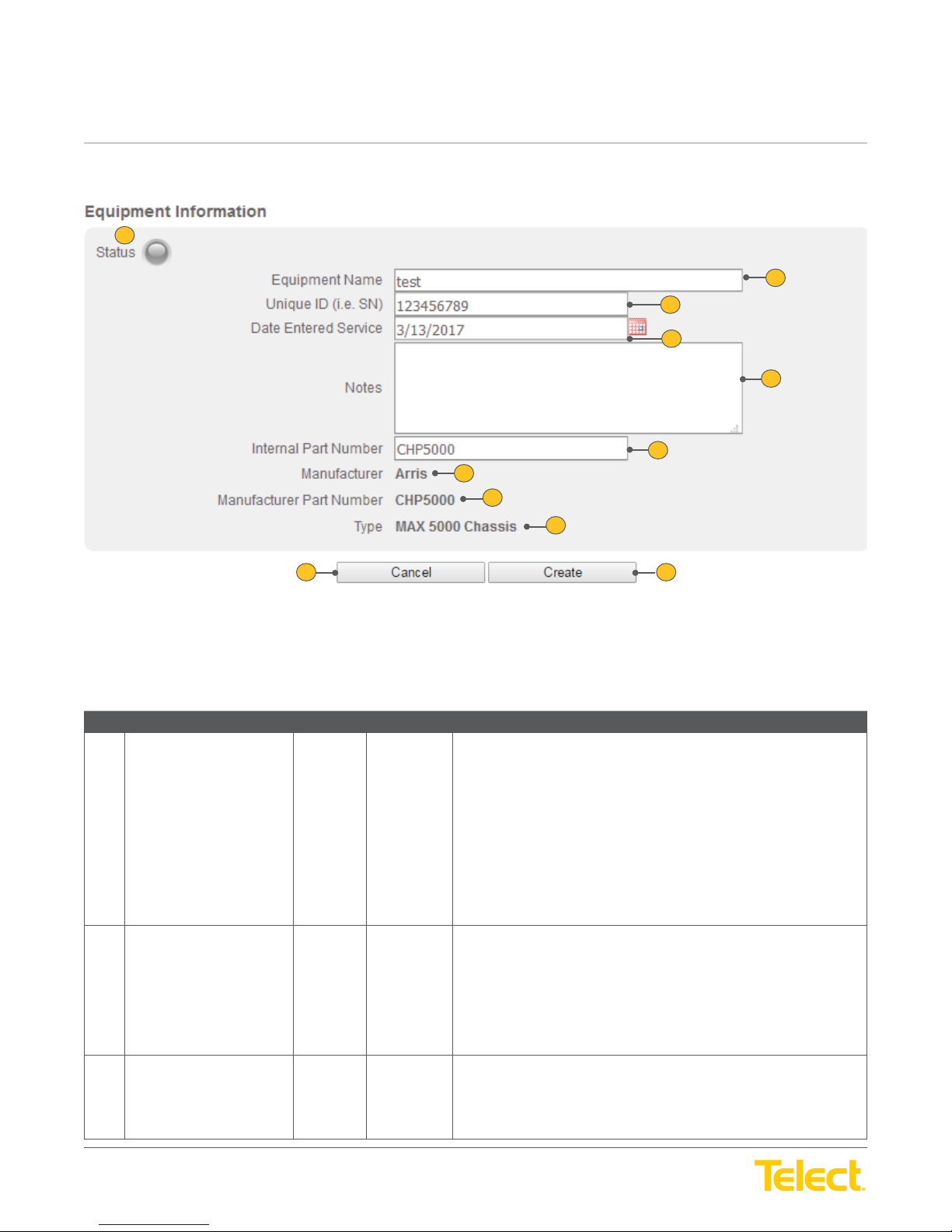
nrgSMART
nrgSMART
™
Controller Confi guration Guide
POWER ::
User Guide
™
Controller Confi guration Guide
POWER ::
1
User Guide
10 11
2
3
4
5
6
7
8
9
Figure 33 - New Equipment Information Window/Equipment Information Screen
Defi ne equipment in the
information displays in screens in the
Equipment Tab :: New Equipment Information Window/Equipment Information Screen
Ref. Field Type Value Description
1 Status Light Read Only Light
2 Equipment Name Input Text Name of the equipment whose information is defi ned or displays in
3 Equipment Serial Number Input Text The Serial Number shown on the equipment.
New Equipment Information Window
Equipment Tab
and select the Create button at the bottom. The newly created equipment
.
NOTE: The status light does not display in the New Equipment
Information Window. It only displays in the Equipment Information Screen
after equipment has been added.
Located in the upper corner of the
Status light summarizes the operating state of the equipment.
Green: Normal operation.
Yellow: Warning threshold reached.
Orange: Critical threshold reached.
Red: A blown fuse or tripped breaker.
Gray: Not connected.
this screen.
Enter an equipment name to add new equipment information (
Equipment Information Window
information, enter a different valid Equipment Name in this fi eld. This
fi eld accepts up to 40 characters. Valid characters are upper/lowercase
letters, numbers, symbols and spaces.
Equipment Information Screen
) or to view or modify other equipment
New
, the
© Telect, Inc. All rights reserved. 3.22.17 v.3
1.509.926.6000 :: telect.com
Enter the Serial Number when adding new equipment, or view or modify
existing information. Valid characters are upper/lowercase letters,
numbers, symbols and spaces.
54
Page 55
nrgSMART
nrgSMART
™
Controller Confi guration Guide
POWER ::
User Guide
™
Controller Confi guration Guide
POWER ::
Equipment Tab :: New Equipment Information Window/Equipment Information Screen
Ref. Field Type Value Description
4 Date Entered Service Input Text The date that the equipment is connected and is operational.
5 Notes Input Text Add additional information specifi c to this equipment.
6 Internal Part Number Select Drop down The internal part number assigned to the equipment by the
7 Manufacturer Read Only Text The name of the equipment manufacturer.
8 Manufacturer Part Number Read Only Text The part number assigned to the equipment by the manufacturer.
9 Type Read Only Text Identifi es the kind of equipment.
10 Cancel Select Button
User Guide
Default is: Current date, displays as mm/dd/yyyy, indicating the date the
equipment is added.
To change this setting, enter a new date or click on the calendar and
make a selection.
Enter any notes or additional information pertaining to this equipment.
Valid characters are upper/lowercase letters, numbers, symbols and
spaces.
equipment model.
View the internal part number or change it by selecting the Internal Part
Number drop down menu and selecting the internal part number to
assign to the equipment.
The internal part number automatically populates the following fi elds
from the model defi nition.
NOTE: The Cancel button only displays in the New Equipment
Information Window.
11 Create Select Button
Returns to the
Select the Cancel button to remove this information and close the
Equipment Information Window
NOTE: The Create button only displays in the New Equipment
Information Window.
Adds the new equipment and returns to the
To add the new equipment, select the Create button. The new name will
display in the
Equipment Tab
Equipment Information Screen.
without adding the new equipment.
.
Equipment Tab
New
.
© Telect, Inc. All rights reserved. 3.22.17 v.3
1.509.926.6000 :: telect.com
55
Page 56
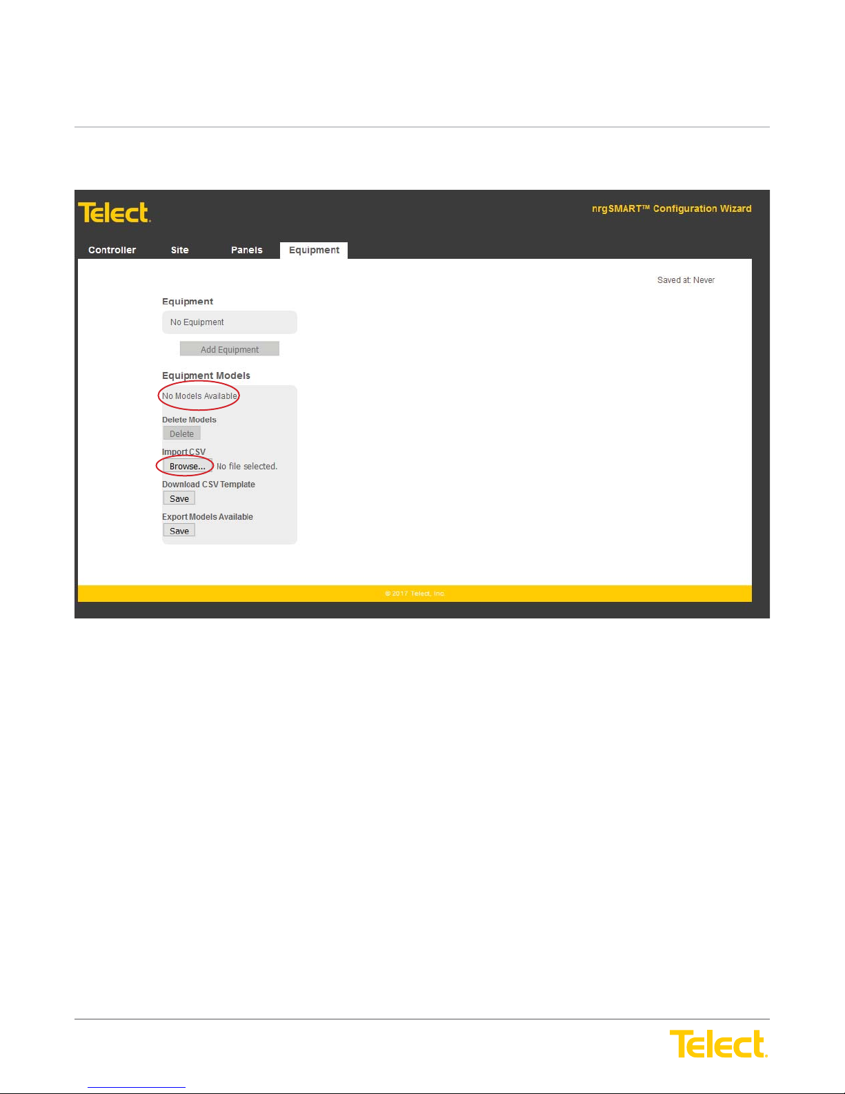
nrgSMART
nrgSMART
™
Controller Confi guration Guide
POWER ::
User Guide
™
Controller Confi guration Guide
POWER ::
5.1 Importing CSV and Adding Equipment
User Guide
No models available to add equipment. Select browse to import CSV fi le with equipment models
you would like to add.
© Telect, Inc. All rights reserved. 3.22.17 v.3
1.509.926.6000 :: telect.com
56
Page 57
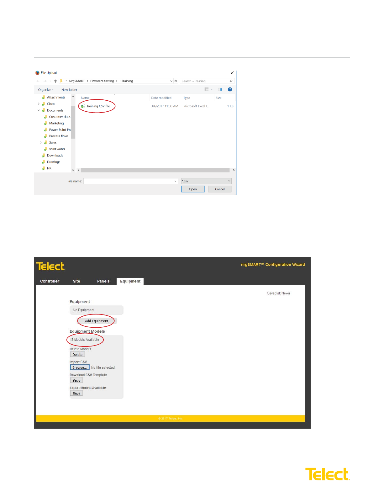
nrgSMART
nrgSMART
™
Controller Confi guration Guide
POWER ::
User Guide
™
Controller Confi guration Guide
POWER ::
Select the CSV fi le you would like to import.
User Guide
This screen shows that you have imported your CSV fi le correctly and you have 13 models available.
Select “Add Equipment” to install equipment attached to nrgSMART panels.
© Telect, Inc. All rights reserved. 3.22.17 v.3
1.509.926.6000 :: telect.com
57
Page 58
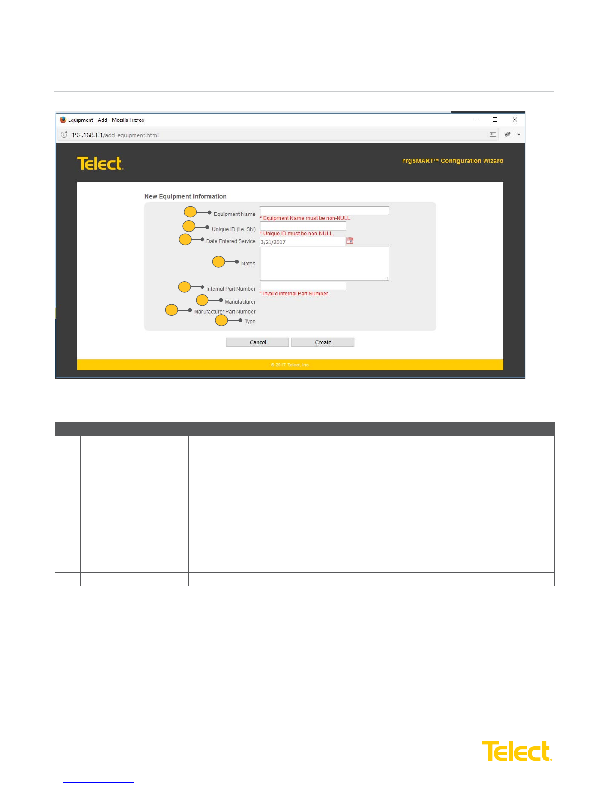
nrgSMART
nrgSMART
™
Controller Confi guration Guide
POWER ::
User Guide
™
Controller Confi guration Guide
POWER ::
User Guide
1
2
3
5
7
4
6
8
Equipment Tab :: New Equipment Information Window/Equipment Information Screen
Ref. Field Type Value Description
1 Equipment Name Input Text Name of the equipment whose information is defi ned or displays in
this screen.
Enter an equipment name to add new equipment information (
Equipment Information Window
information, enter a different valid Equipment Name in this fi eld. This
fi eld accepts up to 40 characters. Valid characters are upper/lowercase
letters, numbers, symbols and spaces.
2 Unique ID
(i.e.Serial Number)
3 Data Entered Service Input Text Insert date of when equipment was placed into service.
Input Text The Serial Number shown on the equipment.
Enter the Serial Number when adding new equipment, or view or modify
existing information. Valid characters are upper/lowercase letters,
numbers, symbols and spaces.
) or to view or modify other equipment
New
© Telect, Inc. All rights reserved. 3.22.17 v.3
1.509.926.6000 :: telect.com
58
Page 59
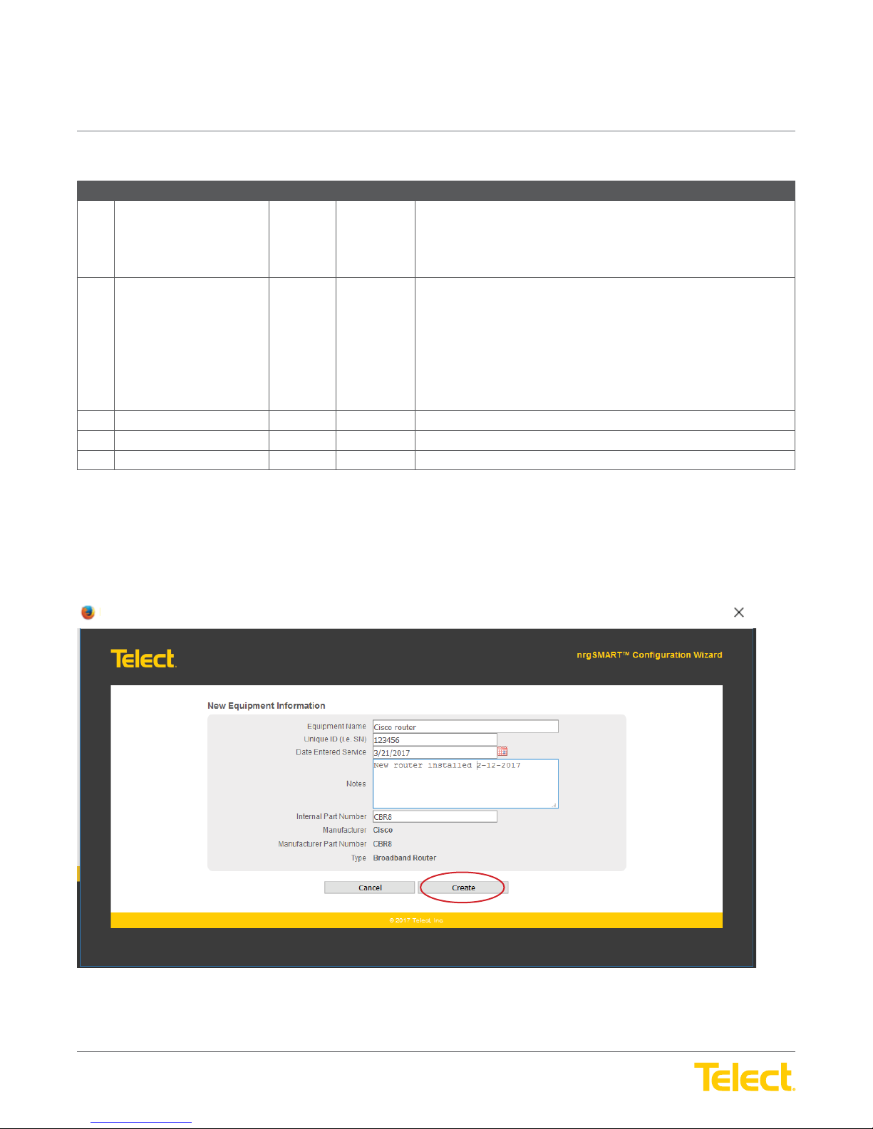
nrgSMART
nrgSMART
™
Controller Confi guration Guide
POWER ::
User Guide
™
Controller Confi guration Guide
POWER ::
Equipment Tab :: New Equipment Information Window/Equipment Information Screen
Ref. Field Type Value Description
4 Notes Input Text Add additional information specifi c to this equipment.
5 Internal Part Number Select Dropdown
6 Manufacturer Read Only Text The name of the equipment manufacturer.
7 Manufacturer Part Number Read Only Text The part number assigned to the equipment by the manufacturer.
8 Type Read Only Text Identifi es the kind of equipment.
User Guide
Menu
Enter any notes or additional information pertaining to this equipment.
Valid characters are upper/lowercase letters, numbers, symbols and
spaces.
The internal part number assigned to the equipment by the
equipment model.
View the internal part number or change it by selecting the Internal Part
Number drop down menu and selecting the internal part number to
assign to the equipment.
The internal part number automatically populates the following fi elds
from the model defi nition.
Once New Equipment Information form has been fi lled out, select “Create” to complete.
All fi elds in red must be completed.
© Telect, Inc. All rights reserved. 3.22.17 v.3
1.509.926.6000 :: telect.com
59
Page 60
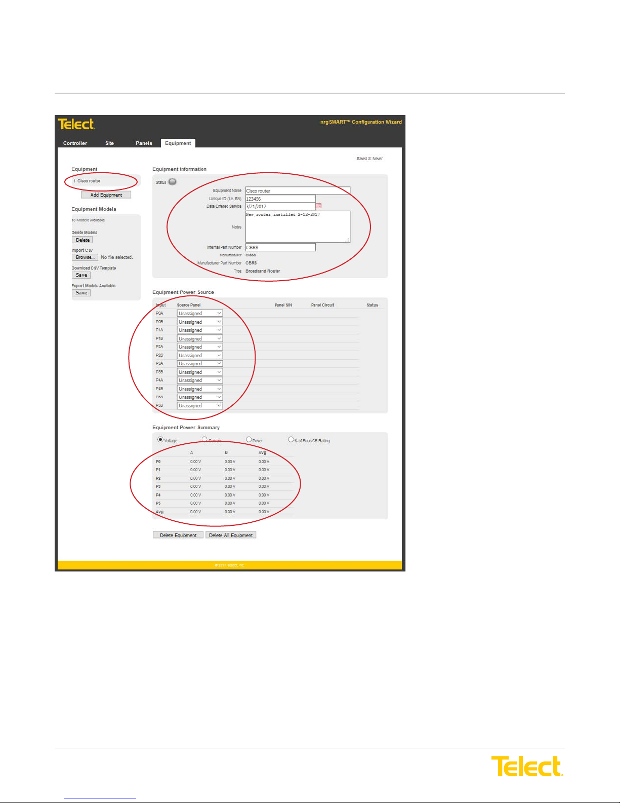
nrgSMART
nrgSMART
™
Controller Confi guration Guide
POWER ::
User Guide
™
Controller Confi guration Guide
POWER ::
User Guide
This screen shows newly added equipment and the populated fi elds associated to that hardware.
© Telect, Inc. All rights reserved. 3.22.17 v.3
1.509.926.6000 :: telect.com
60
Page 61
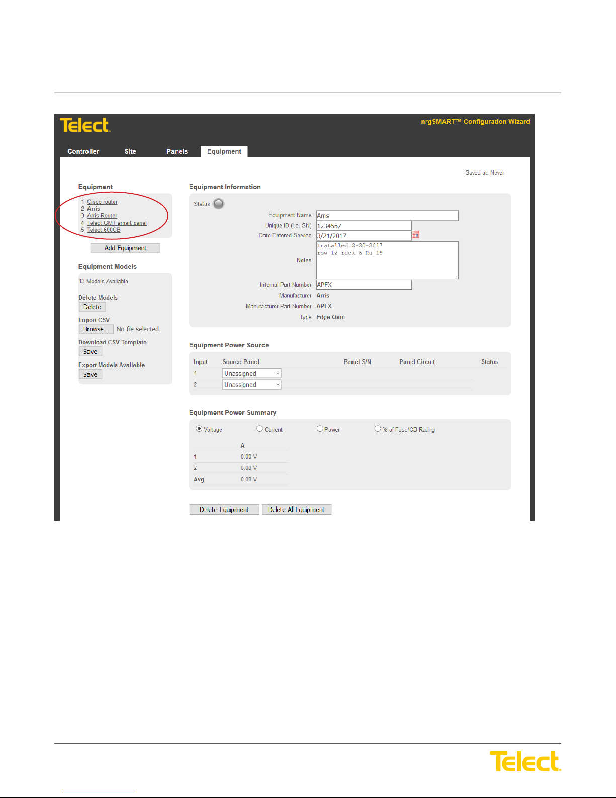
nrgSMART
nrgSMART
™
Controller Confi guration Guide
POWER ::
User Guide
™
Controller Confi guration Guide
POWER ::
User Guide
This screen shows several pieces of equipment that have been added.
© Telect, Inc. All rights reserved. 3.22.17 v.3
1.509.926.6000 :: telect.com
61
Page 62
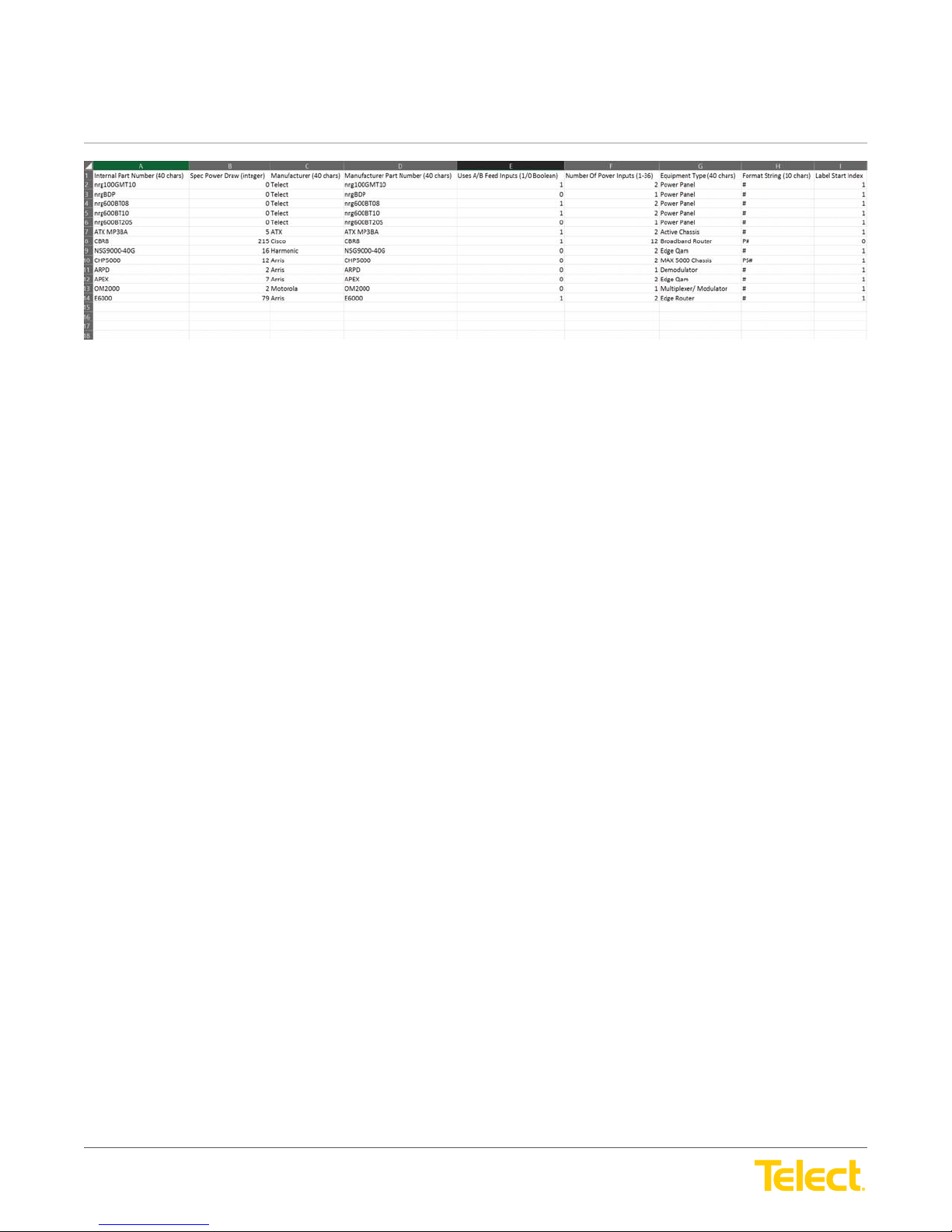
nrgSMART
nrgSMART
™
Controller Confi guration Guide
POWER ::
User Guide
™
Controller Confi guration Guide
POWER ::
Here is the CSV fi le that you will need to add your equipment to.
Note: Do not alter the format of this CSV fi le as it will not populate the fi elds correctly in the controller.
User Guide
.CSV FILE COLUMN DEFINITIONS
A. Internal part number (40 Characters): Quick Name or model number
B. Spec Power Draw (Integer): Use whole numbers in AMPS
C. Manufacturer (40 Characters): Place MFG name
D. Manufacturer Part Number (40 Characters): Place whole MFG part number
E. Uses A/B feed Inputs (1/0 Boolean): 1 for True A/B feeds - 0 for FALSE A/B feeds
(single feed)
F. Number of power inputs (1-36): Place number of power supplies per device
G. Equipment type (40 Characters): Type of power panel (GMT, TPA, Router etc.)
H. Format String (10 Characters): Format of power supplies naming convention by
Manufacturer (PS1 or PSM0 etc.)
I. Label start index: Starting position of power supply, either 0 or 1
Defi nitions of CSV fi elds above.
© Telect, Inc. All rights reserved. 3.22.17 v.3
1.509.926.6000 :: telect.com
62
Page 63
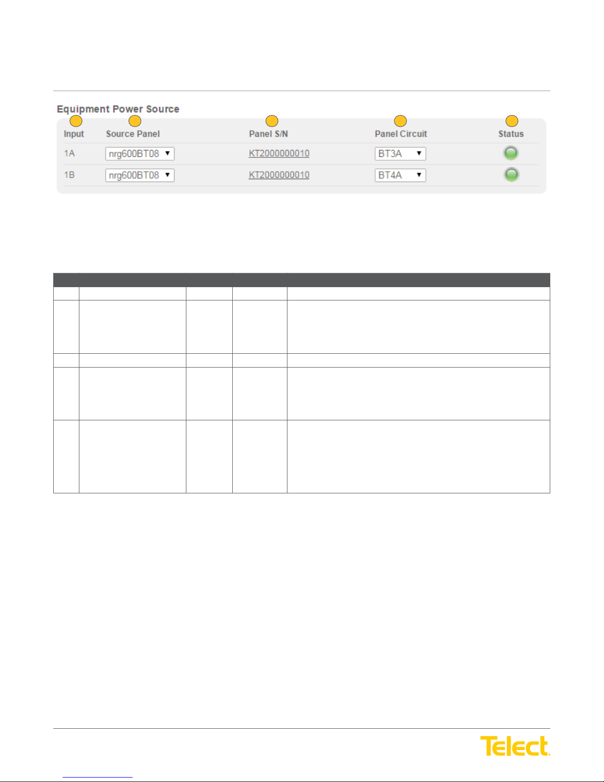
nrgSMART
nrgSMART
™
Controller Confi guration Guide
POWER ::
User Guide
™
Controller Confi guration Guide
POWER ::
1 2 3 4 5
NOTE: The fi elds in this table are column headings that defi ne data displayed in rows within the columns.
Equipment Tab :: Equipment Power Source Screen
Ref. Field Type Value Description
1 Input (column) Read Only Text Input description for the equipment in the row.
2 Source Panel (column) Select Drop down
3 Panel S/N (column) Read Only Text Displays the serial number for the selected source panel.
4 Panel Circuit (column) Select Drop down
5 Status (column) Read Only Light Indicates the overall status for the selected row.
User Guide
Figure 34 - Equipment Power Source Screen
Select the PDU panel for the equipment input.
menu
From the Source Panel drop down menu, select from:
Unassigned: no selection
List of available panels
Select the PDU panel circuit for the equipment input.
menu
From the Panel Circuit drop down menu, select from:
Unassigned: no selection
List of available circuits
Green: Normal operation.
Yellow: Warning threshold reached.
Orange: Critical threshold reached.
Red: A blown fuse or tripped breaker.
Gray: Not connected.
© Telect, Inc. All rights reserved. 3.22.17 v.3
1.509.926.6000 :: telect.com
63
Page 64
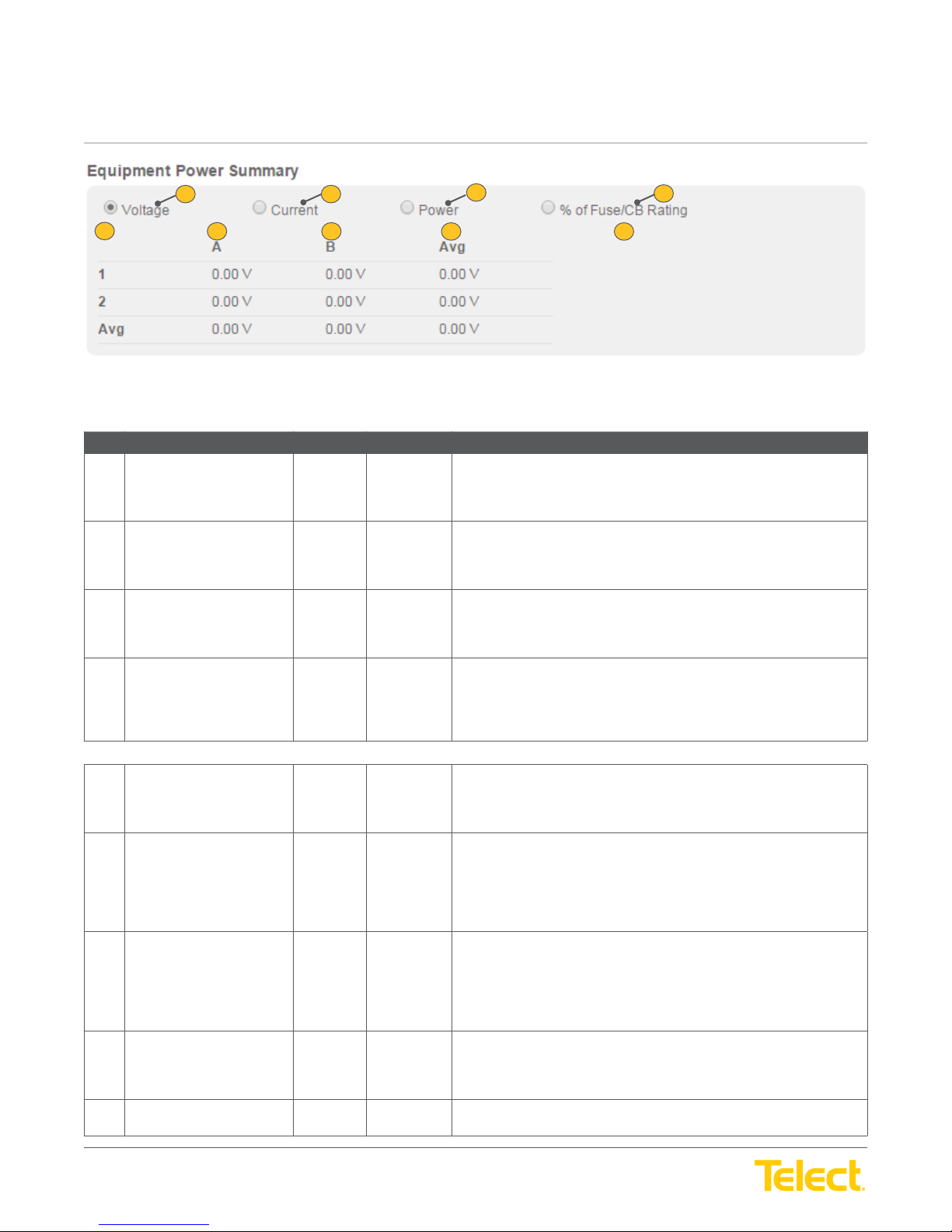
nrgSMART
nrgSMART
™
Controller Confi guration Guide
POWER ::
User Guide
™
Controller Confi guration Guide
POWER ::
5
Equipment Tab :: Equipment Power Summary Screen
Ref. Field Type Value Description
1 Voltage Select Button Selection of this button enables voltage readings for Feed A and Feed B
2 Current Select Button Selection of this button enables current readings for Feed A and Feed B
User Guide
1 2
6
3
7
Figure 36 - Equipment Power Summary Screen
8 9
and their averages to display in the following rows.
Select the Voltage button to display voltage readings.
and their averages to display in the following rows.
4
Select the Current button to display current readings.
3 Power Select Button Selection of this button enables power readings for Feed A and Feed B
and their averages to display in the following rows.
Select the Power button to display power readings.
4 % of Fuse/CB Rating Select Button Selection of this button enables the percentage of fuse or circuit breaker
in use to display for Feed A and Feed B in the following rows.
Select the % of Fuse/CB Rating button to display the percentage of the
fuse or circuit breaker that is in use for each row.
NOTE: The following fi elds are column headings that defi ne data displayed in rows within the columns.
5 Row # (column) Read Only Text The row identifi er.
NOTE: The last row (the Avg row) is an average of the total consumption
for that column.
6 A (column) Read Only Text Depending on the button selected at the top of the screen, this column
displays the settings for Feed A of this row.
V: voltage - measured in volts
C: current - measured in amps
W: power - measurement in kilowatts
7 B (column) Read Only Text Depending on the button selected at the top of the screen, this column
displays the settings for Feed B of this row.
V: voltage - units measured in volts
C: current - units measured in amps
W: power - measurement in kilowatts
8 Avg (column) Read Only Text Average of the measured value in columns A and B.
9 % Fuse/CB Rating (column) Read Only Text Displays the percentage of the fuse/circuit breaker in the row depending
© Telect, Inc. All rights reserved. 3.22.17 v.3
1.509.926.6000 :: telect.com
The button selected at the top of the screen determines which
unit displays.
on the rating for that device.
64
Page 65
nrgSMART
nrgSMART
™
Controller Confi guration Guide
POWER ::
User Guide
™
Controller Confi guration Guide
POWER ::
User Guide
6. Supplementary Information
6.1 MIB Table
Download Management Information Base Table at: http://support.telect.com/nrgSmart_HUB
6.2 Fuse/Circuit Breaker Ratings
Fuse/Circuit Breaker Rating
Amps
Singlepole
Doublepole*
Triplepole*
TFD
TPS
TFD
TLS
GMT
*multi-pole breaker only selectable if panel type allows multi-pole breakers
.18 .25 .5 .7511.33 1.522.533.5
X X X X X X X XXXXXXX X X
XXXXXXXXXXXXX
7.5
45
10 12 15 20 25 30 40 50 60 70 80 90 100 110 125 150 175 200 225 250
X X X XXXXXXX
X
X
XX
X
XX
X
XXX
XX
X
XX
Asymmetrical Breaker (nrgBDFB and nrg600BT08)
Standard Trip Circuit Breakers
Item Description Part Number Item Description Part Number
Single Pole 1A 118714 Double Pole 125A 134634
2A 119103 150A 134635
3A 124210 175A 135921
5A 117852 Triple Pole 200A 134636
10A 116669 225A 134637
15A 115999 250A 134638
20A 116670
25A 117402
30A 116671
40A 116672
50A 116673
60A 118160
70A 118161
80A 118162
90A 118163
100A 118159
© Telect, Inc. All rights reserved. 3.22.17 v.3
1.509.926.6000 :: telect.com
65
Page 66
nrgSMART
nrgSMART
™
Controller Confi guration Guide
POWER ::
User Guide
™
Controller Confi guration Guide
POWER ::
Instantaneous Trip Circuit Breakers
Item Description Part Number
Single Pole 20A 140368
User Guide
25A 140369
30A 140370
40A 140371
50A 140372
60A 140373
70A 140374
80A 140375
90A 140376
100A 140377
Symmetrical Breakers (nrg600BT10 and nrg600BT20S)
Standard Trip Circuit Breakers
Item Description Part Number Item Description Part Number
Single-Pole 5A 147604 Double-Pole 125A 148038
10A 147605 150A 148039
15A 147606 175A 148040
20A 147607 Triple-Pole 200A 148041
25A 147608 225A 148042
30A 147609 250A 148043
40A 147610
50A 147611
60A 147612
70A 147613
80A 147614
90A 147615
100A 147616
© Telect, Inc. All rights reserved. 3.22.17 v.3
1.509.926.6000 :: telect.com
66
Page 67
nrgSMART
nrgSMART
™
Controller Confi guration Guide
POWER ::
User Guide
™
Controller Confi guration Guide
POWER ::
TPS/TLS Fuses
These cannot be used in the nrg600BT10 or nrg600BT20S
Item Description Part Number
TFD Fuse Holder TPS/TLS Fuse Holder 129816
TPS Fuses 5A 130481
TLS Fuses 80A 140640
User Guide
10A 130485
15A 130487
20A 130489
25A 130476
30A 130478
40A 130482
50A 130484
60A 130486
70A 130488
90A 140641
100A 140642
110A 140643
125A 140644
© Telect, Inc. All rights reserved. 3.22.17 v.3
1.509.926.6000 :: telect.com
67
Page 68
nrgSMART
nrgSMART
™
Controller Confi guration Guide
POWER ::
User Guide
™
Controller Confi guration Guide
POWER ::
User Guide
GMT Fuses
For additional dummy fuses, order part number 132748. For GMT safety (splash/splatter) covers, order part number 116915 for GMT fuses up
to 15A. Telect recommends using only UL-recognized supplementary protectors.
GMT Fuses
GMT Fuse Part Number
0.18A Yellow (YEL) 130781
0.25A Violet (VIO) 100151
0.5A Red (RED) 004001
0.75A Brown (BRN) 004008
1A Gray (GRY) 100991
1.18A White (WHT) 004006
1.5A White/Yellow (WHT/YEL) 004011
2A Orange (ORN) 004002
2.5A White/Orange (WHT/ORN) 130783
3A Blue (BLU) 004012
3.5A White/Blue (WHT/BLU) 130782
4A White/Brown (WHT/BRN) 004013
5A Green (GRN) 004014
7.5A Black/White (BLK/WHT) 004010
10A Red/White (RED/WHT) 004015
12A Yellow/Green (YEL/GRN) 102287
15A Red/Blue (RED/BLU) 102288
20A White/Green Without Safety Cover (WHT/GRN) 127240RC
20A White/Green With Safety Cover (WHT/GRN) 131340
© Telect, Inc. All rights reserved. 3.22.17 v.3
1.509.926.6000 :: telect.com
68
 Loading...