

Page 1
nrgCONTROL-BT
Power :: nrgSMART™ Controller
Installation Guide
nrgCONTROL-BT
nrgSMART describes the family of distributed network
monitoring and management products, from BDFB’s to
high current and low current secondary panels. nrgSMART
allows you to collect performance data on distributed assets
and tools to help you efciently access business critical and
actionable information.
Telect recognizes the industry need to manage distributed
assets more efciently, get better power performance out of
deployed assets, as well as pursue realistic and achievable
alternative energy goals. Through nrgSMART, access to data
at the equipment level provides the foundation for managing
performance of a distributed DC power distribution system.
© Telect, Inc., All Rights Reserved, 145122-3 A0
1.509.926.6000 :: telect.com
• Individual circuit monitoring: measure power at
the circuit level. This enables powerful trend analysis
and insights into equipment performance and enables
preventative maintenance processes.
- High accuracy, 100% passive monitoring,
modular sensor modules
• Collect feed voltage, circuit current and temperature
• Network Data Collection: Intelligent interpretation of
the collected data, based on equipment data signature
(smart alarms), drives relevant business decisions. The
nrgCONTROL-BT uses an SNMP interface to send data
to a customer’s network management system such as
Forseer or Osprey.
Page 2

nrgCONTROL-BT
Power :: nrgSMART™ Controller
Table of Contents
1.1 Overview ......................................................................................................................... 1
1.2 Specications ..................................................................................................................2
1.3 Installation .......................................................................................................................3
1.4 nrgCONTROL nrgNET Connectivity ...............................................................................4
1.5 nrgCONTROL Connectivity .............................................................................................5
2.0 nrgCONTROL-BT Dimensions ......................................................................................7
Figures
Figure 1 - nrgCONTROL-BT Front View ...............................................................................1
Figure 2 - nrgCONTROL-BT Rear View ...............................................................................1
Figure 3 - nrgCONTROL-BT DC Power Pin Out ..................................................................1
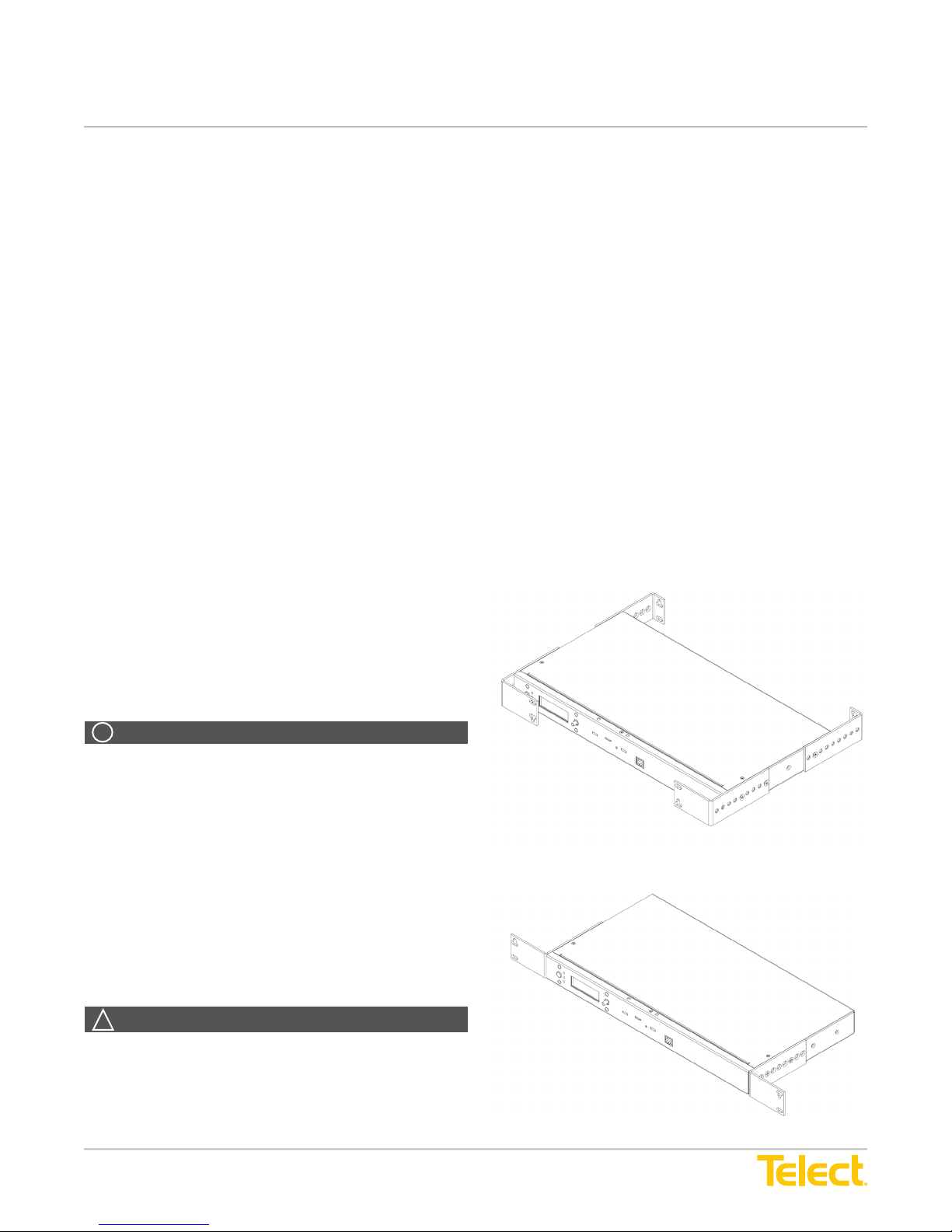
Figure 4 - Bracket Orientation as Shipped ............................................................................3
Figure 5 - Bracket Orientation for Rack Mounting ................................................................3
Tables
Specications ........................................................................................................................2
© Telect, Inc., All Rights Reserved, 145122-3 A0
1.509.926.6000 :: telect.com
ii
Page 3
nrgCONTROL-BT
Power :: nrgSMART™ Controller
1.1 Overview
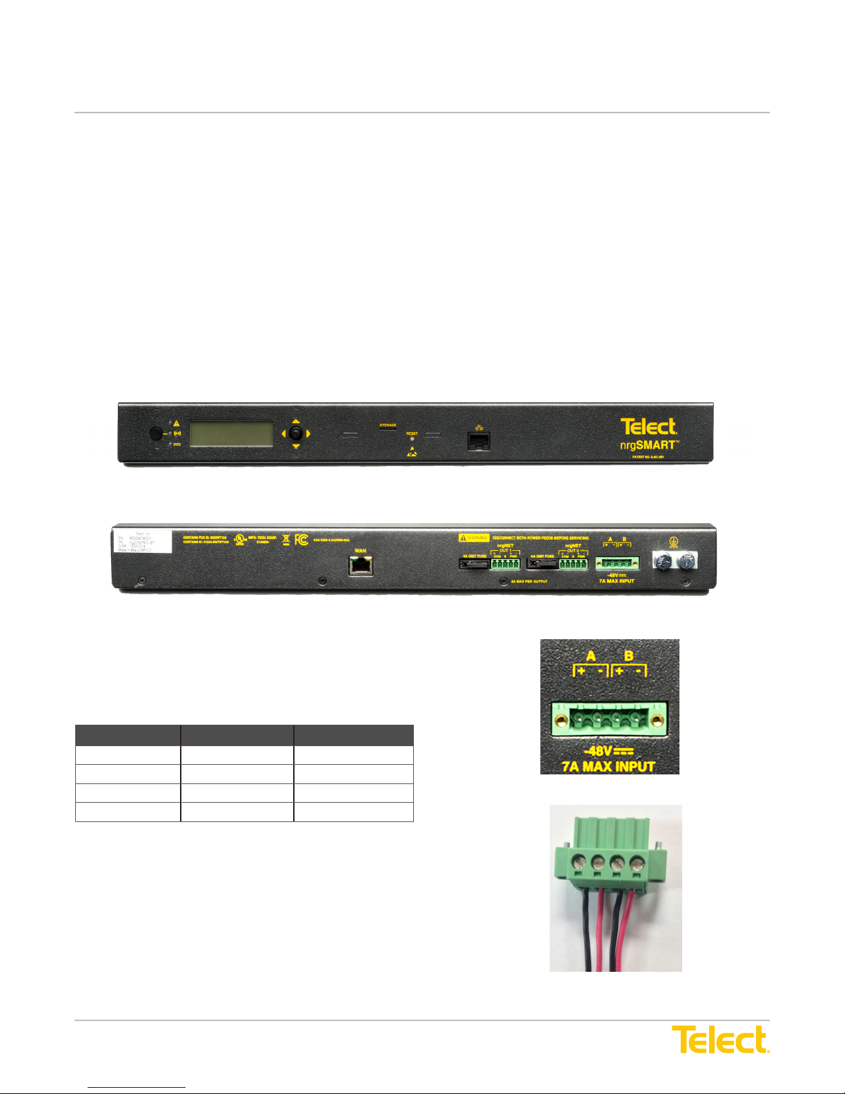
The Telect nrgCONTROL-BT coordinates and collects
data for up to 30 nrgSMART enabled devices. Panels are
connected over a simple daisy chain connection. One IP
address is all that is required for all attached PDU panels.
For new deployments the controller interface is built into the
nrgBDFB. For expansion, single rack deployment or outdoor
enclosures we provide the 1RU controller.
The nrgCONTROL-BT is capable of connecting to DC power
in the range of -20 to -57V. Redundant power input is also
congurable based on the pin-out description in Figure 3.
Figure 1 – nrgCONTROL-BT Front View
Using nrgSMART’s SNMP interface, pull data into your
network management system of choice to get network wide
access and visibility to sites that deploy the nrgSMART
controller/PDU panels. Get real-time data such as current,
voltage, breaker trips or blown fuses, and temperature for
individual circuits. Uniquely identify and label assets to their
individual circuit. It is now possible to track performance
based on asset.
Figure 2 – nrgCONTROL-BT Rear View
Pin Number Feed Voltage Polarity
Pin 1 A feed Positive voltage
Pin 2 A feed Negative voltage
Pin 3 B feed Positive voltage
Pin 4 B feed Negative voltage
Pin 1
Pin 2
Pin 3
Pin 4
Figure 3 – nrgCONTROL-BT DC power pin out
© Telect, Inc., All Rights Reserved, 145122-3 A0
1.509.926.6000 :: telect.com
1
Page 4
nrgCONTROL-BT
Power :: nrgSMART™ Controller
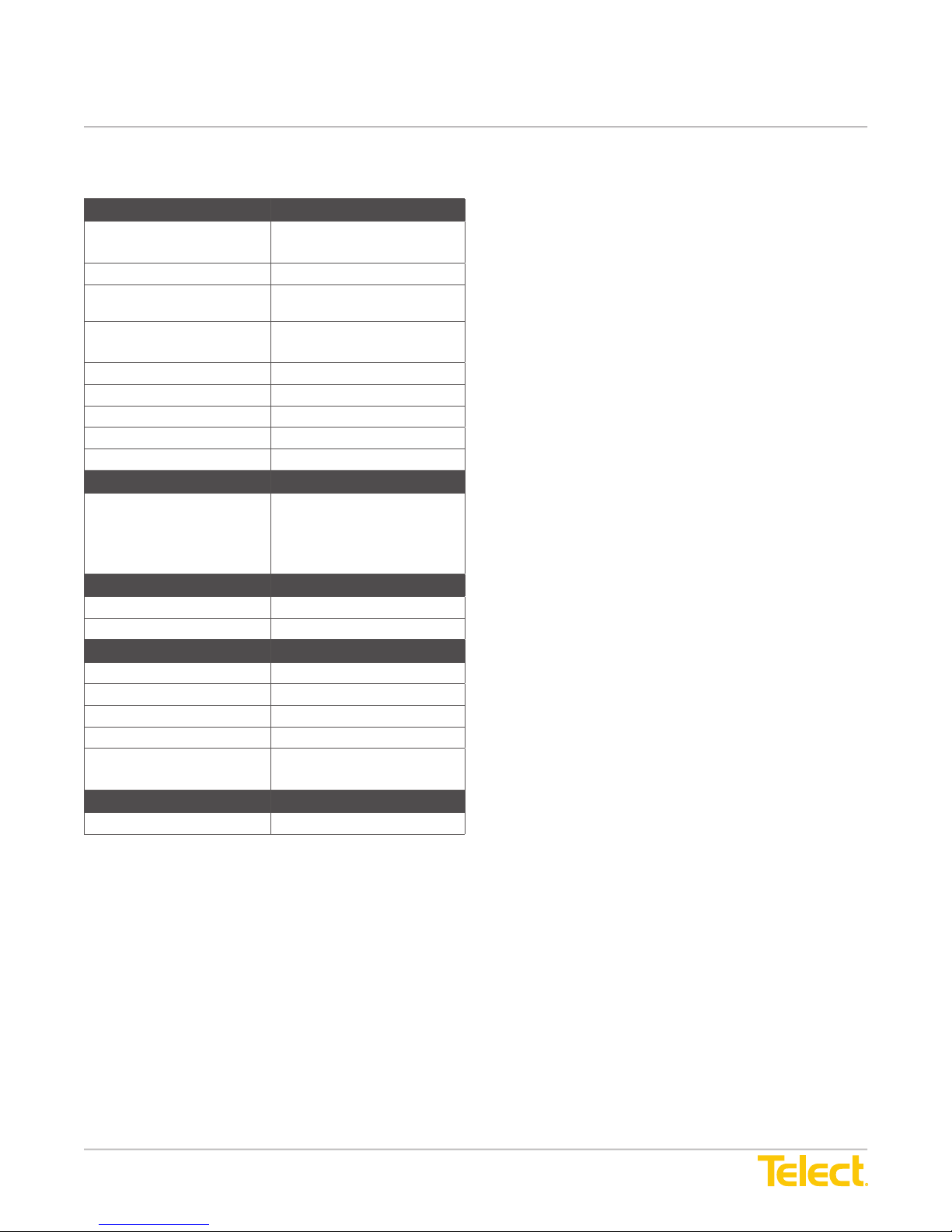
1.2 Specications Important Installation Guidelines
Inputs/Outputs Specication
Connection to
conguration wizard
Connection to data server 10/100 Ethernet, RJ-45 jack
Connection to
nrgSMART panels
Supported browsers Chrome (recommended)
Voltage range (nominal) -20V to -57V (nominal -48 VDC)
Input power wire size #18-12 AWG
Max. operating current 7A
SD card capacity 4 Gigabytes
SD card type Micro SD
10/100 Ethernet, RJ-45 jack
nrgNET
Firefox
Grounding Specication
Earth GND terminal bolts
(with washers) for dual-hole
compression lug
Two pair of 1/4-20 threaded
holes on 5/8-in. centers. Torque
bolts (using 7/16-in. or 12 mm
wrench) to 50-in./lb. (5.5 N•m),
max.
Environmental Specication
Temperature -5° to 55°C (23° to 131°F)
Humidity 0 to 90%, non-condensing
Mechanical Specication
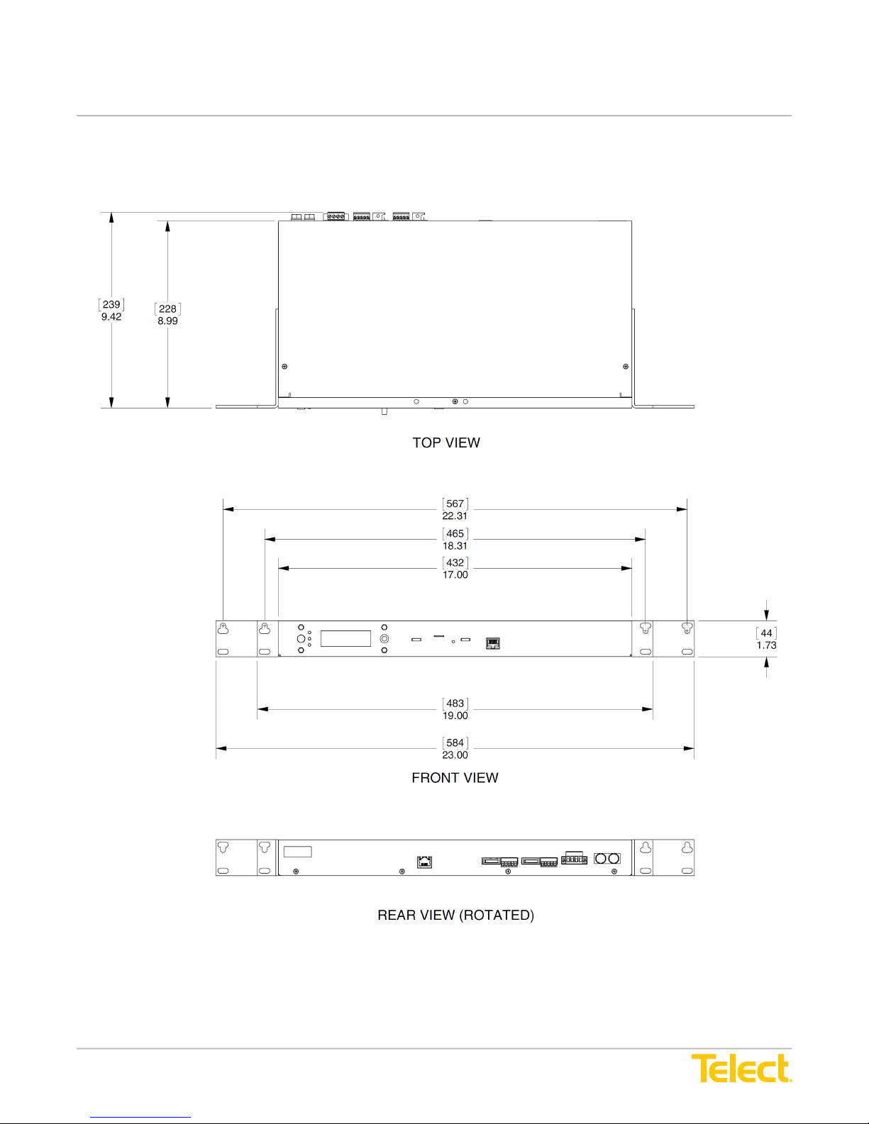
Dimension 17" W x 1.73" H x 8.99" D
Weight 8.7 lbs (10.7 lbs shipping)
Material Cold-rolled steel
Finish Gray, powder coat
Mounting 19" or 23" rack mounting; EIA
and WECO
Compliance
UL, NEBS level 3
• Elevated Operating Ambient - If you install this product
in a closed or multi-unit rack assembly, the
operating ambient temperature of the rack environment
may be greater than room ambient. Therefore,
consider installing the equipment in an environment
compatible with the maximum ambient temperature.
• Reduced Air Flow - When you install this equipment in
a rack, make sure you do not compromise the amount of
air ow required for safe operation of the equipment.
• Mechanical Loading - When you mount the equipment
in the rack, make sure to keep the mechanical load
balanced to prevent a hazardous condition.
• Circuit Overloading - Pay attention to the connection
of the equipment to the supply circuit and the effect that
overloading of the circuits might have on overcurrent
protection and supply wiring. Appropriately consider
equipment nameplate ratings when addressing
this concern.
• Reliable Earthing - Maintain reliable earthing of rackmounted equipment. Pay particular attention to supply
connections other than direct connections to the branch
circuit (e.g., use of power strips).
• Disconnect Device - Incorporate a readily available
disconnect device into the building installation wiring.
© Telect, Inc., All Rights Reserved, 145122-3 A0
1.509.926.6000 :: telect.com
2
Page 5
nrgCONTROL-BT
Power :: nrgSMART™ Controller
1.3 Installation
Inspection
Please read and understand all instructions before starting
installation. If you have questions, contact Telect Technical
Support at [email protected] or call 509.926.6000.
When you receive the equipment, carefully unpack it and
compare it to the packaging list. Please report any defective
or missing parts to Telect at [email protected] or call
509.926.6000.
Telect is not liable for transit damaged. If the product is
damaged, please report it to the carrier and contact Telect
Quality.
For service or warranty information, please visit the telect.
com website, or email inquiries to [email protected] and
click on the “Support” tab, or phone us at 509.926.6000.
NOTE: The nrgCONTROL-BT is suitable for installation
as part of both a Common Bonding Network (CBN) and
Isolated Bonding Network (IBN) for installation in Network
Telecommunications Facilities and OSP.
NOTE: Do not remove terminal protection brackets, until
panel is installed in a rack. If the panel is transported outside
of the shipping container, make sure the terminal protection
brackets are installed.
Rack Mounting
• The nrgCONTROL-BT panel can be mounted in 19-in. &
23-in. EIA and WECO racks.
• The nrgCONTROL-BT panel can be ush-mounted to
4-in extended in 1/2" increments.
1. Unscrew the mounting brackets from the panel and turn
them to the mounting position. See Figures 4 and
5 below.
2. Locate an unused rack position and mount panel to the
rack using the screws provided. It is best to mount the
panel as high as possible on the rack.
3. Tighten screws to 35 in.-lb (4.29 N•m). Telect recommends
using a seismic rack for best rigidity. Also, if you intend on
installing more than one panel per rack, you need to plan
a rack arrangement that dissipates heat efciently.
Figure 4 - Bracket Orientation as Shipped
!
ALERT
ALERT! Verify that all connections meet requirements
specied in local electric codes or operating company
guidelines before supplying power. Unit shall be protected by
a listed circuit breaker or branch-rated fuse rated maximum
10A.
INSTALL THIS PRODUCT WITHIN A RESTRICTED
ACCESS LOCATION WHERE ACCESS IS THROUGH THE
USE OF A TOOL, LOCK AND KEY, OR OTHER MEANS OF
SECURITY AND IS CONTROLLED BY THE AUTHORITY
RESPONSIBLE FOR THE LOCATION. ONLY QUALIFIED
TECHNICIANS MAY INSTALL AND MAINTAIN THIS
PRODUCT.
WARNING
!
WARNING! Failure to properly ground this equipment can
create hazardous conditions for installation personnel and for
the equipment.
© Telect, Inc., All Rights Reserved, 145122-3 A0
1.509.926.6000 :: telect.com
Figure 5 - Bracket Orientation for Rack Mounting
3
Page 6
nrgCONTROL-BT
Power :: nrgSMART™ Controller
1.4 nrgCONTROL nrgNET Connectivity
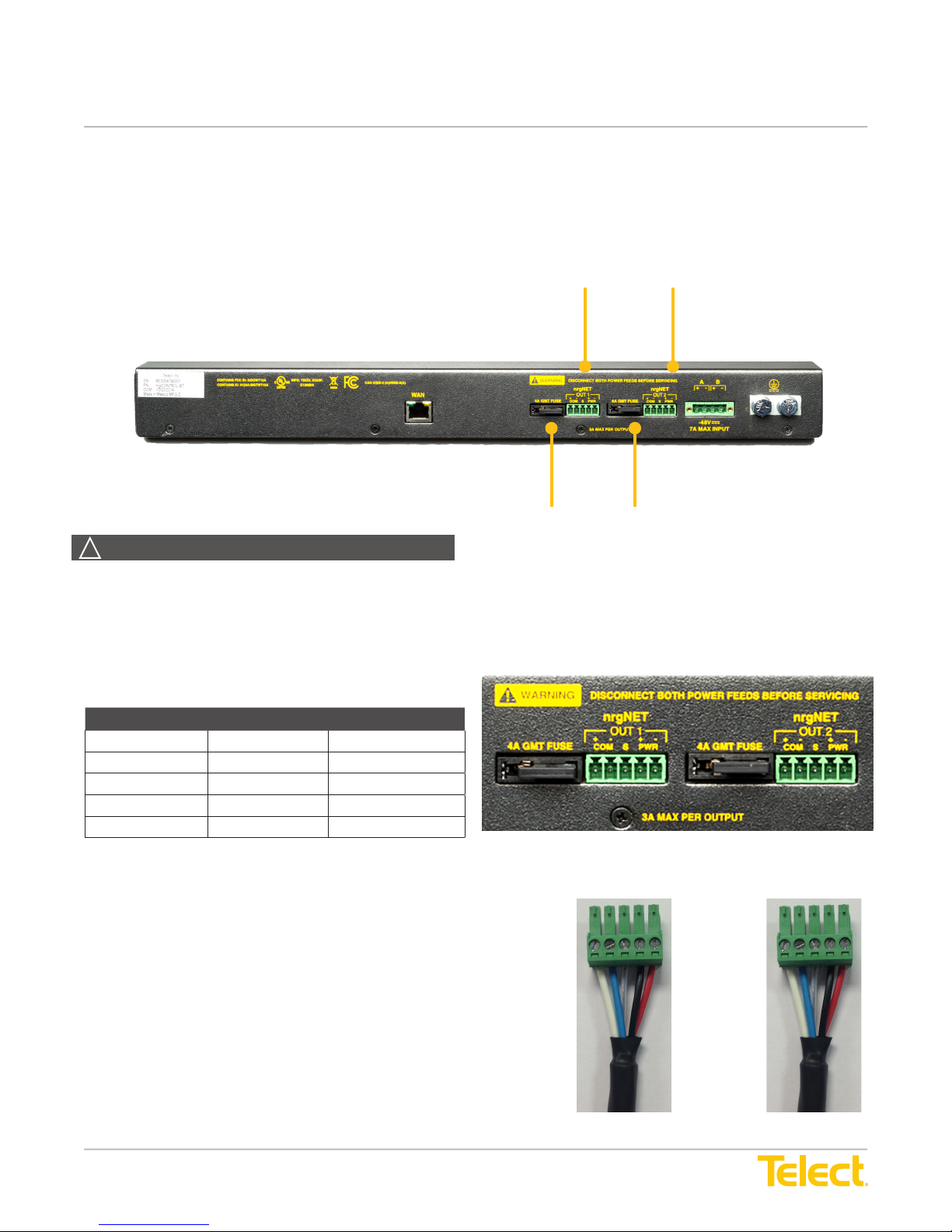
nrgNET is the Telect proprietary communication link between
nrgSMART panels and the nrgCONTROL controller. The
connection uses a single cable with four conductors to
provide power and data communication.
WARNING
!
nrgNET 1 and nrgNET 2 leg
outputs to nrgSMART panels
nrgNET 1 and nrgNET 2 leg power fuses
Standard GMT style (4A)
WARNING! Failure to disconnect power prior to connecting
nrgSMART PDUs will damage the nrgCONTROL-BT. Power
should be removed prior to connecting panels and servicing.
nrgNET Pin Outs
Pin Number Label Wire Color
Pin 1 COM + White
Pin 2 COM - Blue
Pin 3 SHLD Drain wire
Pin 4 PWR + Black
Pin 5 PWR - Red
Pin 1
Pin 2
Pin 3
Pin 4
Pin 5
Pin 1
Pin 2
Pin 3
Pin 4
Pin 5
© Telect, Inc., All Rights Reserved, 145122-3 A0
1.509.926.6000 :: telect.com
4
Page 7
nrgCONTROL-BT
Power :: nrgSMART™ Controller
1.5 nrgCONTROL Connectivity
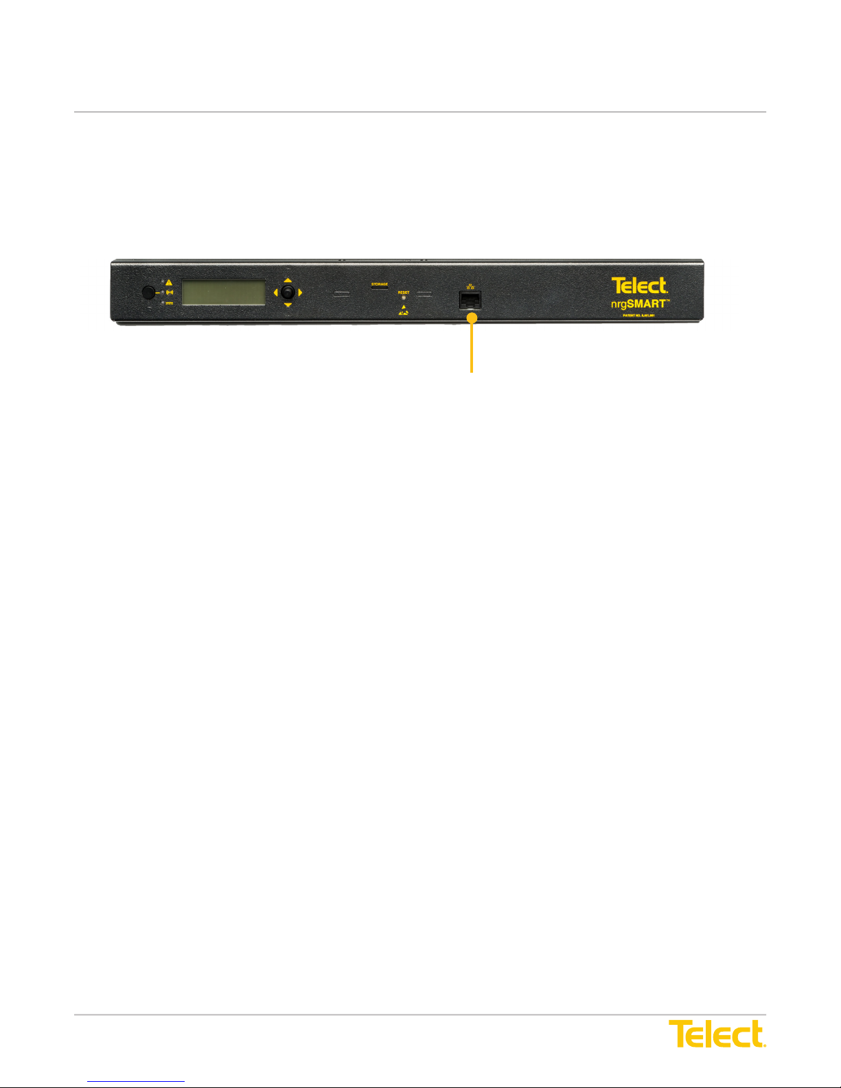
The nrgCONTROL panel utilizes the LAN port located on the
front of the unit to connect the controller to the data storage
location.
RJ-45 LAN port
The controller can be operated in the following modes simultaneously:
1. Local Only Mode
• The controller will collect data from all panel sensors that are connected to it over the nrgNET interface.
• No SNMP traps or data is sent for monitoring.
• The instantaneous sensor data can be viewed from the front of the controller’s LCD screen for all attached
monitoring panels.
2. SNMP Mode
• The LAN port must be connected and congured to operate on the same subnet as the customer dened SNMP/
NMS server address.
• The nrgSMART MIB table is available for download at the following URL: www.telect.com/NewProductDetail/
nrgsmart-controller
• SNMP traps can be set-up for current threshold crossings, breaker trips or blown fuses, voltage threshold
crossings and temperature threshold crossings.
• Sensor data and conguration data can be polled by issuing commands from the NMS.
• The NMS will have to manage and store all collected data.
The nrgCONTROL-BT uses a static IP address of 192.168.1.1 with a subnet mask of 255.255.255.0. You will need to
set up your PC or server to an address on the same subnet as the nrgCONTROL-BT. To do this, follow the steps below.
1. Connect a CAT5 cable to the front panel LAN connector of the nrgCONTROL-BT panel.
2. Go into Network Settings from either the Control Panel or the Network icon in the bottom right corner of the task bar
on your PC. Note: There will be different paths to get to these settings based on your operating system.
3. Double-click Ethernet or LAN connection.
4. Select Internet Protocol Version 4 (TCP/IPv4)
5. Change your setting from Obtain an IP Address Automatically to Use the Following IP Address in the subnet range of
192.168.1.2 - 192.168.1.254 subnet mask of 255.255.255.0; no gateway or DNS needed.
6. Hit OK on the next two screens to complete the change.
7. Open the nrgCONTROL-BT via a browser by its IP address of 192.168.1.1 Note: Chrome is the recommended
browser. Other supported browsers include Firefox.
8. The Conguration Wizard will be displayed.
For information on connecting and conguring your nrgSMART panels, please refer to nrgSMART Conguration Guide.
© Telect, Inc., All Rights Reserved, 145122-3 A0
1.509.926.6000 :: telect.com
5
Page 8
nrgCONTROL-BT
Power :: nrgSMART™ Controller
2.0 nrgCONTROL-BT Dimensions
Telect assumes no liability from the application or use of these products. Neither does Telect convey any license
under its patent rights or the patent rights of others. This document and the products described herein are subject
to change without notice.
© Telect, Inc., All Rights Reserved, 145122-3 A0
1.509.926.6000 :: telect.com
6
Page 9
nrgCONTROL-BT
Power :: nrgSMART™ Controller
FCC Class A Notice
This device complies with part 15 of the FCC Rules. Operation is subject to the following two conditions: (1)
This device many not cause harmful interference, and (2) this device must accept any interference received,
including interference that may cause undesired operation.
Note: This equipment has been tested and found to comply with the limits for a Class A digital device, pursuant to part 15
of the FCC Rules. These limits are designed to provide a reasonable protection against harmful interference when the
equipment is operated in a commercial environment. This equipment generates, uses and can radiate radio frequency
energy and, if not installed and used in accordance with the instruction manual, may cause harmful interference to radio
communications. Operation of this equipment in a residential area is likely to cause harmful interference in which case the
user will be required to correct the interference at his own expense.
Modication
Any modications made to this device that are not approved by Telect Inc. may void the authority granted to the user by the
FCC to operate this equipment.
ICES-003 Class A Notice - Avis NMB-003, Classe A
This Class A digital apparatus complies with Canadian ICES-003.
Cet appareil numérique de la classe A est conforme à la norme NMB-003 du Canada.
WARNING
!
WARNING! The intra-building port of the equipment is suitable for connection to intra-building or unexposed wiring
or cabling only. The intra-building port of the equipment MUST NOT be metallically connected to interfaces that
connect the OSP (Outside Plant) or its wiring. These interfaces are designed for use as intra-building interfaces only
(Type 2 or Type 4 ports as described in GR-1089) and require isolation from the exposed OSP cabling. The addition of
Primary Protectors is not sufcient protection in order to connect these interfaces metallically to OSP wiring.
ELECTROSTATIC DISCHARGE (ESD) PRECAUTIONS
ELECTROSTATIC DISCHARGE (ESD) PRECAUTIONS! When handling any electronic component or assembly you
must observe the following antistatic precautions to prevent damage. Always disconnect power from the server and
wear a grounded wrist strap when working around the nrgCONTROL-BT. Always wear a grounded wrist strap when
handling printed circuit boards. Treat all assemblies, components and interface connections as static-sensitive.
© Telect, Inc., All Rights Reserved, 145122-3 A0
1.509.926.6000 :: telect.com
7
 Loading...