

Page 1

LTX
Patch and Splice Panel
Installation Guide
Page 2

LTX Patch and Splice Panel
Installation Guide
Table of Contents
Chapter 1: Introduction ........................................................................................................................................... 4
1.1 Specications .................................................................................................................................................4
1.2 About this Guide .............................................................................................................................................5
1.3 Terminology .................................................................................................................................................... 5
1.4 LTX 4RU, 2RU and 1RU Panel Overview ......................................................................................................6
Chapter 2: Installation Considerations ..................................................................................................................9
2.1 Inspection .......................................................................................................................................................9
2.2 Unpacking.......................................................................................................................................................9
2.2.1 LTX 4RU, 2RU and 1RU Panel Contents ............................................................................................... 10
2.3 Installation Guidelines .................................................................................................................................. 11
2.4 Location and Space ...................................................................................................................................... 11
2.5 Tools and Equipment .................................................................................................................................... 11
Chapter 3: LTX Patch and Splice Panel Installation and Routing ..................................................................... 12
3.1 LTX Panel Component Installation ...............................................................................................................12
3.1.1 Entry/Exit Arc Installation ........................................................................................................................12
3.1.2 Routing Spool Installation ....................................................................................................................... 12
3.1.3 Splice Tray Installation............................................................................................................................13
3.1.4 Tray Platform Installation ........................................................................................................................15
3.1.5 Cable Clamp Bracket Installation ...........................................................................................................15
3.1.6 Cable Clamp Installation.........................................................................................................................17
3.1.7 Central Strength Member Holder Installation .........................................................................................18
3.1.8 Adapter Patch Plate Installation..............................................................................................................19
3.1.9 Panel Doors Installation..........................................................................................................................20
3.1.10 Designation Label Installation...............................................................................................................21
3.1.11 Installing Mounting Brackets on the LTX Panel ....................................................................................22
3.2 Install and Ground the LTX Panel on the Rack ............................................................................................23
Chapter 4: LTX Panel Cable and Fiber Installation and Routing .......................................................................24
4.1 Cable Installation and Routing......................................................................................................................24
4.1.1 IFC Cable Installation and Routing ......................................................................................................... 24
4.1.2 Install IFC in the Cable Clamp ................................................................................................................ 25
4.1.3 Route Protected 12 Strand Ribbon Fiber in LTX Panel Slack Storage Area ..........................................26
4.1.4 Install Ribbon Fibers in the Splice Tray ..................................................................................................27
4.1.5 Route Pigtail Fibers in the Splice Tray....................................................................................................28
4.2 Splice and Route Fibers ...............................................................................................................................31
4.3 Connect Fiber Jumpers to the Patch Panel .................................................................................................. 31
Chapter 5: Service ................................................................................................................................................. 34
5.1 Owner Maintenance .....................................................................................................................................34
5.1.1 High Insertion Loss and the Importance of Cleaning Connectors and Adapters ....................................34
5.2 Techincal Support ......................................................................................................................................... 35
5.3 In-Warranty Service ......................................................................................................................................35
5.4 Out-of-Warranty Service ...............................................................................................................................35
5.5 Repackage for Shipment .............................................................................................................................. 35
© Telect, Inc. All rights reserved. 148326 12.20.16 v2
1.509.926.6000 :: telect.com
2
Page 3

LTX Patch and Splice Panel
Installation Guide
List of Figures
Figure 1-1 LTX Patch and Splice Panel with SC Adapters ........................................................................................4
Figure 1-2 LTX 4RU Patch and Splice Panel Overview - Front and Rear Views ......................................................6
Figure 1-2-1 LTX 2RU Patch and Splice Panel Overview - Front and Rear Views ...................................................7
Figure 1-2-2 LTX 1RU Patch and Splice Panel Overview - Front and Rear Views ...................................................8
Figure 3-1 Entry/Exits Arcs Installation ....................................................................................................................12
Figure 3-2 Routing Spools Installation.....................................................................................................................12
Figure 3-3 4RU Splice Trays Installation .................................................................................................................13
Figure 3-3-1 2RU Splice Trays Installation ..............................................................................................................14
Figure 3-3-2 1RU Splice Trays Installation ..............................................................................................................14
Figure 3-4 4RU Tray Platform Installation ...............................................................................................................15
Figure 3-5 4RU Cable Clamp Bracket Installation ................................................................................................... 15
Figure 3-5-1 2RU Cable Clamp Bracket Installation................................................................................................16
Figure 3-5-2 1RU Cable Clamp Bracket Installation................................................................................................16
Figure 3-6 4RU Cable Clamp Installation ................................................................................................................ 17
Figure 3-6-1 2RU Cable Clamp Installation ............................................................................................................. 17
Figure 3-6-2 1RU Cable Clamp Installation ............................................................................................................. 17
Figure 3-7 4RU Central Strength Member Holder Installation ................................................................................. 18
Figure 3-8 4RU Adapter Patch Plate Installation .....................................................................................................19
Figure 3-8-1 2RU Adapter Patch Plate Installation ..................................................................................................19
Figure 3-8-2 1RU Adapter Patch Plate Installation ..................................................................................................19
Figure 3-9 4RU Door Installation ............................................................................................................................. 20
Figure 3-9-1 2RU Door Installation .......................................................................................................................... 20
Figure 3-10 4RU Designation Label Installation ...................................................................................................... 21
Figure 3-10-1 2RU Designation Label Installation ................................................................................................... 21
Figure 3-10-2 1RU Designation Label Installation ................................................................................................... 21
Figure 3-11 Installing Mounting Brackets on LTX 4RU Panels ................................................................................22
Figure 3-11-1 Installing Mounting Brackets on LTX 2RU Panels .............................................................................22
Figure 3-11-2 Installing Mounting Brackets on LTX 1RU Panels .............................................................................22
Figure 3-12 Install and Ground LTX Panel to the Rack ........................................................................................... 23
Figure 4-1 Securing IFC Cabling to the LTX 4RU Panel ......................................................................................... 25
Figure 4-1-1 Securing IFC Cabling to the LTX 2RU Panel ...................................................................................... 25
Figure 4-1-2 Securing IFC Cabling to the LTX 1RU Panel ...................................................................................... 25
Figure 4-2 Route Protected 12-Stranded Ribbon Fiber through LTX Panel Slack Storage Area ............................26
Figure 4-3 Installing Ribbon Fibers in the Splice Tray .............................................................................................27
Figure 4-4 Routing Pigtail Fibers in the 4RU Splice Tray ........................................................................................28
Figure 4-4-1 Routing Pigtail Fibers in the 2RU Splice Tray .....................................................................................29
Figure 4-4-2 Routing Pigtail Fibers in the 1RU Splice Tray .....................................................................................30
Figure 4-5 Connecting Fiber Jumpers to the 4RU Patch Panel ..............................................................................32
Figure 4-5-1 Connecting Fiber Jumpers to the 2RU Patch Panel ........................................................................... 33
Figure 4-5-2 Connecting Fiber Jumpers to the 1RU Patch Panel ........................................................................... 33
© Telect, Inc. All rights reserved. 148326 12.20.16 v2
1.509.926.6000 :: telect.com
3
Page 4
LTX Patch and Splice Panel
Installation Guide
Chapter 1: Introduction
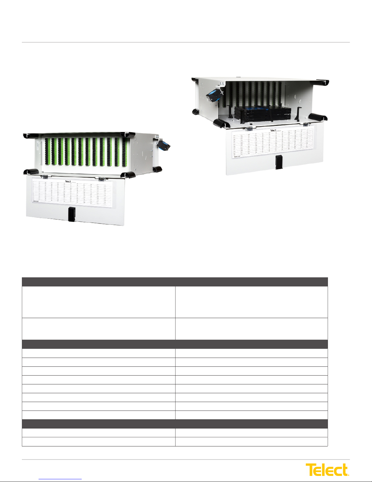
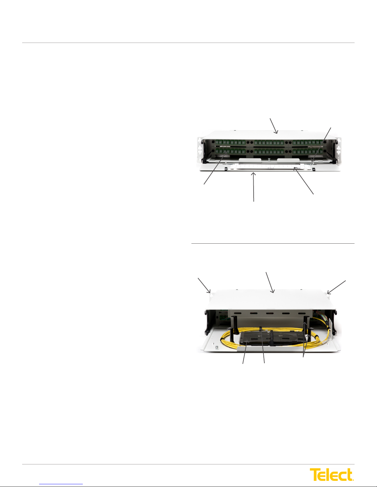
The Telect LTX Patch and Splice Panel consolidates
network ber splicing, patching and routing
requirements in a 4RU panel.
The LTX panel accommodates up to 288 fiber
terminations and houses eight splice trays.
144 Terminations Shown
Rear View
Front View
Figure 1-1 - LTX Patch and Splice Panel with SC Adapters
1.1 Specications
Dimensions and Weights
Dimensions 4RU: 7" H x 17" W x 17" D
2RU: 3.5" H x 17" W x 17" D
1RU: 1.75" H x 17" W x 17" D
Weight 4RU: 14.65 lbs.
2RU: 11.2 lbs.
1RU: 6.8 lbs.
Mechanical
Connector Type SC/UPC, SC/APC, LC/APC, LC/UPC, MPO/MTP
Access Front and Rear
Capacity Max. 288 port 4RU
Splicing Single Fusion / Mass Fusion / Stranded
Panel Mounting 19" or 23" with ETSI, EIA, or WECO spacing
Adapter Access Front/Rear Patch Panel
Material Aluminum/Steel
Compliance NEBS, ETSI, Zone 4 Seismic reliability
Environmental
Temperature Range -5°C to 55°C
Humidity 90%, non-condensing
© Telect, Inc. All rights reserved. 148326 12.20.16 v2
1.509.926.6000 :: telect.com
4
Page 5
LTX Patch and Splice Panel
Installation Guide
1.2 About this Guide
This manual provides a comprehensive overview and installation guidelines for the LTX Patch and Splice Panel. While
care has been taken to dene all necessary information, complete details may not be covered. If you have any questions,
contact Telect at [email protected] or call 1.509.926.6000.
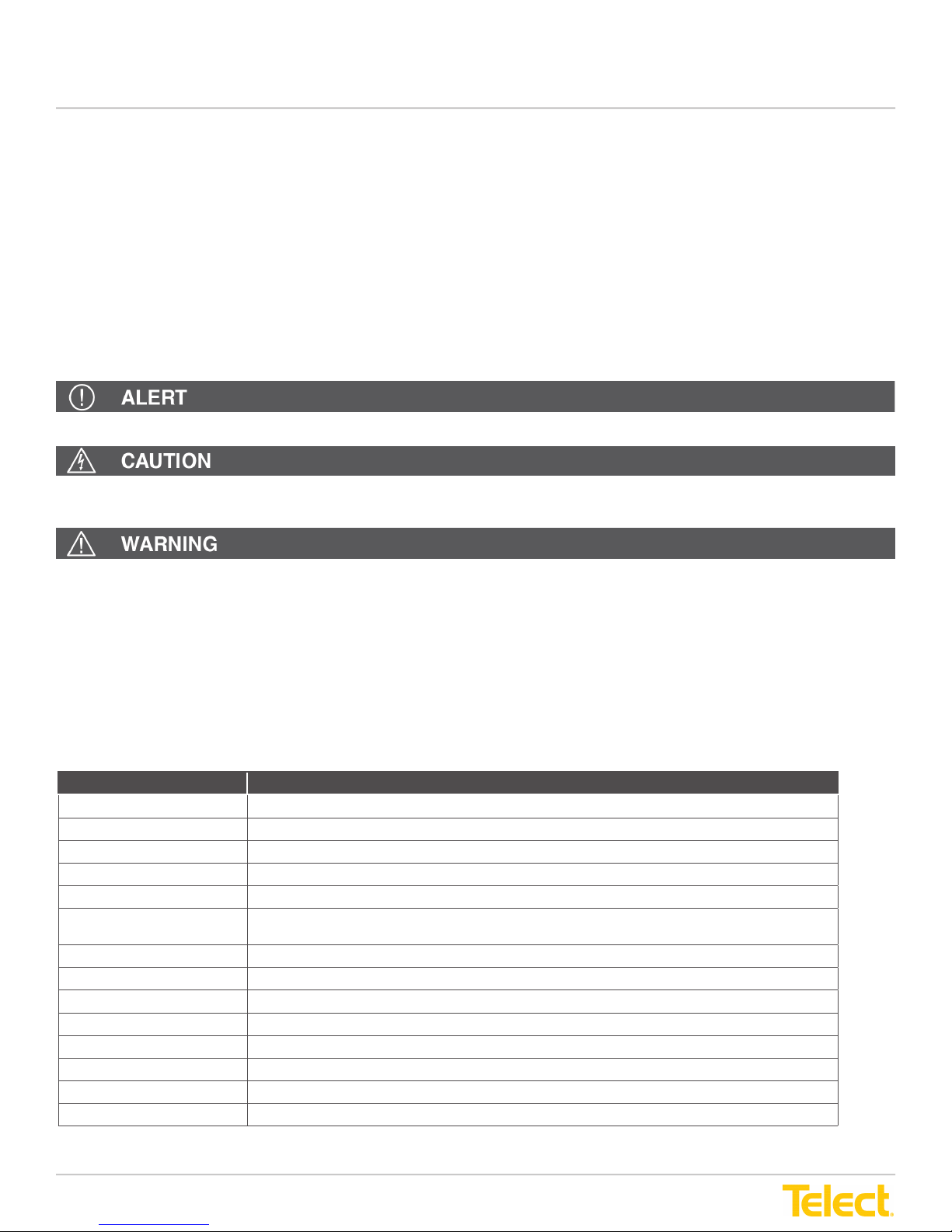
Throughout this guide, relevant and crucial information is displayed in the form of Notes, Alerts, Cautions and Warnings.
These notications are prominently displayed and their importance is indicated as follows:
NOTE: General information the user should pay special attention to.
Alert! Important information and/or instructions the user should adhere to.
CAUTION! Indicates a hazardous situation, which if not avoided could result in minor
or moderate injury.
WARNING: Indicates a potentially hazardous situation which if not avoided could result in death
or serious injury.
Telect assumes no liability from the application or use of these products. Neither does Telect convey any
license under its patent rights of others. This document and the products described herein are subject to change without
notice.
1.3 Terminology
The following list of acronyms and abbreviations are used throughout this manual.
Acronym/Abbreviation Term
IF IntraFacility Fiber
IFC IntraFacility Cable
LC Local Connector
MPO Multi-Fiber Push-On optical ber module interface type
NE Network Element
NEBS Network Equipment Building System (telecommunications product safety equipment rating
PC Physical Contact ber optic connector (single or multi-mode)
SC Standard Connector
TIA Telecommunications Industry Association
TIA/EIA-568 B.3 Telecommunication Standards for Commercial Cabling
TUV Technical Inspection Association (global product certication compliance marking)
UL Underwriter Laboratories (electrical standards)
APC Angled Physical Contact ber optic connector (single or multi-mode)
UPC Ultra Physical Contact ber optic connector (single or multi-mode)
standard)
© Telect, Inc. All rights reserved. 148326 12.20.16 v2
1.509.926.6000 :: telect.com
5
Page 6
LTX Patch and Splice Panel
Installation Guide
1.4 LTX Panel Overview
LTX 4RU
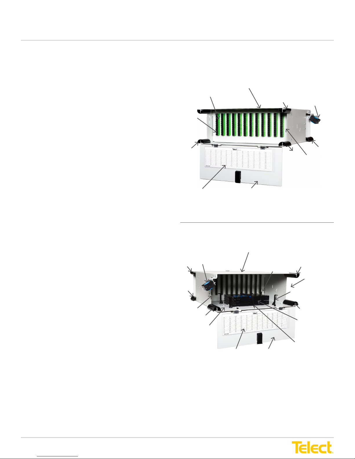
The Telect LTX patch and splice panel consolidates
network ber splicing, patching and routing requirements
in a 4RU panel.
The LTX 4RU panel accommodates:
• Up to 288 fiber terminations
• Stacked splice trays, housing 36 splice sleeve holders
per single fusion tray and 144 per mass fusion tray
• Single fusion/mass fusion options
• Velcro bands that secure trays inside the panel
• Routing spools to manage slack cable routing
• Panel mounted cable clamp for incoming cable
slack maintenance
• Convenient spring-hinged removable front and
rear doors
• Designation labels on front and rear doors
Interconnect and cross-connect cabling enter the LTX
panel at rear corner locations guided over rubber edge
protectors. Slack storage area in the rear of the panel
routes IntraFacility Cables (IFC) through the panel to
splice trays in the center of the panel. After splicing,
pigtail bers connect to patch plate mounted connectors
at the rear of the panel and ber jumpers connect to
patching adapters at the front.
LTX Patch and Splice Panel, Front View
(144 terminations shown)
Patch Plate with Adapters
Arc
Fiber
Jumper
Entry
Area
Arc
Designation
Card
(Front Side)
LTX Patch and Splice Panel, Rear View
(144 terminations shown)
Front Door
Arc
Cable Clamp
Arc
Jumper
Arc
Fiber
Entry
Area
LTX patch and splice panel patch plates
can accommodate:
• SC/UPC, SC/APC, LC/APC, LC/UPC are available in
patch plates with 6 or 8 terminations
• LC/SC available in patch plates with
12 terminations
• LC/UPC and LC/APC available in patch plates with
24 terminations
• MPO/MTP feed through patch plates available with 6
or 8 adapters
In addition, Telect offers a special factory-congured
integrated 4RU patch plate panel with up to 288
terminations (requires use of LC quad adapters).
Adapters are also offered in multi-mode versions. All
adapters include dust covers. All patch plates are
available in white or black.
Cable Clamp
Arc
Arc
Cable
Entry
Area
Arc
Slack
Storage
Area
Designation Label
(Rear Side)
Patch Plate with
Connectors
Velcro Tie
Rear Door
Arc
Cable
Entry Area
Routing Spool
Arc
Stacked Splice
Trays
Figure 1-2 - LTX 4RU Patch and Splice Panel Overview
- Front and Rear Views-
© Telect, Inc. All rights reserved. 148326 12.20.16 v2
1.509.926.6000 :: telect.com
6
Page 7
LTX Patch and Splice Panel
Installation Guide
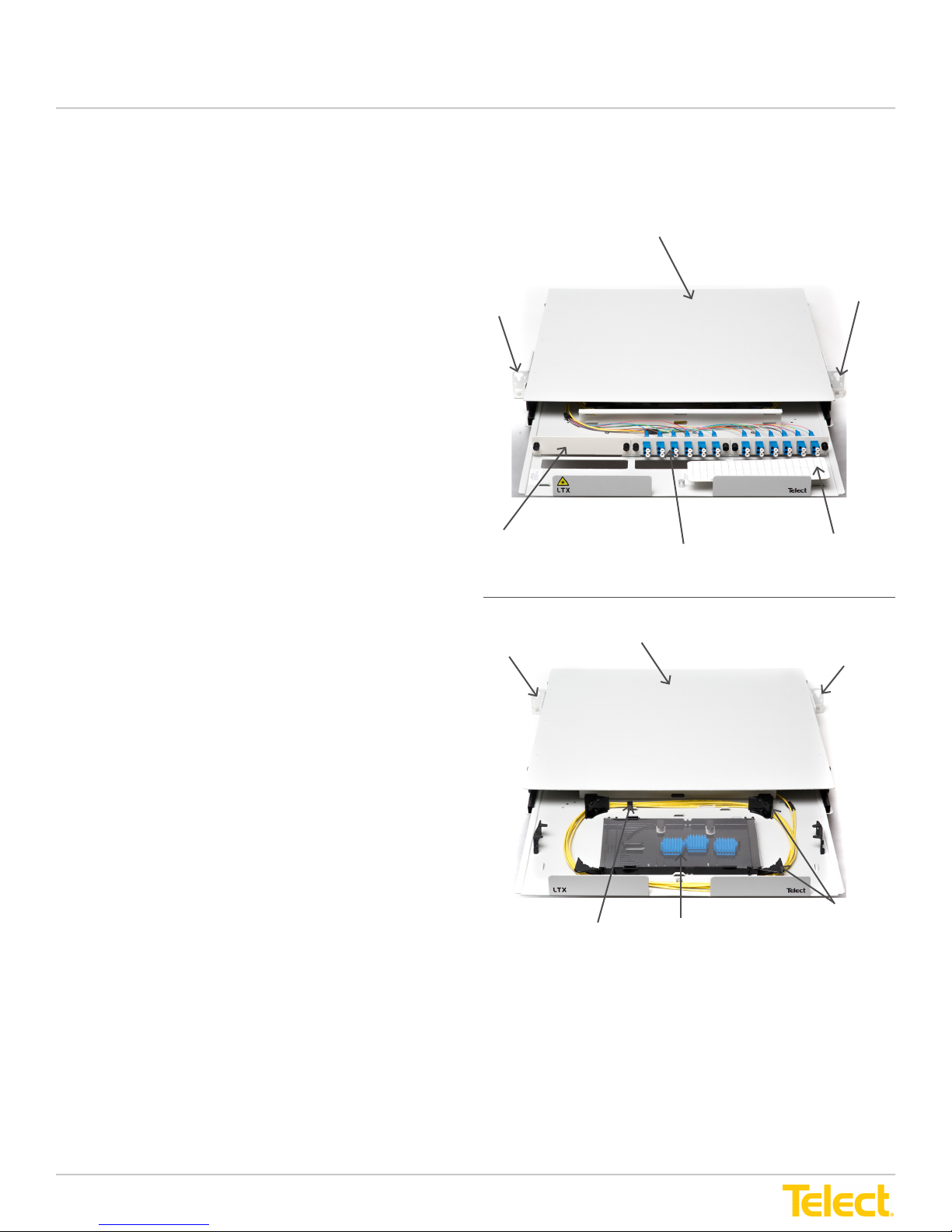
LTX 1RU
The Telect LTX patch and splice panel consolidates
network ber splicing, patching and routing requirements
in a 1RU panel.
The LTX 1RU panel accommodates:
• Up to 72 fiber terminations
• Stacked splice trays, housing 36 splice sleeve holders
per single fusion tray and 144 per mass fusion tray
• Single fusion/mass fusion options
• Velcro bands that secure trays inside the panel
• Routing spools to manage slack cable routing
• Panel mounted cable clamp for incoming cable
slack maintanence
• Designation label on the front
Interconnect and cross-connect cabling enter the LTX
panel at rear corner locations guided over rubber edge
protectors. Slack storage area in the rear of the panel
routes IntraFacility Cables (IFC) through the panel to
splice trays in the center of the panel. After splicing,
pigtail bers connect to patch plate mounted connectors
at the rear of the panel and ber jumpers connect to
patching adapters at the front.
LTX patch and splice panel patch plates
can accommodate:
Bracket
Patch Plate
LTX Patch and Splice Panel, Front View
Bracket
(24 terminations shown)
Patch Plate with Adapters
LTX Patch and Splice Panel, Rear View
(24 terminations shown)
Designation Label
Bracket
Bracket
• SC/UPC, SC/APC, LC/APC, LC/UPC are available in
patch plates with 6 or 8 terminations
• LC/SC available in patch plates with
12 terminations
• LC/UPC and LC/APC available in patch plates with
24 terminations
• MPO/MTP feed through patch plates available with 6
or 8 adapters
In addition, Telect offers a special factory-congured
integrated 1RU patch plate panel with up to 72
terminations (requires use of LC quad adapters).
Adapters are also offered in multi-mode versions. All
adapters include dust covers. All patch plates are
available in white or black.
Routing Spool
Velcro Tie
Splice Tray
Figure 1-2-1 - LTX 1RU Patch and Splice Panel Overview
- Front and Rear Views-
© Telect, Inc. All rights reserved. 148326 12.20.16 v2
1.509.926.6000 :: telect.com
7
Page 8
LTX Patch and Splice Panel
Installation Guide
LTX 2RU
The Telect LTX patch and splice panel consolidates
network ber splicing, patching and routing requirements
in a 2RU panel.
The LTX 2RU panel accommodates:
• Up to 144 fiber terminations
• Stacked splice trays, housing 36 splice sleeve holders
per single fusion tray and 144 per mass fusion tray
• Single fusion/mass fusion options
• Velcro bands that secure trays inside the panel
• Routing spools to manage slack cable routing
• Panel mounted cable clamp for incoming cable
slack maintanence
• Convenient spring-hinged removable front and
rear doors
• Designation labels on front and rear doors
Patch Plate with Adapters
LTX Patch and Splice Panel, Front View
(48 terminations shown)
Door Hinge
Designation Label
Front Door
Interconnect and cross-connect cabling enter the LTX
panel at rear corner locations guided over rubber edge
protectors. Slack storage area in the rear of the panel
routes IntraFacility Cables (IFC) through the panel to
splice trays in the center of the panel. After splicing,
pigtail bers connect to patch plate mounted connectors
at the rear of the panel and ber jumpers connect to
patching adapters at the front.
LTX patch and splice panel patch plates
can accommodate:
• SC/UPC, SC/APC, LC/APC, LC/UPC are available in
patch plates with 6 or 8 terminations
• LC/SC available in patch plates with
12 terminations
• LC/UPC and LC/APC available in patch plates with
24 terminations
• MPO/MTP feed through patch plates available with 6
or 8 adapters
In addition, Telect offers a special factory-congured
integrated 2RU patch plate panel with up to 144
terminations (requires use of LC quad adapters).
Adapters are also offered in multi-mode versions. All
adapters include dust covers. All patch plates are
available in white or black.
LTX Patch and Splice Panel, Rear View
Bracket
Splice Tray
(48 terminations shown)
Velcro Tie
Bracket
Routing
Spool
Figure 1-2-2 - LTX 2RU Patch and Splice Panel Overview
- Front and Rear Views-
© Telect, Inc. All rights reserved. 148326 12.20.16 v2
1.509.926.6000 :: telect.com
8
Page 9
LTX Patch and Splice Panel
Installation Guide
Chapter 2: Installation Considerations
WARNING: Verify all connections meet requirements specied in local electric codes or operating company
guidelines before supplying power. Unit must be protected by a listed circuit breaker or branch-rated fuse
sufcient to interrupt power levels.
WARNING: Use of fully insulated tools is required when working with any AC or DC circuits.
WARNING: Fiber cables transmit invisible infrared light. To avoid eye damage or blindness, never look directly
into bers or connectors.
CAUTION! These instructions presume you have veried that the Telect equipment being installed is compatible
with the rest of the system including power, ground, circuit protection, signal characteristics, equipment from
other vendors and local codes or ordinances.
ALERT! This product must be installed and maintained only by qualied technicians.
ALERT! Install this system according to company requirements. It is recommended to install the
system in a Restricted Access Location (RAL) where access is limited through use of tool (i.e., lock and key) or
other means of security and be controlled by the authority responsible for the location.
ALERT! Prior to panel installation, ensure there is enough space in front and rear to access cabling.
ALERT! Only use components and crimping tools approved by agencies or certifying bodies recognized in your
country or region, such as Underwriter’s Laboratories (UL), TUV, etc.
ALERT! Do not stand on ber or ber cables.
2.1 Inspection
When you receive the equipment, carefully unpack it and compare it to the packaging list. Please report any defective
or missing parts to Telect at [email protected] or call 1.509.926.6000. Keep all documentation that comes with
your shipment.
Please read and understand all instructions before starting installation. If you have any questions, contact Telect at
[email protected] or call 1.509.926.6000.
The panel is wrapped with a high-strength plastic. Exercise care when unpacking and setting the equipment
in place.
Telect is not liable for transit damage. If the product is damaged, please report it to the carrier and
contact Telect at 1.509.926.6000 or through email at [email protected].
2.2 Unpacking
The LTX 4RU patch and splice panel is 7" H x 17" W x 17" D and weighs 14.65 lbs.
The LTX 2RU patch and splice panel is 3.5" H x 17" W x 17" D and weighs 11.2 lbs.
The LTX 1RU patch and splice panel is 1.75" H x 17" W x 17" D and weighs 6.8 lbs.
These panels come pre-assembled as one unit.
Upon receipt of your order, carefully unpack it and compare it with the packing list and the order placed. While items
described below are a comprehensive list that includes the LTX panel, splice trays with splice sleeves, spools, brackets,
and doors, the contents of your order may vary.
© Telect, Inc. All rights reserved. 148326 12.20.16 v2
1.509.926.6000 :: telect.com
9
Page 10

LTX Patch and Splice Panel
Installation Guide
2.2.1 LTX Panel Contents
4 RU
• LTX patch and splice panel
• Tray platform
• Splice trays
• Splice sleeve holders
• Arcs (edge protectors)
• Velcro bands
• Routing spools
2 RU
• LTX patch and splice panel
• Splice trays
• Splice sleeve holders
• Arcs (edge protectors)
• Velcro bands
• Routing spools
• Removable doors (spring-hinged
swing down)
• Designation labels (front and rear)
• Cable clamp bracket
• Cable clamp with bushing sleeves
• Mounting brackets (to mount to 19" or
23" rack)
• Installation guide
• Removable doors (spring-hinged
swing down)
• Designation labels (front and rear)
• Cable clamp bracket
• Cable clamp with bushing sleeves
• Mounting brackets (to mount to 19" or
23" rack)
• Installation guide
1 RU
• LTX patch and splice panel
• Splice trays
• Splice sleeve holders
• Arcs (edge protectors)
• Velcro bands
• Routing spools
© Telect, Inc. All rights reserved. 148326 12.20.16 v2
1.509.926.6000 :: telect.com
• Designation labels (front)
• Cable clamp bracket
• Cable clamp with bushing sleeves
• Mounting brackets (to mount to 19" or
23" rack)
• Installation guide
10
Page 11

LTX Patch and Splice Panel
Installation Guide
2.3 Installation Guidelines
Elevated Operating Ambient Temperature - If installed in a closed or multi-unit rack assembly, the operating ambient
temperature of the rack environment may be greater than room ambient. Therefore, consideration should be given to
installing the equipment in an environment compatible with the maximum ambient temperature (Tma) specified by
the manufacturer.
Mechanical Loading - Mounting of the equipment in the rack should be such that a hazardous condition is not achieved
due to uneven mechanical loading.
2.4 Location and Space
The LTX patch and splice panel requires space in the front and rear for access to patching, splicing and cabling. Leave as
much side clearance for tray and panel removal and worker access as required by your application or local regulations.
Plan the input/output, upward/downward (cable feed) layout of each panel and its position in the rack before beginning
LTX panel installation.
LTX panels adapt to standard 19" or 23" ETSI racks with EIA, ETSI and WECO spacing and nominal 3¼" extensions
beyond the front rack ange.
2.5 Tools and Equipment
No special tools required.
© Telect, Inc. All rights reserved. 148326 12.20.16 v2
1.509.926.6000 :: telect.com
11
Page 12
LTX Patch and Splice Panel
Installation Guide
Chapter 3: LTX Patch and Splice Panel Installation and Routing
3.1 LTX Panel Component Installation
If not already installed, install LTX panel components prior to installing cabling and bers, or mounting the
panel to a rack.
LTX panel components include entry/exit arcs, splice tray platform with routing spools, velcro banding, stacked splice
trays, one or two cable clamp brackets with cable clamps, front and rear doors, designation cards for front and rear of the
panel and an adapter patch plate panel with connectors and adapters.
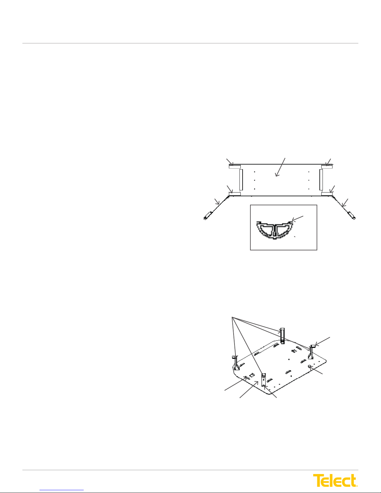
3.1.1 Entry/Exit Arc Installation
Refer to
The installation instructions apply to the LTX 4RU only
At the front of the LTX panel, four entry/exit split arcs protect
top and bottom corners where ber jumpers enter the panel.
At the rear of the panel, entry/exit split arcs protect top and
bottom corners where IntraFacility Cables (IFC) enter the LTX
panel. Arcs can be removed if needed to accommodate other
LTX panel attachments.
At each corner of the LTX panel:
1. Position the center groove of the entry/exit arc in front of the
2. Slide the entry/exit arc onto the corner entryway.
Figure 3-1
for this procedure.
metal edge on the LTX panel.
NOTE: The arcs install in the rear of the panel.
3.1.2 Routing Spool Installation
Refer to
The installation instructions apply to the LTX 4RU, 2RU
& 1RU
Figure 3-2
for this procedure.
LTX Patch and Splice Panel
Arc
Arc
Side View
Arc
Front View
Center
Groove
Figure 3-1 - Entry/Exit Arc Installation
Routing Spools
Arc
Arc
DoorDoor
Routing Spool
Overhang
Follow these instruction incase spools are not already installed
by the manufacturer. Routing spools are installed on the tray
platform before the platform is installed in the LTX panel.
Routing spools protect centrally located splice trays and
route IFC in the rear of the LTX panel through the slack
storage area.
1. On the tray platform, locate the four routing spool
screw holes.
2. Position routing spools on the tray platform so that screw
holes align. For correct alignment, the routing spool
overhang should face toward the outside of the platform.
3. Insert a screw from the bottom of the tray platform up
and into the screw hole of each routing spool and
hand tighten.
4. Adjust routing spool positions to best accommodate cable
routing and tighten screws using a Phillips screwdriver.
© Telect, Inc. All rights reserved. 148326 12.20.16 v2
1.509.926.6000 :: telect.com
12
Tie-Down
Slot
Tray Platform
Platform
Thumb Screw
Routing Spool Screw
Attaches through bottom of
tray platform
Figure 3-2 - Routing Spool Installation
Page 13
LTX Patch and Splice Panel
Installation Guide
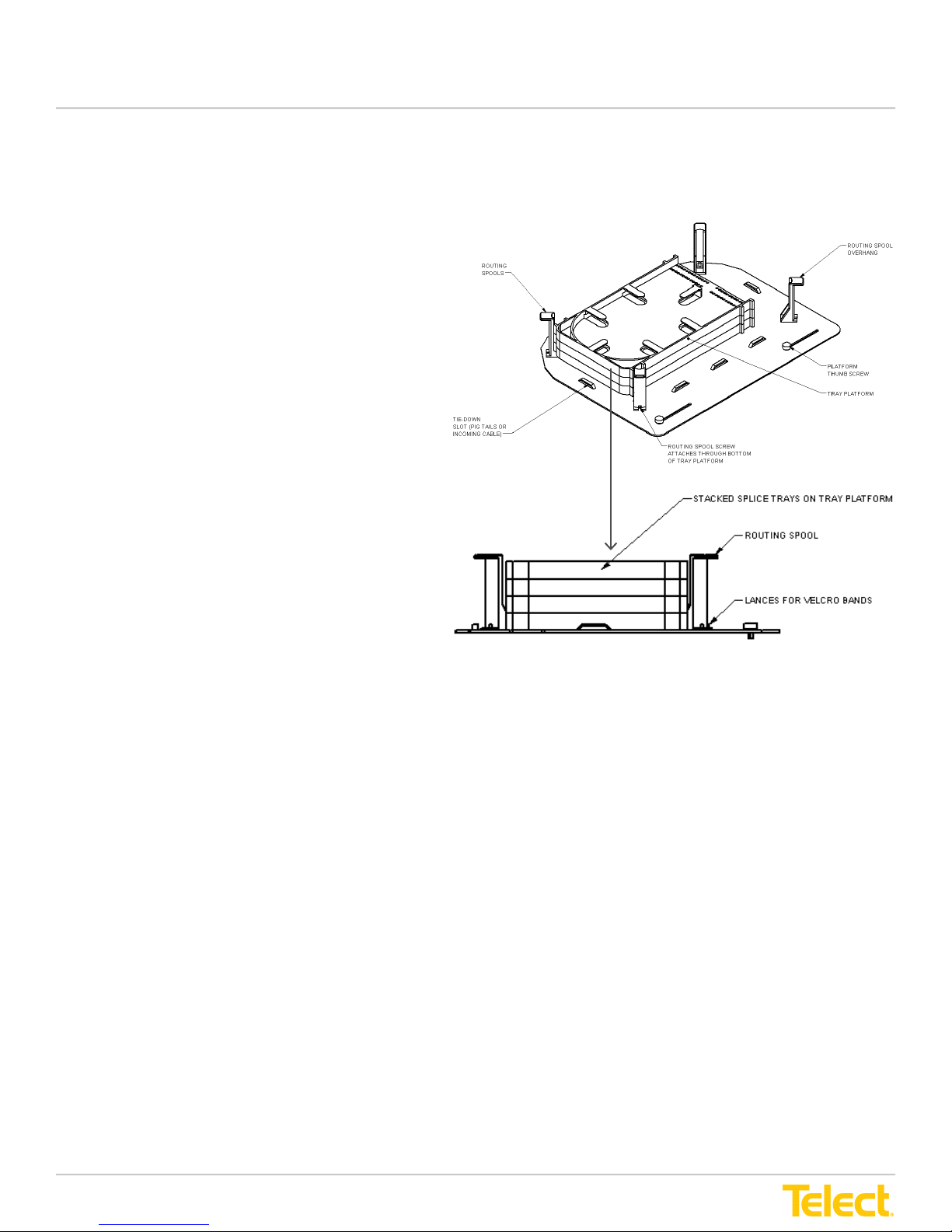
3.1.3 Splice Tray Installation
The installation instructions apply to the LTX 4RU
Refer to
Splice trays stack together on the tray platform. Trays
sit in the center platform surrounded by routing spools.
Trays hook together and are secured on the panel with
velcro bands.
1. Attach a velcro zip-tie band at the front and rear
2. Place the rst splice tray in the center of the platform
3. Place the next tray on top of the rst tray. Each side
4. Repeat Step 3 for the remaining trays.
5. Pull each velcro band up and over the stacked splice
Figure 3-3
center tie-down slot on the tray platform.
To do this:
a. Slide the band through the tie-down slot
and into the zip-tie opening at the end of
the velcro band.
b. Tighten the band to the slot.
c. Repeat the process at the opposite side,
attaching the velcro band to the platform's
tie-down slot.
(long side of the tray toward the front of the tray
platform) between routing spools, tie-down slots and
metal tabs. There will be a small amount of space
between the metal tabs and tray.
of the tray has two tabs that snap into slots securing
it to the tray below. Snap trays together.
trays and attach them together to secure the trays to
the platform.
for this procedure.
Figure 3-3 4RU Splice Tray Installation
* The number of splice trays will depend on the
number of connectors.
© Telect, Inc. All rights reserved. 148326 12.20.16 v2
1.509.926.6000 :: telect.com
13
Page 14
LTX Patch and Splice Panel
Installation Guide
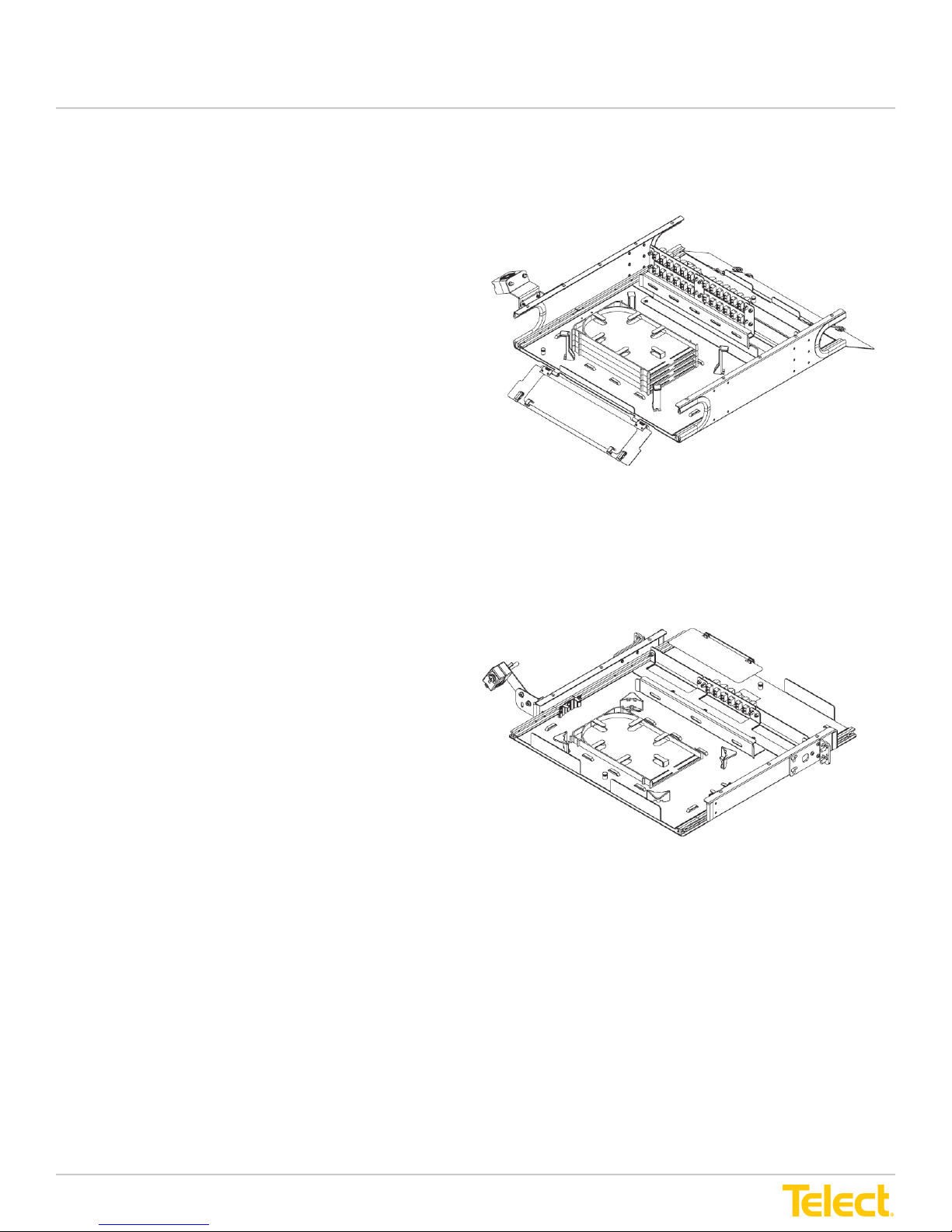
The installation instructions apply to the 2RU & 1RU
Refer to
Splice trays stack together on the tray platform. Trays
sit in the center platform surrounded by routing spools.
Trays hook together and are secured on the panel with
velcro bands.
1. Attach a velcro zip-tie band at the front and rear
2. Place the rst splice tray in the center of the platform
3. Place the next tray on top of the rst tray. Each side
4. Repeat Step 3 for the remaining trays.
5. Pull each velcro band up and over the stacked splice
Figure 3-3-
center tie-down slot on the tray platform.
To do this:
a. Slide the band through the tie-down slot
and into the zip-tie opening at the end of
the velcro band.
b. Tighten the band to the slot.
c. Repeat the process at the opposite side,
attaching the velcro band to the platform's
tie-down slot.
(long side of the tray toward the front of the tray
platform) between routing spools, tie-down slots and
metal tabs. There will be a small amount of space
between the metal tabs and tray.
of the tray has two tabs that snap into slots securing
it to the tray below. Snap trays together.
trays and attach them together to secure the trays to
the platform.
1 & 3-3-2 for this procedure.
Figure 3-3-1 2RU Splice Tray Installation
*The number of splice trays will depend on the
number of connectors.
© Telect, Inc. All rights reserved. 148326 12.20.16 v2
1.509.926.6000 :: telect.com
Figure 3-3-2 1RU Splice Tray Installation
14
Page 15
LTX Patch and Splice Panel
Installation Guide
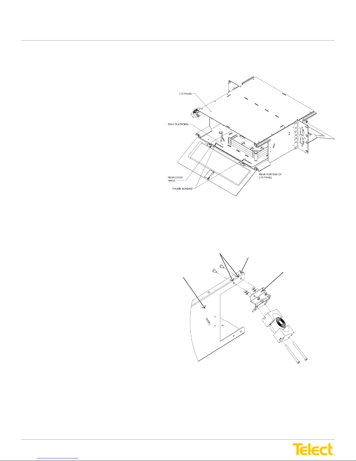
3.1.4 Tray Platform Installation
The installation instructions apply to the LTX 4RU
Refer to
Figure 3-4
for this procedure.
The tray platform sits in the bottom center of the rear
portion of the LTX panel. The platform contains routing
spools, tray banding, tie-down slots and splice trays.
The tray platform can be rotated out from inside the
LTX panel or can be removed for splicing.
1. Position the tray platform on the bottom of the LTX
panel in the rear portion of the tray. Center the
platform tray between the sidewalls. Screw holes
for the tray are near rear door hinges.
2. Align the two thumb screw holes in the platform
tray with the screw holes in the bottom of
the panel.
NOTE: It is recommended that routing spools,
splice tray bands and empty splice trays are
pre-installed before the tray platform is installed
in the panel.
3. Insert thumb screws through the top of the tray
platform into the screw holes in the panel bottom.
4. Rotate screws to tighten. Loosening one of the
screws allows the tray platform to rotate out from
inside the panel when needed.
3.1.5 Cable Clamp Bracket Installation
The installation instructions apply to the LTX 4RU
Refer to
Figure 3-5
for this procedure.
LTX Panel
Figure 3-4 4RU Tray Platform Installation
Two
Screws
Upper Rear
Corner
Cable
Clamp
Bracket
Incoming cables route from above or below and enter the
LTX panel at one of the upper rear corners. The cable
clamp bracket is used to house the cable clamp which
secures the cable to the panel.
1. Position cable clamp bracket with the straight side
up and the angled side facing down on the outside
upper corner edge at the rear of the LTX Panel.
2. Align the two screw holes in the top portion of the
bracket with the screw holes at the top edge of the
rear overhang on the LTX panel.
3. Insert two Phillips screws through the bracket from
the outside into the panel edge screw holes
and tighten.
© Telect, Inc. All rights reserved. 148326 12.20.16 v2
1.509.926.6000 :: telect.com
Figure 3-5 4RU Cable Clamp Bracket Installation
15
Page 16
LTX Patch and Splice Panel
Installation Guide
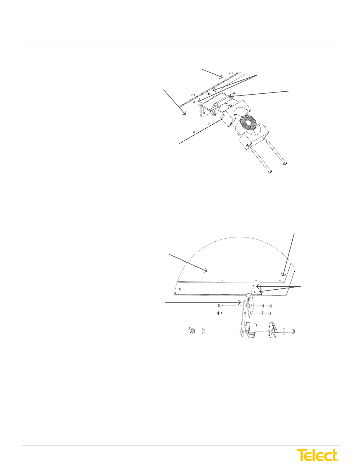
The installation instructions apply to the
LTX 2RU & 1RU
Refer to
Figure 3-5-1 & Figure 3-5-2
for
this procedure.
Incoming cables route from above or
below and enter the LTX panel at one
of the upper rear corners. The cable
clamp bracket is used to house the
cable clamp which secures the cable to
the panel.
1. Position cable clamp bracket with
the straight side up and the angled
side facing down on the outside
upper corner edge at the rear of the
LTX Panel.
2. Align the two screw holes in the
top portion of the bracket with the
screw holes at the top edge of the
rear overhang on the LTX panel.
3. Insert two Phillips screws through
the bracket from the outside into
the panel edge screw holes
and tighten.
* Leave sufcient IFC slack to allow
drawer to open properly.
Upper Rear
Corner
LTX Panel
Screws
Figure 3-5-1 2RU Cable Clamp Bracket Installation
Cable
Clamp
Bracket
Upper Rear
Corner
LTX Panel
Cable Clamp
Bracket
Screws
Figure 3-5-2 1RU Cable Clamp Bracket Installation
© Telect, Inc. All rights reserved. 148326 12.20.16 v2
1.509.926.6000 :: telect.com
16
Page 17
LTX Patch and Splice Panel
Installation Guide
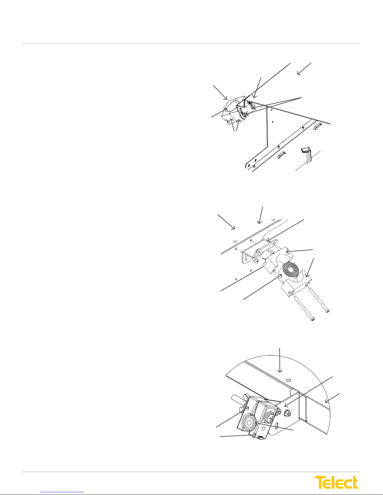
3.1.6 Cable Clamp Installation
The installation instructions apply to the LTX 4RU
Refer to
Figure 3-6
for this procedure.
The cable clamp, consists of rubber clamp halves that contain
bushing leaves in the center. To snugly t around the cable,
bushing leaves can be removed from the center of the clamp
to accommodate various sizes of incoming cable. The rubber
circle should be removed from the outer rubber square before
starting installation.
Additionally, the clamp can be repositioned after mounting at
the LTX panel if needed.
1. Determine diameter of the incoming cable.
2. Measure the inside of the cable clamp and remove
enough bushing leaves so that the rubber cable clamp
halves and remaining bushing leaves will t snugly
around the cable.
3. Position cable clamp so that screw holes align in both
clamp halves and the cable clamp bracket.
4. Insert the two clamp screws to secure the clamp on
the cable clamp bracket. The bracket allows for some
adjustment of the clamp as needed.
5. Insert nuts to secure the screws in the bracket while
tightening the screws in the cable clamps. The clamp is
mounted at a slight angle when attached to the bracket.
Cable Clamp
Clamp
Bushing
Leaves
LTX Panel
LTX Panel
Rear Corner
Cable Clamp
(Attaches to bracket
with adjustable
screws)
Clamp
Halves
Figure 3-6 4RU Cable Clamp Installation
Rear Corner
Cable Clamp
(Attaches to bracket
with adjustable
screws)
Clamp
Halves
The installation instructions apply to the LTX 2RU & 1RU
Refer to Figure 3-6-1 & 3-6-2 for this procedure.
The cable clamp, consists of rubber clamp halves that contain
bushing leaves in the center. To snugly t around the cable,
bushing leaves can be removed from the center of the clamp
to accommodate various sizes of incoming cable. The rubber
circle should be removed from the outer rubber square before
starting installation.
Additionally, the clamp can be repositioned after mounting at
the LTX panel if needed.
1. Determine diameter of the incoming cable.
2. Measure the inside of the cable clamp and remove
enough bushing leaves so that the rubber cable clamp
halves and remaining bushing leaves will t snugly
around the cable.
3. Position cable clamp so that screw holes align in both
clamp halves and the cable clamp bracket.
4. Insert the two clamp screws to secure the clamp on
the cable clamp bracket. The bracket allows for some
adjustment of the clamp as needed.
5. Insert nuts to secure the screws in the bracket while
tightening the screws in the cable clamps. The clamp is
mounted at a slight angle when attached to the bracket.
Clamp
Bushing
Leaves
Figure 3-6-1 2RU Cable Clamp Installation
LTX Panel
Clamp
Halves
Clamp
Bushing
Leaves
Figure 3-6-2 1RU Cable Clamp Installation
Cable Clamp
(Attaches to bracket
with adjustable
screws)
Rear Corner
© Telect, Inc. All rights reserved. 148326 12.20.16 v2
1.509.926.6000 :: telect.com
17
Page 18

LTX Patch and Splice Panel
Installation Guide
3.1.7 Central Strength Member Holder Installation
The installation instructions apply to the LTX 4RU
Refer to
Figure 3-7
for this procedure.
The LTX patch and splice panel central strength
member holder is installed on the same side of the
rear panel sidewall as the cable clamp.
1. Determine position for central strength member
holder below the cable clamp and along the
sidewall of the LTX panel.
2. Align central strength member holder screw hole
with the screw hole in the LTX panel.
3. Insert screw into the holder and through the
sidewall from the inside of the LTX panel.
4. Position holder at desired position and tighten
screw with a Phillips screwdriver.
Cable Clamp Bracket
LTX Panel
Cable Clamp
Rear Sidewall
Figure 3-7 4RU Central Strength Member Holder Installation
Central
Strength
Member
Screw
© Telect, Inc. All rights reserved. 148326 12.20.16 v2
1.509.926.6000 :: telect.com
18
Page 19
LTX Patch and Splice Panel
Installation Guide
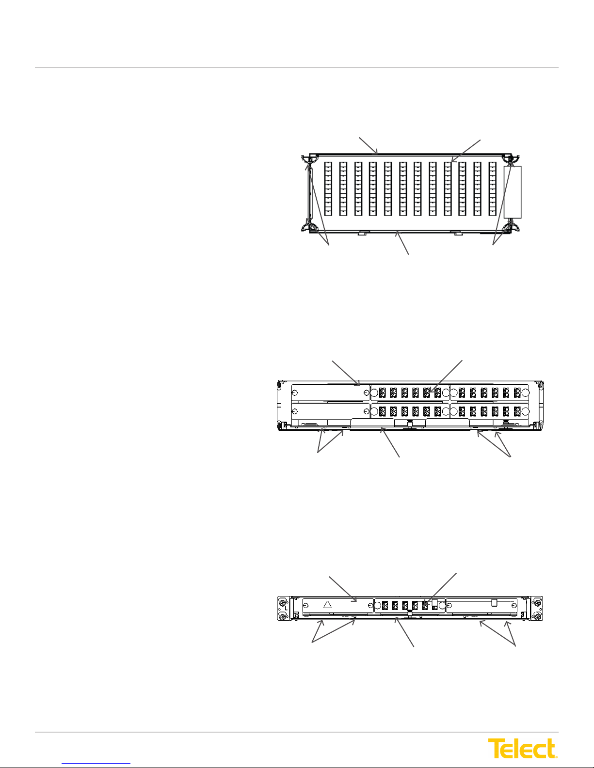
3.1.8 Adapter Patch Plate Installation
The installation instructions apply to the LTX 4RU, 2RU
& 1RU
Refer to
Figure 3-8, Figure 3-8-1 & 3-8-2
for this procedure.
The adapter patch plate installs at the front of the LTX
patch and splice panel. The patch plate comes with
adapters pre-installed. Pigtail bers from the splice tray
will connect to connectors at the rear and ber jumpers
will connect to adapters at the front of the patch plate.
1. Position the patch plate at the front of the LTX
patch and splice panel with ber jumper adapters
facing toward the front of the LTX panel and pigtail
connectors facing the rear of the LTX panel.
2. On one side of the LTX panel, align top and bottom
screw holes with patch plate screw holes. (4RU)
3. From the outside of the LTX panel, insert screws and
hand tighten.
4. On the other side of the LTX panel, align top and
bottom screw holes with patch plate screw holes.
5. From the outside of the LTX panel, insert screws and
hand tighten.
6. Ensure patch plate is centered and there is a little
clearance around the plate and the panel.
7. Use a Phillips screwdriver to tighten all four
screws.
LTX 4RU Panel
Front View
Screws
Some clearance between Patch
Plate and LTX Panel
Adapter Patch Plate
(144 SC Terminations shown)
Screws
Figure 3-8 4RU Adapter Patch Plate Installation
LTX 2RU Panel
Front View
Adapter Patch Plate
(48 Terminations Shown)
* Patch plates on the 2RU & 1RU are attached to
the tray, not on the chassis like the 4RU.
Screws
Some clearance between Patch
Plate and LTX Panel
Figure 3-8-1 2RU Adapter Patch Plate Installation
LTX 1RU Panel
Front View
Screws
Some clearance between Patch
Adapter Patch Plate
(48 Terminations Shown)
Plate and LTX Panel
Figure 3-8-2 1RU Adapter Patch Plate Installation
Screws
Screws
© Telect, Inc. All rights reserved. 148326 12.20.16 v2
1.509.926.6000 :: telect.com
19
Page 20
LTX Patch and Splice Panel
Installation Guide
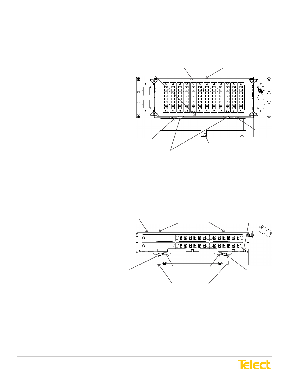
3.1.9 Panel Door Installation
The installation instructions apply to the LTX 4RU
& 2RU
Refer to
Figure 3-9, Figure 3-9-1 for this procedure.
Spring-hinged doors mount to the front and rear
bottom edges of the LTX panel.
1. On the LTX panel locate the two round mounting
pin holders along the front bottom edge.
2. Position the door at along the edge of the
panel bottom.
3. Press the door edge toward the panel bottom
edge while sliding the hinge pins out toward
the sides.
4. Slowly release the two hinge pins into the
mounting pin holders on the bottom edge of
the LTX panel so that they are inserted into
the slots.
5. Pull the door up to the closed position to ensure
that spring hinges operate correctly.
6. Repeat Steps 1-5 to install the other door.
Latch doors in the closed position by pressing
down on the center door latch (4RU) or door
latch tabs (2RU) while pushing the door in.
Release the latch or door tabs so that the tab
catches in the slot at the top of the LTX panel.
To open, press down on the door latch or door
tabs to release the latch or tabs and swing the
door down.
Bottom
(of panel)
Door Hinge
Round Mounting Pin Holders
LTX 2RU Panel
LTX 4RU Panel
Door Latch Slot
(on top of panel)
Door Latch Tab
Door
Figure 3-9 4RU Door Installation
Door Latch Slots
(on top of panel)
Door
Hinge
Bottom
(of panel)
© Telect, Inc. All rights reserved. 148326 12.20.16 v2
1.509.926.6000 :: telect.com
Door Hinge
Round Mounting Pin
Holders
Door Latch Tabs
Door Hinge
Figure 3-9-1 2RU Door Installation
20
Page 21
LTX Patch and Splice Panel
Installation Guide
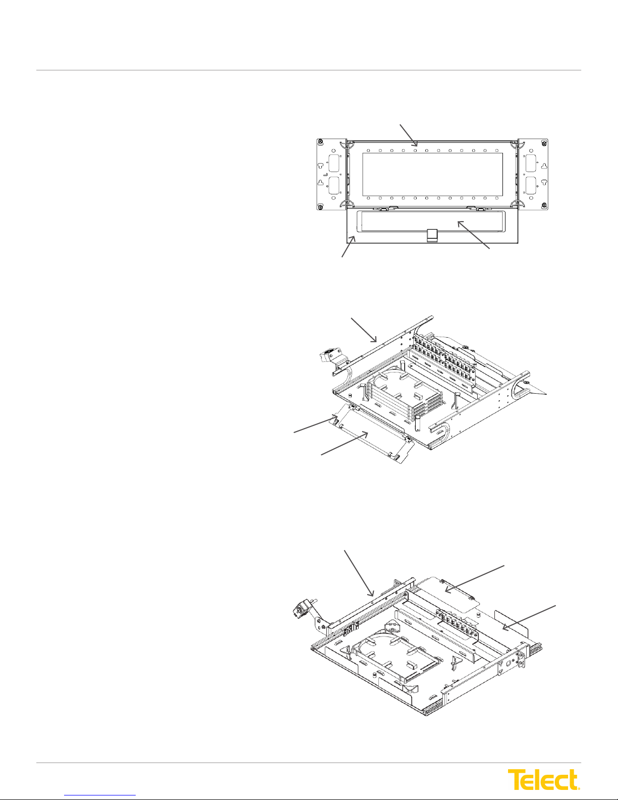
3.1.10 Designation Label Installation
The installation instructions apply to the LTX 4RU, 2RU
& 1RU
Refer to
for this procedure.
Designation labels are used to identify adapter ber
jumper information at the front of the panel and
connector pigtail ber information at the rear of
the panel.
1. Open the door to the front or rear of the LTX panel
2. Slide the designation label into the cover
Designation label for the front of the LTX panel
Designation label for the rear of the LTX panel
Figure 3-10, Figure 3-10-1 & Figure 3-10-2
all the way so that the clear cover on the inside of
the door is visible.
positioning it so that numbers can be read easily
with the door open.
(ber jumper adapter side) is marked "FRONT
SIDE" on the bottom corner.
(pigtail ber connector side) is marked "REAR
SIDE" on the bottom corner.
NOTE: After installing both designation labels,
ensure they are installed on the correct side of the
LTX panel.
Door
Figure 3-10 4RU Designation Label Installation
LTX 2RU Panel
LTX 4RUPanel
Clear Cover for
Designation Label
* Designation label for the 1RU is located on the
front tray platform.
Door
Clear Cover for
Designation Label
Figure 3-10-1 2RU Designation Label Installation
LTX 1RU Panel
Clear Cover for
Designation Label
Tray
© Telect, Inc. All rights reserved. 148326 12.20.16 v2
1.509.926.6000 :: telect.com
Figure 3-10-2 1RU Designation Label Installation
21
Page 22
LTX Patch and Splice Panel
Installation Guide
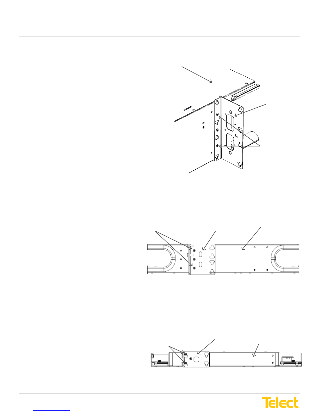
3.1.11 Installing Mounting Brackets on the LTX Panel
The installation instructions apply to the LTX 4RU, 2RU
& 1RU
Refer to
for this procedure.
The LTX panel mounting brackets are used to attach
the LTX panel to a 19" or 23" EIA, ETSI or WECO rack.
There are two rows of screw holes along the inside
walls of the LTX panel that can be used for mounting
brackets to the LTX panel.
1. Align mounting bracket screw holes with the screw
2. Insert screws through outside holes of the bracket
3. Using a Phillips screwdriver, tighten screws to
4. Repeat Steps 1 - 3 to mount bracket on adjacent
Figure 3-11, Figure 3-11-1 & Figure 3-11-2
holes in the sidewall of the LTX panel.
into the panel sidewall.
secure the bracket to the panel.
sidewall of the LTX panel.
LTX 4RU Panel
Mounting
Bracket
Screws
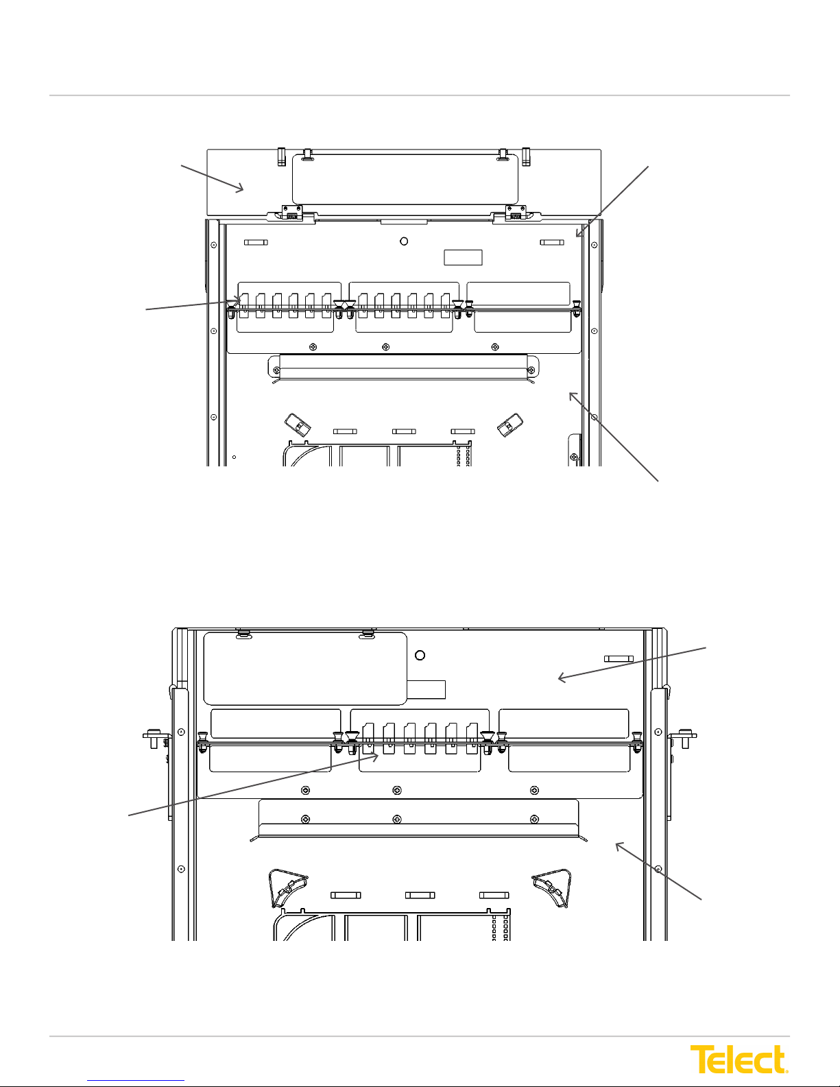
Figure 3-11 Installing Mounting Brackets on LTX 4RU Panels
Mounting
Screws
Figure 3-11-1 Installing Mounting Brackets on LTX 2RU Panels
Mounting Bracket
Screws
Bracket
LTX 2RU Panel
LTX 1RU Panel
© Telect, Inc. All rights reserved. 148326 12.20.16 v2
1.509.926.6000 :: telect.com
Figure 3-11-2 Installing Mounting Brackets on LTX 1RU Panels
22
Page 23
LTX Patch and Splice Panel
Installation Guide
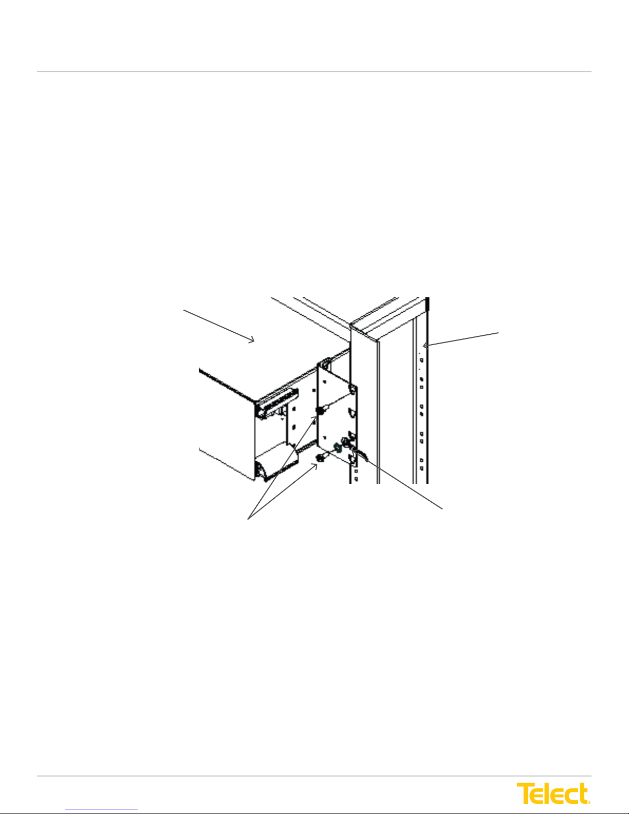
3.2 Install and Ground the LTX Panel to the Rack
Refer to
LTX patch and splice panels adapt to standard 19" and 23" standard EIA, ETSI or WECO racks.
1. Position LTX Panel mounting bracket between rack panels aligning screw holes so that panel is in
2. Insert four, 12-24 thread forming screws supplied (two on each side), to secure the panel to the rack.
3. If needed, include a ground lug and star washer (one ground lug with #14 AWG stranded wire per chassis.)
4. Tighten screws using a Phillips screwdriver.
Figure 3-12
desired position.
for this procedure.
LTX Panel
Rack
Insert Screws
Figure 3-12 Install and Ground LTX Panel to the Rack
© Telect, Inc. All rights reserved. 148326 12.20.16 v2
1.509.926.6000 :: telect.com
Insert Ground Lug
and Star Washer
with stranded wire
23
Page 24

LTX Patch and Splice Panel
Installation Guide
Chapter 4: LTX Panel Cable and Fiber Installation and Routing
WARNING! To avoid eye damage or blindness, never look directly into bers or connectors.
CAUTION! Do not connect bers to the adapters before all pigtail bers have been installed and spliced
at the splice tray.
CAUTION! Wear safety glasses while working with exposed ber optic ber. Do not touch eyes while
working with ber optic bers.
LTX patch and splice panels can be used to either interconnect or cross-connect Network Elements (NE). The panels are
typically used to interconnect IF (IntraFacility) splices from the LTX panel to network elements, to interconnect one system
of network elements to another, as in a demarcation, or to cross-connect network elements within the same system.
Fiber installation involves splicing, patching and storage using LTX patch and splice panels. Splicing begins with
installation of the IntraFacility Cable (IFC) at the rear of the LTX Panel. Each IFC ribbon ber contains 12 optic bers.
Each LTX splice tray handles up to 36 splices (three IFC ber ribbons).
The IFC routes to the LTX panel from above or below and is clamped at the side of the LTX panel with a cable clamp that
holds it in position. Protected ribbon bers then route around splice trays in the slack storage area of the LTX panel. Extra
ribbon should be measured out and routed through the panel to provide for splicing requirements.
In the rear of the LTX panel and at the front of the splice trays, cables are clamped and unprotected ber ribbons are
measured out and routed through the splice tray to splice sleeve holders.
At the rear of the LTX panel, pigtail ber strands route from connectors that attach to adapters with ber jumpers at the
front of the LTX panel. The pigtail bers route into the splice tray at the corner opposite to where the incoming IFC ribbon
bers route into the tray.
The loose ribbon and pigtail ber strands are then spliced (interconnected) with resulting splices placed into splice sleeve
holders in the center of the splice tray.
4.1 Cable Installation and Routing
4.1.1 IFC Cable Installation and Routing
The IntraFacility Cable (IFC) is brought in from above or below the LTX patch and splice panel.
The IFC is clamped to the cable clamp mounted on the top rear corner of the LTX panel. Protected 12-strand ber ribbons
route from the cable into the LTX panel through the slack storage area. Routing spools protect splice trays from routed
cables. Cables can be secured in the panel with velcro bands that attach to tie down slots on the tray platform and along
the sides and top of the LTX panel.
At the splice tray, 12-strand ribbon bers are broken out of the protected cabling and route through the tray for splicing.
© Telect, Inc. All rights reserved. 148326 12.20.16 v2
1.509.926.6000 :: telect.com
24
Page 25
LTX Patch and Splice Panel
Installation Guide
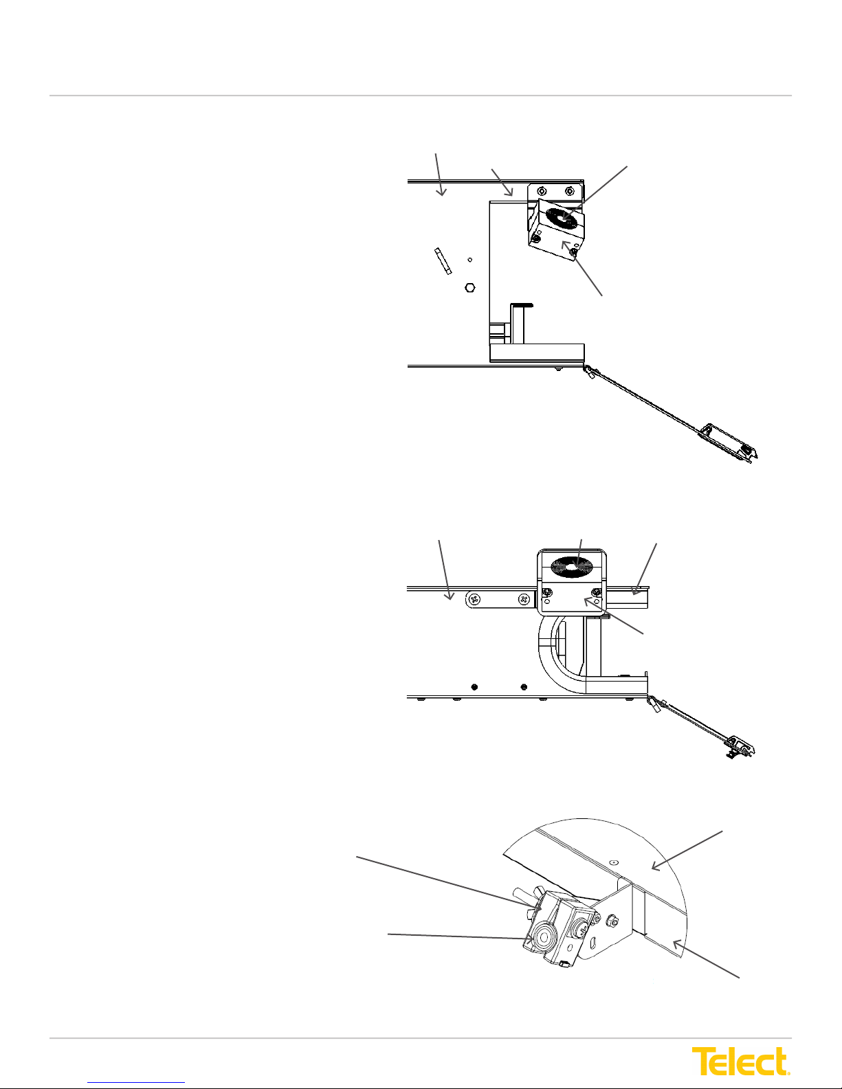
4.1.2 Installing IFC in the Cable Clamp
The installation instructions apply to the LTX 4RU
Refer to
Cable clamp halves contain removable center layers to
accommodate various sizes of cable.
1. Measure the diameter of the incoming IFC.
2. If needed, remove and discard leaves from
3. Clamp remaining bushing halves of the cable
The installation instructions apply to the
LTX 2RU & 1RU
Figure 4-1
the center of the cable clamp until the correct
dimension (the diameter of the IFC) is obtained.
clamp around the IFC. The two rubber bushings t
the IFC riser/plenum cable.
for this procedure.
LTX 4RU Panel
Rear Corner
Figure 4-1 Securing IFC Cabling to the LTX 4RU Panel
IFC Installs into
LTX 2RU Panel
center of clamp
IFC Installs into
Center of Clamp
Cable Clamp
Rear Corner
Refer to
for this procedure.
Cable clamp halves contain removable center layers to
accommodate various sizes of cable.
1. Measure the diameter of the incoming IFC.
2. If needed, remove and discard leaves from
3. Clamp remaining bushing halves of the cable
Figure 4-1-1 & Figure 4-1-2
the center of the cable clamp until the correct
dimension (the diameter of the IFC) is obtained.
clamp around the IFC. The two rubber bushings t
the IFC riser/plenum cable.
Cable Clamp
IFC Installs into
center of clamp
Cable Clamp
Figure 4-1-1 Securing IFC Cabling to the LTX 2RU Panel
LTX 1RU Panel
© Telect, Inc. All rights reserved. 148326 12.20.16 v2
1.509.926.6000 :: telect.com
Rear Corner
Figure 4-1-2 Securing IFC Cabling to the LTX 1RU Panel
25
Page 26
LTX Patch and Splice Panel
Installation Guide
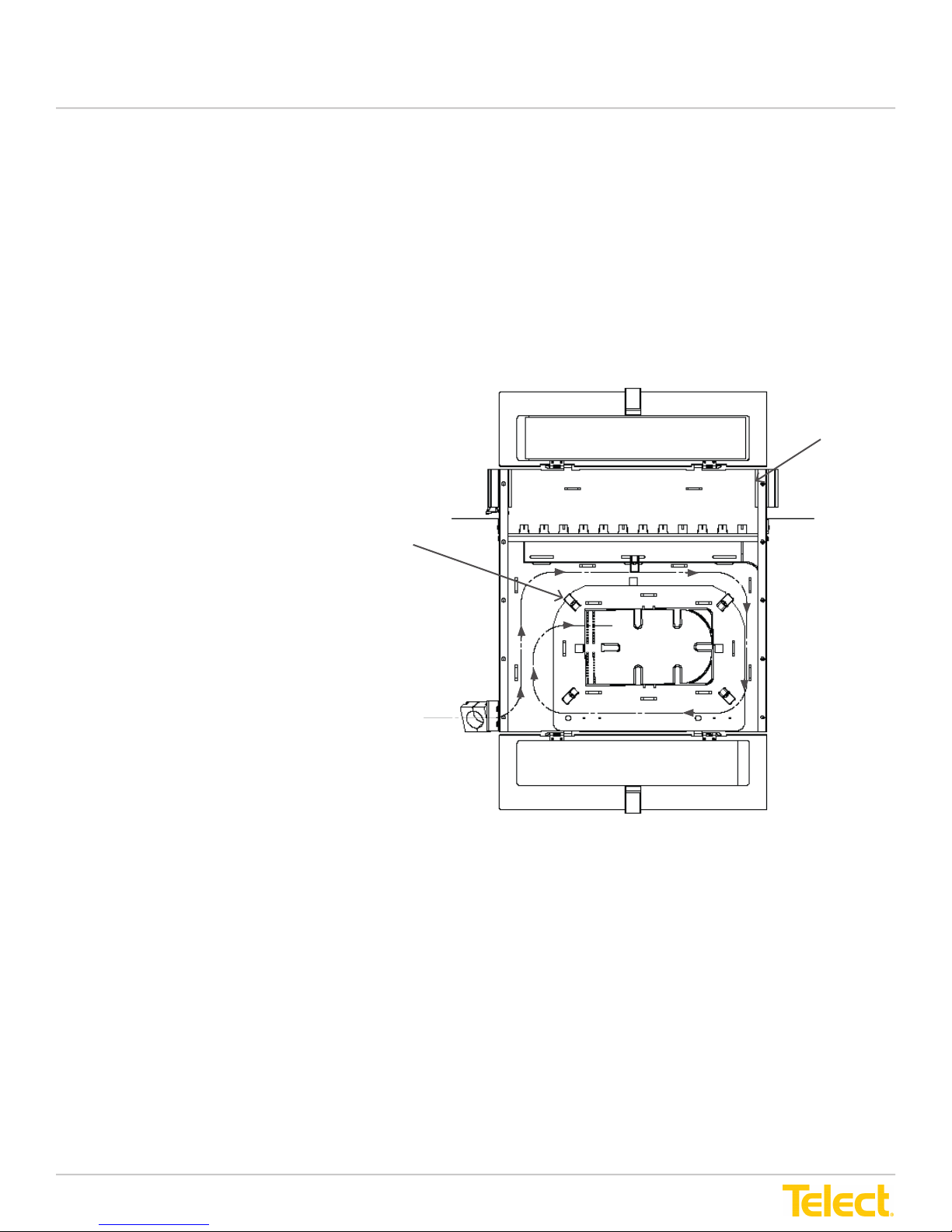
4.1.3 Routing Protected 12 Strand Ribbon Fiber in LTX Panel Slack Storage Area
The installation instructions apply to the LTX 4RU
Refer to
12-strand ribbon bers are protected in subunit cabling within the IFC as it routes to the LTX Panel. At the edge of the
LTX panel the IFC is attached to the rear corner in a cable clamp. After securing the cable, the cable jacket is stripped to
expose subunit cables. Subunit cables route through slack storage within the LTX panel.
NOTE: Perform this procedure for one splice tray at a time, starting with the bottom tray and working up.
1. At the LTX panel, measure an
2. Strip away IFC sheathing to expose
3. Route three (3) subunit cables around
4. If desired, use velcro bandings to
5. Proceed to Section 4.1.4,
Figure 4-2
additional 83 inches of IFC cabling.
83 inches of subunits from the IFC.
Cuts should be made square. Each
subunit cable contains 12-ribbon
ber strands.
NOTE: Be careful not to damage
ribbon bers.
the routing spools that protect splice
trays in the rear of the LTX panel.
secure subunit cables to metal
tie-downs on the splice tray platform
and along sides in the rear of the
LTX panel.
Ribbon Fibers in the Splice Tray
for this procedure.
Install
.
LTX Panel Top View
Front
Routing
Spool
IFC Cable
Routing
© Telect, Inc. All rights reserved. 148326 12.20.16 v2
1.509.926.6000 :: telect.com
Figure 4-2 - Routing Protected 12-Strand Ribbon Fiber through
LTX Panel Slack Storage Area
26
Page 27
LTX Patch and Splice Panel
Installation Guide
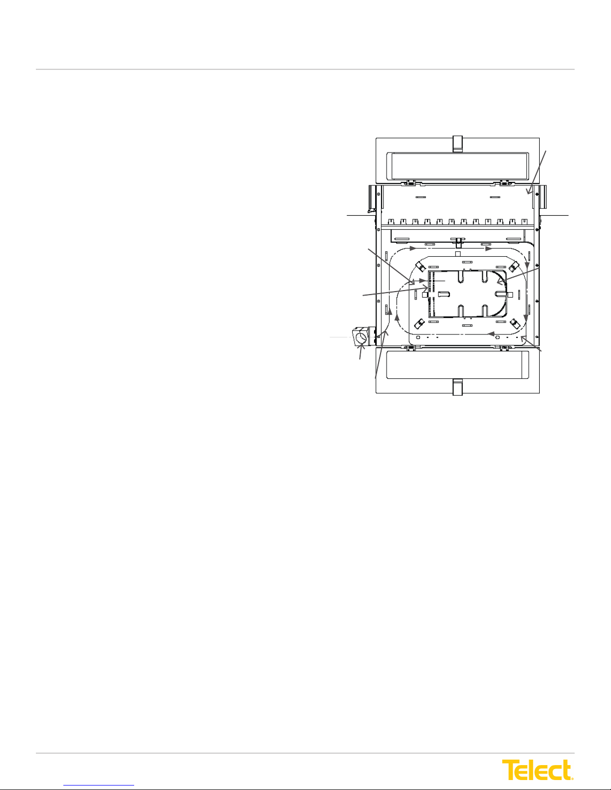
4.1.4 Installing Ribbon Fibers in the Splice Tray
Refer to
1. After routing subunits in the LTX panel, measure from the end
2. Use a utility knife to cut the subunit on the location marked
3. Use lint free wipes and gel cleaner to remove all gel and
4. Remove plastic cover from the splice tray.
5. Clamp subunit to edge of splice tray entrance.
6. Run individual stranded bers through separate entrance
Figure 4-3
of the subunit back 24 inches and mark with a marker.
exposing 24 inches of 900 µm ribbon bers.
thoroughly clean the ribbon bers.
slots and loosely route exposed ribbon bers through the
tray beneath the protective tabs along the edge of the
splice tray. Keep bers together in the same order as they
entered the tray and route them around the end of the sleeve
holders. If needed, band bers together with velcro ties at
protective tabs.
for this procedure.
NOTE: Take care to maintain a bend radius of no less than 7
inches as the bers route through the tray.
7. Continue to route the bers to one of the bottom sleeve
holders. Place six individual bers in individual grooved
sleeves in the sleeve holder. Fiber should not run all the way
through the sleeve holder but should stop about halfway in the
sleeve holder.
8. Record ber designation information on designation card
located in the clear cover on the door.
9. Repeat Steps 5 - 8 to route the remaining six individual bers
into the top sleeve holder (bers route about halfway in the
holder).
Fibers remain in this position until splicing.
10. Repeat Steps 1 - 9 to route bers individually for the next
two subunits.
11. Replace plastic cover on splice tray.
12. Proceed to Section 4.1.5, Install Pigtail Fiber Connectors.
Figure 4-3 - Installing Ribbon Fibers in the Splice Tray
LTX Panel Top View
Front
Subunits
to Ribbon
Fibers
Splice
Tray
Entrance
Slots
IFC Cable
Cable
Clamp
Subunit
Routing
IFC Routing for left entrance
Note: When IFC entrance is on the right side, in order
to maximize the effectiveness of the LTX module, it is
recommended to change the exit side of the pigtails
towards splicing area.
Designation Card
Rear
© Telect, Inc. All rights reserved. 148326 12.20.16 v2
1.509.926.6000 :: telect.com
27
Page 28
LTX Patch and Splice Panel
Installation Guide
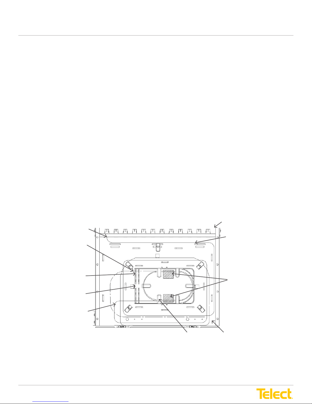
4.1.5 Routing Pigtail Fibers in the Splice Tray
The installation instructions apply to the LTX 4RU
Refer to Figure 4-4 for this procedure
Pigtail bers route from connectors that connect adapters to jumpers and patch the bers in the LTX panel.
Refer to Section 4.1.5, Install Pigtail Fiber Connectors before completing this section.
NOTE: Ensure designation label is marked with correct designation information.
1. Route a pigtail ber from connector into the splice tray at the opposite corner entrance from where IFC bers route
into the tray.
NOTE: Keep track of individual bers entering the splice tray. Place each individual ber from the rst 12 bers
entering the tray into separate entrance slots. Place the next 12 bers on top of the rst twelve and the third group
of 12 bers on top of the rst and second groups. Up to 36 bers can enter the tray (three bers will end up being in
each entry slot.)
2. Loosely route each individual pigtail ber through the tray maintaining a bend radius of no less than 7 inches. Keep
the ber beneath the protective tabs along the edge of the splice tray.
3. Route the ber through the tray, around the sleeve holder position and into the corresponding sleeve holder about
halfway so that ber ends do not touch the IF bers.
4. For each ber routed into the tray, repeat this section (until 36 pigtail bers have been routed into this splice tray).
As bers are added, record locations on the designation label attached to the panel door.
5. After completing this section, repeat Section 4.1.4, Route Protected 12-Strand Ribbon Fiber in LTX Panel Slack
Area, and then Section 4.1.5, Install Ribbon Fibers in the Splice Tray, and then this section (Section 4.1.6, Route
Pigtail Fibers in the Splice Tray) again for the next splice trays working from lowest tray to the highest tray.
LTX Panel
Top View
Pigtail Fiber
Connectors
Route Pigtail
Fiber into
Splice Tray
Entrance
Slots
Splice Tray
Ribbon Fibers Route in
and through Splice Tray
to Sleeve Holders
Front (partial)
Pigtail Fiber
Routing in the
LTX Panel
Route Fibers in
Splice Tray to
Sleeve Holders
Figure 4-4 - Routing Pigtail Fibers in the 4RU Splice Tray
© Telect, Inc. All rights reserved. 148326 12.20.16 v2
1.509.926.6000 :: telect.com
Protective Tab
28
LTX Panel
Top View
Rear
Page 29
LTX Patch and Splice Panel
Installation Guide
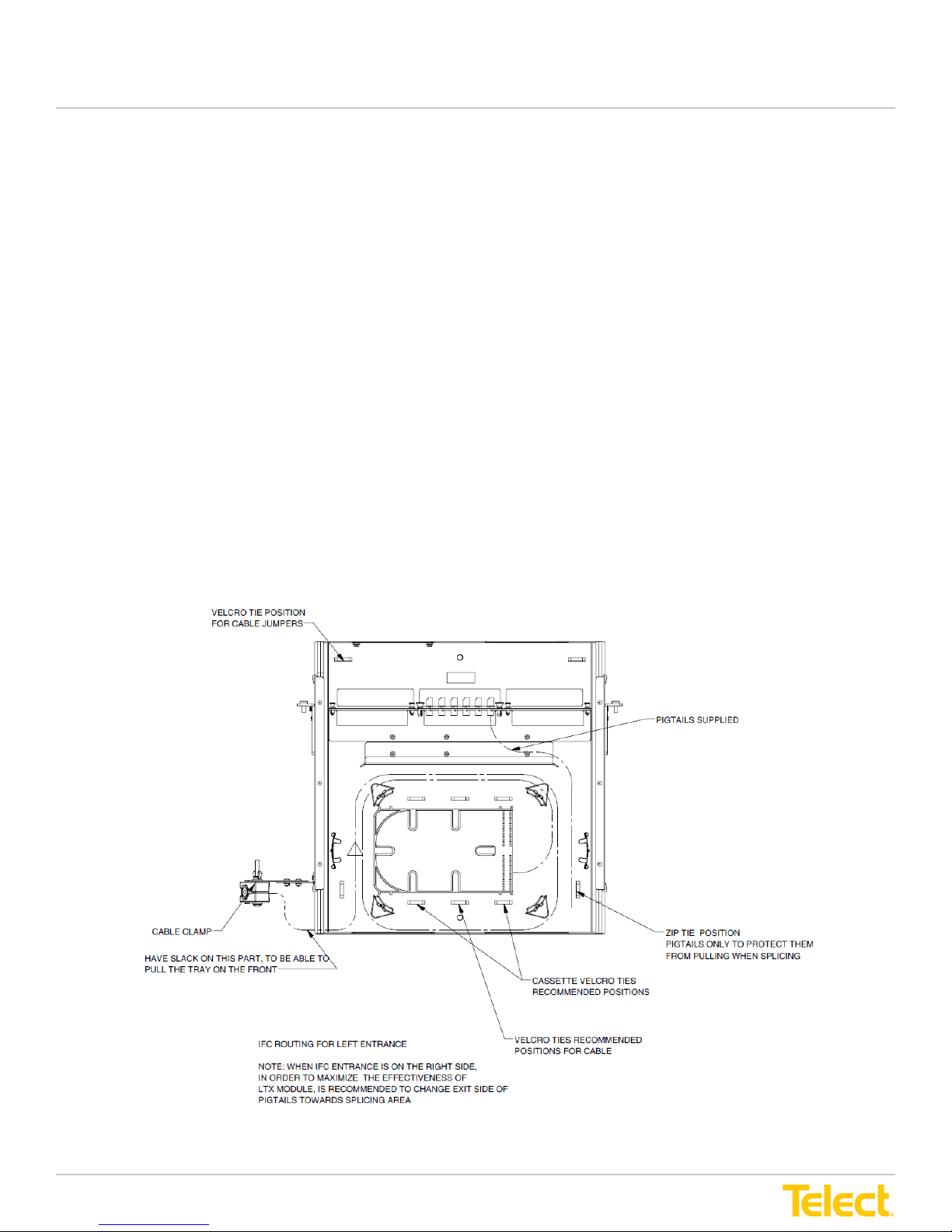
The installation instructions apply to the LTX 2RU
Refer to Figure 4-4-1 for this procedure
Pigtail bers route from connectors that connect adapters to jumpers and patch the bers in the LTX panel.
Refer to Section 4.1.5, Install Pigtail Fiber Connectors before completing this section.
NOTE: Ensure designation label is marked with correct designation information.
1. Route a pigtail ber from connector into the splice tray at the opposite corner entrance from where IFC bers route
into the tray.
NOTE: Keep track of individual bers entering the splice tray. Place each individual ber from the rst 12 bers
entering the tray into separate entrance slots. Place the next 12 bers on top of the rst twelve and the third group
of 12 bers on top of the rst and second groups. Up to 36 bers can enter the tray (three bers will end up being in
each entry slot.)
2. Loosely route each individual pigtail ber through the tray maintaining a bend radius of no less than 7 inches. Keep
the ber beneath the protective tabs along the edge of the splice tray.
3. Route the ber through the tray around the sleeve holder position and into the corresponding sleeve holder about
halfway so that ber ends do not touch the IF bers.
4. For each ber routed into the tray, repeat this section (until 36 pigtail bers have been routed into this splice tray).
As bers are added record locations on the designation label attached to the panel door.
5. After completing this section, repeat Section 4.1.4, Route Protected 12-Strand Ribbon Fiber in LTX Panel Slack
Area, and then Section 4.1.5, Install Ribbon Fibers in the Splice Tray, and then this section (Section 4.1.6, Route
Pigtail Fibers in the Splice Tray) again for the next splice trays working from lowest tray to the highest tray.
Figure 4-4-1 - Routing Pigtail Fibers in the 2RU Splice Tray
© Telect, Inc. All rights reserved. 148326 12.20.16 v2
1.509.926.6000 :: telect.com
29
Page 30
LTX Patch and Splice Panel
Installation Guide
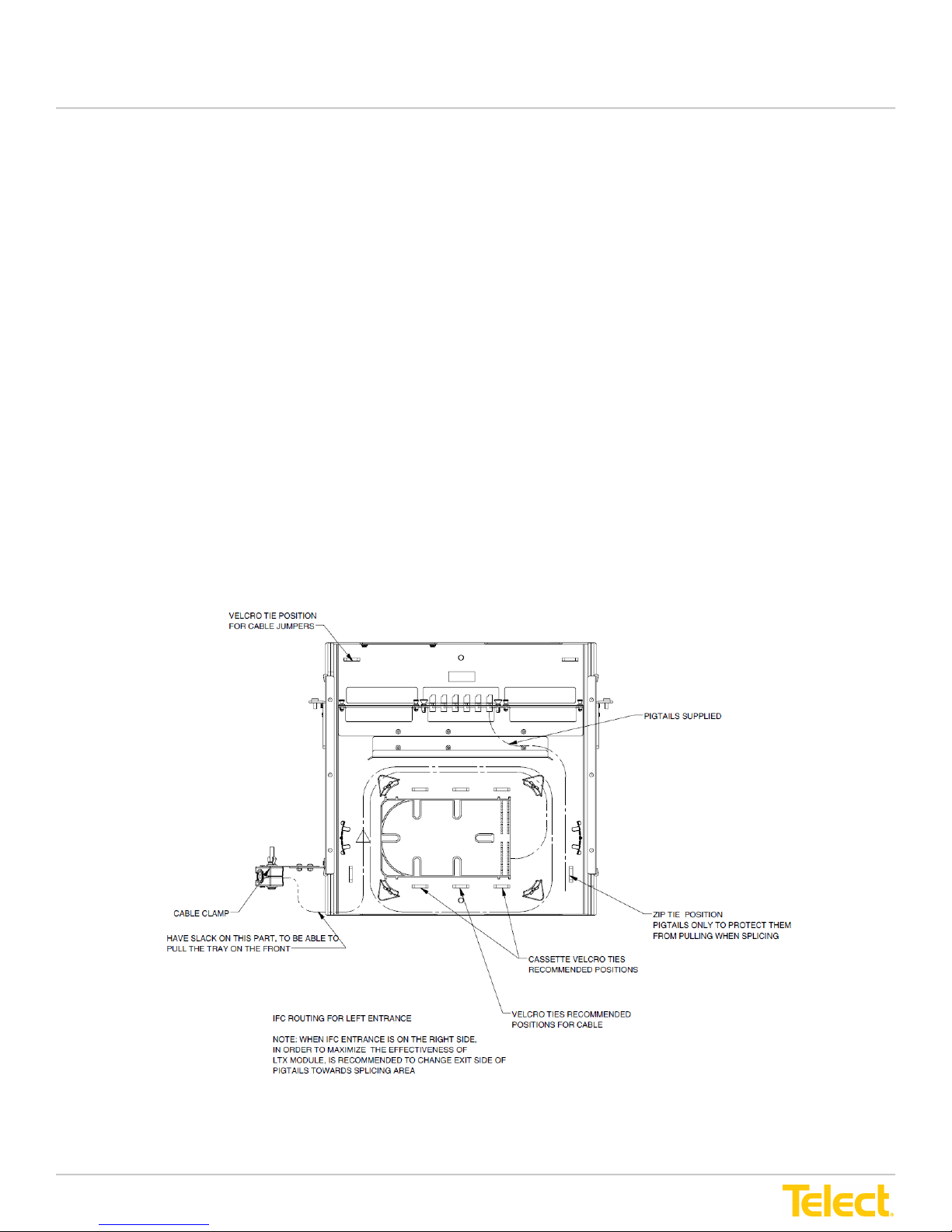
The installation instructions apply to the LTX 1RU
Refer to Figure 4-4-2 for this procedure
Pigtail bers route from connectors that connect adapters to jumpers and patch the bers in the LTX panel.
Refer to Section 4.1.5, Install Pigtail Fiber Connectors before completing this section.
NOTE: Ensure designation label is marked with correct designation information.
1. Route a pigtail ber from connector into the splice tray at the opposite corner entrance from where IFC bers route
into the tray.
NOTE: Keep track of individual bers entering the splice tray. Place each individual ber from the rst 12 bers
entering the tray into separate entrance slots. Place the next 12 bers on top of the rst twelve and the third group
of 12 bers on top of the rst and second groups. Up to 36 bers can enter the tray (three bers will end up being in
each entry slot.)
2. Loosely route each individual pigtail ber through the tray maintaining a bend radius of no less than 7 inches. Keep
the ber beneath the protective tabs along the edge of the splice tray.
3. Route the ber through the tray around the sleeve holder position and into the corresponding sleeve holder about
halfway so that ber ends do not touch the IF bers.
4. For each ber routed into the tray, repeat this section (until 36 pigtail bers have been routed into this splice tray).
As bers are added record locations on the designation label attached to the panel door.
5. After completing this section, repeat Section 4.1.4, Route Protected 12-Strand Ribbon Fiber in LTX Panel Slack
Area, and then Section 4.1.5, Install Ribbon Fibers in the Splice Tray, and then this section (Section 4.1.6, Route
Pigtail Fibers in the Splice Tray) again for the next splice trays working from lowest tray to the highest tray.
Figure 4-4-2 - Routing Pigtail Fibers in the 1RU Splice Tray
© Telect, Inc. All rights reserved. 148326 12.20.16 v2
1.509.926.6000 :: telect.com
30
Page 31

LTX Patch and Splice Panel
Installation Guide
4.2 Splice and Route Fibers
Splice bers in each splice tray starting with the bottom tray and working up.
1. Rotate the tray platform out from the inside of the rear of the LTX panel.
2. Remove velcro banding and carefully set the top spice trays to the side so that the bottom tray is easily accessible.
NOTE: Use care to maintain bend radius and not damage bers.
3. Remove top plastic cover on the tray.
4. Carefully remove ribbon bers and pigtail strands from one group of sleeve holders.
5. Lay bers over the edge of the splice tray.
6. For each pair of bers to be spliced:
a. Clean each exposed ber with lint free wipes and denatured alcohol. Ensure they are free of gel, lint
and debris.
b. Splice bers according to mass fusion splice machine manufacturer instructions.
c. After splicing, inspect splice for aws. If needed, cut and re-splice before adding splice sleeve.
7. Reroute the two-spliced ribbons back in the splice tray to the splice sleeve holder in the same order as originally
placed. Refer to Section 4.1.4,
the Splice Tray
8. Repeat Steps 4 - 7 to splice each ribbon pair.
9. When splicing is complete: replace cover, set next tray on top, snap top tray tab into lower tray slot.
10. Repeat Steps 3 - 9 to splice bers in the remaining trays.
for routing instructions.
Install Ribbon Fibers in the Splice Tray
and Section 4.1.5
, Route Pigtail Fibers to
4.3 Connect Fiber Jumpers to the Patch Panel
CAUTION! Do not connect bers to the adapters before all pigtail bers have been installed and spliced at the
splice tray.
CAUTION! Wear safety glasses while working with exposed ber optic ber. Do not touch eyes while working
with ber optic bers.
© Telect, Inc. All rights reserved. 148326 12.20.16 v2
1.509.926.6000 :: telect.com
31
Page 32
LTX Patch and Splice Panel
Installation Guide
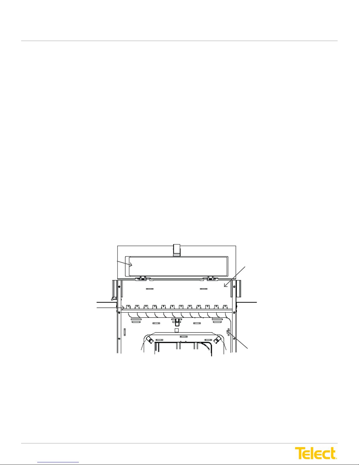
Refer to Figure 4-5, Figure 4-5-1 & 4-5-2 for this procedure.
Fiber jumpers enter the LTX patch and splice panel from front corners and attach to adapters following the number
scheme designated on the designation label mounted on the front door.
After connectors with pigtail bers have been installed and bers have been spliced:
1. Locate adapter designation number on the designation card located on the front door of the LTX panel. Record
designation information.
2. Remove protective dust cap from the patch plate adapter port for the ber jumper being installed.
NOTE: To protect bers, work with one ber jumper at a time. Only remove the dust cap for the ber jumper
being installed.
3. Clean adapter port with oil free “canned” compressed air to remove any dust that has accummulated there.
4. Remove the protective cover from the ber jumper by pulling it straight out.
5. Inspect the end of the ber jumper for any dust or debris. If needed, clean the ber with lint wipes and a commercial
solution formulated for cleaning ber surfaces or a reagent-grade ethyl alcohol to remove particles.
6. Use a second dry wipe to dry the ber.
7. Inspect again to ensure ber end is clean; repeat Steps 5 - 6 if needed.
NOTE: After conrming the ber jumper end is clean, do not wipe the ber or allow it to touch anything before
installing it in the adapter.
8. Insert the clean, dry ber into the adapter port.
9. Repeat Steps 1 - 8 to install remaining ber jumpers to adapters in the patch plate.
Patch Plate
Adapter Ports
Front
Door
Figure 4-5 - Connecting Fiber Jumpers to the 4RU Patch Panel
Designation Card
LTX Panel
Top View
Front
LTX Panel
Top View
Rear (partial)
© Telect, Inc. All rights reserved. 148326 12.20.16 v2
1.509.926.6000 :: telect.com
32
Page 33
LTX Patch and Splice Panel
Installation Guide
Front Door
Designation Card
Patch Plate
Adapter Ports
LTX Panel Top
View Front
Patch Plate
Adapter Ports
LTX Panel
Top View
Rear (partial)
4-5-1 - Connecting Fiber Jumpers to the 2RU Patch Panel
LTX Panel Top
View Front
Designation Card
4-5-2 - Connecting Fiber Jumpers to the 1RU Patch Panel
© Telect, Inc. All rights reserved. 148326 12.20.16 v2
1.509.926.6000 :: telect.com
LTX Panel
Top View
Rear (partial)
33
Page 34
LTX Patch and Splice Panel
Installation Guide
Chapter 5: Service
5.1 Owner Maintenance
The Telect LTX patch and splice panels do not require any preventative maintenance. If equipment is not working
properly, contact technical support and be advised of the following warning/caution/alert.
WARNING! To avoid eye damage or blindness, never look directly into bers or connections.
CAUTION! Wear safety glasses while working with exposed ber optic ber. Do not touch eyes while
working with ber optic bers.
ALERT! This product must be installed and maintained by qualied technicians.
5.1.1 High Insertion Loss and the Importance of Cleaning Connectors and Adapters
The major causes for poor performance (high insertion loss) are:
• Attenuation due to too sharp or too many close radius bends in the fiber cable
• Loose connections
• Dirty connectors or adapters
If you experience insertion loss greater than 2.5 dB, check for sharp bends and loose connections. Clean all polished
ferrules on pigtails and both ends of the patch cord or jumper.
Though Telect includes dust caps with all adapters and connectors, it is not always possible to ensure that ber ferrules
stay clean. If you need to clean connectors and adapters, Telect recommends a commercially available system or
solution. Special formulation for cleaning ber ferrules allows the commercial solvent to stay liquid long enough to dissolve
impurities quickly and thoroughly, yet evaporate quickly after wiping dry. Always allow the ferrules to air dry thoroughly
before reconnecting. “Canned air” can be used to clean away debris initially, but do not use an aerosol after cleaning
polished surfaces. Most aerosols contain contaminants.
If a commercial solution is not available, a reagent-grade ethyl alcohol, nominally USP > 99% can be used, available
at pharmacies.
Remove both connectors from the adapter:
1. Blow compressed gas through the adapter.
2. Moisten a lint-free wipe with the ethyl alcohol.
3. Wipe completely around the ferrule of the connector twice. Repeat with a dry wipe.
4. Moisten the center area of a third wipe and pass the face of the ferrule from the moistened area outward toward the
dry area.
5. Repeat Step 4.
6. Allow ferrule to air dry. After completing this step, do not wipe the ferrule or allow it to touch anything before inserting
the ferrule into the adapter. Do not cover with a dust cap.
7. Insert the connector into the adapter.
8. Repeat Steps 1 through 7 for each connector.
© Telect, Inc. All rights reserved. 148326 12.20.16 v2
1.509.926.6000 :: telect.com
34
Page 35

LTX Patch and Splice Panel
Installation Guide
5.2 Technical Support
By e-mail: [email protected]
By phone: 1-509-926-6000
5.3 In-Warranty Service
Contact your Telect equipment distributor, or call Telect Support to talk with a Customer Service Representative. Telect will
repair or replace defective products within the limits of the warranty. See “Repacking for Shipment” in this section.
NOTE: Call a Customer Service Representative for a Return Material Authorization (RMA) before returning any equipment.
5.4 Out-of-Warranty Service
The procedure for out-of-warranty service is the same as for in-warranty service; however, Telect charges a processing
fee. You must submit a Purchase Order along with a Return Material Authorization (RMA) before returning equipment.
Call Telect for assistance in acquiring these forms.
The processing fee guarantees a repair estimate and is credited against actual material and labor costs.
5.5 Repackage for Shipment
Tag the equipment showing owner’s name, address, and telephone number, together with a detailed description of
the problem.
Use the original shipping container if possible. If you do not have it, package the equipment in a way to prevent shipping
damage. Include the RMA inside the container and legibly print the RMA number on the outside of the package, near the
shipping address.
Insure the package.
NOTE: Telect is not liable for shipping damage.
© Telect, Inc. All rights reserved. 148326 12.20.16 v2
1.509.926.6000 :: telect.com
35
 Loading...