

Telect ELF-1008-1100, ELF-1008-1800, ELF-9704-1119, ELF-3004-1800, ELF-3206-1200 User Manual
...Page 1
ELF System
Copper / Fiber :: ELF Family
User Manual
Applys to : ELF-1008-1100 :: ELF-1008-1200 :: ELF-1008-1800 :: ELF-3006-1100 :: ELF-3006-1800
ELF-9704-1119 :: ELF-3004-1800 :: ELF-3206-1200 :: ELF-3206-1900 :: ELF-PC12-SC00
ELF-9716-1900 :: ELF-9716-1700 :: ELF-0005-0001 :: ELF-PC12-FC00 :: ELF-SP12-SCPT
ELF-SP12-FCPT :: ELF-PC12-SA00 :: ELF-SP12-SAPT
© Telect, Inc., All Rights Reserved, 124317-10 A0
1.509.926.6000 :: telect.com
Page 2

ELF System
Copper / Fiber :: ELF Family
Table of Contents
Chapter 1: Descriptions ........................................................................................................1
1.1 ELF Copper/Fiber System ..............................................................................................1
1.2 ELF Modules ...................................................................................................................1
1.3 ELF Mounting Options .................................................................................................... 5
1.3.1 ELF Chassis (Model ELF-0000-2400).....................................................................5
1.3.2 Wall-Mount ELF Chassis Bracket (ELF-0000-0900) ...............................................7
1.3.3 ELF Wall Bracket (Model ELF-0000-0600) ...........................................................10
1.3.4 ELF Lockable Wall-Mount Enclosure (Model ELF-0000-0800) ............................. 11
1.4 System-Level Applications ............................................................................................ 13
1.5 Installation Considerations ............................................................................................13
1.5.1 Location and Space ..............................................................................................13
1.5.2 Tools and Equipment ............................................................................................. 13
1.5.3 Inspection .............................................................................................................. 14
1.5.4 Technical Support (USA) ....................................................................................... 14
1.6 Specications ................................................................................................................14
Chapter 2: ELF DS1 Modules ............................................................................................. 17
2.1 ELF 8-Termination DSX-1, Wire-Wrap I/O (Model ELF-1008-1100) ............................. 17
2.2 ELF 8-Termination DSX-1, BNC I/O (Model 1008-1200) .............................................. 19
2.3 ELF 8-Termination DSX-1, RJ48C I/O (Model ELF-1008-1800) ................................... 21
2.4 ELF 6-Termination DSX-1, Wire-Wrap I/O (Model ELF-3006-1100) ............................. 23
2.5 ELF 6-Termination DSX-1, RJ48C I/O (Model ELF-3006-1800) ................................... 24
2.6 ELF 4-Circuit DNI-1, Wire-Wrap I/O to RJ48C I/O (Model ELF-9704-1119) .................25
2.7 ELF 4-Circuit DNI-1, RJ48C I/O to RJ48C I/O (Model ELF-3004-1800) .......................27
Chapter 3: ELF DS3 Modules ............................................................................................. 29
3.1 ELF 2-Termination DSX-3, Rear BNC I/O (Model ELF-3206-1200) .............................29
3.2 ELF 1-Termination DSX-3, TFA BNC I/O (Model ELF-3206-1900) ............................... 31
Chapter 4: ELF Fiber Modules ............................................................................................33
4.1 ELF Fiber Patch Modules (Model Series ELF-PC12) ................................................... 33
4.2 ELF Fiber Splice/Patch Modules (Model Series ELF-SP12) ........................................34
Chapter 5: ELF Multi-Purpose Modules ..............................................................................37
5.1 ELF RJ45C to RJ45C Patch Module (Model ELF-9716-1900) ..................................... 38
5.2 ELF RJ45-IDC Patch Module (Model ELF-9716-1700) ................................................39
5.3 ELF 12 x 4 Alarm Pin Block Module (Model ELF-0005-0001) ......................................40
Chapter 6: Service .............................................................................................................. 41
6.1 Owner Maintenance ......................................................................................................41
6.2 Service .......................................................................................................................... 41
6.2.1 In-Warranty Service ..............................................................................................41
6.2.2 Out-Of-Warranty Service .......................................................................................41
6.3 Repacking For Shipment ..............................................................................................41
Chapter 7: Accessories ....................................................................................................... 42
© Telect, Inc., All Rights Reserved, 124317-10 A0
1.509.926.6000 :: telect.com
ii
Page 3

ELF System
Copper / Fiber :: ELF Family
List of Figures
Figure 1 - ELF Chassis Mounting Options ............................................................................ 6
Figure 2 - Installing ELF Chassis on a Rack .........................................................................7
Figure 3 - Grounding an ELF Chassis ..................................................................................7
Figure 4 - Bracket .................................................................................................................7
Figure 5 - Wall-Mount ELF Chassis Bracket Dimensions ..................................................... 8
Figure 6 - Wall-Mount ELF Chassis Bracket Installation.......................................................9
Figure 7 - ELF Wall Bracket Dimensions ............................................................................10
Figure 8 - Typical ELF Wall Bracket Installation .................................................................10
Figure 9 - ELF Lockable Wall-Mount Enclosure ................................................................. 11
Figure 10 - ELF Lockable Wall-Mount Dimensions.............................................................12
Figure 11 - Model ELF-1008-1100 Dimensions ..................................................................17
Figure 12 - Model ELF-1008-1100 Reference Schematic .................................................. 18
Figure 13 - Model 1008-1200 Dimensions ..........................................................................19
Figure 14 - Model 1008-1200 Reference Schematic .......................................................... 20
Figure 15 - Model ELF-1008-1800 Dimensions .................................................................. 21
Figure 16 - Model ELF-1008-1800 Reference Schematic ..................................................22
Figure 17 - Model ELF-3006-1100 Dimensions .................................................................. 23
Figure 18 - Model ELF-3006-1100 Reference Schematic .................................................. 23
Figure 19 - Model ELF-3006-1800 Dimensions .................................................................. 24
Figure 20 - Model ELF-3006-1800 Reference Schematic ..................................................24
Figure 21 - Model ELF-9704-1119 Dimensions ..................................................................25
Figure 22 - Model ELF-9704-1119 Reference Schematic ...................................................26
Figure 23 - Model ELF-3004-1800 Dimensions .................................................................. 27
Figure 24 - Model ELF-3004-1800 Reference Schematic ..................................................27
Figure 25 - Model ELF-3206-1200 Dimensions .................................................................. 29
Figure 26 - Model ELF-3206-1200 Reference Schematic ..................................................30
Figure 27 - Model ELF-3206-1900 Dimensions .................................................................. 31
Figure 28 - Model ELF-3206-1900 Reference Schematic ..................................................31
Figure 29 - ELF-PC12-SC00 ..............................................................................................33
Figure 30 - ELF Patch Module (Model ELF-PC12-SCxx, Typical Cabling .......................... 34
Figure 31 - Model Series ELF-SP12 Parts & Dimensions ..................................................34
Figure 32 - Splice Cassette ................................................................................................35
Figure 33 - Subunit Entrance Compartment ....................................................................... 35
Figure 34 - ELF Splice/Patch Module ................................................................................. 36
Figure 35 - Model ELF-9716-1900 Parts & Dimensions ..................................................... 38
Figure 36 - Model ELF-9716-1900 Schematic .................................................................... 38
Figure 37 - Model ELF-9716-1700 Parts & Dimensions ..................................................... 39
Figure 38 - Model ELF-9716-1700 Schematic .................................................................... 39
Figure 39 - Example of Model ELF-9716-1700 nished cable and wiring .......................... 40
Figure 40 - Model ELF-0005-0001 Parts & Dimensions ..................................................... 40
© Telect, Inc., All Rights Reserved, 124317-10 A0
1.509.926.6000 :: telect.com
iii
Page 4

ELF System
Copper / Fiber :: ELF Family
Chapter 1: Descriptions
1.1 ELF Copper/Fiber System
Telect’s ELF System is a small “edge” connection system for use in locations where equipment density — maximum
density with simplied monitoring — is important. The ELF System is ideal for a 3G, 4G, LTE wireless network at
a base transceiver station (BTS), customer premises, controlled environment vault, co-location, or at any remote
network terminal.
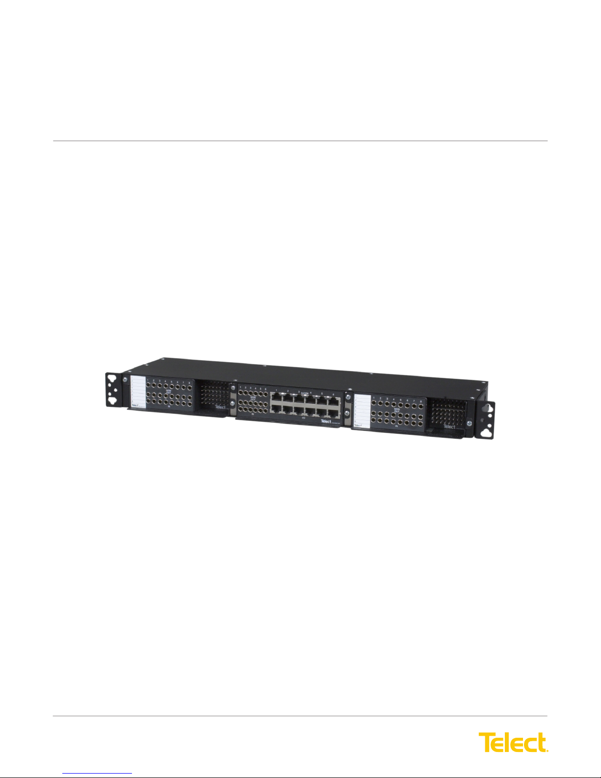
All ELF Systems consists of a chassis, wall brackets, or wall enclosures with DSX-1, DNI, DSX-3,
Fiber, and/or Ethernet/Data modules:
• ELF Chassis t equipment cabinets, 19-in. or 23-in. EIA/WECO racks, or Telect’s Wall-Mount ELF Chassis
Bracket. Each 1RU (1RU = 1.75 in.) chassis handles up to three, rear- and/or front-access ELF modules.
DSX-1, DSX-3, ber, and other ELF modules can be mixed in the same chassis.
• Single-Module ELF Wall Brackets mount to the walls. Each bracket accommodates one total front-access
ELF module
• Single-Module ELF Wall enclosures include a lockable access door. The enclosure mounts to the wall and
accommodates one rear- and/or front-access ELF module. Ideal for a Fiber ELF module.
All chassis, brackets, and enclosures include shield ground pins for ITU G.703 compliance. ELF
modules are passive devices and do not require power. All chassis, enclosure, brackets, and
modules are mainly black.
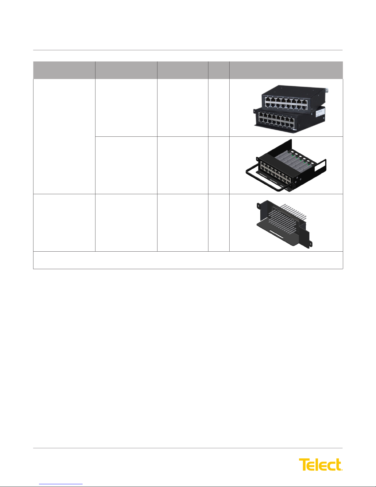
1.2 ELF Modules
The cover shows a composite of all ELF modules and mounting options.
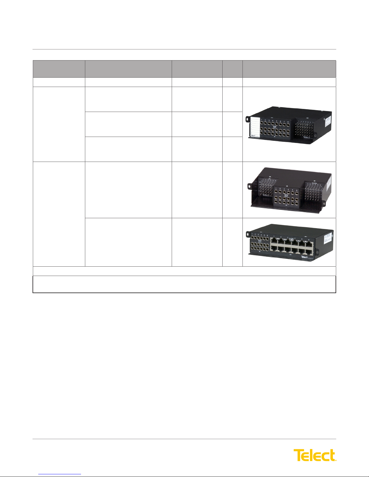
The following identies all ELF DSX1, DSX3, ber, and signal-manager modules offered by Telect, along with
section and page references. Mounting options (chassis and wall mount) are covered in this section.
© Telect, Inc., All Rights Reserved, 124317-10 A0
1.509.926.6000 :: telect.com
1
Page 5
ELF System
Copper / Fiber :: ELF Family
ELF Module Conguration ELF Model
Number
DSX-1
8-Termination REAR — Wire-Wrap I/O
FRONT — Wire-Wrap XC
• 3-Port Bantam Patch Jacks
REAR — BNC I/O
FRONT — Wire-Wrap XC
• 3-Port Bantam Patch Jacks
REAR — RJ48C I/O
FRONT — Wire-Wrap XC
• 3-Port Bantam Patch Jacks
6-Termination
(See Note.)
TOTAL FRONT ACCESS —
• Wire-Wrap I/O
• Wire-Wrap XC
• 3-Port Bantam Patch Jacks
TOTAL FRONT ACCESS —
• RJ48C I/O
• RJ48C XC
• 3-Port Bantam
Patch Jacks
ELF-1008-1100 17
ELF-1008-1200 19
ELF-1008-1800 21
ELF-3006-1100 23
ELF-3006-1800 24
Page Illustration
DNI-1
NOTE: All DS1 and DS3 Total Front Access and 12x4 Alarm Pin Block ELF Modules t Telect’s ELF
Wall Bracket (ELF-000-0600).
© Telect, Inc., All Rights Reserved, 124317-10 A0
1.509.926.6000 :: telect.com
2
Page 6
ELF System
Copper / Fiber :: ELF Family
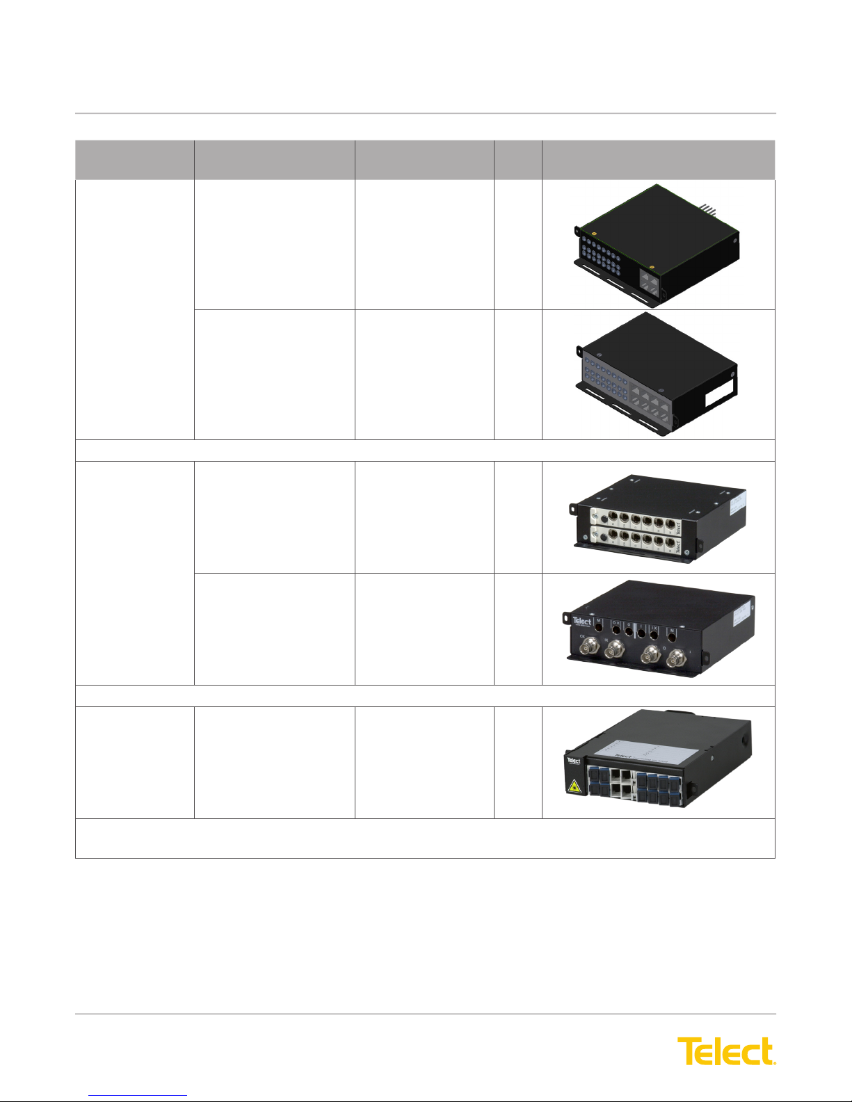
ELF Module Conguration ELF Model
Number
4-Circuit
Interconnect
DSX-3
2-Termination
1-Termination
(See Note.)
REAR —
• Wire-Wrap NE1 I/O
FRONT —
• RJ48C NE2 I/O
• 3-Port Bantam
Patch Jacks for all NEs
TOTAL FRONT
ACCESS(See Note.) —
• RJ48C NE1 I/O
• RJ48C NE2 I/O
• 3-Port Bantam
Patch Jacks for all NEs
REAR —
• BNC I/O & XC
FRONT —
• 6-Port Mini-WECO
Jacks
ELF-9704-1119 25
ELF-3004-1800 27
ELF-3206-1200 29
Page Illustration
TOTAL FRONT AC-
CESS —
• BNC I/O & XC
• 6-Port Mini-WECO
Jacks
Fiber
12-Termination
Patch
NOTE: All DS1 and DS3 Total Front Access and 12x4 Alarm Pin Block ELF Modules t Telect’s ELF
Wall Bracket (ELF-000-0600).
REAR —
• Fiber Jumpers from
NEs
FRONT —
• Fiber Adapters
ELF-3206-1900 31
ELF-PC12-SC00
ELF-PC12-FC00
33
© Telect, Inc., All Rights Reserved, 124317-10 A0
1.509.926.6000 :: telect.com
3
Page 7
ELF System
Copper / Fiber :: ELF Family
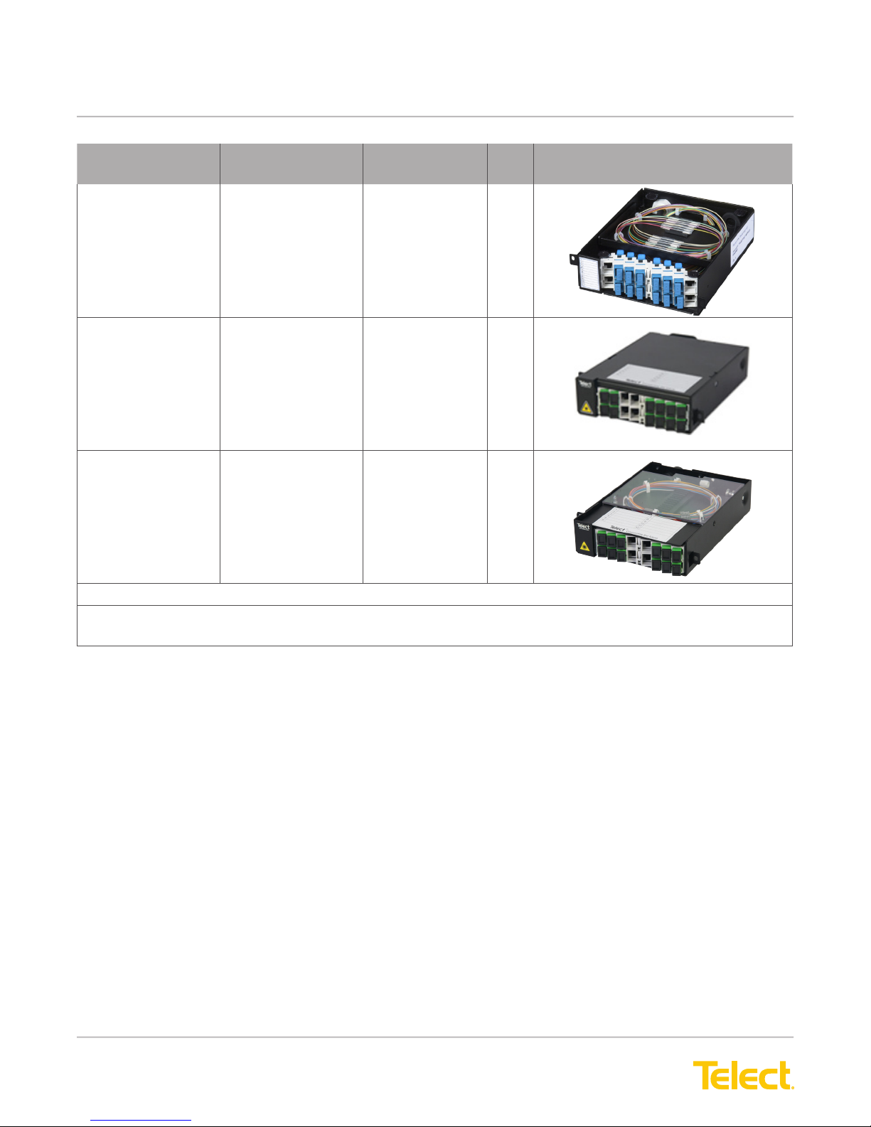
ELF Module Conguration ELF Model
Number
12-Termination
Splice/
Patch
12-Termination
SC-APC
Patch Module
12-Termination
SC/APC
Patch and
Splice Module
REAR —
• Subunit Entrance
FRONT —
• Fiber Adapters
REAR –
• Fiber Jumpers
from NEs
FRONT –
• Fiber Adapters
REAR –
• Subunit Entrance
FRONT –
• Fiber Adapters
ELF-SP12-SCPT
ELF-SP12-FCPT
ELF-PC12-SA00 33
ELF-SP12-SAPT 33
Page Illustration
34
General Purpose Signal Management
NOTE: All DS1 and DS3 Total Front Access and 12x4 Alarm Pin Block ELF Modules t Telect’s ELF
Wall Bracket (ELF-000-0600).
© Telect, Inc., All Rights Reserved, 124317-10 A0
1.509.926.6000 :: telect.com
4
Page 8
ELF System
Copper / Fiber :: ELF Family
ELF Module Conguration ELF Model
Number
16-Circuit
Patch
12 x 4 Alarm
Pin Block
(See Note.)
REAR —
• 16, RJ45Cs
FRONT —
• 16, RJ45Cs
REAR —
• 16 IDC
Punch-Down Blocks
FRONT —
• 16, RJ45s
Bulkhead-Style Pin
Block
ELF-9716-1900 38
ELF-9716-1700 39
ELF-0005-0001 40
Page Illustration
REAR
FRONT
NOTE: All DS1 and DS3 Total Front Access and 12x4 Alarm Pin Block ELF Modules t Telect’s ELF
Wall Bracket (ELF-000-0600).
1.3 ELF Mounting Options
1.3.1 ELF Chassis (Model ELF-0000-2400)
• High-density 1RU chassis accommodates three ELF modules.
• Fully enclosed environment provides robust RF protection.
• Reversible mounting brackets available for 19-in. or 23-in. EIA/WECO racks. (Rack-mounting hardware
included.) Chassis brackets also t Telect’s Wall-Mount ELF Chassis Bracket.
• Total termination capacity per chassis:
− 18 or 24 DSX-1
− 12 DNI
− 3 or 6 DSX-3
− 36 ber splices/patches
− 48 RJ45C-to-RJ45C patches
− 36 alarm interconnects
© Telect, Inc., All Rights Reserved, 124317-10 A0
1.509.926.6000 :: telect.com
5
Page 9
ELF System
Copper / Fiber :: ELF Family
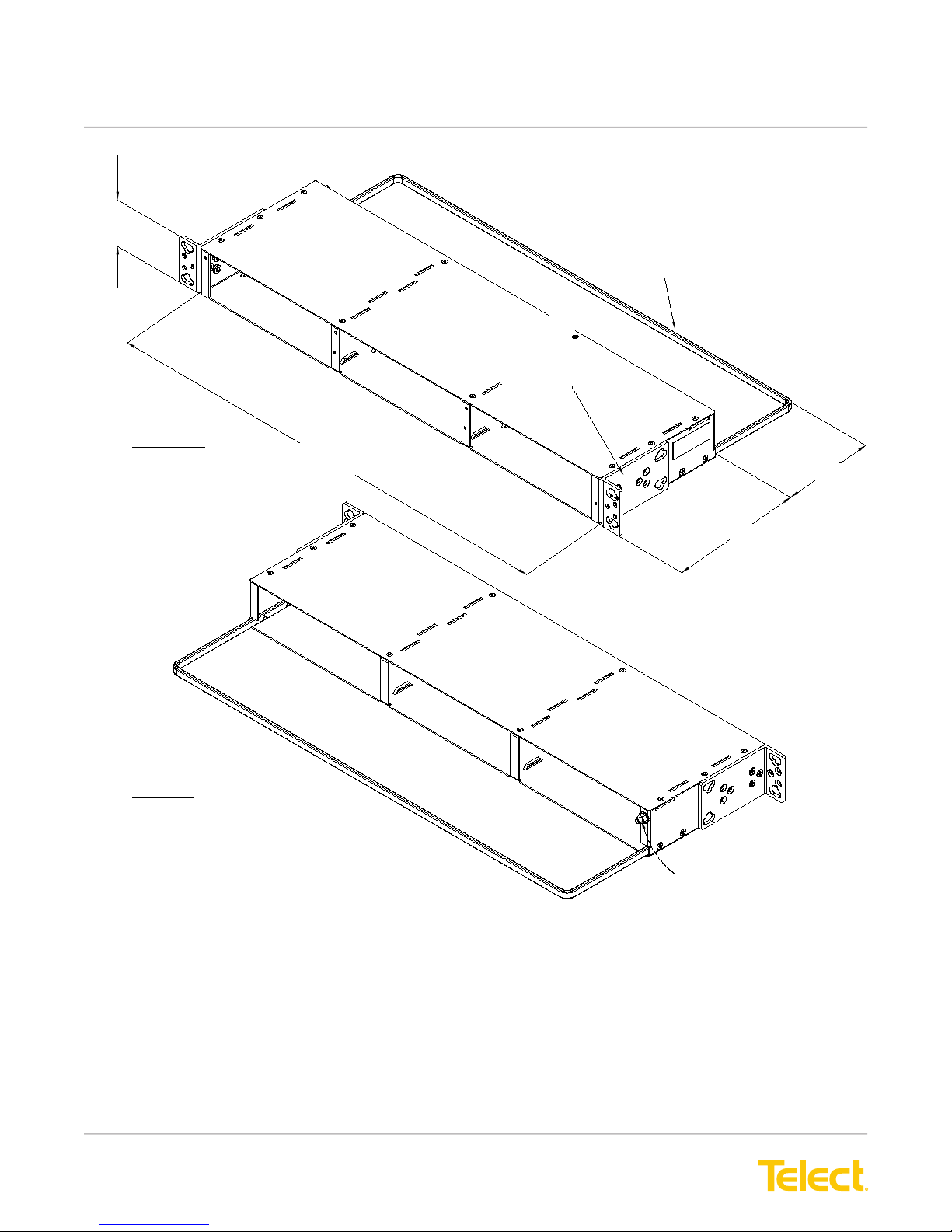
1.73 (44.0)
FRONT VIEW
17.25 (438.2)
Note: Dimensions are in in. (mm)
Removable Cable
Tie-Down Bar
Reversible Rack Brackets
Fit 19-in. or 23-in., EIA- or
WECO-Spaced Racks. Brackets
can be Positioned for Panel Flush
or 1-in. Extended Mounting.
3.5 (88.9)
REAR VIEW
5.00 (127.0)
#8-32 Ground Stud and KEPS Nut
Figure 1 - ELF Chassis Mounting Options
© Telect, Inc., All Rights Reserved, 124317-10 A0
1.509.926.6000 :: telect.com
6
Page 10
ELF System
Copper / Fiber :: ELF Family
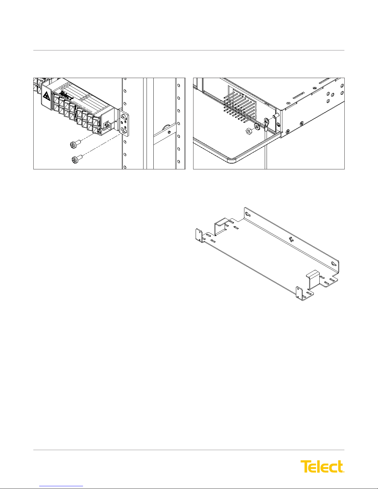
The following illustrations show a typical installation.
Figure 2 - Installing ELF Chassis on a Rack
1.3.2 Wall-Mount ELF Chassis Bracket (ELF-0000-0900)
Telect’s Wall-Mount ELF Chassis Bracket is designed
to hold one ELF Chassis (ELF-0000-2400) against a
wall or side of a cabinet. The chassis bracket allows
an ELF chassis with either rear- and/or front-access
modules to either extend from a wall or cabinet using
a minimum wall “footprint” or to hug the wall or cabinet
with a minimum prole. Wall-mounting hardware is
not included.
Figure 3 - Grounding an ELF Chassis
Figure 4 - Bracket
© Telect, Inc., All Rights Reserved, 124317-10 A0
1.509.926.6000 :: telect.com
7
Page 11

ELF System
Copper / Fiber :: ELF Family
5.30
(134.6)
3.30
(83.8)
0.91 (23.0)
1.25
(31.8)
0.50 (12.7)
0.75 (19.0)
18.71 (475.2)
16.00 (406.4)
3.00 (76.2)
0.25 (6.35)
Outline of ELF Chassis
8.00 (203.2)
0.50 (12.7)
5.00 (127.0)
0.25 (6.35)
0.875 (22.2)
16.00 (406.4)
19.77 (502.2)
18.31 (465.1)
Figure 5 - Wall-Mount ELF Chassis Bracket Dimensions
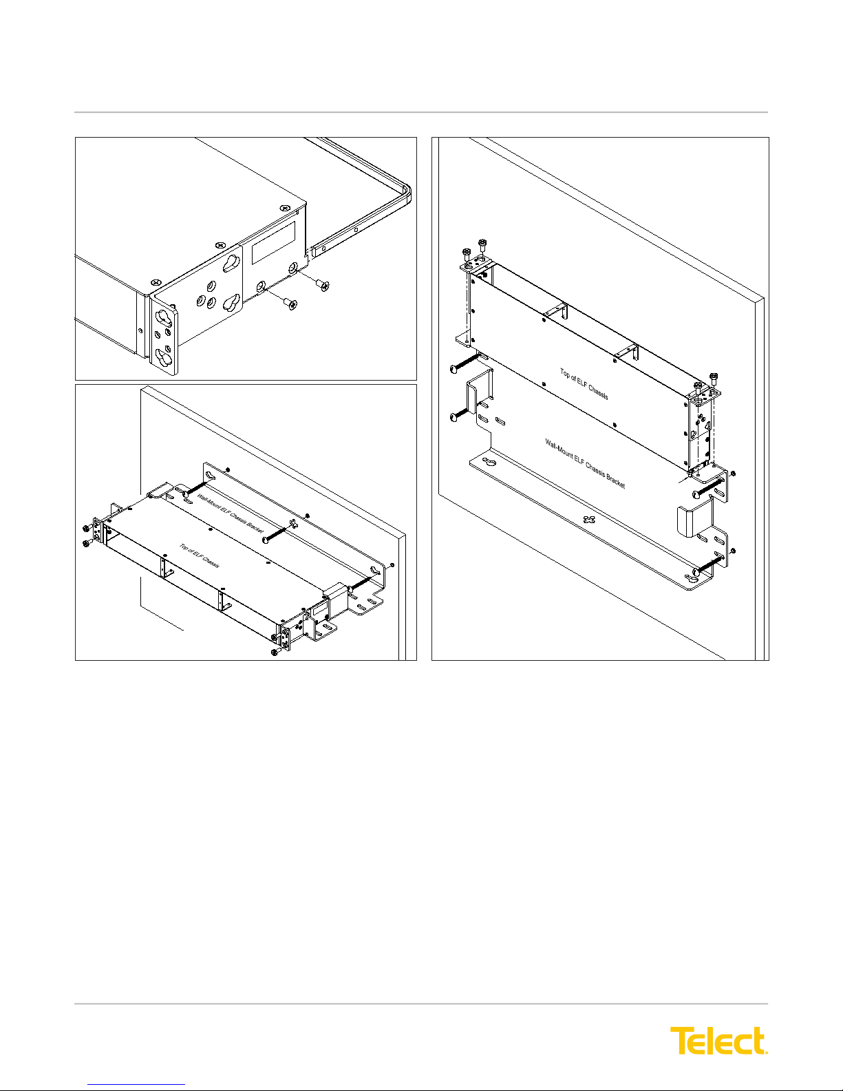
Typical wall installations are shown in the following illustrations. Telect recommends that the tie bar on the rear
of the ELF Chassis be removed when installing in the Wall-Mount ELF Chassis Bracket. Also, when installing
rear access ELF modules, Telect recommends including a minimum 2-ft (600-mm) service loop for any cabling or
wiring intended for the rear of the ELF module(s). Don’t forget to install a ground wire on the ELF Chassis, as
shown on Page 7.
© Telect, Inc., All Rights Reserved, 124317-10 A0
1.509.926.6000 :: telect.com
4.30
(109.2)
8.00
(203.2)
0.95 (24.1)
2.03 (51.5)
8
Page 12
ELF System
Copper / Fiber :: ELF Family
Removing Tie Bar
Rear Tie Bar
Hugging a Wall
Extending from a Wall
Figure 6 - Wall-Mount ELF Chassis Bracket Installation
ELF Chassis
GND Stud
© Telect, Inc., All Rights Reserved, 124317-10 A0
1.509.926.6000 :: telect.com
9
Page 13
ELF System
Copper / Fiber :: ELF Family
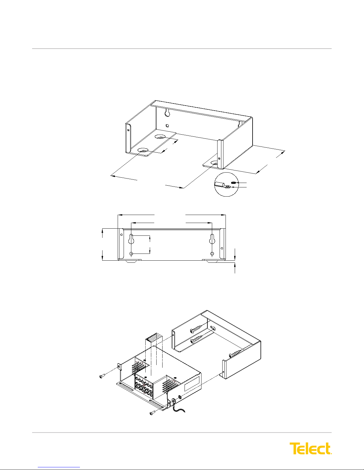
1.3.3 ELF Wall Bracket (Model ELF-0000-0600)
Wall-mount bracket for one, total front access ELF module (ELF-3006-1100, ELF-3006-1800, ELF-3004-1800, or
ELF -0005-0001). Wall-mounting hardware is not included.
Note: Dimensions are in in. (mm)
2.25 (57.2)
4.00 (101.6)
4.50 (114.3)
6.00 (152.4)
4.50 (114.3)
1.78
(54.2)
1.00 (25.4)
Figure 7 - ELF Wall Bracket Dimensions
The following illustration shows a typical installation.
#4 Lockwasher
#4 Lug for 16-14 AWG
Grounding Hardware Included
0.12
(3.0)
Figure 8 - Typical ELF Wall Bracket Installation
© Telect, Inc., All Rights Reserved, 124317-10 A0
1.509.926.6000 :: telect.com
10
Page 14

ELF System
Copper / Fiber :: ELF Family
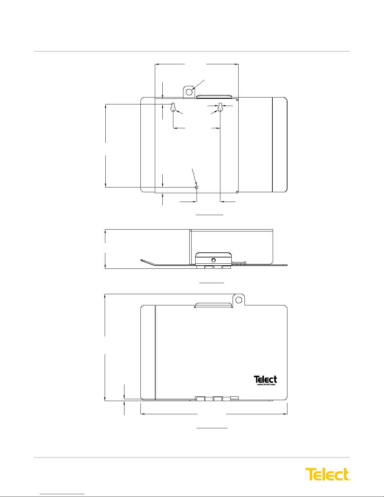
1.3.4 ELF Lockable Wall-Mount Enclosure (Model ELF-0000-0800)
Wall-mount enclosure, designed initially for one ber
ELF module, accommodates any rear-and/or
front-access ELF module. Model ELF-000-0800
includes a lockable access door, ideal for co-locations.
Wall-mounting and grounding hardware are not included.
The following illustration shows a typical installation.
Ground Strap & Lock Washer
are not supplied
ELF Module
(Typical)
Screws are supplied with ELF Module
Mounting screws are not supplied
Figure 9 - ELF Lockable Wall-Mount Enclosure
© Telect, Inc., All Rights Reserved, 124317-10 A0
1.509.926.6000 :: telect.com
11
Page 15
ELF System
Copper / Fiber :: ELF Family
135 (5.31)
Note: Dimensions are in mm (in.)
134
(5.28)
63.5
(2.50)
9.0 (0.35)
9.4 (0.37)
10 (0.39) Dia.
4.6 (.18)
7.6 (0.3) Dia.
76.2 (3.00)
4.6 (.18) Dia.
38.1 (1.5)
REAR VIEW
(ROTATED)
172.9
(6.81)
TOP VIEW
3.00
(0.12)
236.79 (9.32)
FRONT VIEW
Figure 10 - ELF Lockable Wall-Mount Dimensions
© Telect, Inc., All Rights Reserved, 124317-10 A0
1.509.926.6000 :: telect.com
12
Page 16
ELF System
Copper / Fiber :: ELF Family
1.4 System-Level Applications
• Fiber Optic Splice/Patch Modules: Manage modest ber count bundles being delivered to base stations in
high-capacity wireless networks.
• DSX-3 Modules: Deliver advanced services outward to the edge of the network, whether wireless or wireline.
• DSX-1 Modules: Gain industry-leading density and options for T1/E1 signal management at the network’s edge.
• RJ-TJ Patch Module: In remote HUTs, CEVs, and cabinets, takes T1/Ethernet equipment interface from
inaccessible rear connection to front of equipment rack.
• T1 Interconnect RJ45 Modules: Ideal for handoff applications in customer premise environments.
1.5 Installation Considerations
CAUTION
!
CAUTION! Only qualied technicians may install and maintain this product.
ALERT
!
ALERT! These instructions presume you have veried that the Telect equipment being installed is
compatible with the rest of the system, including power, ground, circuit protection, signal characteristics,
equipment from other vendors, and local codes or ordinances.
1.5.1 Location and Space
• The ELF Chassis mounts in a 19 in. or 23 in. equipment rack (EIA or WECO) or inside an equipment cabinet.
On an EIA rack, it takes up one RU of space (1RU = 1.75 in.).
• The Wall-Mount ELF Chassis Bracket requires approximately 20 in. (503 mm) by slightly more than 2 in. (52
mm) if a minimum wall “footprint” is desired. If hugging the wall, reserve approximately 20 in. by 8.25 in. (210
mm) of space.
• The ELF Wall Bracket requires approximately 6 in. (155 mm) by approximately 2 in. (45 mm) or 4 in. (102
mm) of wall space, depending on mounting orientation.
• The ELF Wall-Mount Enclosure requires approximately 10 in. (255 mm) by approximately 7 in. (180 mm) of
wall space.
1.5.2 Tools and Equipment
• common hand tools
• wire-wrap tools for pinelds
• a chassis ground wire—14 AWG minimum with ring terminal
Use listed components (UL-recognized, CSA, ETL, TUV agency) and crimping tools.
© Telect, Inc., All Rights Reserved, 124317-10 A0
1.509.926.6000 :: telect.com
13
Page 17
ELF System
Copper / Fiber :: ELF Family
1.5.3 Inspection
Compare the contents of the ELF shipping container(s) with the packing list. Call Telect if you are missing anything.
Telect is not liable for shipping damage.
If the shipping container is damaged, keep it for the carrier’s inspection. Notify the carrier and call
Telect at 1-509-926-6000.
Keep the container until you have checked equipment operation. If you experience any kind of
problem, call Telect’s Customer Service Department. Use the original, undamaged container if
you are instructed to return the ELF equipment to Telect.
1.5.4 Technical Support (USA)
Please read and understand all instructions before starting installation. If you have questions, contact Telect
Technical Support at [email protected] or call 1.509.926.6000.
When you receive the equipment, carefully unpack it and compare it to the packaging list. Please report any
defective or missing parts to Telect Quality at [email protected] or call 1.509.926.6000.
Telect is not liable for transit damaged. If the product is damaged, please report it to the carrier and contact
Telect Quality.
1.6 Specications
Table 1 - DS1 Electrical
E1 Specication T1 Specication
Return Loss 12 dB 51 kHz to 102 kHz
18 dB 102 kHz to 2048 kHZ
14 dB 2048 kHz to 3073 kHz
Insertion Loss 0.5 dB at bit rate (2.048 Mbps) 0.5 dB at bit rate (1.544 Mbps)
Monitor Level –20 dB ± 1.5 dB at bit rate (2.048
Mbps)
Contact Resistance <0.01 Ohms
Characteristic Impedance 100/120 Ohms
Adjacent Channel Crosstalk -60 dB at bit rate (2.048 Mbps) -60 dB at bit rate (1.544 Mbps)
Interchannel Crosstalk -60 dB at bit rate (2.048 Mbps) -60 dB at bit rate (1.544 Mbps)
26 dB 772 kHz
–20 dB ± 1.5 dB at bit rate (1.544
Mbps)
© Telect, Inc., All Rights Reserved, 124317-10 A0
1.509.926.6000 :: telect.com
14
Page 18
ELF System
Copper / Fiber :: ELF Family
Table 2 - DS3 Electrical
Specication
Return Loss <-26 dB at DS3, STS-1, and E3 signal rates
Insertion Loss <1.00 dB at DS3 signal rates for modules with one monitor network
Monitor Level 21 dB ± 1.5 dB below signal level
Contact Resistance <0.01 Ohms
Characteristic Impedance 75 Ohms
Table 3 - Fiber Optics
Specication
Return Loss >55 dB
Insertion Loss <0.5 dB
Mode Single
Bandpass 1310/1550 ± 20 nm
© Telect, Inc., All Rights Reserved, 124317-10 A0
1.509.926.6000 :: telect.com
15
Page 19

ELF System
Copper / Fiber :: ELF Family
This page was intentionally left blank
© Telect, Inc., All Rights Reserved, 124317-10 A0
1.509.926.6000 :: telect.com
16
Page 20
ELF System
Copper / Fiber :: ELF Family
Chapter 2: ELF DS1 Modules
Telect offers ve DSX-1 and two DNI-1 ELF Modules:
• All three ELF DSX-1 8-Termination Modules feature network element RJ45, BNC, or wirewrap connections on
the rear and Telect’s Bantam patch/monitor jacks and wire-wrap crossconnections on the front.
• Both ELF DSX-1 6-Termination Modules are total front access modules. Wire-wrap network element, wire-wrap
cross-connections, and Bantam patch/monitor jacks are all on the front.
• Both ELF DNI-1 4-Circuit Modules contain RJ48C termination on the front along with 4 sets of Bantam
patch/monitor jacks for the NE interconnections. One DNI-1 module is total front access with all Bantam
interconnections between RJ48C NE-1/NE-2 terminations; the other module interconnects four NE-2 RJ48C
termination on the front with wire-wrapped NE-1 termination on the rear.
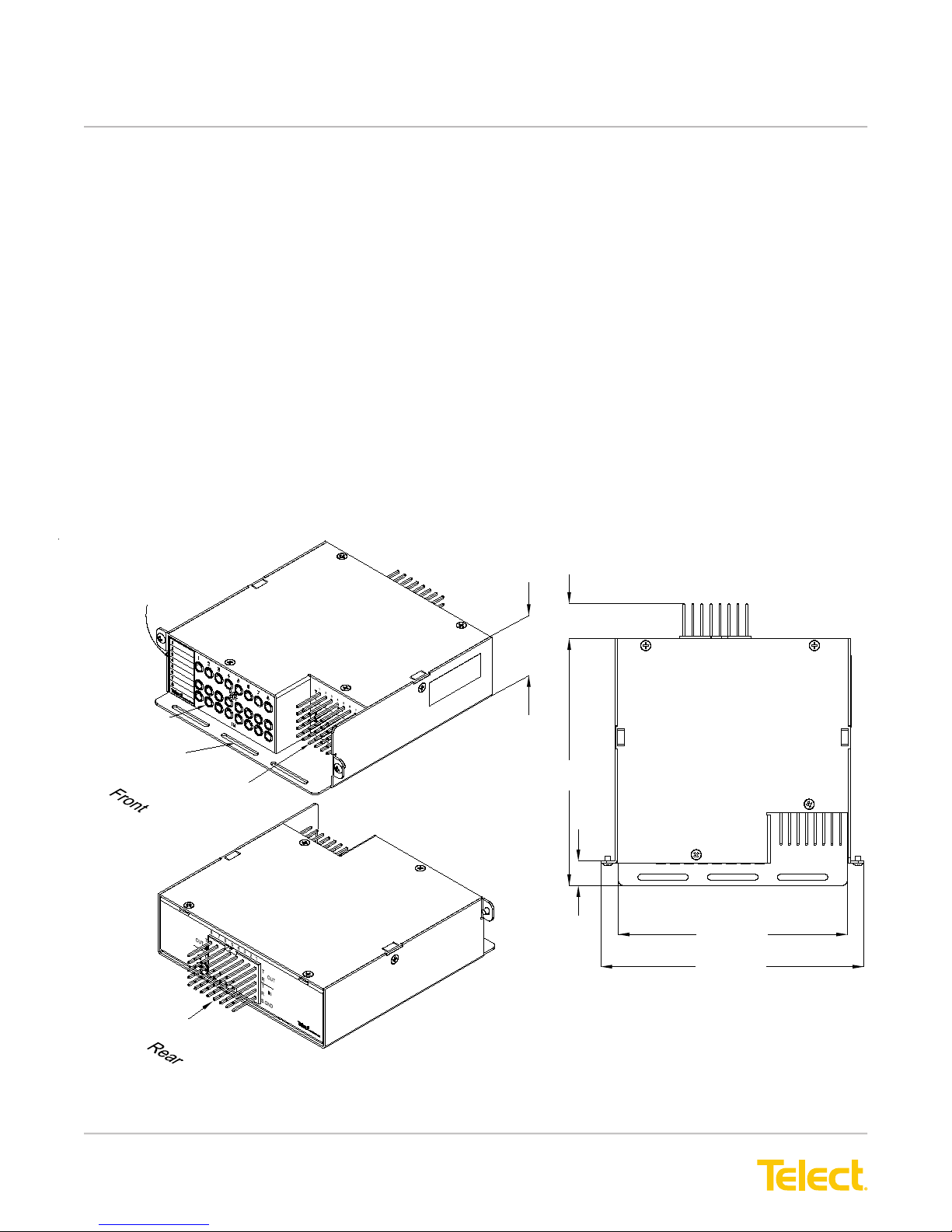
2.1 ELF 8-Termination DSX-1, Wire-Wrap I/O (Model ELF-1008-1100)
Eight-circuit network element I/O wire-wrap pineld on the rear and corresponding cross-connect pineld and
Bantam-style patch and monitor jacks on the front. Both pinelds provide individual shield grounds for each set of
jacks. Screws for mounting module to an ELF chassis or lockable wall-mount enclosure are included.
Circuit Designation
Label
DSX-1 Bantam
Jacks
Jumper
Tie-Down Bar
Cross-Connect Pins
8-Termination Module
1.63
(41.3)
0.78 (19.9)
5.50
(139.7)
0.55
(13.9)
Note: Dimensions are in in. (mm)
Top View
5.11 (129.7)
5.86 (148.8)
Network Element Pinfield
Figure 11 - Model ELF-1008-1100 Dimensions
© Telect, Inc., All Rights Reserved, 124317-10 A0
1.509.926.6000 :: telect.com
17
Page 21
ELF System
Copper / Fiber :: ELF Family
RESISTOR VALUE = 475 ohm
R2
MON
OUT
IN
X-CON
OUT
IN
S. GND.
R1
REFERENCE SCHEMATIC
(TYPICAL FOR ALL CIRCUITS)
T
R
T
R
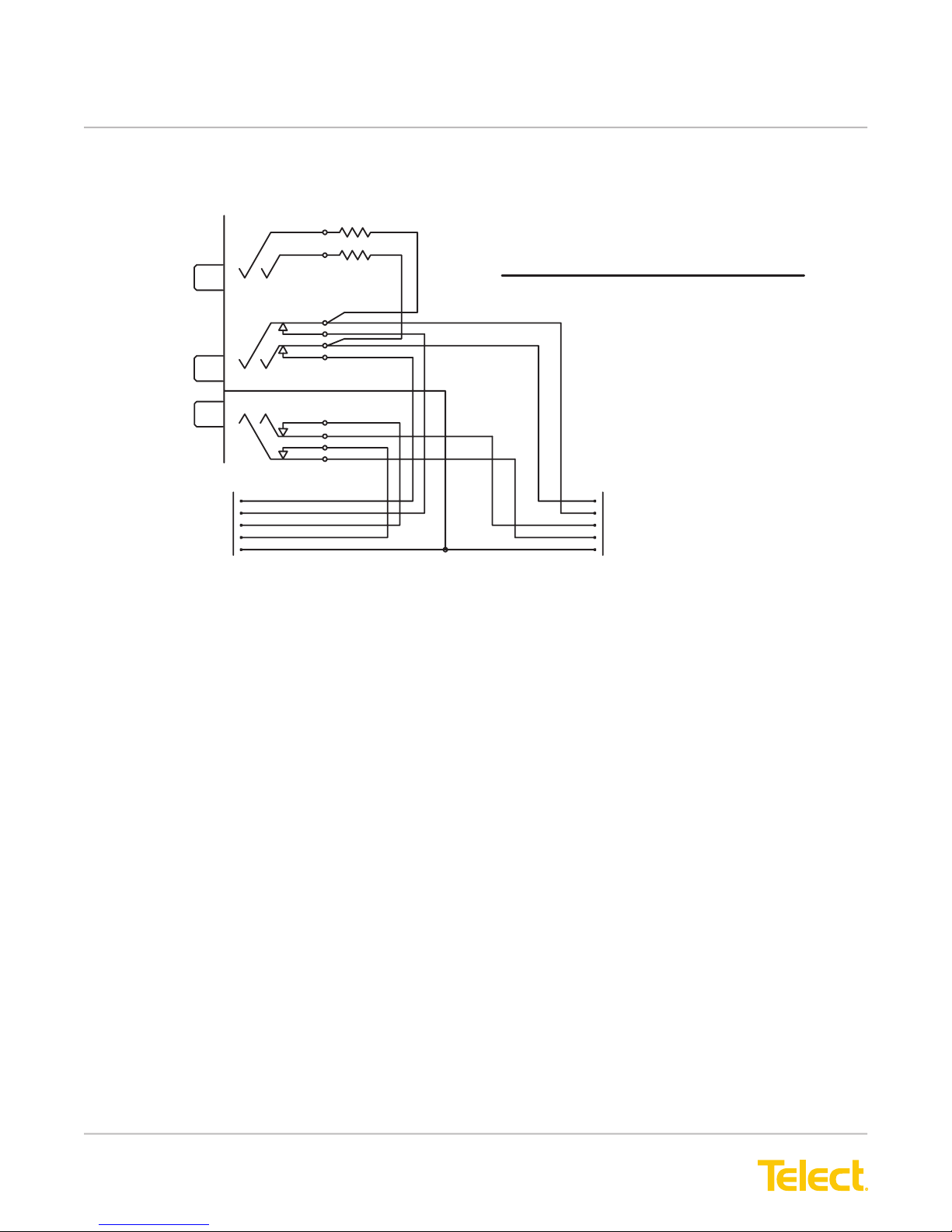
Figure 12 - Model ELF-1008-1100 Reference Schematic
T
OUT
R
T
IN
R
S. GND.
I/O
© Telect, Inc., All Rights Reserved, 124317-10 A0
1.509.926.6000 :: telect.com
18
Page 22
ELF System
Copper / Fiber :: ELF Family
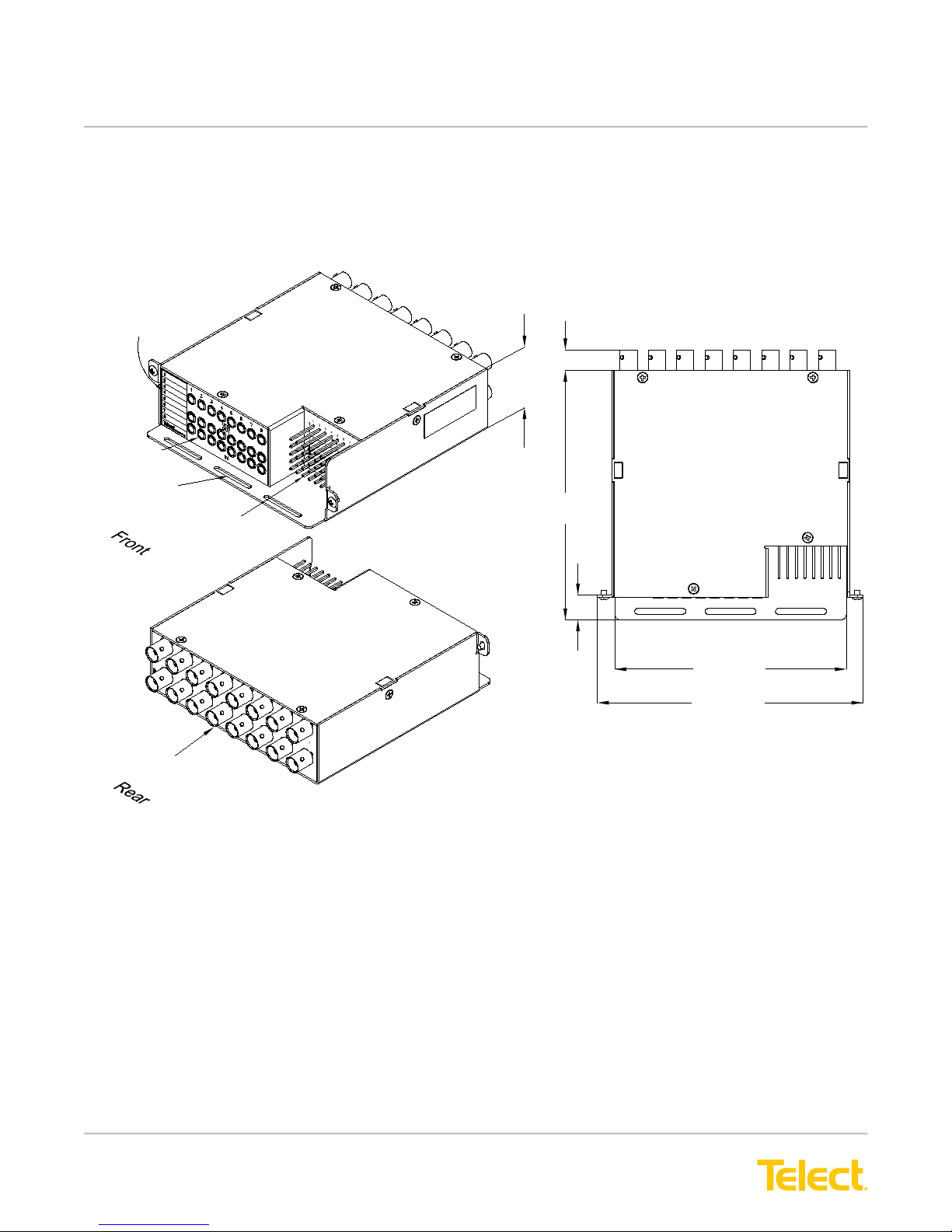
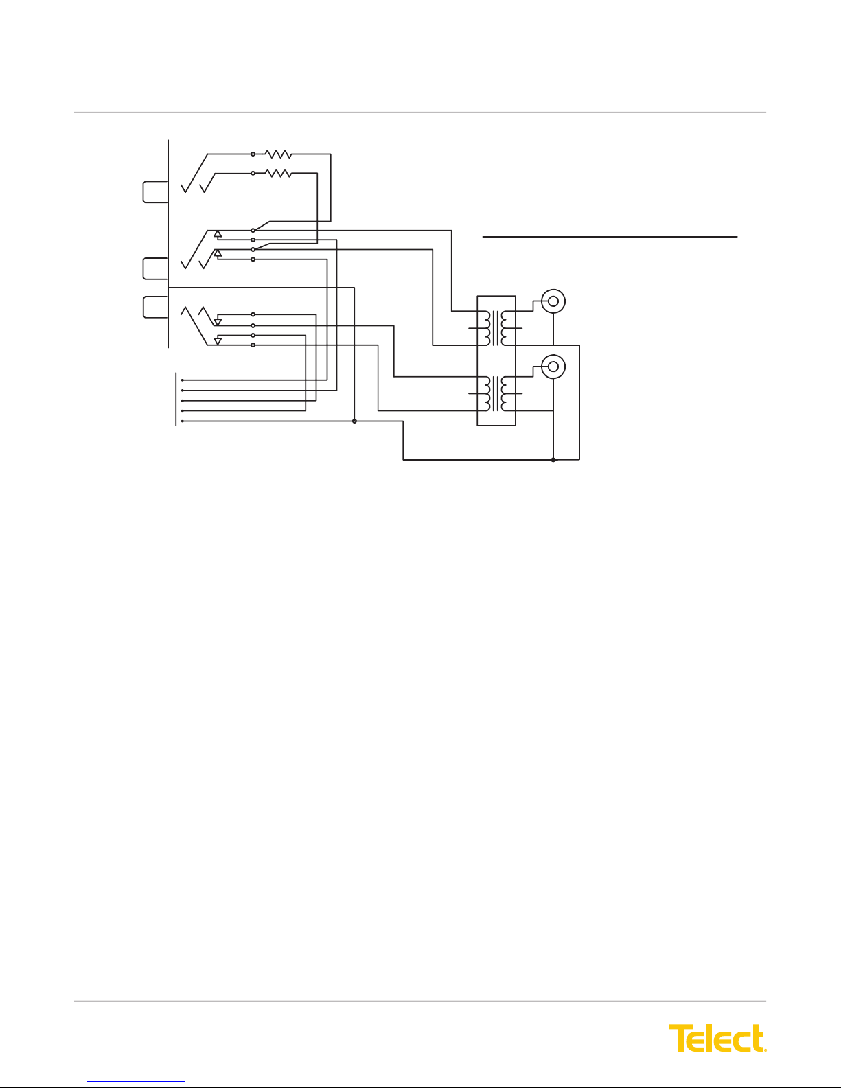
2.2 ELF 8-Termination DSX-1, BNC I/O (Model ELF-1008-1200)
Eight-circuit network element BNCs on the rear and corresponding cross-connect pineld and Bantam-style patch
and monitor jacks on the front. Pineld provides shield grounds for each circuit. Screws for mounting module to an
ELF chassis or lockable wall-mount enclosure are included.
Circuit Designation
Label
DSX-1 Bantam
Jacks
Jumper
Tie-Down Bar
Cross-Connect Pins
8-Termination Module
1.63
(41.3)
0.45 (11.5)
5.50
(139.7)
0.55
(13.9)
Note: Dimensions are in in. (mm)
Top View
5.11 (129.7)
5.86 (148.8)
Network Element BNC Jack Field
Figure 13 - Model ELF-1008-1200 Dimensions
© Telect, Inc., All Rights Reserved, 124317-10 A0
1.509.926.6000 :: telect.com
19
Page 23
ELF System
Copper / Fiber :: ELF Family
R
MON
OUT
IN
R
RESISTOR VALUE = 475 ohm
REFERENCE SCHEMATIC
(TYPICAL FOR ALL CIRCUITS)
T
OUT
I/O
X-CON
OUT
IN
S. GND.
T
R
T
R
75/120 OHM
Figure 14 - Model ELF-1008-1200 Reference Schematic
IN
© Telect, Inc., All Rights Reserved, 124317-10 A0
1.509.926.6000 :: telect.com
20
Page 24
ELF System
Copper / Fiber :: ELF Family
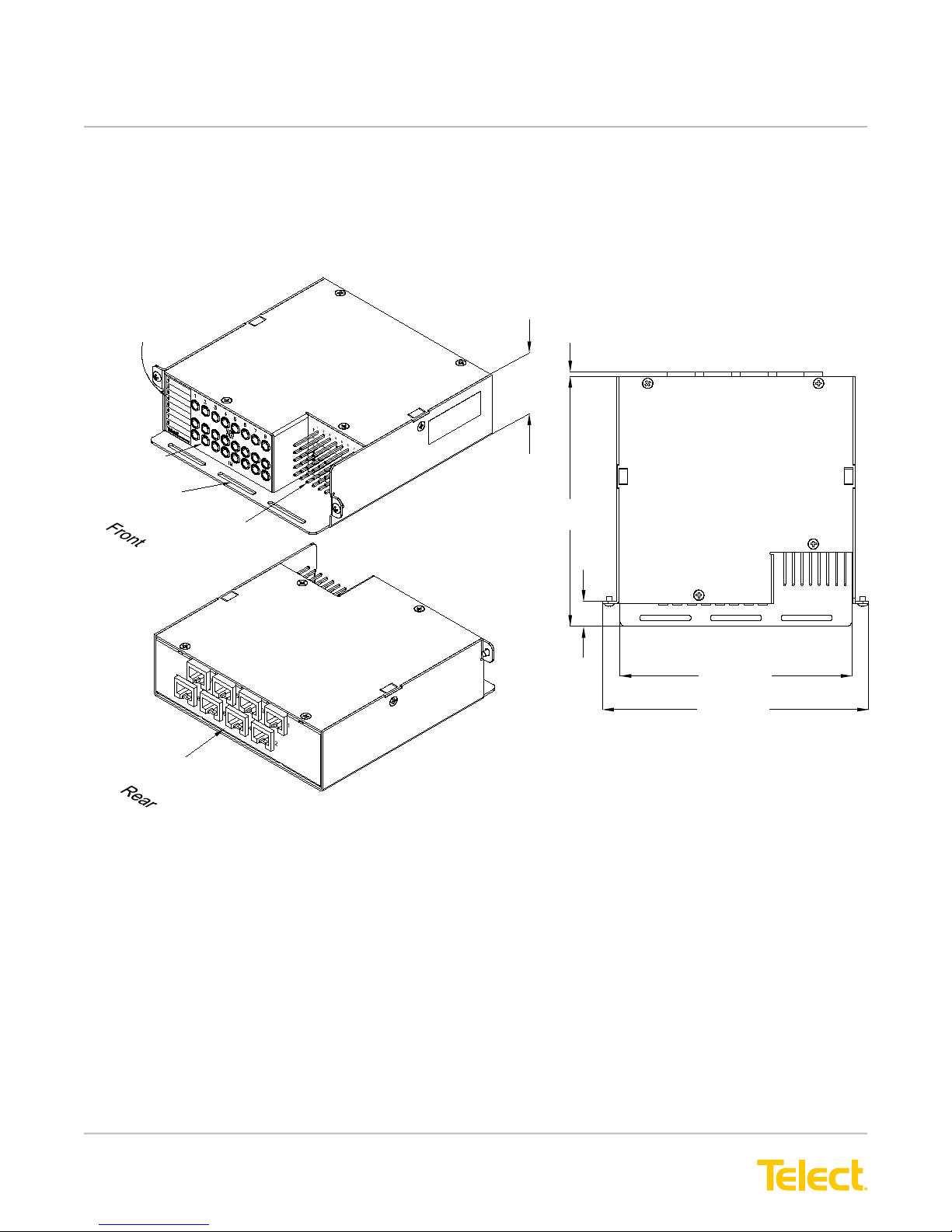
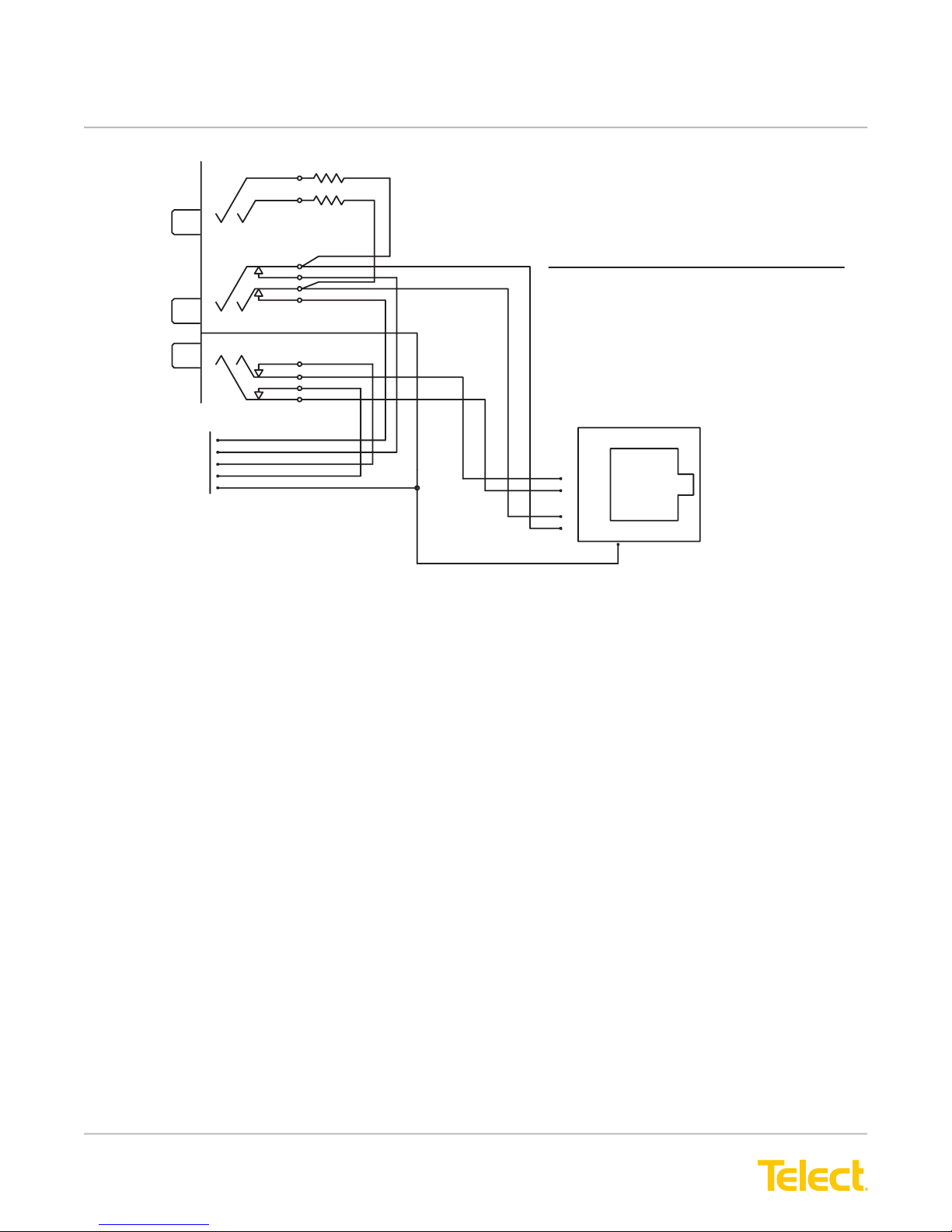
2.3 ELF 8-Termination DSX-1, RJ48C I/O (Model ELF-1008-1800)
Eight-circuit network element RJ48Cs on the rear and corresponding cross-connect pineld and Bantam-style
patch and monitor jacks on the front. Pineld provides shield grounds for each circuit. Screws for mounting
module to an ELF chassis or lockable wall-mount enclosure are included.
Circuit Designation
Label
DSX-1 Bantam
Jacks
Jumper
Tie-Down Bar
Cross-Connect Pins
8-Termination Module
1.63
(41.3)
0.09 (2.4)
5.50
(139.7)
0.55
(13.9)
Note: Dimensions are in in. (mm)
Top View
5.11 (129.7)
5.86 (148.9)
Network Element RJ48C Jack Field
Figure 15 - Model ELF-1008-1800 Dimensions
© Telect, Inc., All Rights Reserved, 124317-10 A0
1.509.926.6000 :: telect.com
21
Page 25
ELF System
Copper / Fiber :: ELF Family
R2
RESISTOR VALUE = 475 ohm
MON
OUT
X-CON
IN
OUT
IN
S. GND.
R1
REFERENCE SCHEMATIC
(TYPICAL FOR ALL CIRCUITS)
I/O
T
R
T
R
OUT
S. GND.
Figure 16 - Model ELF-1008-1800 Reference Schematic
8
7
6
IN
5
T
R
4
3
T
2
1
R
© Telect, Inc., All Rights Reserved, 124317-10 A0
1.509.926.6000 :: telect.com
22
Page 26
ELF System
Copper / Fiber :: ELF Family
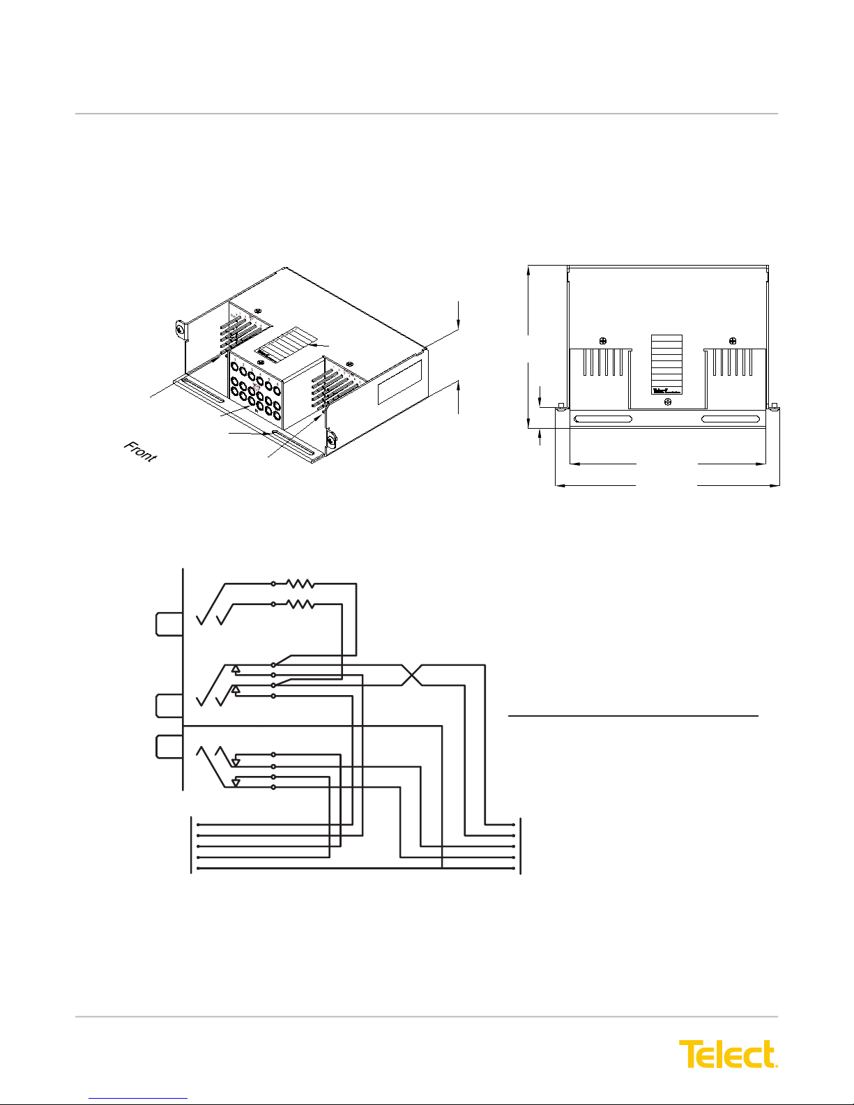
2.4 ELF 6-Termination DSX-1, Wire-Wrap I/O (Model ELF-3006-1100)
Six-circuit NE I/O and cross-connect pinelds and Bantam-style patch and monitor jacks are all on the front. Both
pinelds provide individual shield grounds for each set of jacks. Screws for mounting module to an ELF chassis,
wall-mount bracket, or lockable wall-mount enclosure are included.
6-Termination Module
Network Element Pinfield
DSX-1 Bantam
Jacks
Cross-Connect Pinfield
MON
Jumper
Tie-Down Bar
Note: Dimensions are in in. (mm)
Circuit Designation
Label
1.63
(41.3)
4.25
(108.0)
0.55
(13.9)
Figure 17 - Model ELF-3006-1100 Dimensions
R2
R1
RESISTOR VALUE = 475 ohm
Top View
1
2
3
4
5
6
7
8
5.11 (129.7)
5.86 (148.8)
OUT
IN
T
OUT
R
X-CON
© Telect, Inc., All Rights Reserved, 124317-10 A0
1.509.926.6000 :: telect.com
IN
S. GND.
T
R
Figure 18 - Model ELF-3006-1100 Reference Schematic
23
REFERE NCE SCHEMATIC
(TYPICAL FOR ALL CIRCUITS)
T
OUT
R
T
R
S. GN D.
I/O
IN
Page 27
ELF System
Copper / Fiber :: ELF Family
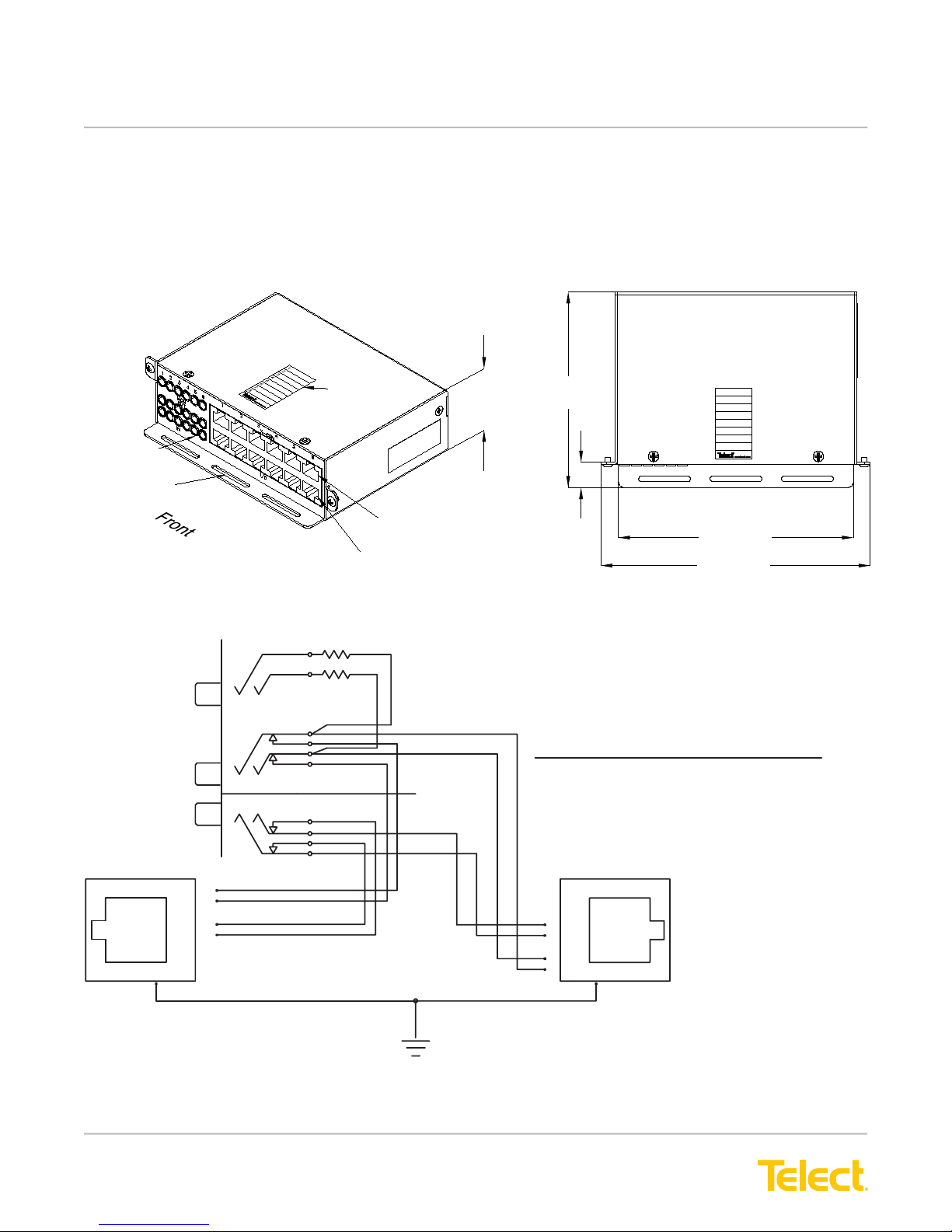
2.5 ELF 6-Termination DSX-1, RJ48C I/O (Model ELF-3006-1800)
Six-circuit network element and cross-connect RJ48Cs, along with Bantam-style patch and monitor jacks, are
all on the front. Screws for mounting module to an ELF chassis, wall-mount bracket, or lockable wall-mount
enclosure are included.
Note: Dimensions are in in. (mm)
6-Termination Module
DSX-1 Bantam
Jacks
Jumper
Tie-Down Bar
MON
OUT
IN
Circuit Designation
Label
Cross-Connect RJ48C Jack Field
Network Element RJ48C Jack Field
1.63
(41.3)
4.25
(108.0)
0.55
(13.9)
Figure 19 - Model ELF-3006-1800 Dimensions
R2
R1
RE SISTOR VALUE = 475 ohm
REFERENCE SCHEMATIC
(TYPICAL FOR ALL CIRCUITS)
Top View
1
2
3
4
5
6
7
8
5.11 (129.7)
5.86 (148.8)
X-CON
OUT
R
1
T
2
3
IN
R
4
T
5
6
7
8
RJ SHIELD GND.
Figure 20 - Model ELF-3006-1800 Reference Schematic
© Telect, Inc., All Rights Reserved, 124317-10 A0
1.509.926.6000 :: telect.com
CHAS SIS GND.
24
OUT
I/O
8
7
6
IN
5
T
R
4
3
T
2
R 1
Page 28
ELF System
Copper / Fiber :: ELF Family
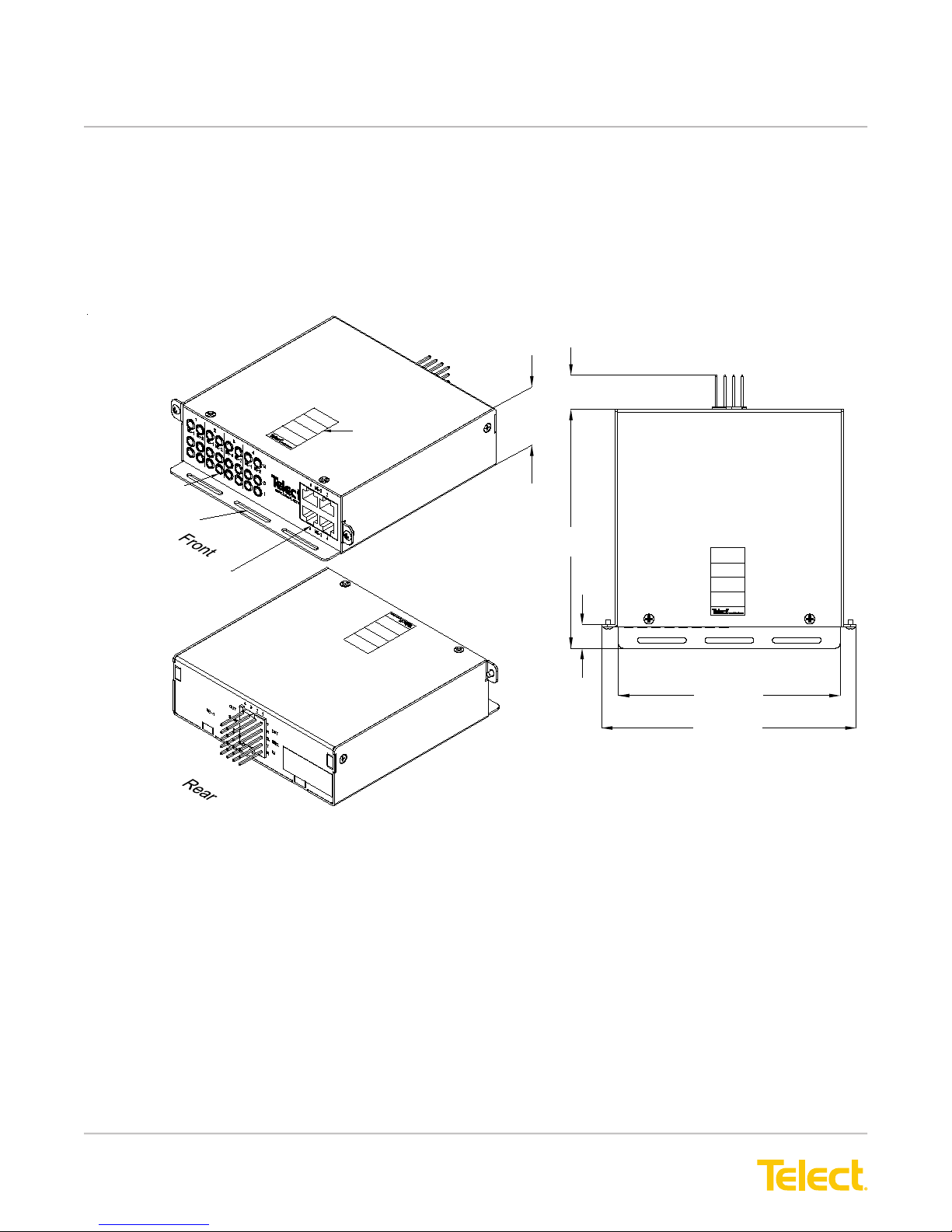
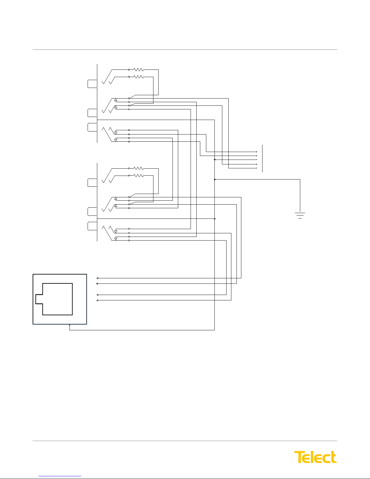
2.6 ELF 4-Circuit DNI-1, Wire-Wrap I/O to RJ48C I/O (Model ELF-9704-1119)
This ELF DNI-1 4-Circuit Module contains 4, NE-1 wire-wrap termination on the rear. 4, NE-2 RJ48C
termination are on the front along with 4 sets of Bantam-style patch and monitor jacks for interconnections and
testing. Shields for all cable connectors are connected internally to chassis ground along with a shield ground
pin for the wire-wrapped NE-1 cable. Screws for mounting module to an ELF chassis or lockable wall-mount
enclosure are included.
DNI-1 Bantam
Jacks
Interconnect Jumper
Tie-Down Bar
NE-2 RJ48C Jack Field
NE-1 Interconnect Pinfield
4-Circuit Interconnect Module
Circuit Designation
Label
1.63
(41.3)
0.78 (19.9)
5.50
(139.7)
0.55
(13.9)
Note: Dimensions are in in. (mm)
Top View
5.11 (129.7)
5.86 (148.8)
Figure 21 - Model ELF-9704-1119 Dimensions
© Telect, Inc., All Rights Reserved, 124317-10 A0
1.509.926.6000 :: telect.com
25
Page 29
ELF System
Copper / Fiber :: ELF Family
R2
NE-1
NE-2
MON
OUT
IN
MON
OUT
IN
R1
R2
R1
RESISTOR VALUE = 475 ohm
T
R
S. GND.
T
R
IN
NE-1
OUT
CHASSIS
GND.
NE-2
OUT
1
R
2
T
3
IN
4
R
T
5
6
7
8
G
Figure 22 - Model ELF-9704-1119 Reference Schematic
© Telect, Inc., All Rights Reserved, 124317-10 A0
1.509.926.6000 :: telect.com
26
Page 30
ELF System
Copper / Fiber :: ELF Family
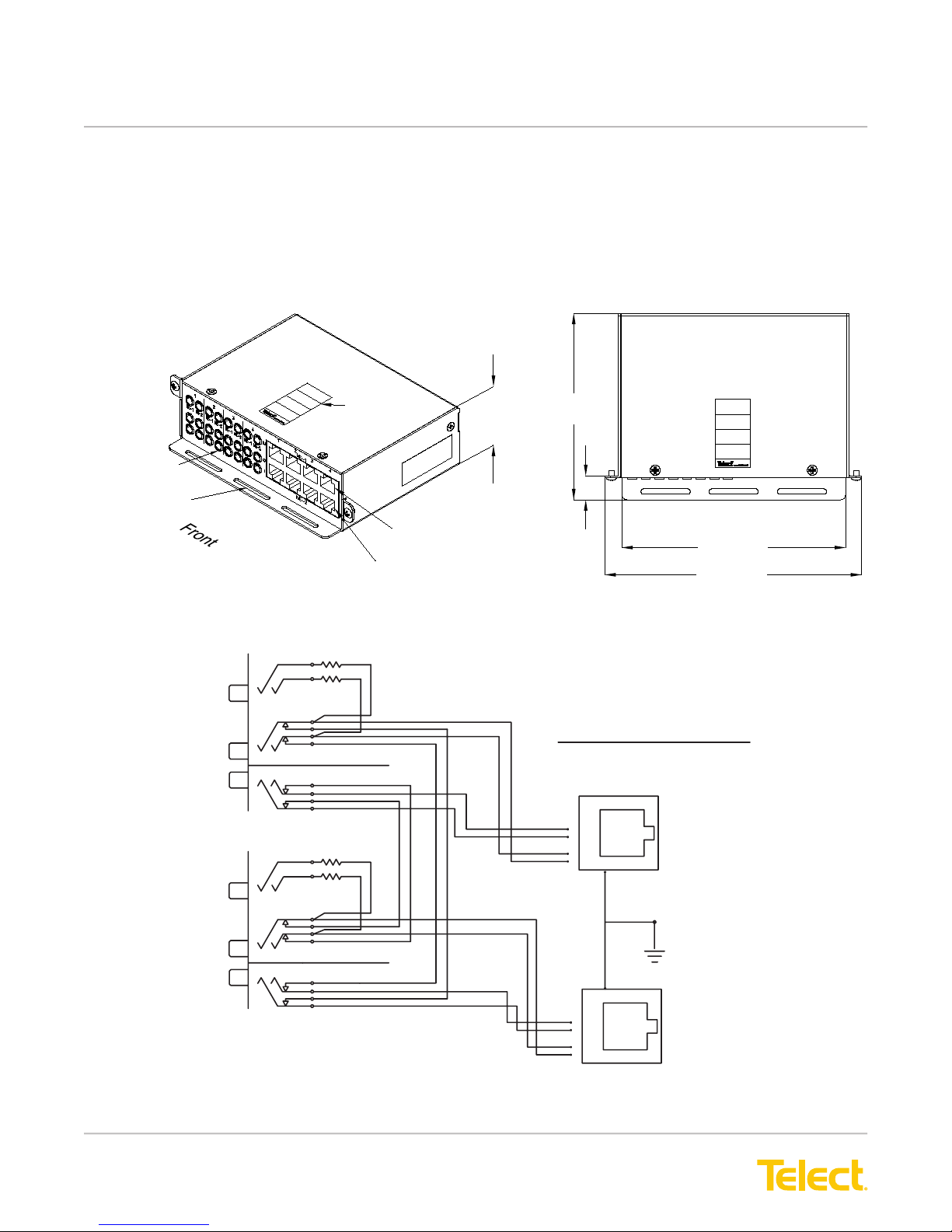
2.7 ELF 4-Circuit DNI-1, RJ48C I/O to RJ48C I/O (Model ELF-3004-1800)
The ELF DNI-1 4-Circuit Total Front Access Module contains 4, NE-1 and 4, NE-2 RJ48C terminations on the front
along with 4 sets of Bantam-style patch and monitor jacks for interconnections and testing. Shields for all cable
connectors are connected internally to chassis ground. Screws for mounting module to an ELF chassis, wall-mount
bracket, or lockable wallmount enclosure are included.
Note: Dimensions are in in. (mm)
DNI-1 Bantam
Jacks
Interconnect Jumper
Tie-Down Bar
4-Circuit Interconnect Module
Circuit Designation
Label
NE-2 RJ48C Jack Field
Figure 23 - Model ELF-3004-1800 Dimensions
R2
MON
OUT
IN
MON
R1
R2
R1
1.63
(41.3)
NE-1 RJ48C Jack Field
RE SIS TOR VALUE = 475 ohm
4.25
(108.0)
0.55
(13.9)
Top View
5.11 (129.7)
5.86 (148.8)
REFERENCE SCHEMATIC
(TYPICAL FOR ALL CIRCUITS)
8
7
6
IN
5
OUT
T
R
T
R
4
3
2
1
RJ SHIELD
GND.
NE-1
OUT
IN
Figure 24 - Model ELF-3004-1800 Reference Schematic
© Telect, Inc., All Rights Reserved, 124317-10 A0
1.509.926.6000 :: telect.com
27
OUT
CHASS IS
GND.
8
7
6
IN
5
T
4
R
3
2
T
1
R
NE-2
Page 31

ELF System
Copper / Fiber :: ELF Family
This page intentionally left blank
© Telect, Inc., All Rights Reserved, 124317-10 A0
1.509.926.6000 :: telect.com
28
Page 32
ELF System
Copper / Fiber :: ELF Family
Chapter 3: ELF DS3 Modules
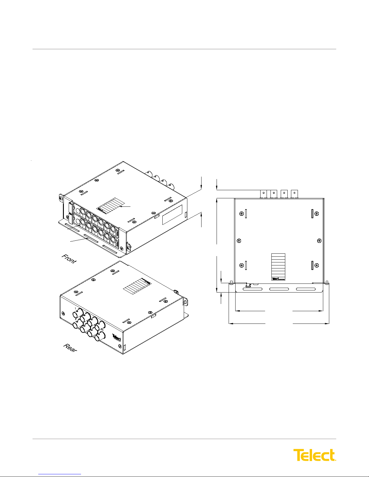
Telect offers two DSX-3 ELF Modules. Both feature 6-port mini-WECOs for temporary I/O and cross-connect
patching, testing, and monitoring, along with BNC connectors for normal NE I/O and cross-connections:
• ELF 2-Termination DSX-3 (Model ELF-3206-1200) has the NE BNCs on the rear, and
• ELF 1-Termination DSX-3 (Model ELF-3206-1900) is total front access (TFA).
Both modules t the ELF chassis and Lockable Wall-Mount Enclosure. Mounting screws for
installing on the chassis or enclosure are included.
3.1 ELF 2-Termination DSX-3, Rear BNC I/O (Model ELF-3206-1200)
Mini-WECO
Jacks
Jumper
Tie-Down Bar
BNC Jacks
2-Termination Module
Circuit Designation
Label
1.63
(41.3)
0.47 (11.9)
5.50
(139.7)
0.55
(13.9)
Note: Dimensions are in in. (mm)
Top View
1
2
3
4
5
6
7
8
5.11 (129.7)
5.86 (148.8)
Figure 25 - Model ELF-3206-1200 Dimensions
© Telect, Inc., All Rights Reserved, 124317-10 A0
1.509.926.6000 :: telect.com
29
Page 33
ELF System
Copper / Fiber :: ELF Family
MON
OX
O
IX
R1=75 OHM 1/4W
R2=768 OHM 1/4W
R 2
OX
R 1
R 1
O
I
R 1
R 1
I
IX
R 2
MON
FRONT
REAR
REFERENCE SCHEMATIC
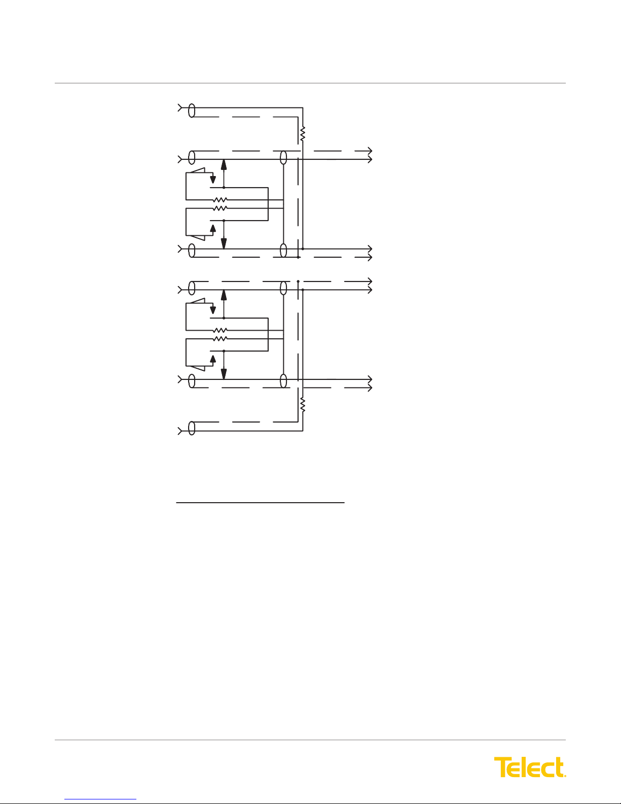
Figure 26 - Model ELF-3206-1200 Reference Schematic
© Telect, Inc., All Rights Reserved, 124317-10 A0
1.509.926.6000 :: telect.com
30
Page 34
ELF System
Copper / Fiber :: ELF Family
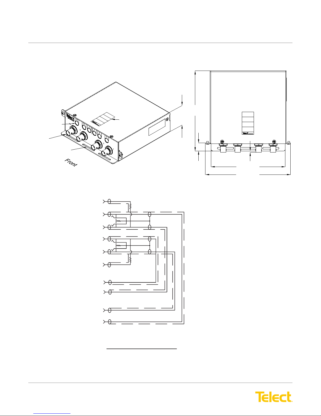
3.2 ELF 1-Termination DSX-3, TFA BNC I/O (Model ELF-3206-1900)
Note: Dimensions are in in. (mm)
Top View
DSX-3 Mini-WECO
Jacks
BNC Jacks
Jumper
Tie-Down Bar
1-Termination Module
Circuit Designation
Label
Figure 27 - Model ELF-3206-1900 Dimensions
MON
OX
O
I
IX
MON
R1
R1
5.50
(139.7)
1.63
(41.3)
0.098 (2.5)
0.55
(13.9)
R2
5.11 (129.7)
5.86 (148.8)
R1=75 OHM 1/4W
R2=768 OHM 1/4W
R2
I
O
IX
OX
FRONT
REFE RENCE SCHEMATIC
Figure 28 - Model ELF-3206-1900 Reference Schematic
© Telect, Inc., All Rights Reserved, 124317-10 A0
1.509.926.6000 :: telect.com
RE AR
31
Page 35

ELF System
Copper / Fiber :: ELF Family
This page intentionally left blank.
© Telect, Inc., All Rights Reserved, 124317-10 A0
1.509.926.6000 :: telect.com
32
Page 36
ELF System
Copper / Fiber :: ELF Family
Chapter 4: ELF Fiber Modules
Telect manufactures two Fiber ELF platforms for patching, and patching with splicing:
• ELF Fiber Patch (Models ELF-PC12-SC00, ELF-PC12-FC00, ELF-PC12-SA00, and ELF-PC24-LC00)
• ELF Fiber Splice/Patch (Models ELF-SP12-SCPT, ELF-SP12-FCPT, and ELF-SP12-SAPT)
All modules are available with either 12, SC/UPC, FC/UPC, SC/APC, or 24 LC/APC adapters. All modules t the
ELF chassis and lockable wall-mount enclosure. Mounting screws for installing on the chassis or enclosure are
included. Telect supplies dust covers for all open ber adapters.
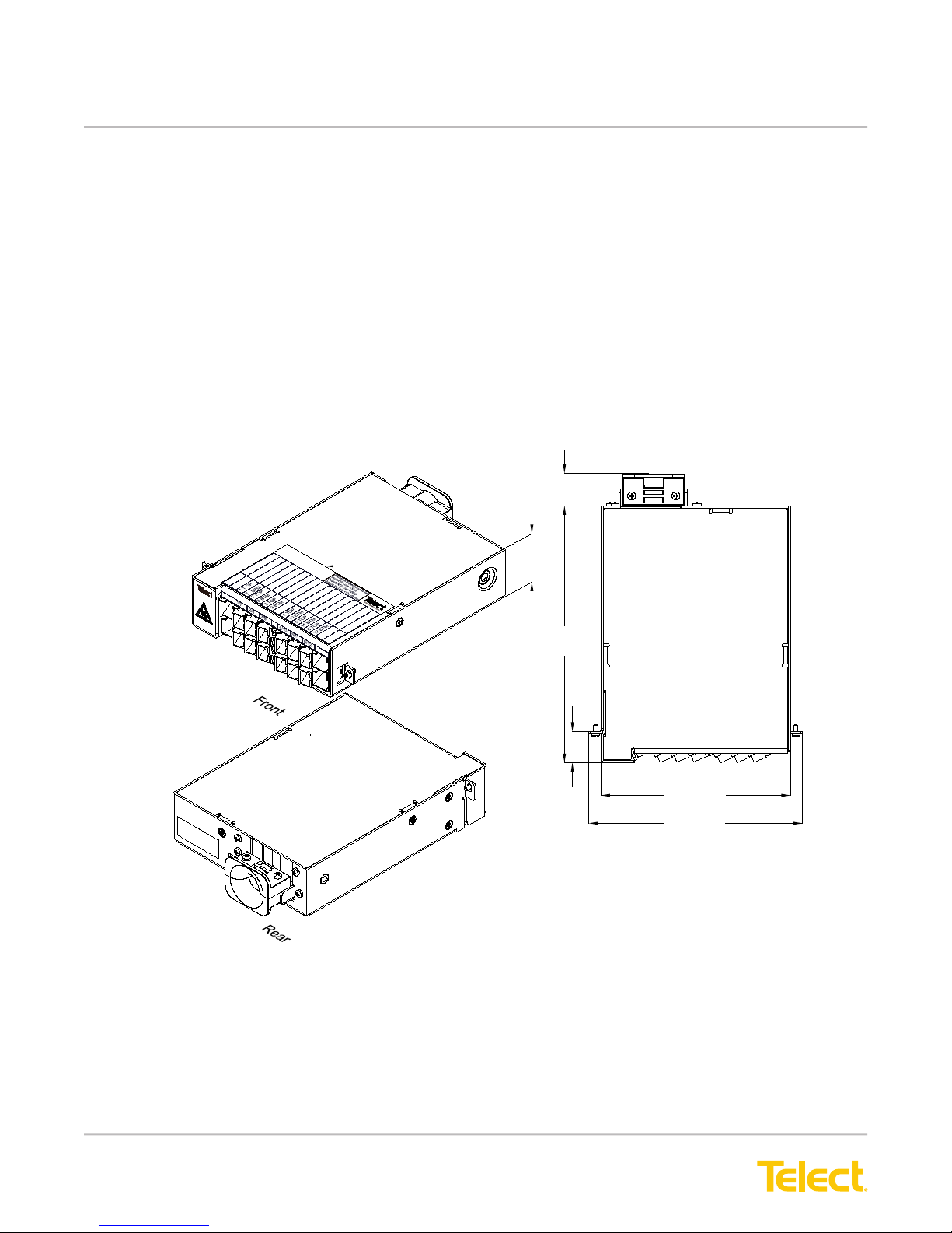
4.1 ELF Fiber Patch Modules (Model Series ELF-PC12-XX00)
The following illustration shows an ELF-PC12-SC00.
Fiber Patch Adapters
Clamshell Guide
for Fiber Jumpers
12-Termination
ELF Fiber Patch Module
Circuit Designation
Label
1.63
(41.3)
0.90 (22.9)
7.21
(183.1)
0.87
(22.0)
Note: Dimensions are in in. (mm)
Top View
5.24 (133.0)
5.90 (150.0)
You can purchase Fiber Patch Modules with factory-installed 2-mm ber jumpers, as shown below
© Telect, Inc., All Rights Reserved, 124317-10 A0
1.509.926.6000 :: telect.com
Figure 29 - ELF-PC12-SC00
33
Page 37
ELF System
Copper / Fiber :: ELF Family
Top Cover
Cable Clamp
Spool
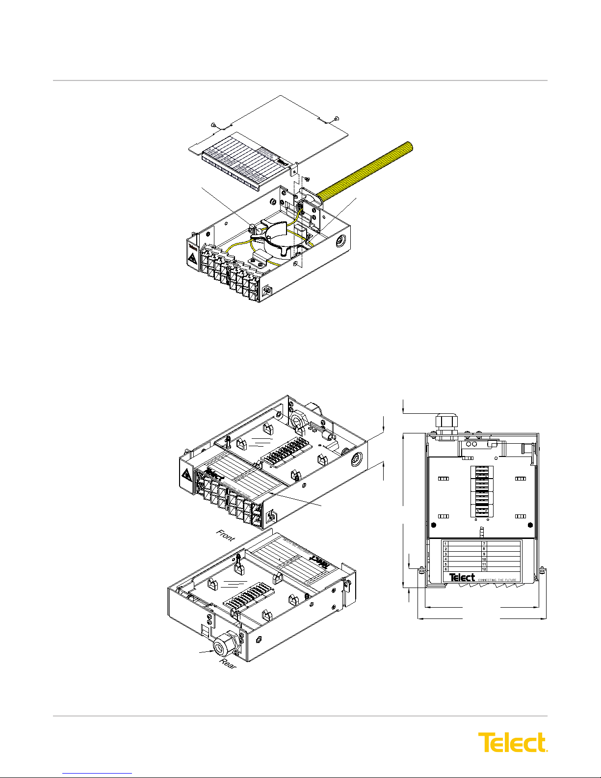
Figure 30 - ELF Patch Module (Model ELF-PC12-SCxx, Typical Cabling
4.2 ELF Fiber Splice/Patch Modules (Model Series ELF-SP12-XXPT)
The following illustration shows an ELF-SP12-XXPT.
1.63
(41.3)
0.90 (22.9)
12-Termination
ELF Fiber Splice/Patch Module
Note: Dimensions are in in. (mm)
Fiber Patch Adapters
Gland-Style Compression Connector
for 12-Strand IFC/OSP Subunit
Figure 31 - Model Series ELF-SP12-XXPT Parts & Dimensions
© Telect, Inc., All Rights Reserved, 124317-10 A0
1.509.926.6000 :: telect.com
34
Circuit Designation
Label
7.21
(183.1)
0.87
(22.0)
5.24 (133.0)
5.90 (148.8)
Top View
Page 38
ELF System
Copper / Fiber :: ELF Family
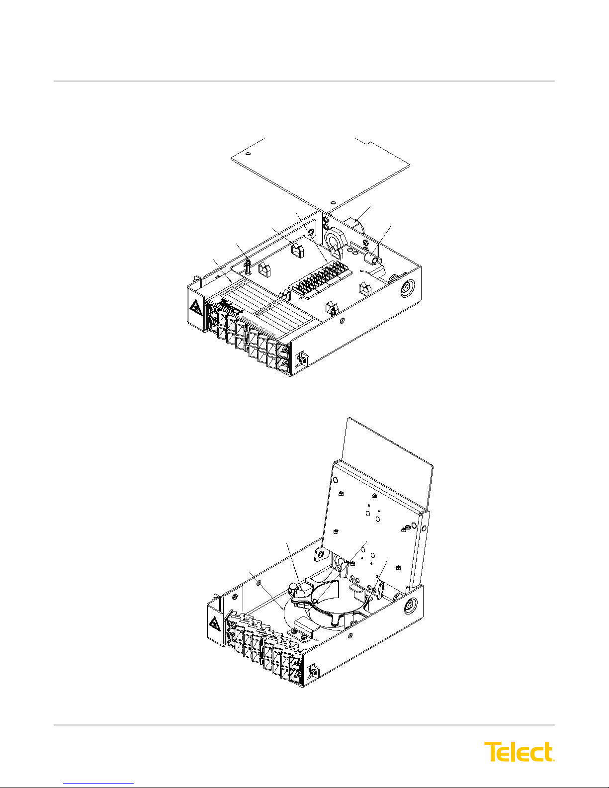
The module consists of a splice cassette mounted atop a subunit entrance compartment. (See the following
illustrations.) The splice cassette is covered by a transparent plastic cover.
Top Cover
Split Stud (2)
Designation Label
Adapters (12)
Splice Holders
Nylon Clips (6)
Splice Deck
Figure 32 - Splice Cassette
Compression Connector
Subunit Clamp
Outer Race for Subunit
Figure 33 - Subunit Entrance Compartment
© Telect, Inc., All Rights Reserved, 124317-10 A0
1.509.926.6000 :: telect.com
Subunit Clamp (2)
Inner Race for Pigtails
Spool
35
Page 39
ELF System
Copper / Fiber :: ELF Family
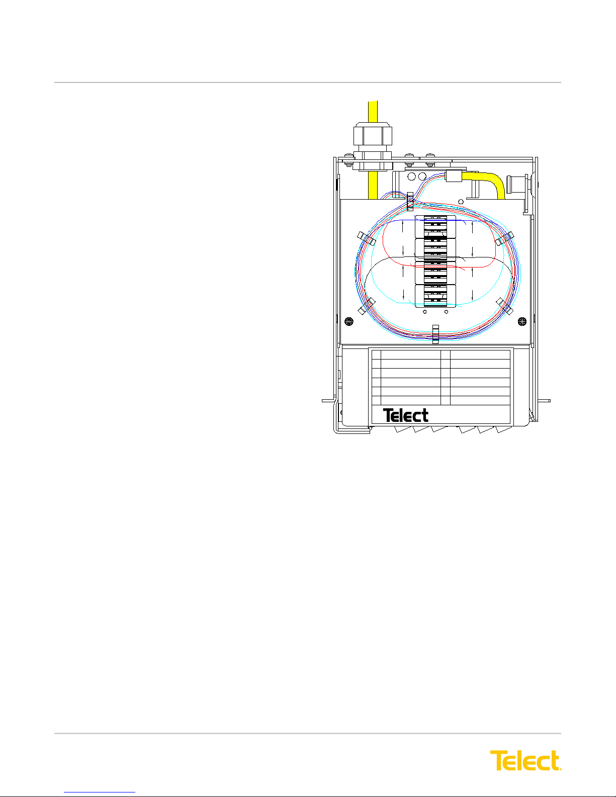
You can purchase Fiber Splice/Patch Modules with 12
factory-installed 900 μm pigtails for splicing to
ber strands from an incoming IFC/OSP subunit.
The opposite ends of factory-installed pigtails are
terminated on the rear face of the ber adapter at
the front of the module.
The illustration on the right shows a nished
installation with 12 ber strands (Model ELF-SP12-SCPT).
1
1
From
Adapters
6
7
From
Subunit
12
1
2
3
4
5
6
From
Subunit
6
7
From
Adapters
12
7
8
9
10
11
12
connec t i ng t he f ut ur e
Figure 34 - ELF Splice/Patch Module
(Model ELF-SP12-SCPT
Typical Cabling)
© Telect, Inc., All Rights Reserved, 124317-10 A0
1.509.926.6000 :: telect.com
36
Page 40

ELF System
Copper / Fiber :: ELF Family
Chapter 5: ELF Multi-Purpose Modules
Telect manufactures three multi-purpose signal manager modules for RJ45C and pin-block signals.
All signal manager modules are straight feed-through:
• The ELF RJ45C to RJ45C Patch Module (Model ELF-9716-1900) contains 16 RJ45C connectors on the rear
which interconnect with 16 RJ45C connectors on the front. The module ts the ELF chassis and lockable
wall-mount enclosure.
• The ELF RJ45 to IDC Patch Module (Model ELF-9716-1700) contains 16 RJ45 connectors on the front which
interconnect to T568A-coded IDC punch-down blocks for 100-Ohm cable on the rear. The module ts the ELF
chassis and lockable wall-mount enclosure.
• The ELF 12 x 4 Alarm Pin Block Module (Model ELF-0005-0001) is a bulkhead pin block primarily intended for
interconnecting alarm signals. ELF-0005-0001 ts the ELF chassis, the wall-mount bracket, and the lockable-
wall-mount enclosure.
Mounting screws for installing on the chassis, bracket, or enclosure are included.
© Telect, Inc., All Rights Reserved, 124317-10 A0
1.509.926.6000 :: telect.com
37
Page 41
ELF System
Copper / Fiber :: ELF Family
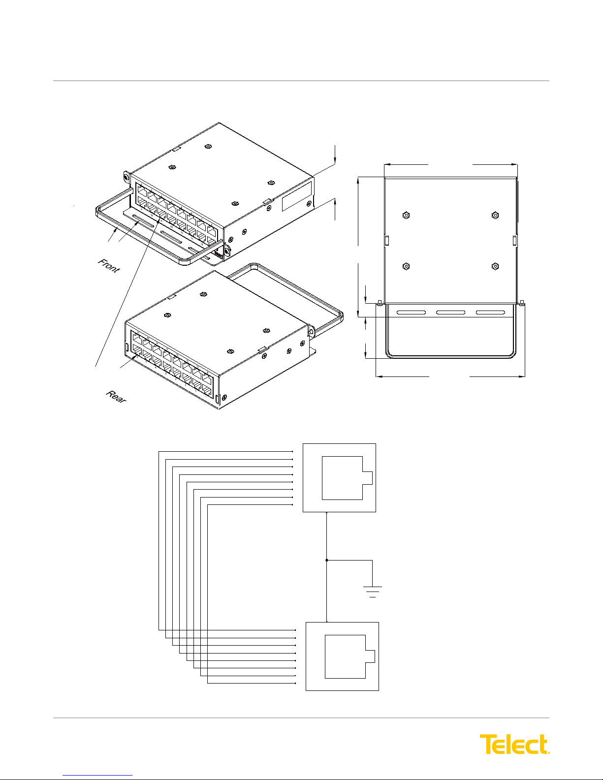
5.1 ELF RJ45C to RJ45C Patch Module (Model ELF-9716-1900)
Note: Dimensions are in in. (mm)
Tie-Down Bars
RJ45C Connectors
16-Termination
RJ45C to RJ45C Patch Module
1.63
(41.3)
5.50
(139.7)
1.62
(41.3)
0.55
(13.9)
Figure 35 - Model ELF-9716-1900 Parts & Dimensions
5.25 (133.4)
Top View
5.86 (148.9)
8
7
6
5
4
3
2
1
RJ SHIELD
GND
CHASSIS
8
7
6
5
4
3
2
1
Figure 36 - Model ELF-9716-1900 Schematic
FRONT
GND
REAR
© Telect, Inc., All Rights Reserved, 124317-10 A0
1.509.926.6000 :: telect.com
38
Page 42
ELF System
Copper / Fiber :: ELF Family
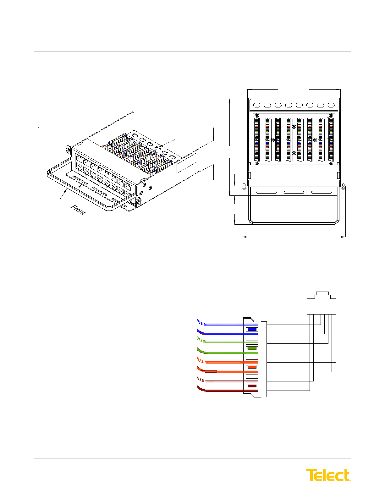
5.2 ELF RJ45-IDC Patch Module (Model ELF-9716-1700)
5.25 (133.4)
16-Termination
Note: Dimensions are in in. (mm)
RJ45-IDC Patch Module
Tie-Down Bar
Tie-Down Bars
Figure 37 - Model ELF-9716-1700 Parts & Dimensions
A schematic illustration is shown on the right and a
nished cable and wiring illustration is shown in the
following illustration.
Please see Telect Publication 129039 for detailed
instructions on installation and wiring.
1.63
(41.3)
WH/BL
BL
WH/GR
GR
WH/OR
OR
WH/BR
BR
5.50
(41.3)
0.55
(13.9)
1.62
9
5
4
3
6
1
2
7
8
5
4
3
6
1
2
7
8
1
IDCs
5
Pair 1
4
3
Pair 2
6
1
Pair 3
2
7
Pair 4
8
10
11
5
5
4
4
3
3
6
6
1
1
2
2
7
7
8
8
5
5
4
4
3
3
6
6
1
1
2
2
7
7
8
8
2
3
5.86 (148.9)
Top View
12
13
5
5
4
4
3
3
6
6
1
1
2
2
7
7
8
8
5
5
4
4
3
3
6
6
1
1
2
2
7
7
8
8
4
5
16
14
5
5
5
5
4
4
4
3
3
3
6
6
6
1
1
1
2
2
2
7
7
7
8
8
8
5
5
5
4
4
4
3
3
3
6
6
6
1
1
1
2
2
2
7
7
7
8
8
8
8
6
7
1
RJ45
8
© Telect, Inc., All Rights Reserved, 124317-10 A0
1.509.926.6000 :: telect.com
1
Figure 38 - Model ELF-9716-1700 Schematic
39
Page 43
ELF System
Copper / Fiber :: ELF Family
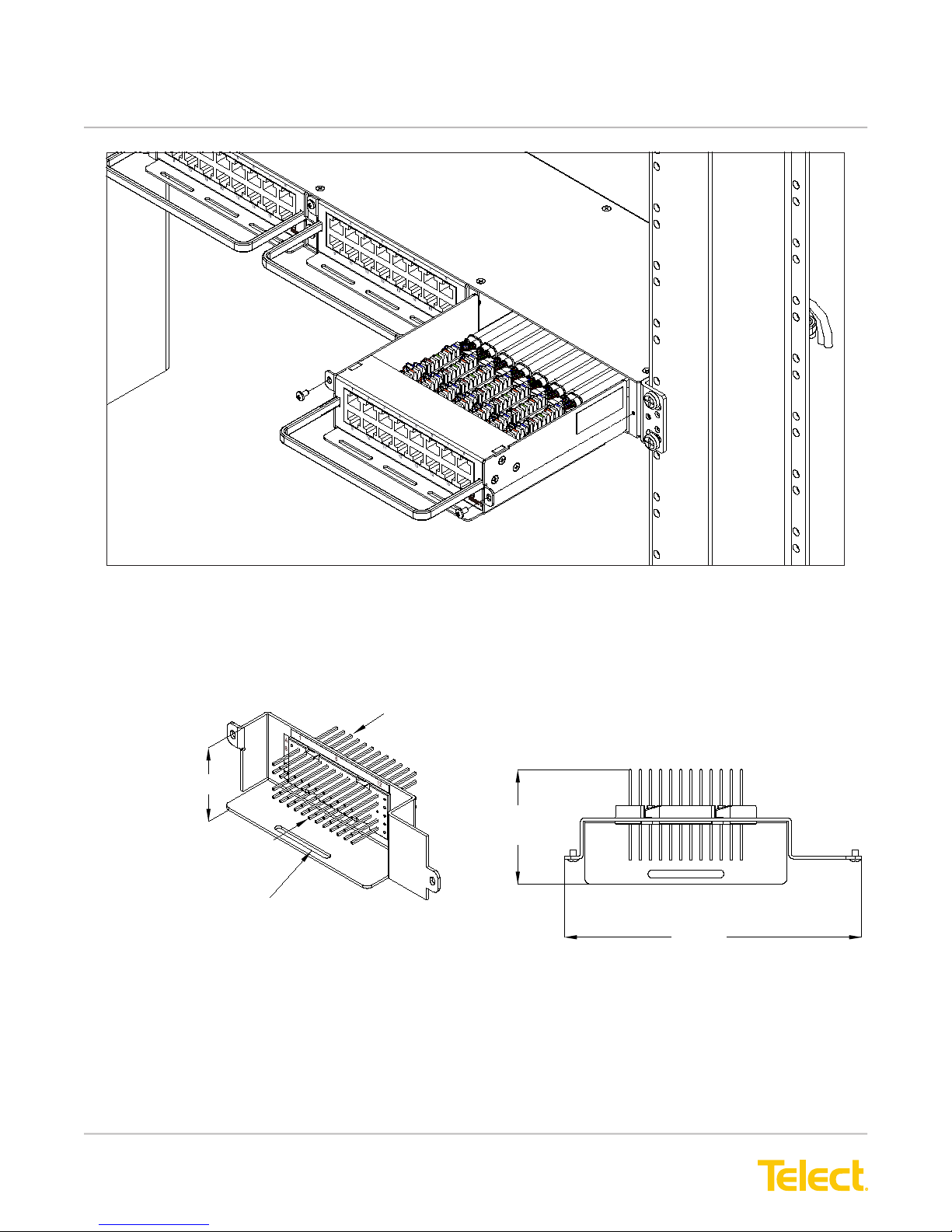
Figure 39 - Example of Model ELF-9716-1700 nished cable and wiring
5.3 ELF 12 x 4 Alarm Pin Block Module (Model ELF-0005-0001)
ELF 12 x 4 Alarm Pin Block
(Model ELF-0005-0001)
1.63 (41.3)
Alarm I/O Cross-Connects
Jumper
Tie-Down
Bar
Figure 40 - Model ELF-0005-0001 Parts & Dimensions
Alarm Interconnects
2.26
(57.4)
5.88
(149.4)
© Telect, Inc., All Rights Reserved, 124317-10 A0
1.509.926.6000 :: telect.com
40
Page 44

ELF System
Copper / Fiber :: ELF Family
Chapter 6: Service
CAUTION
!
CAUTION! Only qualied technicians may install and maintain this product.
6.1 Owner Maintenance
Telect’s ELF chassis, enclosures, and modules do not need preventive maintenance
6.2 Service
Contact Technical Support (USA):
By e-mail: [email protected]
By phone: 888-821-4856 or 509-921-6161
6.2.1 In-Warranty Service
Contact your Telect equipment distributor, or call a Telect Customer Service Representative:
1-509-926-6000
Telect will repair or replace defective products within the limits of the warranty. See “Repacking for Shipment” in
this section.
Call a Customer Service Representative for a Return Material Authorization (RMA) before returning any equipment.
6.2.2 Out-Of-Warranty Service
The procedure for out-of-warranty service is the same as for in-warranty service, except that Telect charges a
processing fee, and you must submit a Purchase Order along with a Return Material Authorization (RMA) before
returning equipment. Call a Customer Service Representative for help getting these forms.
The processing fee guarantees a repair estimate and is credited against actual material and labor costs.
6.3 Repacking For Shipment
1. Tag the equipment showing owner’s name, address, and telephone number, together with a detailed
description of the problem.
2. Use the original shipping container if possible. If you do not have it, package the equipment in a way to
prevent shipping damage. Include the RMA inside the container and legibly print the RMA number on the
outside of the package, near the shipping address
3. Insure the package.
© Telect, Inc., All Rights Reserved, 124317-10 A0
1.509.926.6000 :: telect.com
41
Page 45
ELF System
Copper / Fiber :: ELF Family
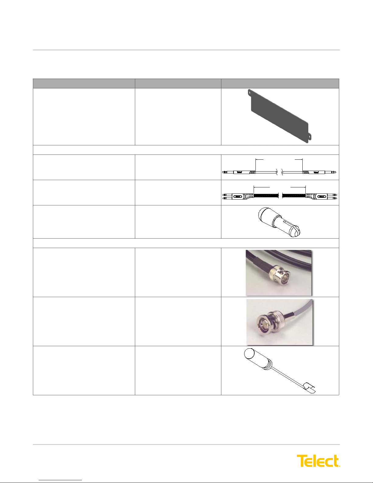
Chapter 7: Accessories
Description Catalog No. Illustration
Blank Face Plate
(Includes Mounting Screws)
Bantam
Bantam Patch Cord,
Single Plug
ELF-0000-0001
040-1000-xxx
where xxx is the length in ft.
XXX FEET
Bantam Patch Cord. Dual Plug 040-2000-xxx
where xxx is the length in ft.
Bantam Circuit Guards
Circuit Guard, BLK
Circuit Guard, RED
BNC
Single RG59
without messenger wire
Single 735A
without messenger wire
BNC Insertion & Removal Tool 097197
101222-2
101222-3
043-0111-xxx where
xxx is length in ft
043-0911-xxx where
xxx is length in ft
XXX FEET
© Telect, Inc., All Rights Reserved, 124317-10 A0
1.509.926.6000 :: telect.com
42
Page 46
ELF System
Copper / Fiber :: ELF Family
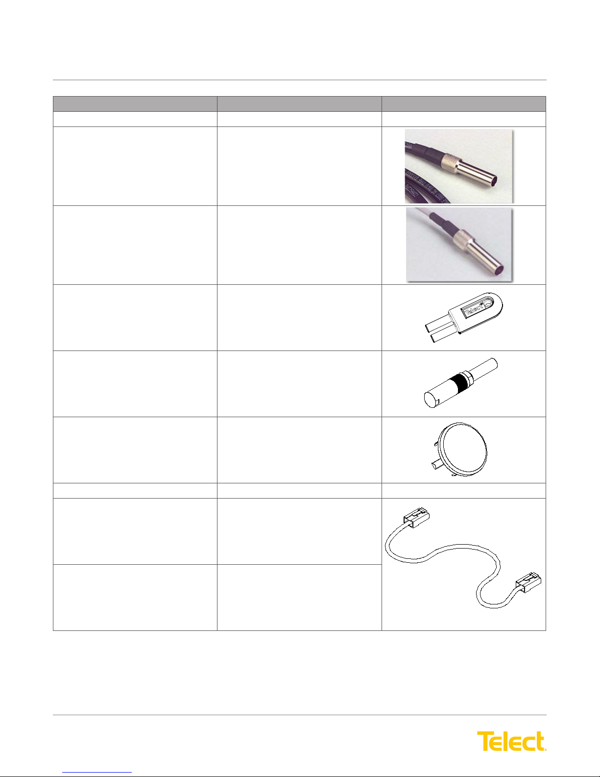
Description Catalog No. Illustration
Mini-WECO
RG59 043-0122-xxx where
xxx is length in ft
735A 043-0922-xxx where
xxx is length in ft
Mini-WECO Looping Plug 301291
Mini-WECO Terminating Plug 100293
Mini-WECO Circuit Guard
Plugs (Black or White)
RJ48C Jumpers
CAT 5ePatch Cords EPCE-CT5E-BLXX where
CAT 6 Patch Cords EPCE-CAT6-BLXX where
PLG-MW-BLK
or PLG-MW-WHT
xx is length in ft
xx is length in ft
© Telect, Inc., All Rights Reserved, 124317-10 A0
1.509.926.6000 :: telect.com
43
Page 47
ELF System
Copper / Fiber :: ELF Family
Description Catalog No. Illustration
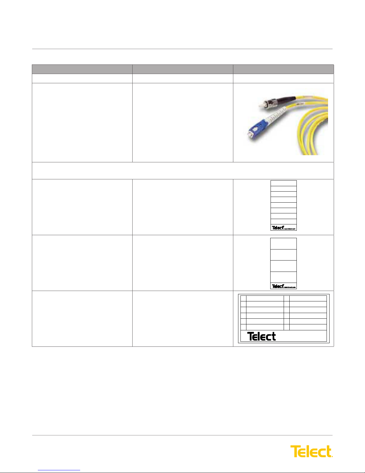
Fiber Jumpers
Single mode or
62.5/125 Multimode
2 mm Simplex SC or
ST Connector on one end;
SC or ST Connector on the
other MegaWave or GigaWave
Any length up to
999.0 ft or 999 m.
Circuit Designations (Self-adhesive circuit designation labels are provided with modules. Order the
labels list here as replacements.)
8 Terminations 123958
See telect.com to access
cable congurator
1
2
3
4
5
6
7
8
1 to 4 Terminations 129396
12 Fiber Terminations 127380
1
2
3
4
5
6
7
8
9
10
11
12
connec t i ng t he f ut ur e
© Telect, Inc., All Rights Reserved, 124317-10 A0
1.509.926.6000 :: telect.com
44
Page 48

ELF System
Copper / Fiber :: ELF Family
This page intentionally left blank.
© Telect, Inc., All Rights Reserved, 124317-10 A0
1.509.926.6000 :: telect.com
45
 Loading...