

Page 1
Advanced Distribution Frame (ADF) Systems
User Manual
Page 2

Advanced Distribution Frame (ADF) Systems
Advanced Distribution Frame (ADF) Systems
User Manual
User Manual
User Manual 119736-4
Copyright 2016, Telect Inc., All Rights Reserved
Telect and Connecting the Future are registered trademarks of Telect, Inc.
22425 East Appleway Ave., # 11
Liberty Lake, WA 99019
Telect assumes no liability from the application or use of these products. Neither does Telect convey any
license under its patent rights nor the patent rights of others. This document and the products described herein
are subject to change without notice.
Connecting the Future for Over 30 Years
Telect challenges the status quo and looks beyond what is possible in network connectivity and
power management.
Founded in 1982, Telect is driven by the principles of innovation and customer service. Headquartered in
Liberty Lake, WA, the privately held company supports a global network of customers with a comprehensive
product portfolio and a values-driven corporate culture.
Our products and solutions are found across communications service-provider networks, data centers and
utility networks around the globe.
At Telect, we pride ourselves on our ability to respond to customer challenges, building a reputation among
communications service providers for delivering solutions uniquely tailored to their needs.
We simplify networks.™
• Exceptional lead-times
• Custom integrated solutions
• Rapid collaborative development and prototyping
• UL and NEBs expertise
Technical Support
E-mail: [email protected]
Phone: 509-926-6000
© Telect, Inc., All Rights Reserved, 12.7.16 v.4
© Telect, Inc., All Rights Reserved, 12.7.16 v.4
1.509.926.6000 :: telect.com
1.509.926.6000 :: telect.com
Page ii
Page 3

Advanced Distribution Frame (ADF) Systems
Advanced Distribution Frame (ADF) Systems
User Manual
User Manual
Table of Contents
Chapter 1: Description ........................................................................................................................... 1
1.1 Overview.......................................................................................................................................... 1
1.1.1 ADF System Features ............................................................................................................... 3
1.2 ADF System Bays............................................................................................................................ 4
1.2.1 ADF XIs ..................................................................................................................................... 7
1.2.2 ADF ICs (after Trough Removed) .............................................................................................. 9
1.3 ADF Modules ..................................................................................................................................11
1.4 Telect ADF Feature Comparison ................................................................................................... 14
1.5 Specications ................................................................................................................................ 16
1.5.1 Weight ..................................................................................................................................... 16
1.5.2 Overall Dimensions ................................................................................................................. 17
Chapter 2: Applications ....................................................................................................................... 19
2.1 Cross-Connect - IFCs to NEs ........................................................................................................ 19
2.2 Cross-Connect - NEs to NEs ......................................................................................................... 20
2.3 Cross-Connect - IFC to IFCs ......................................................................................................... 21
2.4 Interconnect - IFC to IFC ............................................................................................................... 22
2.5 Interconnect - NEs to NEs ............................................................................................................. 23
2.6 Interframe Cross-Connecting ........................................................................................................ 24
2.7 Cross-Connect - IFC to NEs - Working/Protect ............................................................................. 25
2.8 Cross-Connect - IFC to NEs - Working/Protect - Standalone ........................................................ 26
Chapter 3: Frame Installation .............................................................................................................. 27
3.1 Installation Considerations ............................................................................................................ 27
3.1.1 Location & Space .................................................................................................................... 27
3.1.2 Tools & Equipment ................................................................................................................... 27
3.2 Inspection ...................................................................................................................................... 28
3.3 Main & Interbay Storage Panel Installation ................................................................................... 28
3.3.1 Unpacking Main & Interbay Storage Panels ............................................................................ 28
3.3.2 Installing Main & Interbay Storage Panels Directly on a Concrete Floor ................................. 29
3.3.3 Table of Footprint Dimensions ................................................................................................. 31
3.3.4 Installing Lower Trough Junction ............................................................................................. 32
3.3.5 Installing Upper Trough Junction on ADF XI Bays................................................................... 32
3.3.6 Securing ADF to the Lineup..................................................................................................... 33
3.3.7 Installing Rear Cable Tie-Down Bars....................................................................................... 34
© Telect, Inc., All Rights Reserved, 12.7.16 v.4
© Telect, Inc., All Rights Reserved, 12.7.16 v.4
1.509.926.6000 :: telect.com
1.509.926.6000 :: telect.com
Page iii
Page 4

Advanced Distribution Frame (ADF) Systems
Advanced Distribution Frame (ADF) Systems
User Manual
User Manual
3.3.8 Installing Cable Management System (CMS).......................................................................... 36
3.3.9 Grounding ADF ........................................................................................................................ 36
3.3.10 Securing ADF Lineup............................................................................................................. 36
3.3.11 Wiring Facility Power ............................................................................................................. 36
Chapter 4: Module Installation ............................................................................................................ 39
4.1 Installation Considerations ............................................................................................................ 39
4.1.1 Pre-Cabled vs. Uncabled ADF Modules .................................................................................. 39
4.1.2 Tools & Equipment Required ................................................................................................... 39
4.2 Inspection ...................................................................................................................................... 39
4.3 Unpacking an ADF Module ............................................................................................................ 39
4.4 Installing an ADF Module to a Main ADF ....................................................................................... 40
Chapter 5: Outboard Cabling .............................................................................................................. 43
5.1 Intrafacility Cable to Uncabled IFC Module ................................................................................... 43
5.2 Network Cabling to Network Element Module ............................................................................... 47
Chapter 6: Inboard Cabling ................................................................................................................. 51
6.1 Installing Inboard Cabling .............................................................................................................. 51
6.2 Routing & Storing Inboard Cabling ................................................................................................ 54
6.2.1 Interconnection ........................................................................................................................ 54
6.2.2 Cross-Connection .................................................................................................................... 56
Chapter 7: Service ................................................................................................................................ 59
7.1 Owner Maintenance ...................................................................................................................... 59
7.2 Technical Support .......................................................................................................................... 59
7.3 In-Warranty Service ....................................................................................................................... 59
7.4 Out-of-Warranty Service ................................................................................................................ 59
7.5 Repacking for Shipment ................................................................................................................ 59
Chapter 8: Bays and Accessories ....................................................................................................... 61
© Telect, Inc., All Rights Reserved, 12.7.16 v.4
© Telect, Inc., All Rights Reserved, 12.7.16 v.4
1.509.926.6000 :: telect.com
1.509.926.6000 :: telect.com
Page iv
Page 5

Advanced Distribution Frame (ADF) Systems
Advanced Distribution Frame (ADF) Systems
User Manual
User Manual
List of Figures
Figure 1 - Advanced Distribution Frame System ...................................................................................... 1
Figure 2 - Typical Lineup Using ADF Cross-Connect/Interconnect (XI) Bays .......................................... 2
Figure 3 - Main ADF (Typical, Front View with Tray Modules) .................................................................. 4
Figure 4 - Main ADFs (as Shipped, without Tray Modules) ...................................................................... 5
Figure 5 - End Panel................................................................................................................................. 6
Figure 6 - XI Cross-Connect IFC to NE22 ................................................................................................ 7
Figure 7 - Interconnect IFC to NE33......................................................................................................... 8
Figure 8 - Cross-Connect NFC to IE ........................................................................................................ 8
Figure 9 - IFC to NE Interconnection Using ADF ICs in an ADF Lineup................................................... 9
Figure 10 - IFC to NE Interconnection Using ADF ICs in an ADF Lineup (with ISP Storage) ................ 10
Figure 11 - Outboard View of Right-Hand, Intrafacility Cable (IFC) Module ............................................11
Figure 12 - Outboard View of Right-Hand, Network Element (NE) Module ............................................ 12
Figure 13 - Fan-Out Module ................................................................................................................... 12
Figure 14 - Patch Tray (Physically the Same for IFC, NE and FO Modules).......................................... 13
Figure 15 - ADF Comparisons ................................................................................................................ 14
Figure 16 - ADF Comparisons ................................................................................................................ 15
Figure 17 - Cross-Connect - IFC to NEs ................................................................................................ 19
Figure 18 - Cross-Connect - NEs to NEs ............................................................................................... 20
Figure 19 - Cross-Connect - IFC to IFCs................................................................................................ 21
Figure 20 - Interconnect - IFC to IFC...................................................................................................... 22
Figure 21 - Interconnect - NEs to NEs.................................................................................................... 23
Figure 22 - Interframe Cross-Connecting ............................................................................................... 24
Figure 23 - Cross-Connect - IFC to NEs - Working/Project .................................................................... 25
Figure 24 - Cross-Connect - IFC to NEs - Working/Project - Standalone .............................................. 26
Figure 25 - Installation Location ............................................................................................................. 27
Figure 26 - ADF and Interbay Storage Panel Installation Template ........................................................ 29
Figure 27 - ADF and Interbay Storage Panel Footprints ........................................................................ 30
Figure 28 - Lower ADF Junction ............................................................................................................. 32
Figure 29 - Lower Trough Junction Being Secured to the Main ADF XI ................................................. 32
Figure 30 - Rear Corner View of an ADF XI in an ADF Lineup ............................................................... 33
Figure 31 - Rear Corner View of ADF ICs in an ADF Lineup .................................................................. 33
Figure 32 - Recommended Top Feed Conguration .............................................................................. 34
Figure 33 - Recommended Bottom Feed Conguration ......................................................................... 35
Figure 34 - Connect CMS to Main ADF XIs ............................................................................................ 36
Figure 35 - Electrical Raceway (Front of Base) on ADF XI and IC Lineups ........................................... 37
Figure 36 - Installing a Module on a Main ADF ...................................................................................... 41
© Telect, Inc., All Rights Reserved, 12.7.16 v.4
© Telect, Inc., All Rights Reserved, 12.7.16 v.4
1.509.926.6000 :: telect.com
1.509.926.6000 :: telect.com
Page v
Page 6

Advanced Distribution Frame (ADF) Systems
Advanced Distribution Frame (ADF) Systems
User Manual
User Manual
Figure 37 - Adjusting Latch Bars (ADF Module Not Shown) .................................................................. 42
Figure 38 - Intrafacility Clamp and Cable ............................................................................................... 43
Figure 39 - Riser Cabling to Uncabled IFC Module ................................................................................ 44
Figure 40 - Securing Connector to Adapter ............................................................................................ 45
Figure 41 - Routing Cable to Breakout Area........................................................................................... 45
Figure 42 - Excess Cable Routing .......................................................................................................... 46
Figure 43 - Network Element Cabling (Example) ................................................................................... 47
Figure 44 - Opening Trays ...................................................................................................................... 48
Figure 45 - Securing Connector to Adapter ............................................................................................ 48
Figure 46 - Routing Cable to Channel .................................................................................................... 49
Figure 47 - Cable Routing through Channel to Rear of Module ............................................................. 49
Figure 48 - Cable Preparation ................................................................................................................ 51
Figure 49 - Connecting Patch Cord ........................................................................................................ 52
Figure 50 - Cable Routing in Tray........................................................................................................... 52
Figure 51 - Cable Routing in Module ...................................................................................................... 52
Figure 52 - Interconnecting Cable Routing ............................................................................................. 53
Figure 53 - Cross-Connecting Cable Routing......................................................................................... 53
Figure 54 - Cable Routing Down Cascade ............................................................................................. 53
Figure 55 - Interconnection within a Single Frame ................................................................................. 54
Figure 56 - Interconnection with Storage on ISP .................................................................................... 55
Figure 57 - Patching to Same Side of Same ADF .................................................................................. 56
Figure 58 - Patching to Opposite Side of Same ADF ............................................................................. 56
Figure 59 - Patching to Same Side of Different ADFs ............................................................................ 57
Figure 60 - Patching to Opposite Side of Different ADFs (without ISP) .................................................. 57
Figure 61 - Patching to Opposite Side of Different ADFs (with ISP) ....................................................... 58
© Telect, Inc., All Rights Reserved, 12.7.16 v.4
© Telect, Inc., All Rights Reserved, 12.7.16 v.4
1.509.926.6000 :: telect.com
1.509.926.6000 :: telect.com
Page vi
Page 7
Advanced Distribution Frame (ADF) Systems
Chapter 1: Description
Advanced Distribution Frame (ADF) Systems
1.1 Overview
Telect’s ADF Systems provide inter-connectivity and cross-connectivity of intrafacility cables,
network elements, and patch cords.
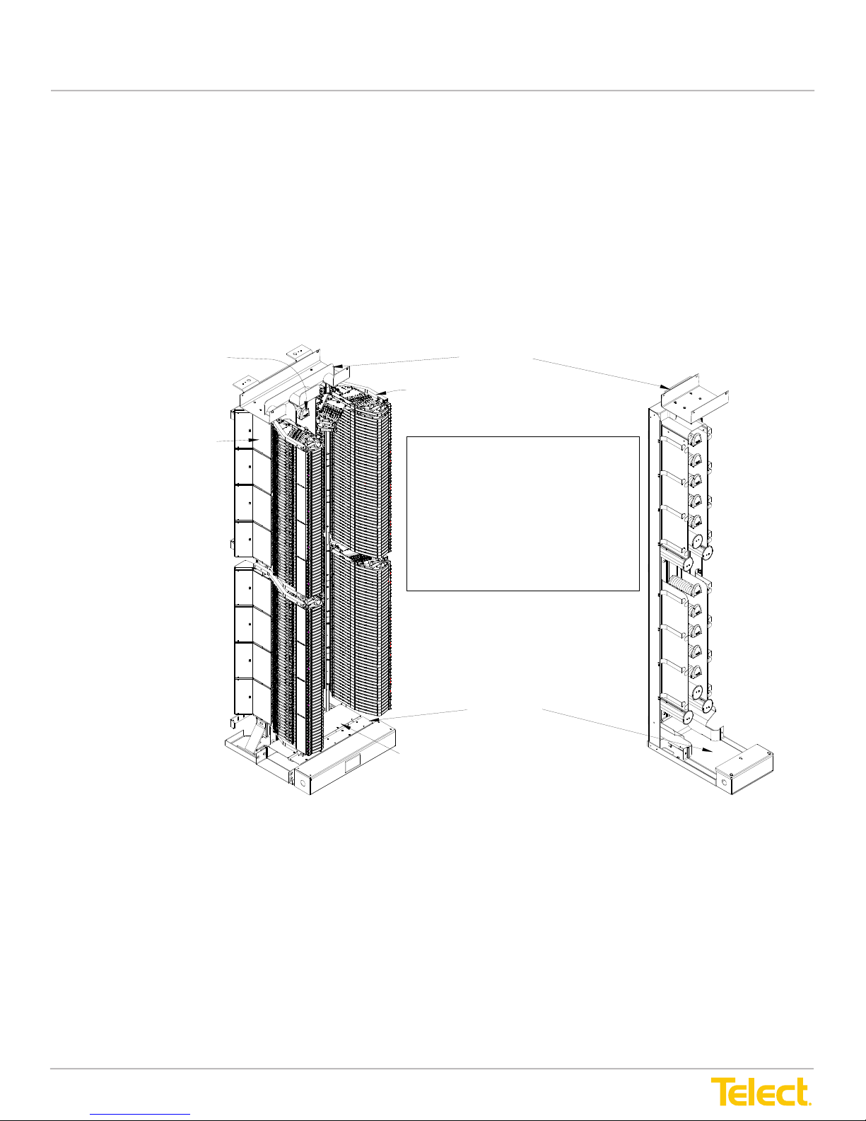
• Each Main ADF consists of an upright frame holding a vertical array of modules on each side
of a patch cord interconnect routing area.
• Each module holds trays for interconnections or cross-connections.
Each swing-out tray supports 6, 8, or 12 optical connections, depending on the type of adapter.
User Manual
Chapter 1: Description
1.1 Overview
The Telect ADF Systems provide inter-connectivity and cross-connectivity of intrafacility cables, network
elements and patch cords.
• Each Main ADF consists of an upright frame holding a vertical array of modules on each side of a patch
cord interconnect routing area
• Each module holds trays for interconnections or cross-connections
Each swing-out tray supports 6,8 or 12 optical connections, depending on the type of adapter.
Vertical Spoo l Array for
R ou tin g P a tch Ca b ling
Between Modules
Trays H old 6, 8, or 12 O ptical Adapters
Upper Trough
Modules With Trays
Covers Protect Cable in Bottom Troughs
ADF Types & Versions
The Telect ADF-XI comes as pictured.
The trough can be removed to provide
inter-connectivity. [ADF-IC]
Two versions of ADF XI are offered,
an ETSI versions and a North American
version. The ETSI version is shown here.
Lower Trough
ADF-26F-XI ADF-12INT-XI
Figure 1 - Advanced Distribution Frame System
• ADFs with 12 adapters per tray have up to 2304 junctions per bay (LC)
• ADFs with 8 adapters per tray have up to 1536 junctions per bay
• ADFs with 6 adapters per tray have up to 1152 junctions per bay
© Telect, Inc., All Rights Reserved, 12.7.16 v.4
1.509.926.6000 :: telect.com
1
Page 8

Advanced Distribution Frame (ADF) Systems
Figure 1, “Advanced Distribution Frame System” on page 1, depicts a multipurpose ADF XI bay
with a complete array of modules and an ADF InterBay Storage panel.
The area between right-side and left-side modules contains various spools for routing patch
cords and/or pigtail interconnects. Bulk patch cord storage is provided by InterBay Storage
Panels (ISPs) located between Main ADFs in ADF System lineups.
User Manual
Figure 1, “Advanced Distribution Frame System” on page 1, depicts a multi-purpose ADF XI bay with a
complete array of modules and an ADF InterBay Storage Panel.
The area between right-side and left-side modules contains various spools for routing patch cords and/or pigtail interconnects. Bulk patch cord storage is provided by Interbay Storage Panels (ISPs) located between Main
ADFs in ADF System lineups.
Normally, the top tray of ea ch
qua drant is covered to protect cab les
and ad apters from overhead hazards.
Bottom-Up IFC Cabling (IFC can be routed from the top-down
or bottom-up on all Main ADFs)
Rear View of Main ADF Showing IFC
Front View
Cable at Rear of ADF Module
Figure 2 - Typical Lineup Using ADF Cross-Connect/Interconnect (XI) Bays
ADF system lineups consist of Main ADF, ISPs and end panels.
Cable, patch cord and pigtail access differs somewhat between the Telect ADF Cross-Connect/Interconnect
(XI) and Interconnect (IC) Systems, but generally IFC, OSP or network element
© Telect, Inc., All Rights Reserved, 12.7.16 v.4
1.509.926.6000 :: telect.com
2
Page 9

Advanced Distribution Frame (ADF) Systems
User Manual
(NE) access are connected at the rear of the modules. Patch cords, as well as NE pigtail interconnects, are
connected at the front of the modules. In cross-connect applications, patch cords are routed between modules
on different Main ADFs through upper and/or lower ADF troughs.
1.1.1 ADF System Features
• Industry-leading termination density
• Simple, straight-forward cable management, access, circuit identication and isolation
• No shing of cables
• Total front access for patching
• Designed for compliance (ber bend radius control, ammability safety, structural reliability) throughout
ADF design
• No line-of-sight laser hazards
• Easy access to riser/network/patch cord interconnections and cross-connections
• Light-weight, heavy-duty frame certied for Zone 4 earthquake reliability
• Easy installation
• 600-mm and 26-in. rack widths that accommodate standard lineups
• Diverse routing with reduced cable congestion, diverse routing between ADFs using upper and/or
lower troughs
• 4.5 m standard, single-length patch cords for ADF cross connections
• Unique storage spools with wave-like ridges for grouping patch cords
• Variable placement of tray modules on ADF mounting rails
• Compatible with WaveTrax™ Cable Management System and other cable management systems
© Telect, Inc., All Rights Reserved, 12.7.16 v.4
1.509.926.6000 :: telect.com
3
Page 10
Advanced Distribution Frame (ADF) Systems
1.2 ADF System Bays
As mentioned, ADF Systems consist of Main ADFs with modules, InterBay Storage Panels
(ISPs), and end panels.
User Manual
1.2 ADF System Bays
As mentioned, ADF Systems consist of Main ADFs with modules, Interbay Storage Panels (ISPs)
and End Panels.
Intrafacility Cabling
Figure 3 - Main ADF (Typical, Front View with Tray Modules)
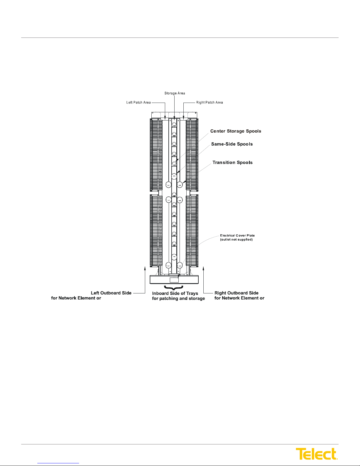
Main ADFs, such as the Main ADF XI in Figure 3, above, consist of a central cable storage area with mounting
rails for the ber tray modules. The routing area contains several types of spools for directing and redirecting
patch cords and pigtail interconnects.
Interconnect and cross-connect cabling differs somewhat between the Main ADF XI and IC bays:
• Main ADF XI - Interconnection and cross-connection cabling to the inboard patch areas is provided by
either upper and/or lower cable troughs. Drops in the troughs ensure cable bend radius control. Junctions
are provided for coupling the upper and lower troughs to other Main ADFs or Interbay Storage Panels in
the lineup.
Intrafacility Cabling
• Main ADF IC (Specialized for Interconnections) - Interconnect cabling to the inboard patch area is by direct
access from a cable management system above the ADF lineup. Junctions are provided for coupling the
lower troughs of all Main and Interbay Storage Panels in the lineup.
© Telect, Inc., All Rights Reserved, 12.7.16 v.4
1.509.926.6000 :: telect.com
4
Page 11
Advanced Distribution Frame (ADF) Systems
are provided for coupling the lower troughs of all Main and InterBay Storage Panels
in the lineup.
At the bottom is an electrical raceway for power cabling and conduit. The raceway provides a
mounting area for a standard recessed receptacle or other wiring device.
Small holes are tappedto connect dual-hole grounding
Main ADF XI only
User Manual
At the bottom is an electrical raceway for power cabling and conduit. The raceway provides a mounting area
for a standard recessed receptacle or other wiring device.
lug usin g M5 scr ews
Main ADF Interconnect (IC)
(shown with top trough removed)
Junction (not shown) fits on the edge to
connect the upper trough to the adjacent
frame in the lineup (Main ADF XI [cross-connect] only)
Main ADF IC
(shown without top trough)
Lar g e hole s f or s ecur i ng ADF
to th e CMS or a la dder ra ck
Upper ADF Trough (Main ADF XI Only)
Catch for Tray Latch
Lower ADF Trough
Patch Cord Cascade
With Turn stiles
Coupling (not shown) fits on lip to
connect lower troughto adjacent
frame in lineup
Cover Plate for Standard Electrical
Receptacle
31.8 mm/1.25 in. (Diameter) AccessHole
on Both Ends of Raceway
Main ADF XI
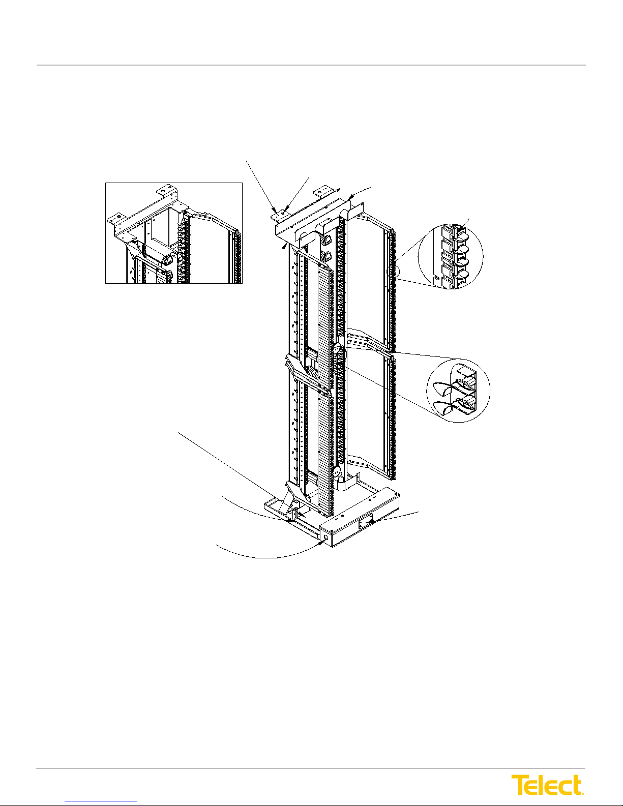
Figure 4 - Main ADFs (as Shipped, without Tray Modules)
An Interbay Storage Panel (ISP) is used for storage of either patch cord cabling from an overhead CMS and/or
inboard cabling terminated at IFC or NE modules. Except for the tray modules, cable routing through an
Interbay Storage Panel is similar to that of a Main ADF.
The Main ADF and ISP can be mounted directly to a concrete oor or on a raised equipment oor. (A template
is provided for mounting panels to the oor.) Support is provided at the top for added earthquake security and
for attaching to a cable management or ladder rack system.
© Telect, Inc., All Rights Reserved, 12.7.16 v.4
1.509.926.6000 :: telect.com
5
Page 12
Advanced Distribution Frame (ADF) Systems
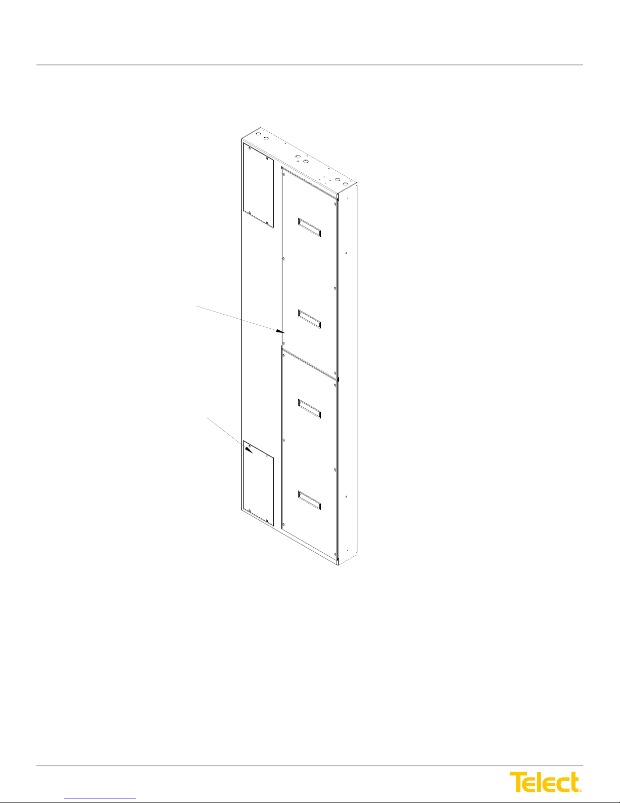
Normally, ADF lineups are terminated at each end by ADF End Panels secured to adjacent ISPs.
User Manual
Normally, ADF lineups are terminated at each end by ADF End Panels secured to adjacent ISPs.
Doors (2)
Access Covers (2)
Figure 5 - End Panel
You can congure two types of ADF System bays that t North American and ETSI footprints:
1. ADF Cross-Connect/Interconnect (XI) Bays
2. ADF Interconnect (IC) Bays
The subsections that follow describe and illustrate various cabling scenarios provided by each of these types
of ADF systems. Chaper 2, “Applications” on page 19, provides comprehensive and comparative analyses of
cabling using these two systems.
© Telect, Inc., All Rights Reserved, 12.7.16 v.4
1.509.926.6000 :: telect.com
6
Page 13
Advanced Distribution Frame (ADF) Systems
1.2.1 ADF XIs
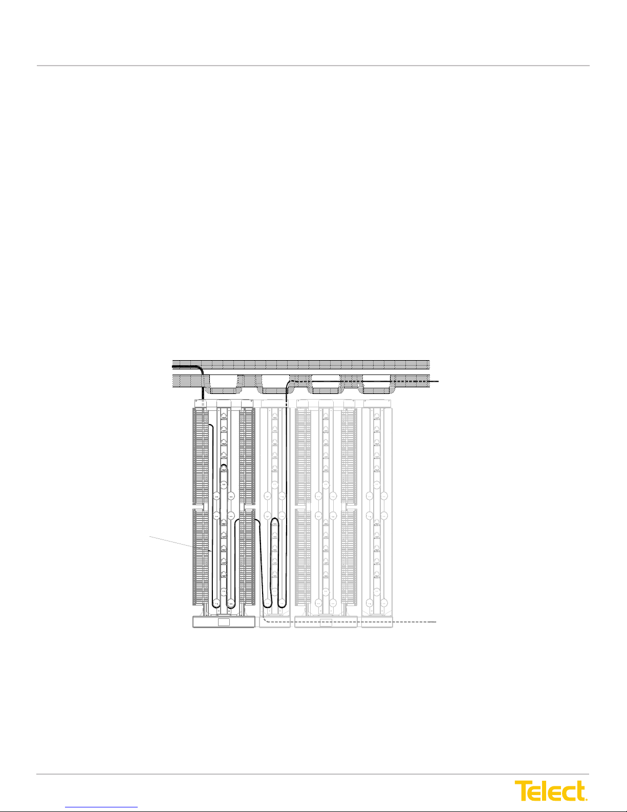
ADF Cross-Connect/Interconnect bays are used in either cross-connect or interconnect
applications, depending on the type of module installed on the Main ADFs. Lineup access to the
patch cord area on the Main ADFs is through either the bottom or upper troughs with access to/
from patch cord storage on the ISPs via the bottom trough.
Two models are available:
1. The North American model is based on a 26 in. by 24 in. Main ADF footprint. ISPs for the
North
American model are 12 in. by 24 in.
2. The ETSI model is based on a 600 mm by 600 mm Main ADF footprint. ISPs for the ETSI
model are 30
0 mm by 600 mm.
The following figures show a few typical cross-
connection and interconnection schemes between
IFC and network element (NE) cabling. In these examples, IFC routing to the rear of the IFC ADF
modules is from the facilities cable (ladder) rack with NE cabling through a cable management
system (CMS).
Ladder Rack
User Manual
1.2.1 ADF XIs
ADF Cross-Connect/Interconnect bays are used in either cross-connect or interconnect applications,
depending on the type of module installed on the Main ADFs. Lineup access to the patch cord area on the
Main ADFs is through either the bottom or upper troughs with access to/from patch cord storage on the ISPs
via the bottom trough.
Two models are available:
1. The North American model is based on a 26" by 24" Main ADF footprint. ISPs for the North American model
are 12" by 24".
2. The ETSI model is based on a 600 mm by 600 mm Main ADF footprint. ISPs for the ETSI model are 300
mm by 600 mm.
The following gures show a few typical cross-connection and interconnection schemes between IFC and
network element (NE) cabling. In these examples, IFC routing to the rear of the IFC ADF modules is from the
facilities cable (ladder) rack with NE cabling through a cable management system (CMS).
IFC Cabling to Rear
(Outboard Side)
of IFC Module
CMS
Preferred Pigtail
Route from Outboard
Side of NE Module
Via CMS to Network
Element
Patch Cord
Alternate Route
Figure 6 - XI Cross-Connect IFC to NE22
© Telect, Inc., All Rights Reserved, 12.7.16 v.4
1.509.926.6000 :: telect.com
7
Page 14
Advanced Distribution Frame (ADF) Systems
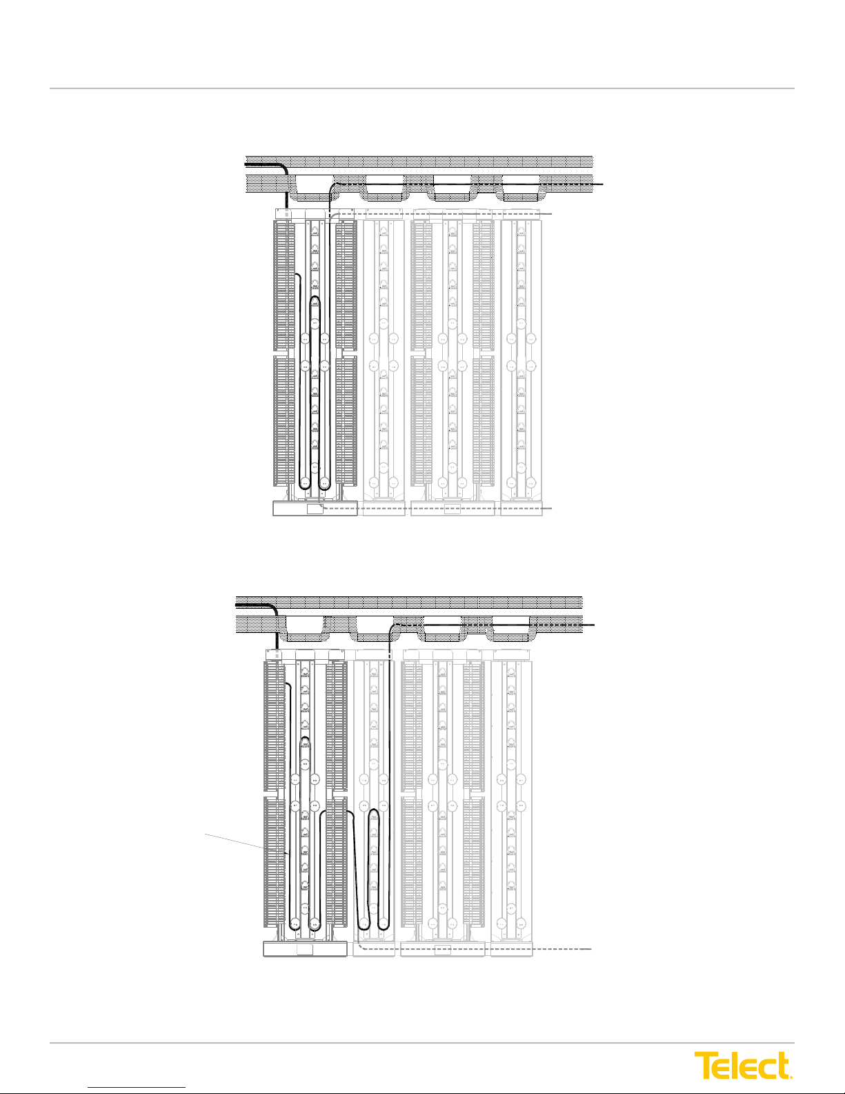
CMS
Alternate Route
Alternate Route
Ladder Rack
IFC Cabling to Rear
(Outboard Side)
of IFC Module
Preferred Pigtail
Route from Inboard
Side of IFC Module
Via CMS to Network
Element
Figure 7 - Interconnect IFC to NE33
User Manual
IFC Cabling to Rear
(Outboard Side)
of IFC Module
Ladder Rack
CMS
Figure 7 - Interconnect IFC to NE33
Preferred Pigtail
Route from Inboard
Side of IFC Module
Via CMS to Network
Element
Alternate Route
Alternate Route
IFC C abling to R ea r
(Outboard Side)
of IFC Module
Patch Cord
Ladder Rack
CMS
Figure 8 - Cross-Connect NFC to IE
Preferred Pigtail
Route from Outboard
Side of NE Module
Via CMS to Network
Element
Alternate Route
© Telect, Inc., All Rights Reserved, 12.7.16 v.4
1.509.926.6000 :: telect.com
8
Page 15
Advanced Distribution Frame (ADF) Systems
1.2.2 ADF ICs (after Trough Removed)
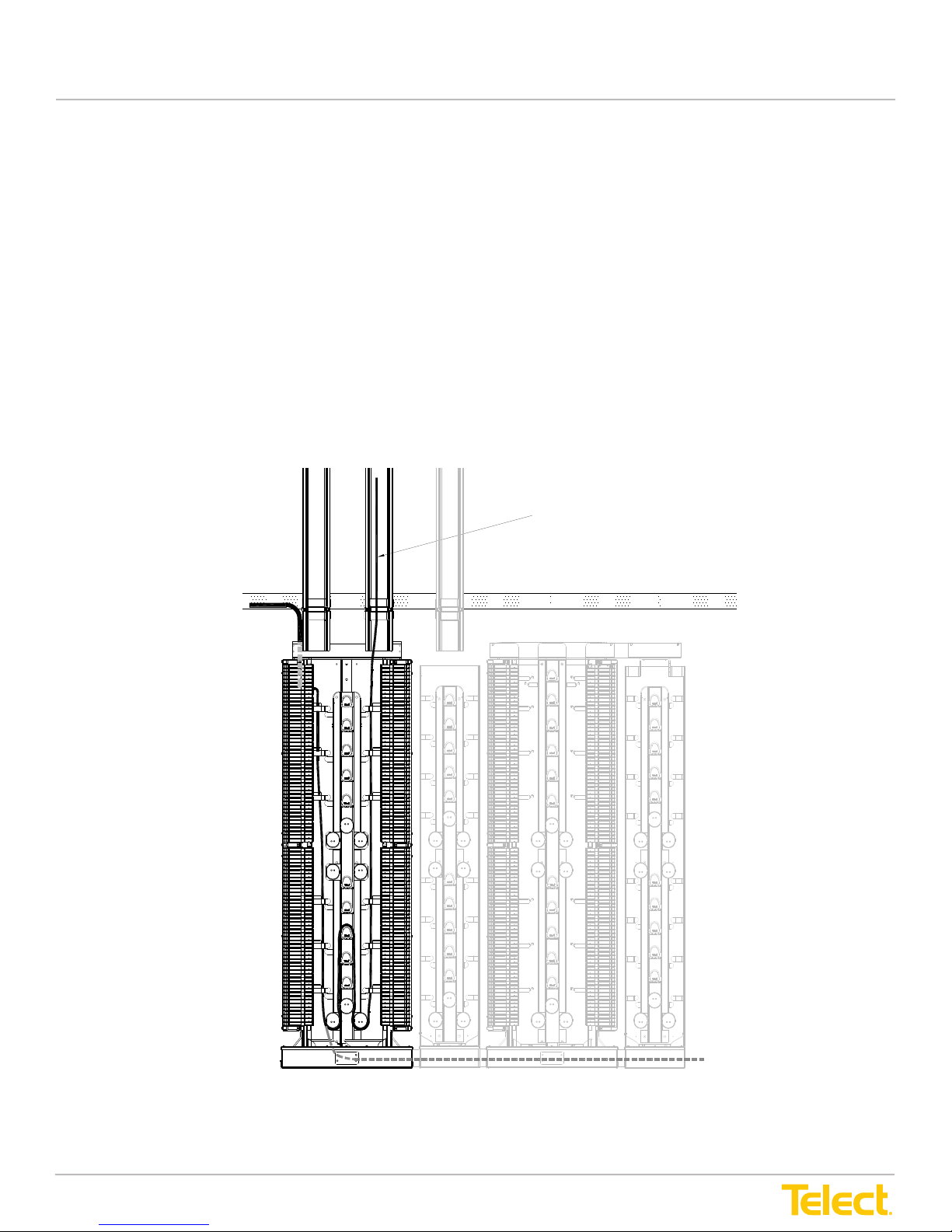
ADF Interconnect (IC) bays are physically similar to but functionally quite different from the ADF
XI bays.
To convert XI to IC, remove the top trough. With the top trough removed, the overhead access to
the patch area of a Main and ISP ADF ICs is confined to a center drop from an overhead cable
management system. Both Main and ISP ADF ICs feature an interconnected bottom trough for
routing cable between the ADF IC bays.
ADF XI and IC bays can be used in the same lineup; cross-aisle connections between lineups
are common applications for ADF ICs.
The following figures show a few typical interconnection schemes between IFC and network
element (NE) cabling. In these examples, IFC routing to the rear of the IFC ADF modules is from
the facilities ladder rack with NE cabling dropped from an overhead cable management system
(CMS).
User Manual
1.2.2 ADF ICs (after Trough Removed)
ADF Interconnect (IC) bays are physically similar to but functionally quite different from the ADF XI bays.
To convert XI to IC, remove the top trough. With the top trough removed, the overhead access to the patch
area of a Main and ISP ADF ICs are conned to a center drop from an overhead cable management system.
Both Main and ISP ADF ICs feature an interconnected bottom trough for routing cable between the ADF
IC bays.
ADF XI and IC bays can be used in the same lineup; cross-aisle connections between lineups are common
applications for ADF ICs.
The following gures show a few typical interconnection schemes between IFC and network element (NE)
cabling. In these examples, IFC routing to the rear of the IFC ADF modules is from the facilities ladder rack
with NE cabling dropped from an overhead cable management system (CMS).
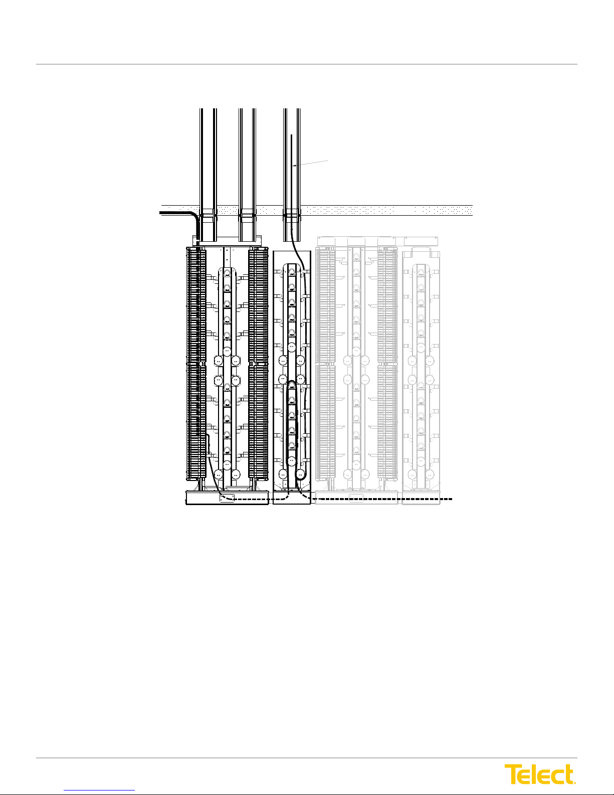
CMS
(Optional)
IFC Cabling to Rear
(Outboard Side) of
of IFC Module
Ladder Rack
Preferred Pigtail Route from
Inboard Side of IFC Module Via
CMS to Network Element
Figure 9 - IFC to NE Interconnection Using ADF ICs in an ADF Lineup
© Telect, Inc., All Rights Reserved, 12.7.16 v.4
1.509.926.6000 :: telect.com
Alternate Route
9
Page 16
Advanced Distribution Frame (ADF) Systems
User Manual
IFC Cabling to Rear
(Outboard Side)
of IFC Module
CMS
(Optional)
Preferred Pigtail Route from Inboard Side of
IFC Module Via CMS to Network Element
Ladder Rack
Figure 10 - IFC to NE Interconnection Using ADF ICs in an ADF Lineup (with ISP Storage)
© Telect, Inc., All Rights Reserved, 12.7.16 v.4
1.509.926.6000 :: telect.com
Alternate Route
10
Page 17
Advanced Distribution Frame (ADF) Systems
1.3 ADF Modules
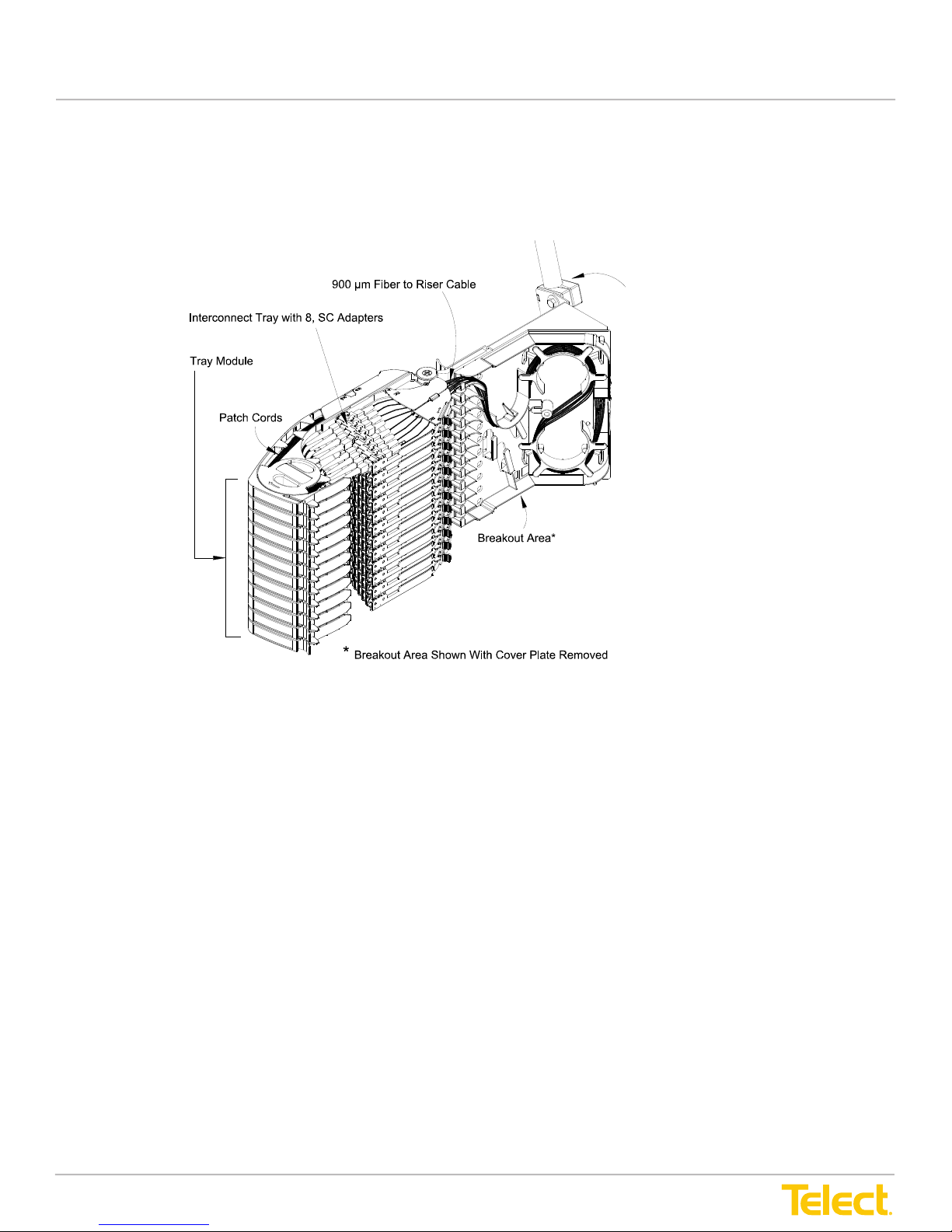
Normally, Main ADFs are dedicated to either interconnection between intrafacility cabling and
facility elements, or cross-connection between the network elements. The difference lies in the
type of ADF modules on the right and left sides of the Main ADF Panels.
User Manual
1.3 ADF Modules
Normally, Main ADFs are dedicated to either interconnection between intrafacility cabling and facility elements
or cross-connection between the network elements. The difference lies in the type of ADF modules on the right
and left sides of the Main ADF Panels.
Clamp on Rear of Breakout Box
Secures Riser Cable to Module
Figure 11 - Outboard View of Right-Hand, Intrafacility Cable (IFC) Module
© Telect, Inc., All Rights Reserved, 12.7.16 v.4
1.509.926.6000 :: telect.com
11
Page 18

Advanced Distribution Frame (ADF) Systems
Figure 12 - Outboard View of Right-Hand, Network Element (NE) Module
User Manual
Figure 12 - Outboard View of Right-Hand, Network Element (NE) Module
.
Figure 13 - Fan-Out Module
ADF modules are available for accommodating ribbon cabling, combining patching with ber splicing, splitting
and other capabilities. The modules come in right- and left-side versions, for the right and left sides of the
Main ADF.
© Telect, Inc., All Rights Reserved, 12.7.16 v.4
1.509.926.6000 :: telect.com
12
Page 19
Advanced Distribution Frame (ADF) Systems
Three types of modules are available, depending on application:
1. The IntraFacility Cable (IFC) module contains a breakout area for routing standard 900
micron fiber cabling from a rear-side clamp holding the riser cable. The 900-micron fibers
are routed to optical adapters in the trays.
2. The Network Element (NE) module contains raceways for routing standard 2-mm network
element cabling to the adapters.
3. The Fan-Out (FO) module accommodates up to 12 different multifiber cable
clamp positions.
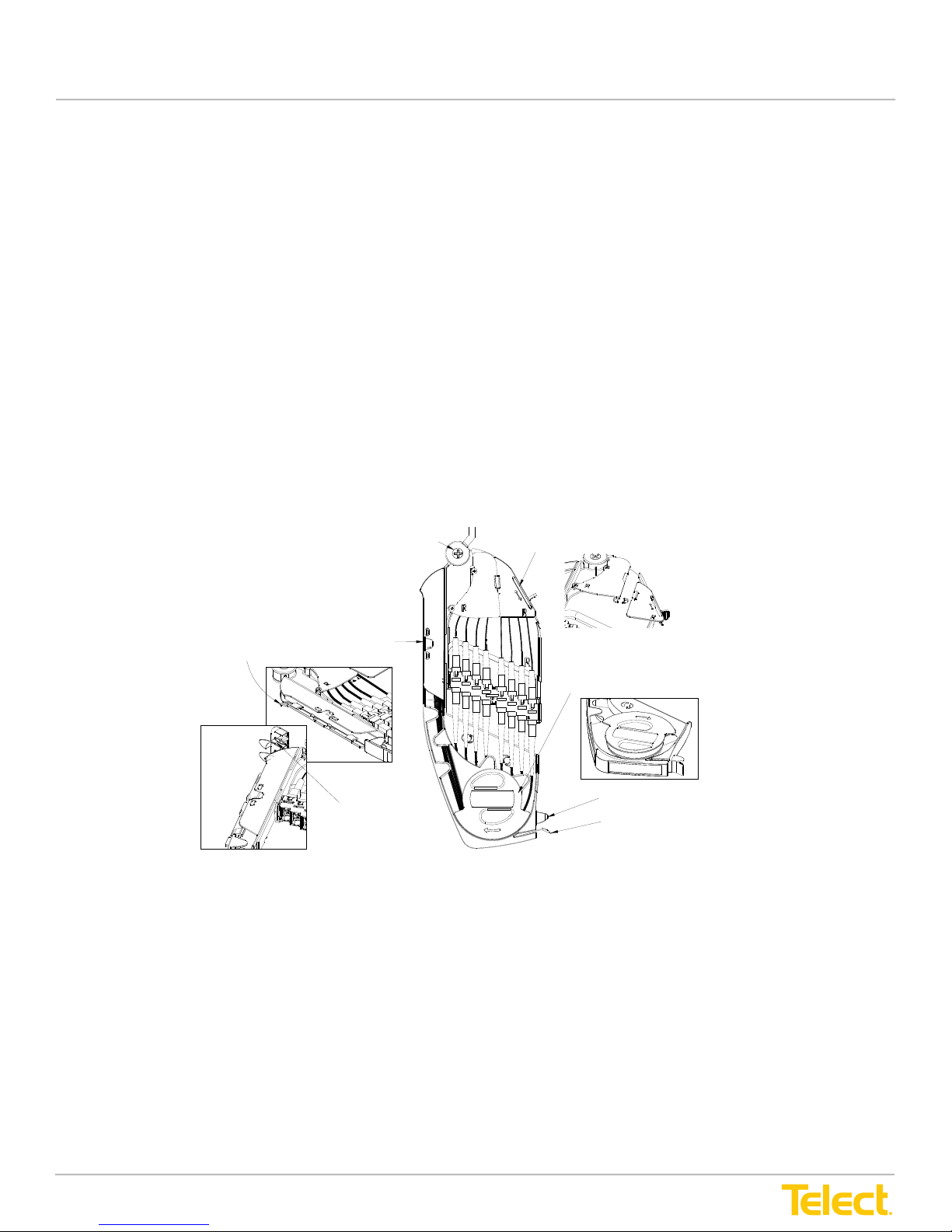
Individual trays swing toward the inboard area of the Main ADF to simplify the cabling process.
The trays contain a moveable adapter bridge that slides toward the rear when the tray is opened.
The sliding bridge provides slack management as the tray opens.
Fiber cables from the breakout area or raceways are routed under a cover to
the rear side of the
adapters. The patch cords connected to the front side of the adapters are routed around a spool
containing a retaining flange, through a raceway, to a vertical array of cascade guides with
turnstiles attached to the inboard patch area of the ADF. A door at the end of each raceway helps
guide cables downward into the patch area
Pivot Point of Tray
.
User Manual
Three types of modules are available, depending on application:
1. The IntraFacility Cable (IFC) module contains a breakout area of routing standard 900 micron ber cabling
from a rear-side clamp holding the riser cable. The 900 micron bers are routed to optical adapters
in the trays.
2. The Network Element (NE) module contains raceways for routing standard 2mm network element cabling
to the adapters.
3. The Fan-Out (FO) module accommodates up to 12 different multi-ber cable clamp positions.
Individual trays swing toward the inboard area of the Main ADF to simplify the cabling process. The trays
contain a moveable adapter bridge that slides toward the rear when the tray is opened. The sliding bridge
provides slack management as the tray opens.
Fiber cables from the breakout area or raceways are routed under a cover to the rear side of the adapters. The
patch cords connected to the front side of the adapters are routed around a spool containing a retaining ange,
through a raceway, to a vertical array of cascade guides with turnstiles attached to the inboard patch area of
the ADF. A door at the end of each raceway helps guide cables downward into the patch area.
S lid e O pe ns to Al low IFC or N etw ork E lem en t Cab lin g
Door Flips Down to Allow Patch Cord Cabling
toPatchCordCascade
Spool Rotates to Allow Patch Cord Cabling
Patch Cord Cascade
With Turns tile
Tab
Latch
Figure 14 - Patch Tray (Physically the Same for IFC, NE and FO Modules)
© Telect, Inc., All Rights Reserved, 12.7.16 v.4
1.509.926.6000 :: telect.com
13
Page 20
Advanced Distribution Frame (ADF) Systems
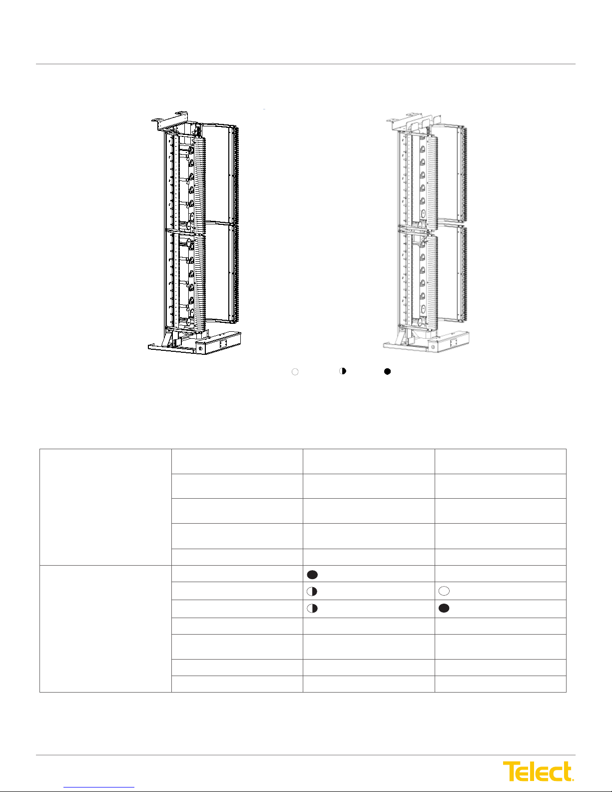
1.4 Telect ADF Feature Comparison
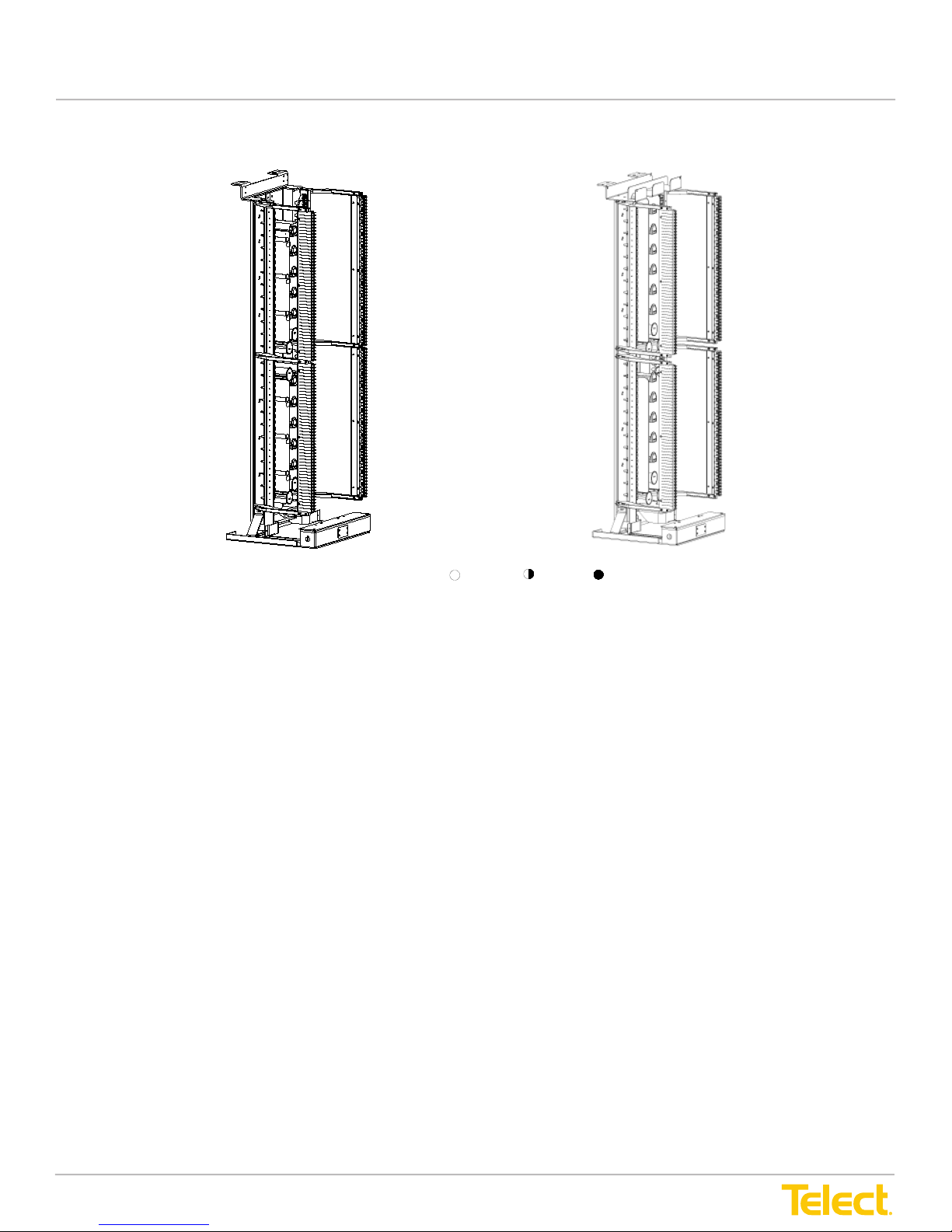
Legend: Good Better Best
User Manual
1.4 Telect ADF Feature Comparison
Telect IC
Figure 15 - ADF Comparisons
Max. Terminations/Ft
(Small Form Factor) LC
Capacity
Max. Frames in a Lineup
at Max. Density
Max. Terminations in a Lineup 16,128 (LC) 4,860 (LC)
Flexibility to Grow Yes Yes
Telect XI
1536
(2304)
2
396
(594)
7 (LC) 4 (LC)
1536
(2304)
396
(594)
(4 x 2304)
Inter-Bay Cross-Connect
Application
Single Jumper
(Cross-Connect Length)
On-frame splicing Ye s Ye s
Off-frame splicing Yes Yes
© Telect, Inc., All Rights Reserved, 12.7.16 v.4
1.509.926.6000 :: telect.com
Yes Yes
Yes
(4.5 m)
14
Yes
(4.5 m)
Page 21
Advanced Distribution Frame (ADF) Systems
Legend: Good Better Best
User Manual
Telect IC
Figure 16 - ADF Comparisons
© Telect, Inc., All Rights Reserved, 12.7.16 v.4
1.509.926.6000 :: telect.com
15
Page 22

Advanced Distribution Frame (ADF) Systems
User Manual
Telect XI Telect IC
≥ 30 mm ≥ 30 mm
Horizontal Trough Area (in2) 28.5 13.5
Cable Management
Physical Features
Exposed Cable at
Service Aisle
Port Isolation
(Port Isolation, Small Form
Factor) LC
Cable Motion Invisimanage™
Earthquake Rating Certied Certied
Flammability
(All V0 Plastics)
Circuit Designation
(in2/termination)
Laser Radiation Protection Integrated Beam Stop
None None
Maximum of 8 (12) LC Maximum of 8 (12) LC
Invisimanage™
Complete Managed
During Movement
215 215
Yes Yes
2.0 2.0
Preventing Direct
Laser Exposure
Complete Managed
During Movement
Integrated Beam Stop
Preventing Direct
Laser Exposure
1.5 Specications
1.5.1 Weight
Weights vary among ADF panels and modules. The following are approximate weights for ADF XI ETSI bays:
• Main ADFs
◊ In Box: 365 lbs. (166 kg)
◊ Installation (w/o modules): 215 lbs. (97.6 kg)
• Interbay Storage Panels
◊ In Box: 260 lbs. (118 kg)
◊ Installation: 110 lbs. (50 kg)
• ADF Modules (w/o cabling)
◊ In Box: 25 lbs. (11.4 kg)
◊ Installation: 20 lbs. (9.1 kg)
© Telect, Inc., All Rights Reserved, 12.7.16 v.4
1.509.926.6000 :: telect.com
16
Page 23

Advanced Distribution Frame (ADF) Systems
User Manual
1.5.2 Overall Dimensions
ADF Cross-Connect/Interconnect ETSI Bays:
• Main ADF
Width: 660 mm (26 inches)
Height: 2186 mm (86 inches)
Depth: 595 mm (23 inches)
• Interbay Storage Panel
Width: 300 mm (12 inches)
Height: 2186 mm (86 inches)
Depth: 595 mm (23 inches)
Cross-Connect/Interconnect North American Bays
• Main ADF
Width: 24 inches (600 mm)
Height: 84 inches (2134 mm)
Depth: 24 inches (610 mm)
• Interbay Storage Panel
Width: 12 inches (300 mm)
Height: 84 inches (2134 mm)
Depth: 24 inches (610 mm)
© Telect, Inc., All Rights Reserved, 12.7.16 v.4
1.509.926.6000 :: telect.com
17
Page 24

Advanced Distribution Frame (ADF) Systems
User Manual
This page intentionally left blank.
© Telect, Inc., All Rights Reserved, 12.7.16 v.4
1.509.926.6000 :: telect.com
18
Page 25
Advanced Distribution Frame (ADF) Systems
Chapter 2: Applications
Advanced Distribution Frame (ADF) Systems
This section covers fundamental cross-connection and interconnection applications using ADF
XI bays. Other applications are possible. Some applications may be better suited for the ADF IC
bays, depending on access to, routing, and density of cabling.
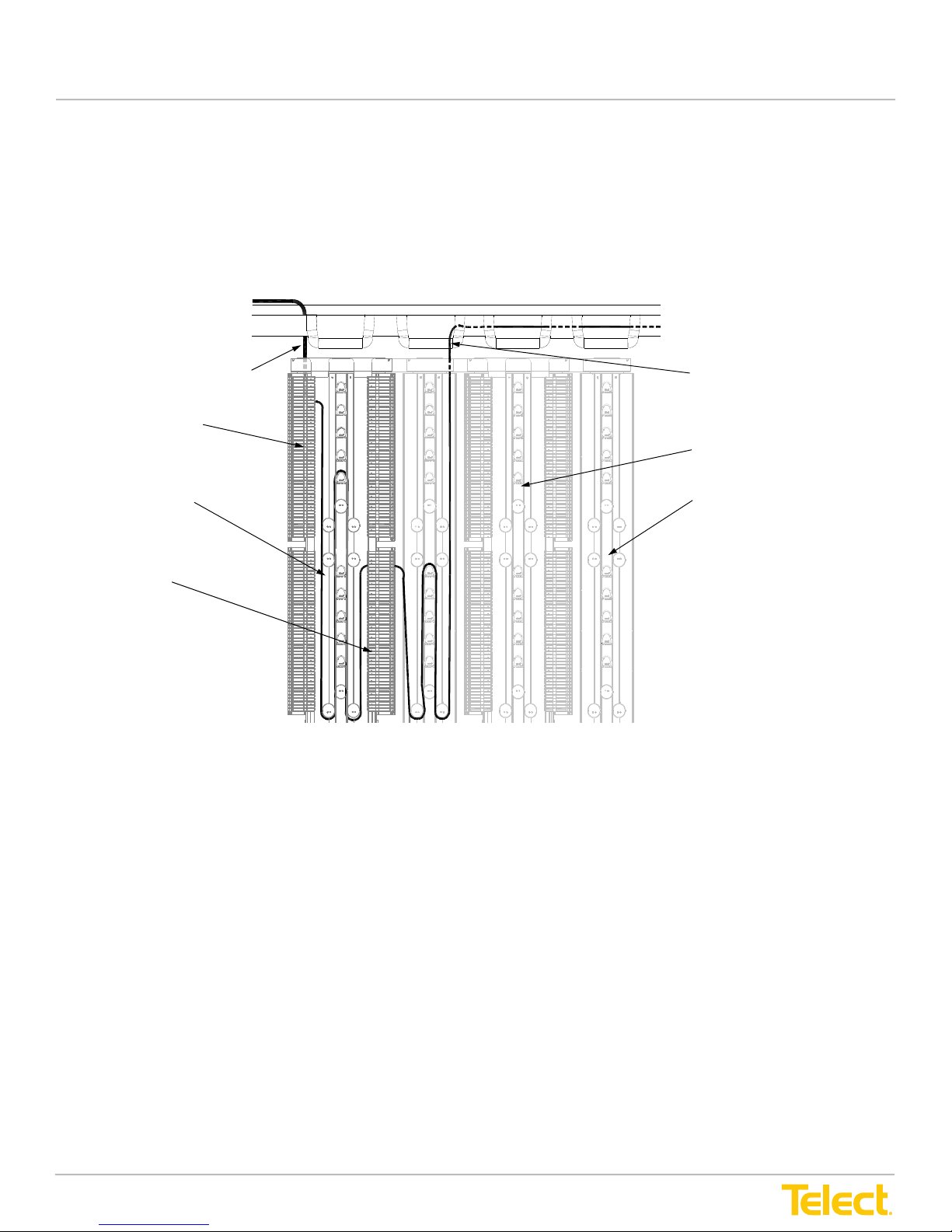
2.1 Cross-Connect - IFC to NEs
User Manual
Chapter 2: Applications
This section covers fundamental cross-connection and interconnection applications using ADF XI bays. Other
applications are possible. Some applications may be better suited for the ADF IC bays, depending on access
to routing and density of cabling.
2.1 Cross-Connect - IFC to NEs
CMS
IntraFacility Cable (IFC)
IFC Modules
4.5 m Cross-connect
Patch Cord
Network Element (NE)
Modules
Network Element
Patch Cord
Main ADF
InterBay Storage
Panel (ISP)
Figure 17 - Cross-Connect - IFC to NEs
Fundamentals of this cross-connect are as follows:
• IFC (IntraFacility Cable) modules are available for either the right or left side of the Main ADF bay
• IFC comes in from ladder racking (or from oor) and is broken out and presented to the back side
of IFC modules
• NE (Network Element) modules should be installed opposite associated IFC modules
• Interbay Storage Panel (ISP) is required with NE modules
• Patch cords from NE’s come into ISP from CMS (Cable Management System) and are presented to the
back side of NE modules; the excess is stored on the ISP
• 4.5m patch cords cross-connect IFC ber to NE ber, with cable stored on the Main ADF bay
• Additional ADF bays can be added to the lineup but should maintain IFC and NE module orientation
© Telect, Inc., All Rights Reserved, 12.7.16 v.4
1.509.926.6000 :: telect.com
19
Page 26
Advanced Distribution Frame (ADF) Systems
• Additional ADF bays can be added to the line-up but should maintain IFC and NE
module orientation.
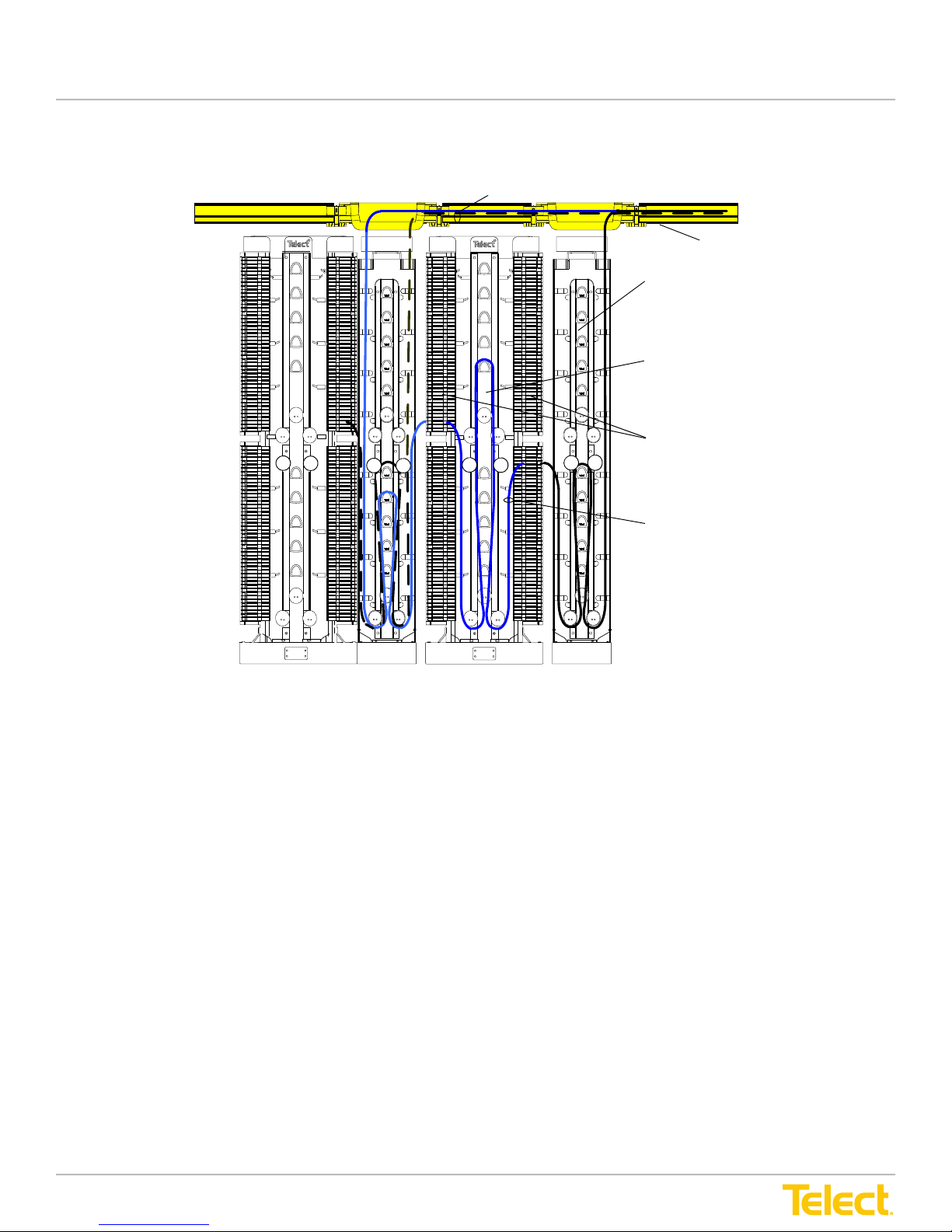
2.2 Cross-Connect - NEs to NEs
Network Element Patch Cords
User Manual
2.2 Cross-Connect - NEs to NEs
WaveTrax™ Cable
Management System
InterBay Storage
Panel (ISP)
Main ADF
NE Modules
4.5 m Cross-connect
Patch Cord
Figure 18 - Cross-Connect - NEs to NEs
Fundamentals of this cross-connect are as follows:
• NE (Network Element) modules are available for both sides of the Main ADF
• When cross-connecting NE’s, the system requires an ISP (Interbay Storage Panel) on both sides of the
Main ADF bay
• NE patch cords are routed from the CMS (Cable Management System) into the ISP and presented to the
back side of an adapter; the same process is done on the other side of the Main ADF bay
• A 4.5m patch cord cross-connects the two NE bers and the cable is stored on the Main ADF bay
• The ISP is used so that NE’s can be routed in both directions in the ISP
© Telect, Inc., All Rights Reserved, 12.7.16 v.4
1.509.926.6000 :: telect.com
20
Page 27
Advanced Distribution Frame (ADF) Systems
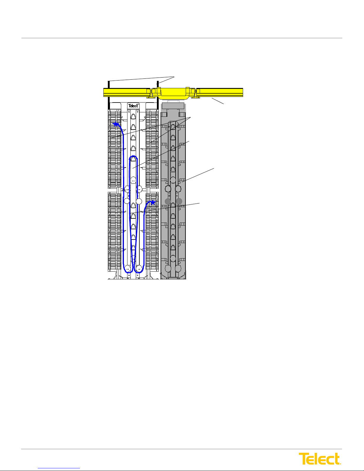
2.3 Cross-Connect - IFC to IFCs
InterFacility Cable (IFC)
User Manual
2.3 Cross-Connect - IFC to IFCs
WaveTrax™ Cable
Management System
IFC Modules
Main ADF
InterBay Storage Panel (ISP)
4.5 m Cross-connect
Patch Cord
Figure 19 - Cross-Connect - IFC to IFCs
Fundamentals of this cross-connect are as follows:
• IFC (IntraFacility Cable) modules are mounted on both sides of the Main ADF bay
• The IFC comes in from ladder racking (or from oor) and is broken out and presented to the back sides of
IFC modules
• 4.5m patch cords cross-connect IFC ber to IFC ber, with cable stored on the Main ADF bay
© Telect, Inc., All Rights Reserved, 12.7.16 v.4
1.509.926.6000 :: telect.com
21
Page 28
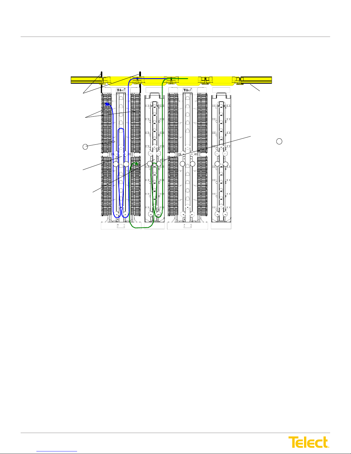
Advanced Distribution Frame (ADF) Systems
2.4 Interconnect - IFC to IFC
User Manual
2.4 Interconnect - IFC to IFC
IntraFacility
Cable (IFC)
IFC Modules
Interconnect
Patch Cord A
Main ADF
InterBay Storage
Panel (ISP)
WaveTrax™ Cable
Management System
Interconnect
Patch Cord B
Figure 20 - Interconnect - IFC to IFC
Fundamentals of this cross-connect are as follows:
• IFC (IntraFacility Cable) modules (only) are mounted on both sides of the Main ADF bay
• The IFC comes in from ladder racking and is broken out and presented to the back side of the IFC modules
• On one side of the Main ADF bay, the patch cords are routed from the CMS (Cable Management System)
into the frame and presented to the front side of an adapter; excess patch cord length is stored on the Main
ADF bay (Interconnect Patch Cord A)
• You may use an ISP (Interbay Storage Panel) to manage the patch cords on the opposite side of the Main
ADF bay
• Patch cords are routed into the ISP from the CMS and presented to the front side of the adapter; this
requires the patch cords to be routed through the bottom trough (Interconnect Patch Cord B)
© Telect, Inc., All Rights Reserved, 12.7.16 v.4
1.509.926.6000 :: telect.com
22
Page 29
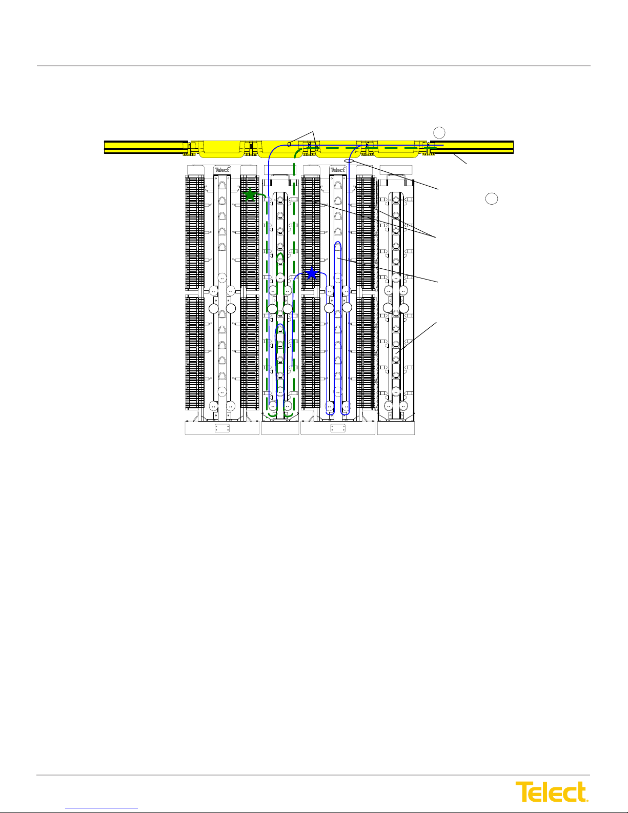
Advanced Distribution Frame (ADF) Systems
2.5 Interconnect - NEs to NEs
User Manual
2.5 Interconnect - NEs to NEs
Network Element Patch Cords A
WaveTrax™ Cable
Management System
Network Element
Patch Cord B
Network Element Modules
Main ADF
InterBay Storage Panel (ISP)
Figure 21 - Interconnect - NEs to NEs
Fundamentals of this cross-connect are as follows:
• NE (Network Element) modules (only) are mounted on both sides of the Main ADF bay
• ISPs (Interbay Storage Panels) are required
• Back-side NE patch cords come in from the CMS (Cable Management System) into the ISP and are
presented to the back side of the NE modules (Network Element Patch Cords A)
• Front-side NE patch cords are routed into the frame from the CMS and presented to the front side of the
adapter (Network Element Patch Cord B)
© Telect, Inc., All Rights Reserved, 12.7.16 v.4
1.509.926.6000 :: telect.com
23
Page 30
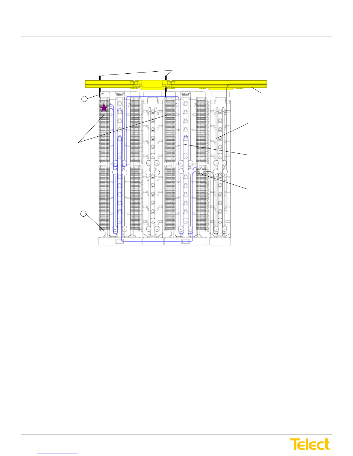
Advanced Distribution Frame (ADF) Systems
2.6 Interframe Cross-Connecting
User Manual
2.6 Interframe Cross-Connecting
IntraFacility Cables (IFC)
WaveTrax™ Cable
Upper Trough B
IFC Modules
Management System
InterBay Storage
Panel (ISP)
Main ADF
Network Element Module
Lower Trough A
Figure 22 - Interframe Cross-Connecting
• Interframe connections can be done in two ways:
1. By routing the patch cord between the two frames via the Lower Trough (A)
2. By routing the patch cord through the Upper Trough (B)
• The excess cross-connect patch cord length is stored in the Main ADF bays
• For NE (Network Element) patch cord isolation and safety, storing cross-connect patch cords in the ISP
(Interbay Storage Panel) is not recommended
• Connect the origin, then route to the cross-connecting point and store any extra cable on the Main ADF bay
nearest the second connection
© Telect, Inc., All Rights Reserved, 12.7.16 v.4
1.509.926.6000 :: telect.com
24
Page 31
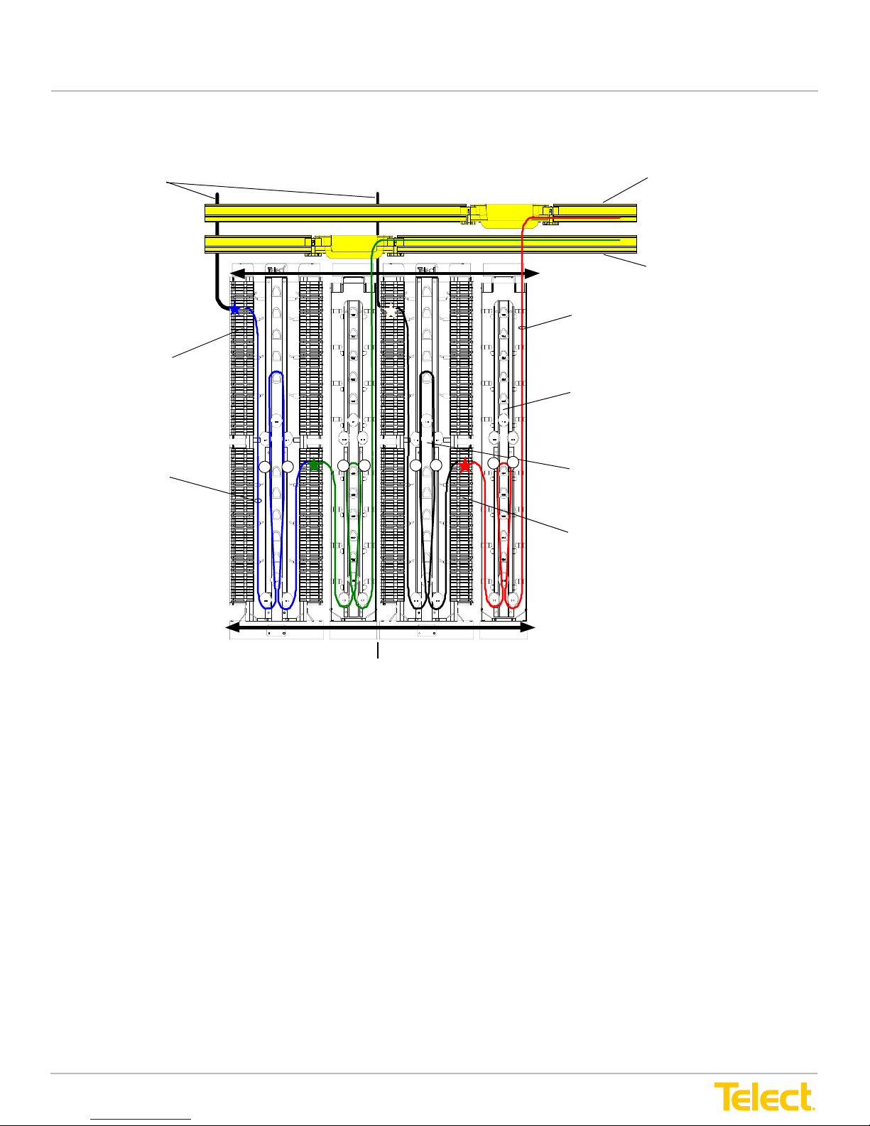
Advanced Distribution Frame (ADF) Systems
2.7 Cross-Connect - IFC to NEs - Working/Protect
User Manual
2.7 Cross-Connect - IFC to NEs - Working/Protect
IntraFacility Cable (IFC)
IFC Module
4.5 m Cross-connect
Patch Cord
Protect Routing
Network Element
Patch Cord
InterBay Storage
Panel (ISP)
Main ADF
Network Element Module
Protect Cable
Management
System
Working Cable
Management System
Working ADF
Protect ADF
Working Routing
Figure 23 - Cross-Connect - IFC to NEs - Working/Protect
Separate lineups provide complete isolation of bers inside the Main ADF bay. When that cannot be done, the
following are options:
• IFC (IntraFacility Cable) and NE (Network Element) modules should be laid out so that an ISP (Interbay
Storage Panel) contains only one type of ber – Working or Protect
• Working and Protect interpanel cross-connects should be separated in the top and bottom troughs
© Telect, Inc., All Rights Reserved, 12.7.16 v.4
1.509.926.6000 :: telect.com
25
Page 32
Advanced Distribution Frame (ADF) Systems
2.8 Cross-Connect - IFC to NEs - Working/Protect - Standalone
User Manual
2.8 Cross-Connect - IFC to NEs - Working/Protect - Standalone
WaveTrax™ Cable
Management System
IntraFacility Cables (IFC)
3.6 m Cross-connect
Patch Cords
IFC Modules
Main ADF
Protect
Working
Protect Routing
InterBay Storage Panel (ISP)
Network Element
Patch Cords
Protect
Network Element Modules
Working
Working Routing
Figure 24 - Cross-Connect - IFC to NEs - Working/Protect - Standalone
This option is only for a standalone Main ADF bay:
• IFC (IntraFacility Cable) modules should be installed on the side opposite the ISP (Interbay Storage Panel)
• Working bers are either on the top or the bottom half of the Main ADF bay. Protect bers are placed in the
opposite half
• Interpanel routing should use the upper or lower trough corresponding to the module location
• 3.6m cross-connect patch cords – shorter cable lengths are required in working/protect applications
© Telect, Inc., All Rights Reserved, 12.7.16 v.4
1.509.926.6000 :: telect.com
26
Page 33
Advanced Distribution Frame (ADF) Systems
Chapter 3: Frame Installation
Advanced Distribution Frame (ADF) Systems
3.1 Installation Considerations
ALERT
!
ALERT! Only qualified technicians may install and maintain this product.
ALERT! Do not stand on utility or fiber cable troughs at the base of ADFs.
3.1.1 Location & Space
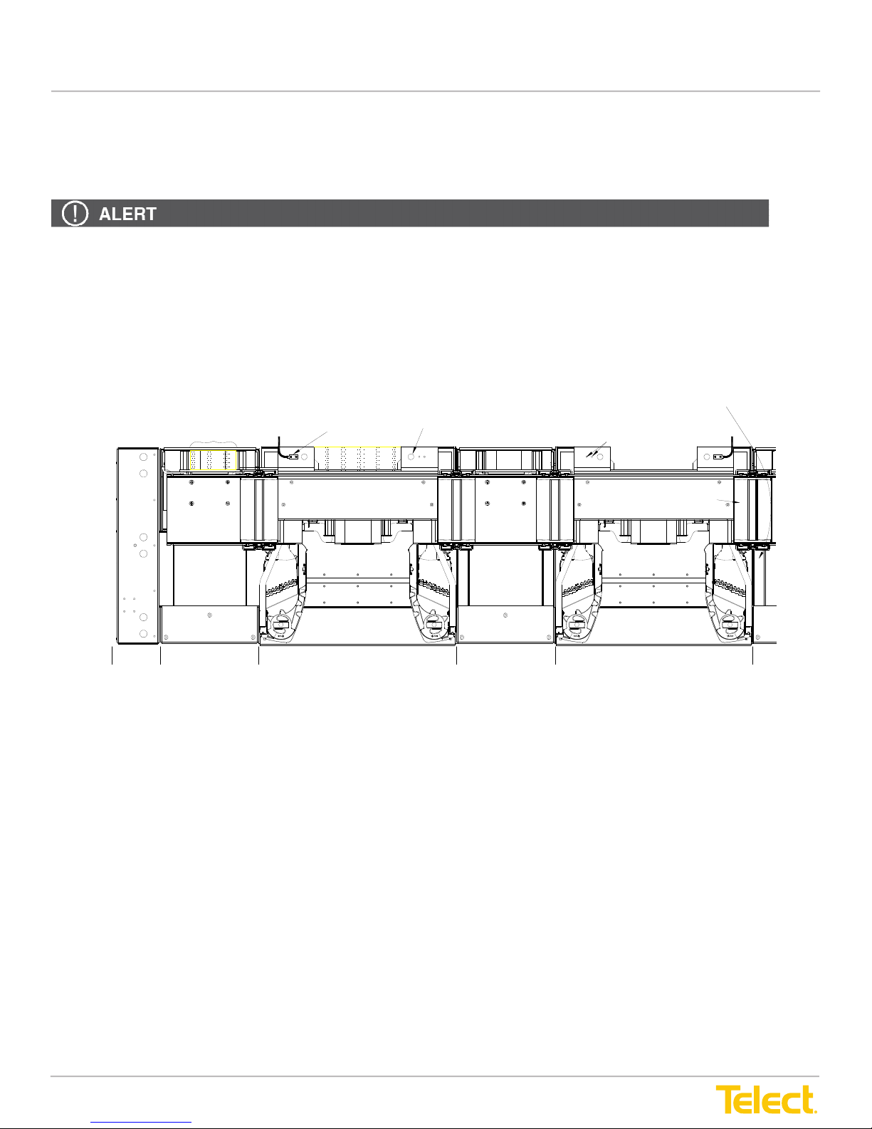
The Main ADF and InterBay Storage Panel require space in front and at rear for access to
cabling. Refer to Figure 25, below. Choose a location in compliance with local operating
company requirements.
Rear Aisle Access
User Manual
Chapter 3: Frame Installation
3.1 Installation Considerations
ALERT! Only qualied technicians may install and maintain this product.
ALERT! Do not stand on utility or ber cable troughs at the base of ADFs.
3.1.1 Location & Space
The Main ADF and Interbay Storage Panel require space in front and at rear for access to cabling. Refer to
Figure 25, below. Choose a location in compliance with local operating company requirements.
Lower ADF Trough Junction
Reserve Area Above
for Patch Cord Drop
Ground Lug and #6 AWG*
(1 GND per Main ADF)
Reserve Area Above
for IFC Drop
17.5 mm, hole dia. for allthrea d mounting of CMS or ladder rack
M5 Holes for Grounding
Upper ADF Trough Junction
End Panel
3.1.2 Tools & Equipment
The following tools are required for installing ADFs:
• 18mm (or 23/32 in.) masonry bit
• 40 N•m torque wrench with a 19 mm box or open end (19mm socket can be used if the socket is at least 54
mm deep)
• Broad blade screwdriver (~8 mm or 5/16 in. blade width)
• Horizontal or plumb level (optional)
• Isolation pad (if required at base of frame)
• # 1 or # 2 Phillips screwdrivers (screwdrivers for cross-recessed screws) for attaching lower
trough junctions
ADF ISP ADF ISPMain ADF Main ADF
Figure 25 - Installation Location
© Telect, Inc., All Rights Reserved, 12.7.16 v.4
1.509.926.6000 :: telect.com
27
Page 34

Advanced Distribution Frame (ADF) Systems
User Manual
3.2 Inspection
Telect is not liable for shipping damage.
Keep the container until you have checked equipment operation. If you experience any kind of problem, call
Telect at 509-926-6000. Use the original, undamaged container if you are instructed to return the Main ADF,
Interbay Storage Panel or ADF Modules to Telect.
If a shipping container is damaged, keep it for the carrier’s inspection. Notify the carrier and call Telect at
509-926-6000.
3.3 Main & Interbay Storage Panel Installation
3.3.1 Unpacking Main & Interbay Storage Panels
Main ADF container: 42" x 36" x 96" (107 mm x 92 mm 244 mm) Approximate loaded weight: 365 lbs. (166 kg)
Interbay Storage Panel container: 42" x 36" x 96" (107 mm x 92 mm x 244 mm)
Approximate loaded weight: 260 lbs (118 kg)
The container for either the Main or Interbay Storage Panel contains:
• Pre-assembled ADF
• Template for mounting ADF to a oor
• Trough cover
• User manual
• One 8 in. upper trough junction
• One lower trough ADF junction
• Tie plate and M6 x 12 bolts to secure adjacent ADFs in the lineup
If necessary, use a forklift to move the “Main ADF” and/or “Interbay Storage Panel” container to the installation
site. Open the container and check the contents against the packing list. Contact Telect if anything is missing.
© Telect, Inc., All Rights Reserved, 12.7.16 v.4
1.509.926.6000 :: telect.com
28
Page 35
Advanced Distribution Frame (ADF) Systems
3.3.2 Installing Main & InterBay Storage Panels Directly on a Concrete Floor
Each Telect Anchoring Kit (sold separately) contains concrete anchors, threaded studs, and
fastening hardware to anchor and secure the base of one Main or InterBay Storage Panel to a
concrete floor. Refer to “Bays and Accessories” on page 61 of this manual for part numbers, or
see telect.com for ordering information.
Procedure steps:
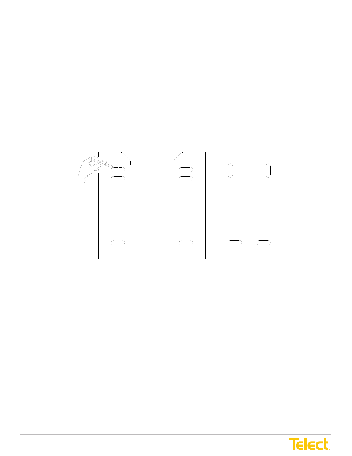
3. Use the template included with the ADF to lay out a 4-hole pattern on the concrete floor. (Use
th
e outermost locations for anchor holes.)
User Manual
3.3.2 Installing Main & Interbay Storage Panels Directly on a Concrete Floor
Each Telect Anchoring Kit (sold separately) contains concrete anchors, threaded studs and fastening hardware
to anchor and secure the base of one Main or Interbay Storage Panel to a concrete oor. Refer to “Bays and
Accessories” on page 61 of this manual for part numbers or see Telect.com for ordering information.
Procedure Steps:
1. Use the template included with the ADF to lay out a 4-hole pattern on the concrete oor.
(Use the outermost locations for anchor holes.)
Main ADF Template InterBay Storage Panel
Template
Figure 26 - ADF and Interbay Storage Panel Installation Template
2. Mark and then drill four holes for each Main Panel and ISP.
© Telect, Inc., All Rights Reserved, 12.7.16 v.4
1.509.926.6000 :: telect.com
29
Page 36
Advanced Distribution Frame (ADF) Systems
5. Follow the instructions supplied with the anchor kit(s). Shim as required and use the isolation
pad and bushings (if required) to electrically isolate the panels from the floor structure.
Main ADFMain ADF
D
A
D
A
D
User Manual
3. Follow the instructions supplied with the anchor kit(s). Shim as required and use the isolation pad and
bushings (if required) to electrically isolate the panels from the oor structure.
C
C
C
E
E
F
F
F
G
G
G
I
I
I
H
H
H
E
O
O
B
B
B
O
M
M
M
N
N
N
B
B
B
P
P
P
J
J
J
J
J
K
K
K
A
J
K
K
K
L
L
L
InterBay Storage Panel
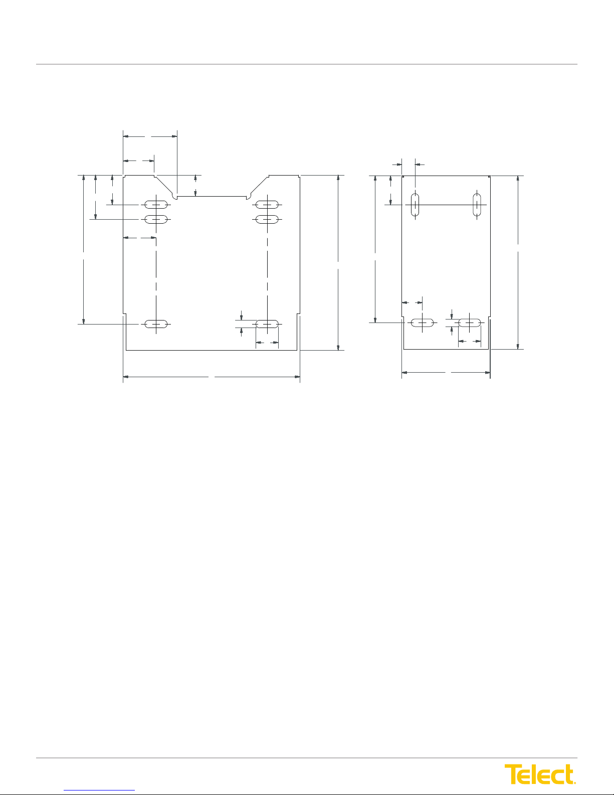
Figure 27 - ADF and Interbay Storage Panel Footprints
The procedure is complete.
© Telect, Inc., All Rights Reserved, 12.7.16 v.4
1.509.926.6000 :: telect.com
30
Page 37

Advanced Distribution Frame (ADF) Systems
User Manual
3.3.3 Table of Footprint Dimensions
ETSI XI NA ADF XI
Main ADF ISP End Panel Main ADF ISP End Panel
A 600 mm 26"
B 600 mm 600 mm 24" 24"
C 105 mm 4.1"
D 180 mm 7.2"
E 72 mm 3.4"
F 100 mm 4.5"
G 150 mm 6.5"
H 505 mm 20.4"
I 112 mm 5.6"
J 26 mm 26 mm 1" 1"
K 76 mm 76 mm 3" 3"
L 300 mm 12"
M 45 mm 1.9"
N 100 mm 4.6"
O 500 mm 20.3"
P 70 mm 2.8"
© Telect, Inc., All Rights Reserved, 12.7.16 v.4
1.509.926.6000 :: telect.com
31
Page 38
Advanced Distribution Frame (ADF) Systems
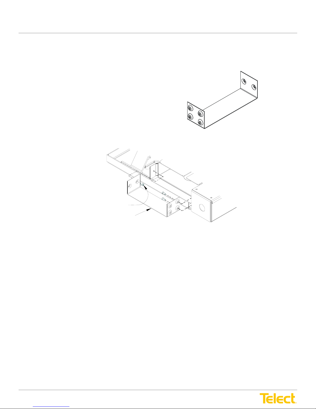
3.3.4 Installing Lower Trough Junction
Use M6 screws to attach the Main ADFs to the ISPs.
Figure 28 - Lower ADF Junction
.
User Manual
3.3.4 Installing Lower Trough Junction
Use M6 screws to attach the Main ADFs to the ISPs.
Figure 28 - Lower ADF Junction
Three M6 Screws Secure
Each Edge to an ADF
Lower Trough Junction
Figure 29 - Lower Trough Junction Being Secured to the Main ADF XI
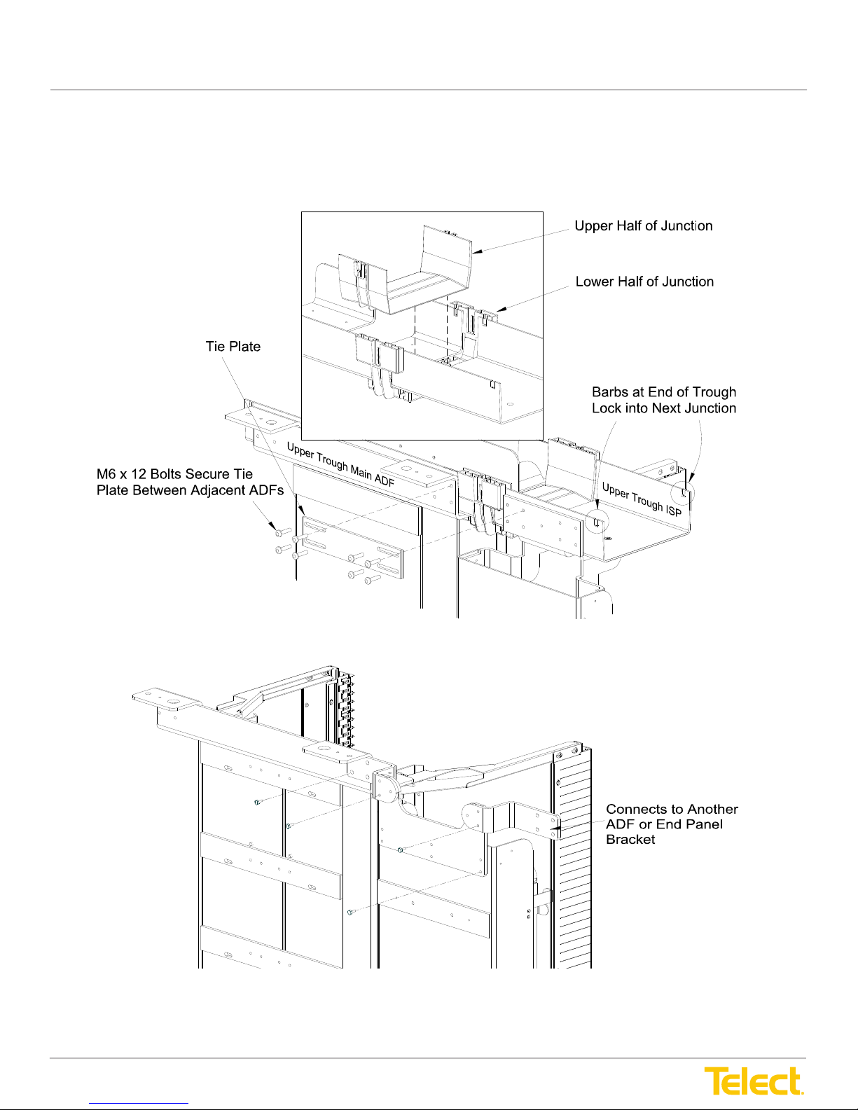
3.3.5 Installing Upper Trough Junction on ADF XI Bays
Connect the adjacent 8 in. upper ADF troughs using the plastic junction provided.
The upper ADF troughs are sandwiched between the upper and lower halves of this two-part, 8 in. junction.
The prongs on the bottom of the upper half snap and lock into corresponding holes in the lower half.
NOTE: If you need to remove the junction, press in on the two pairs of prongs on the underside of the junction
to separate the two halves.
© Telect, Inc., All Rights Reserved, 12.7.16 v.4
1.509.926.6000 :: telect.com
32
Page 39
Advanced Distribution Frame (ADF) Systems
3.3.6 Securing ADF to the Lineup
A tie plate with two pairs of slotted holes and M6 x 12 bolts are provided to tie adjacent ADFs in
the line up. Leave the bolts finger-tight until the complete lineup is assembled, then tighten them
all. Follow the instructions included with the end panels for attaching the end panel to the last ISP
in the lineup.
3.3.6 Securing ADF to the Lineup
A tie plate with two pairs of slotted holes and M6 x 12 bolts are provided to tie adjacent ADFs in
the line up. Leave the bolts finger-tight until the complete lineup is assembled, then tighten them
all. Follow the instructions included with the end panels for attaching the end panel to the last ISP
in the lineup.
Figure 30 - Rear Corner View of an ADF XIs in an ADF Lineup
User Manual
3.3.6 Securing ADF to the Lineup
A tie plate with two pairs of slotted holes and M6 x 12 bolts are provided to tie adjacent ADFs in the line up.
Leave the bolts nger-tight until the complete lineup is assembled, then tighten them all. Follow the instructions
included with the end panels for attaching the end panel to the last ISP in the lineup.
Figure 30 - Rear Corner View of an ADF XIs in an ADF Lineup
Figure 31 - Rear Corner View of ADF ICs in an ADF Lineup
© Telect, Inc., All Rights Reserved, 12.7.16 v.4
1.509.926.6000 :: telect.com
33
Page 40
Advanced Distribution Frame (ADF) Systems
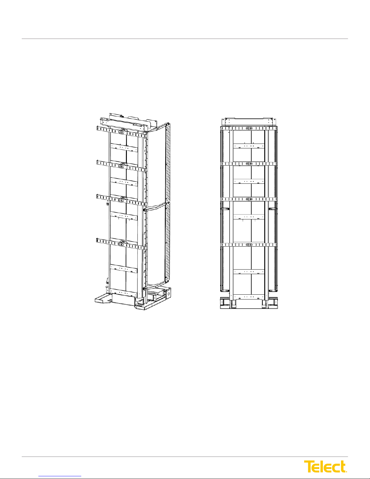
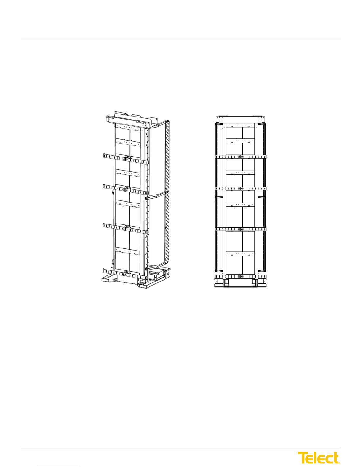
3.3.7 Installing Rear Cable Tie-Down Bars
Using the provided hardware, install the rear cable tie down bars in the desired locations. For
Top Cable Feed configurations, please refer to Figure 32, below, for the installation
recommendation. For Bottom Cable Feed configurations, please refer to Figure 33,
“Recommended Bottom Feed Configuration” on page 35, for the installation recommendation.
User Manual
3.3.7 Installing Rear Cable Tie-Down Bars
Using the provided hardware, install the rear cable tie down bars in the desired locations. For Top Cable Feed
congurations, please refer to Figure 32, below, for the installation recommendation. For Bottom Cable Feed
congurations, please refer to Figure 33, “Recommended Bottom Feed Conguration” on page 35, for the
installation recommendation.
Figure 32 - Recommended Top Feed Conguration
© Telect, Inc., All Rights Reserved, 12.7.16 v.4
1.509.926.6000 :: telect.com
34
Page 41
Advanced Distribution Frame (ADF) Systems
User Manual
Figure 33 - Recommended Bottom Feed Conguration
© Telect, Inc., All Rights Reserved, 12.7.16 v.4
1.509.926.6000 :: telect.com
35
Page 42
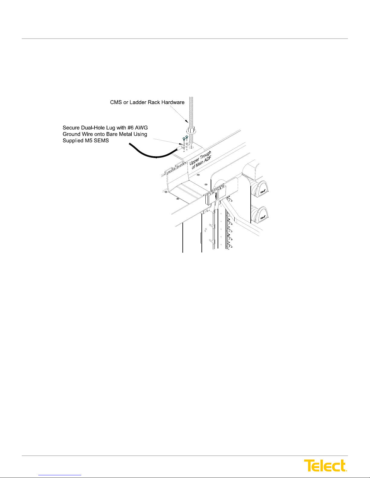
Advanced Distribution Frame (ADF) Systems
3.3.8 Installing Cable Management System (CMS)
Install the Cable Management System (CMS) as instructed by the manufacturer. If desired, use
the large (17.5 mm diameter) holes at the top of the ADFs to connect the CMS to the lineup.
User Manual
3.3.8 Installing Cable Management System (CMS)
Install the Cable Management System (CMS) as instructed by the manufacturer. If desired, use the large (17.5
mm diameter) holes at the top of the ADFs to connect the CMS to the lineup.
Figure 34 - Connect CMS to Main ADF XIs
3.3.9 Grounding ADF
The bracket at the top of the Main ADFs contain two tapped holes to mount an approved dual-hole lug with a
#6 AWG (4.75 mm) grounding wire or strap. Refer to Figure 34.
Telect recommends using one ground wire or strap per Main ADF. Grounding wires or straps are not provided
with the ADF.
3.3.10 Securing ADF Lineup
After all ADFs of a lineup are installed, torque their tie-plate bolts to 80 N•m.
3.3.11 Wiring Facility Power
Facility power (AC) can be run into and through the electrical raceway at the foot of ADF XI and IC lineups.
© Telect, Inc., All Rights Reserved, 12.7.16 v.4
1.509.926.6000 :: telect.com
36
Page 43
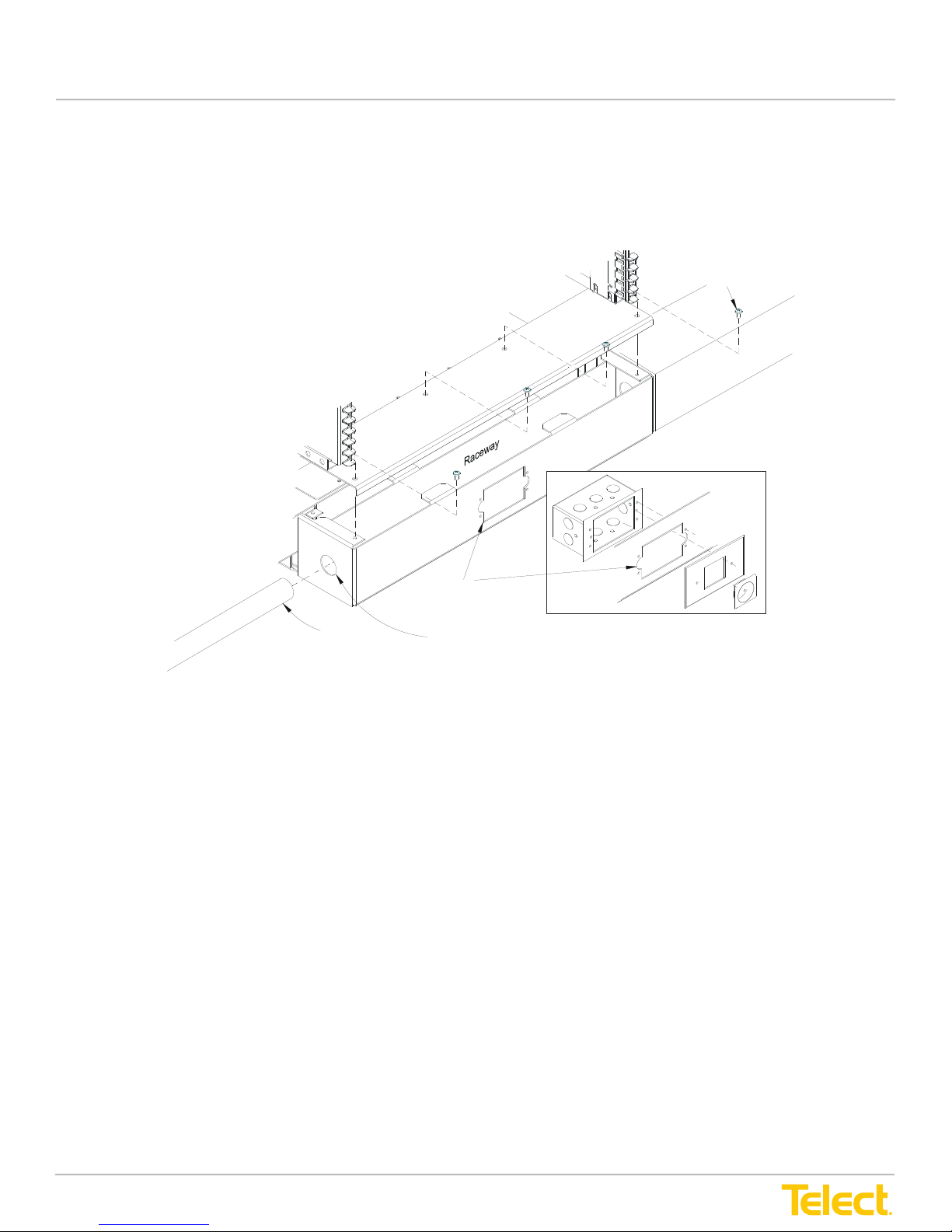
Advanced Distribution Frame (ADF) Systems
Contact your local power regulatory agency for details regarding the number and size of wires/
cables, type of receptacles and cover plates, conduit, and the like.
Access Hole for Standard
Four Screws Secure
Cover to Raceway
User Manual
Contact your local power regulatory agency for details regarding the number and size of wires/cables, type of
receptacles and cover plates, conduit and the like.
Electrical Box with Standard
Electrical Wiring Device.
Conduit
31.8 mm (1¼ in.) Hole, Dia.
Figure - 35 Electrical Raceway (Front of Base) on ADF XI and IC Lineups
© Telect, Inc., All Rights Reserved, 12.7.16 v.4
1.509.926.6000 :: telect.com
37
Page 44

Advanced Distribution Frame (ADF) Systems
User Manual
This page intentionally left blank.
© Telect, Inc., All Rights Reserved, 12.7.16 v.4
1.509.926.6000 :: telect.com
38
Page 45

Advanced Distribution Frame (ADF) Systems
User Manual
Chapter 4: Module Installation
4.1 Installation Considerations
ALERT! Only qualied technicians may install and maintain this product.
ALERT! Do not stand on utility or ber cable troughs at the base of ADFs.
4.1.1 Pre-Cabled vs. Uncabled ADF Modules
The modules can be ordered with or without pre-cabled breakout areas:
• If intrafacility cable (IFC) modules are ordered with multi-ber cabling, then either the module will be
pre-cabled or, if the cabling is too long or bulky, the module and cabling will be packed in separate
containers for installation by the user. If the module is pre-cabled, the 900 µm cables from the clamped
multi-ber cable at the rear of the module are fed through the breakout area to the far side of the
adapters in the trays.
• If network element (NE) modules are ordered with patch cords, network element cabling, the cables will
be packaged separately from the module for installation by the user.
4.1.2 Tools & Equipment Required
Phillips #2 and #3 screwdrivers (for cross-recessed screws).
4.2 Inspection
Telect is not liable for shipping damage.
Keep the container until you have checked equipment operation. If you experience any kind of problem, call
Telect at 509-926-6000. Use the original, undamaged container if you are instructed to return the tray or
module to Telect.
If the shipping container is damaged, keep it for the carrier’s inspection. Notify the carrier and call Telect at
509-926-6000.
4.3 Unpacking an ADF Module
NOTE: A “typical” ADF module and container without cabling is approximately 7 in. x 10 in. x 22 5/8 in.
(179 mm x 250 mm x 576 mm) and weighs about 20 lbs. (9 kg). An ADF module with an indenite amount of
cable length and ber count can weigh much more.
© Telect, Inc., All Rights Reserved, 12.7.16 v.4
1.509.926.6000 :: telect.com
39
Page 46

Advanced Distribution Frame (ADF) Systems
User Manual
The container for the ADF module without cabling contains the following:
• Pre-assembled ADF module with installation tray cover
• M6 screws for securing the module to the Main ADF
• ADF Module Installation Sheet
If necessary, use a forklift to move a pre-cabled ADF module to installation site. Open the container and check
the contents against the packing list.
4.4 Installing an ADF Module to a Main ADF
The Main ADF contains a set of keyways and M6 threaded holes to receive and secure each module. The
modules contain guide pins on the side that t these keyways; M6 screws are provided to secure the module to
the ADF.
Telect recommends the following:
• Use two people to route cable and secure the module to the ADF.
• Begin installing modules in the position farthest from the incoming cable direction. If incoming cable
comes from above, begin installing modules from the bottom and then progress upward. If incoming
cable comes from below, begin installing modules from the top and then progress downward.
• Place an installation cover on the top tray of the module below the one being installed. The cover will
prevent damage to the tray and its cabling when installing the next module above it. If desired, the
installation cover can remain in place after installation.
To install ADF modules on a Main ADF, proceed as follows:
1. If the module is pre-cabled:
a. Move the spool and module to the front of the ADF.
b. Unstrap the module from the spool.
c. Pull the free end of the intrafacility cable from the reel and direct it up (or down) through the cable
management guides on the rear of the ADF. Route the full reel of cable to its termination point before
mounting the ADF module to the frame.
NOTE: As shipped from the factory, module trays have been rotated (pivoted “inward” on their bracket) to
make installation easier. For a right-side tray module, all trays should be pivoted clockwise in relationship to
a top-down view of the module. For a left-side tray module, all trays should be pivoted counter-clockwise.
2. Refer to Figure 36 on the following page and proceed as follows:
a. Make sure the trays on the module are pivoted inward about 15° during the following step.
b. Slip guide pins on the side of the module into the keyways on the ADF Frame, then close and latch the
trays on the latch bar.
© Telect, Inc., All Rights Reserved, 12.7.16 v.4
1.509.926.6000 :: telect.com
40
Page 47
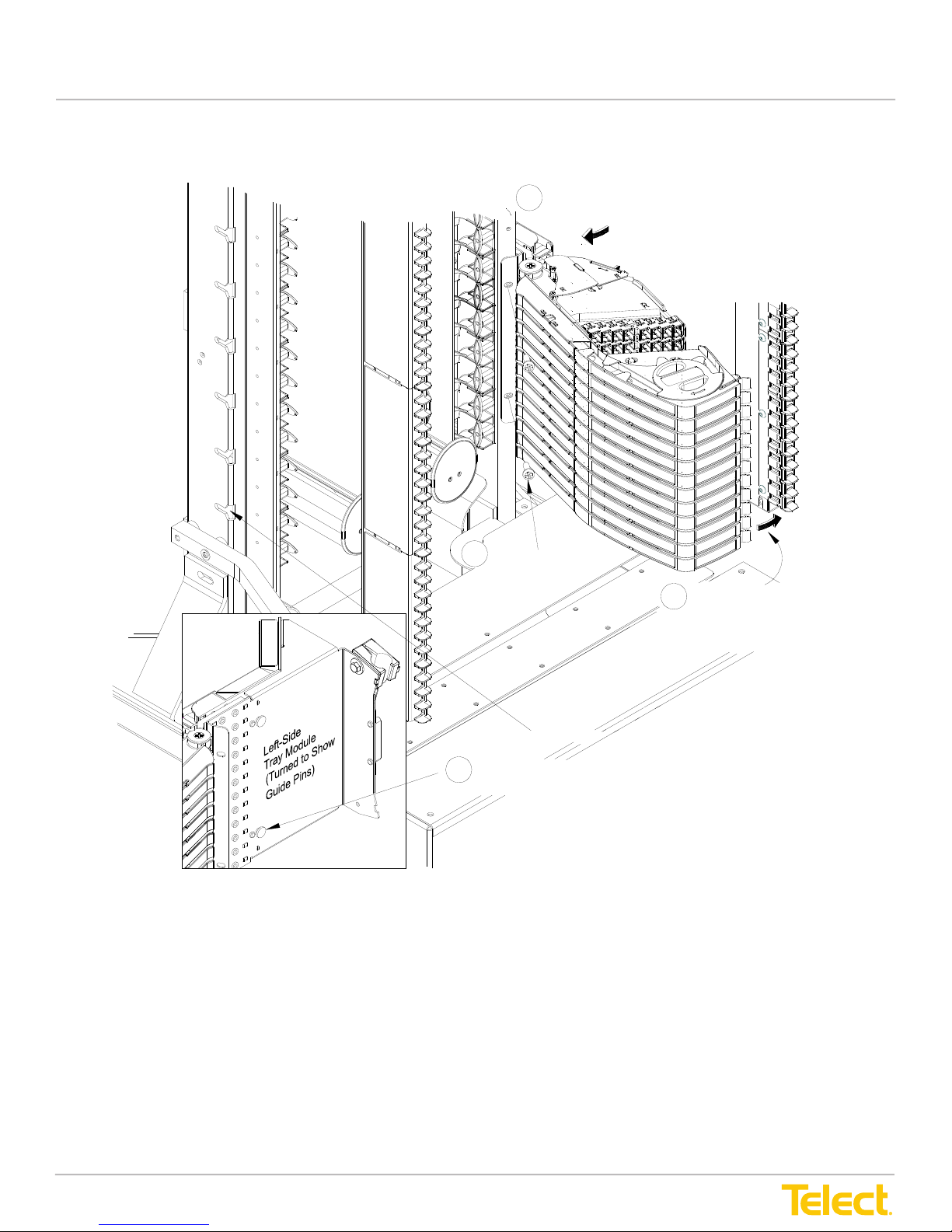
Advanced Distribution Frame (ADF) Systems
c. Fasten with M6 screws near the front. Torque the M6 screws to approximately 5 N•m
.
User Manual
c. Fasten with M6 screws near the front. Torque the M6 screws to approximately 5 N•m.
2a
Pivot Trays Inward About 15°
to Make Installation Easier
M6 Panhead Screws
2c
Secure Module
to ADF
Keyways
Guide Pins on Tray Modules Slip
2b
into Keyways on ADF
2b
Close and latch
trays on latch bar
Figure 36 - Installing a Module on a Main ADF
3. The trays should latch easily. If the trays are not properly aligned, adjust the latch bar as follows:
NOTE: Latch bar adjustment may be necessary only during installation of the rst module (with trays) in a
quadrant. After the rst module with trays is in place, all subsequent modules installed in that quadrant will
align automatically.
a. Make sure all trays are rotated out, away from the latch bar.
b. Loosen the six adjustment screws that hold that latch bar — there are four latch bars, one per quadrant
per Main ADF — to the frame extender. See Figure 37, following:
© Telect, Inc., All Rights Reserved, 12.7.16 v.4
1.509.926.6000 :: telect.com
41
Page 48
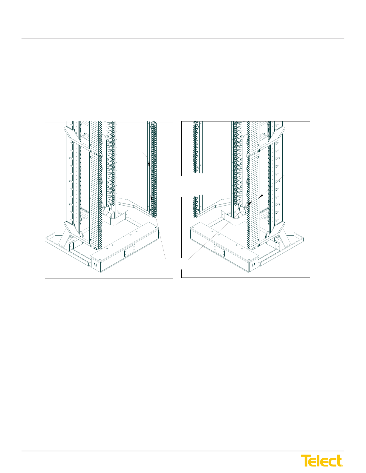
Advanced Distribution Frame (ADF) Systems
c. Move the latch bar up or down so module trays slide smoothly into latch bar.
d. With trays in the latched position, retighten the three outer adjustment screws, then swing
the trays back out, and then finally retighten the three inner screws.
NOTE: For further details on installing an ADF Module to the main frame, please refer to Telect
Part Number 137828, Advanced Distribution Frame Module Installation and Fiber Routing Guide.
You can find this document by searching on the part number or name on Telect.com.
User Manual
c. Move the latch bar up or down so module trays slide smoothly into latch bar.
d. With trays in the latched position, retighten the three outer adjustment screws, then swing the trays
back out and nally retighten the three inner screws.
NOTE: For further details on installing an ADF module to the main frame, please refer to Telect Part Number
137828, Advanced Distribution Frame Module Installation and Fiber Routing Guide. You can nd this document
by searching on the part number or name at Telect.com
Inner
Adjustment
Screws (3)
Outer
Adjustment
Screws (3)
Loosen three inner and
three outer screws to
adjust latch bar
Latch Bar
Figure 37 - Adjusting Latch Bars (ADF Module Not Shown)
Right Corner Front View of Main ADFLeft Corner Front View of Main ADF
© Telect, Inc., All Rights Reserved, 12.7.16 v.4
1.509.926.6000 :: telect.com
42
Page 49
Advanced Distribution Frame (ADF) Systems
User Manual
Chapter 5: Outboard Cabling
WARNING! Fiber cables transmit invisible infrared light. To avoid eye damage or blindness,
never look directly into bers or connectors.
ALERT! Do not stand on utility or ber cable troughs at the base of ADFs.
Outboard cabling deals with installing intrafacility and network element cabling at the rear of the ADF module
– near the rear corners of Main ADF bay. Interconnection and cross-connection via patch cords is done in the
interior area of Main ADF bays, between the right- and left-side ADF modules.
Outboard cabling is covered in detail in the manual accompanying the modules (Telect Part Number 137828,
Module Installation and Fiber Routing Guide). The outboard cabling instructions in this section apply in general
to all intrafacility cable (IFC) and network element (NE) modules.
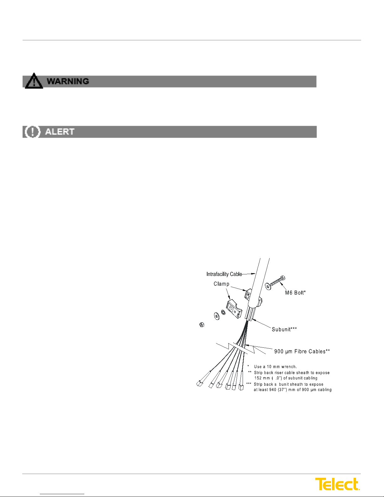
5.1 Intrafacility Cable to Uncabled IFC Module
The intrafacility cable must have at least 37 in. (940
mm) of exposed, connected, 900-µm strands beyond
the jacketed intrafacility cable.
To connect intrafacility cable to an IFC module, refer
to Figures 38 and 39, and proceed as follows:
1. At the rear of the IFC module, attach the jacketed
end of the riser cable to the clamp located at the
rear of the module.
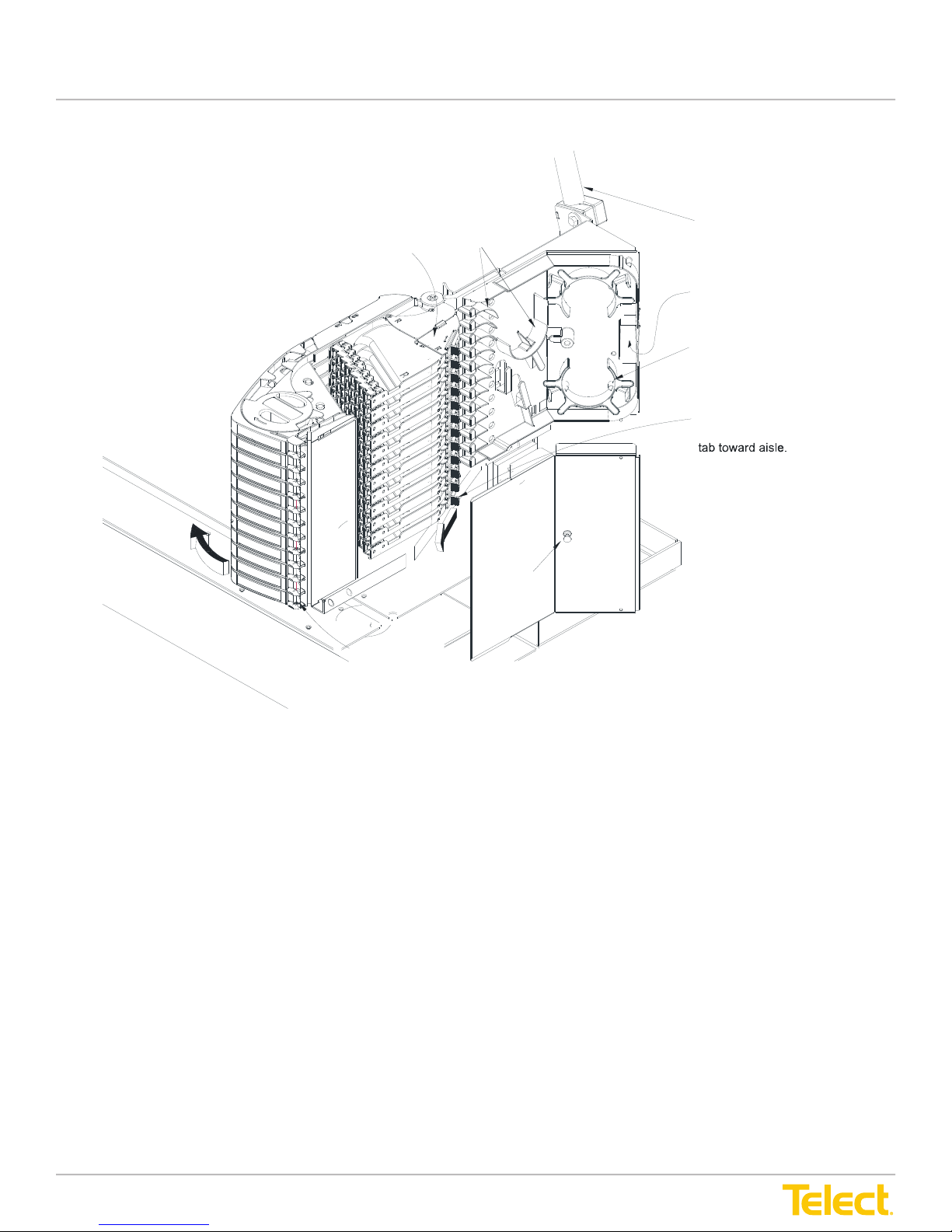
2. Pull the plunger to release and remove the cover
from the breakout area.
4
Figure 38 - Intrafacility Clamp and Cable
© Telect, Inc., All Rights Reserved, 12.7.16 v.4
1.509.926.6000 :: telect.com
43
Page 50
Advanced Distribution Frame (ADF) Systems
Plunger
Lift latch and swing
Open outboard-cabling
access cover by sliding
User Manual
Riser Cable
Outboard-Cabling Access Cover
Guides
Portal to Riser Cable
Storage Spools
Breakout
Box Cover
tray inward before installing cables.
Figure 39 - Riser Cabling to Uncabled IFC Module
3. For the rst tray, open the outboard-cabling access cover by sliding the nger tab toward the front aisle.
© Telect, Inc., All Rights Reserved, 12.7.16 v.4
1.509.926.6000 :: telect.com
44
Page 51
Advanced Distribution Frame (ADF) Systems
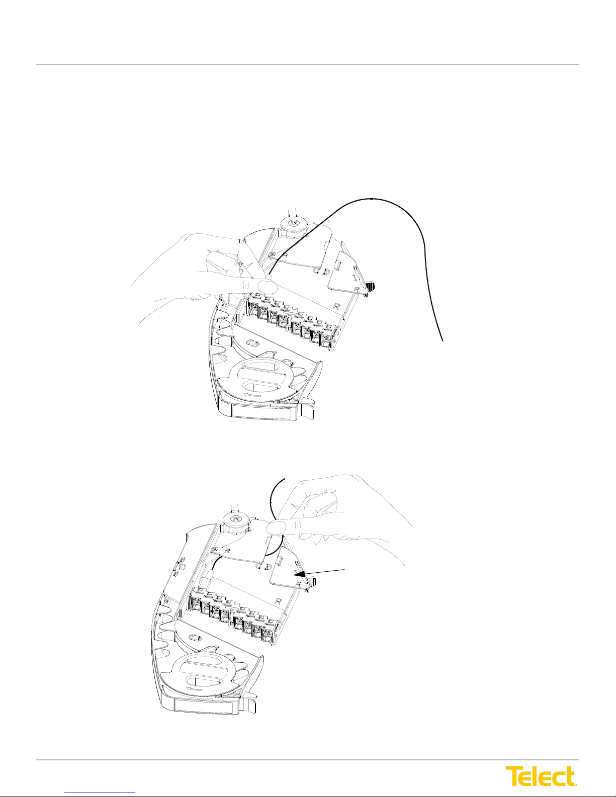
4. As an aid in cabling the first tray, open several or all trays above the first tray. To open trays,
pull slightly on the tray latches and then rotate the trays toward the inboard area of the ADF.
5. Secure the connector of the first 900-µm strand to the adapter.
NOTE: Telect recommends that when installing more than one 900-µm strand in a tray, start with
the adapter closest to the tray’s inboard raceway.
4. As an aid in cabling the first tray, open several or all trays above the first tray. To open trays,
pull slightly on the tray latches and then rotate the trays toward the inboard area of the ADF.
5. Secure the connector of the first 900-µm strand to the adapter.
NOTE: Telect recommends that when installing more than one 900-µm strand in a tray, start with
the adapter closest to the tray’s inboard raceway.
Figure 40 - Securing Connector to Adapter
6. Fit the first strand through the tray’s access cover and route into the breakout area.
User Manual
4. As an aid in cabling the rst tray, open several or all trays above the rst tray. To open trays, pull slightly on
the tray latches and then rotate the trays toward the inboard area of the ADF.
5. Secure the connector of the rst 900-µm strand to the adapter.
NOTE: Telect recommends that when installing more than one 900-µm strand in a tray, start with the adapter
closet to the tray’s inboard raceway.
Figure 40 - Securing Connector to Adapter
6. Fit the rst strand through the tray’s access cover and route into the breakout area.
Outboard Cabling
Access Cover
Figure 41 - Routing Cable to Breakout Area
© Telect, Inc., All Rights Reserved, 12.7.16 v.4
1.509.926.6000 :: telect.com
45
Page 52
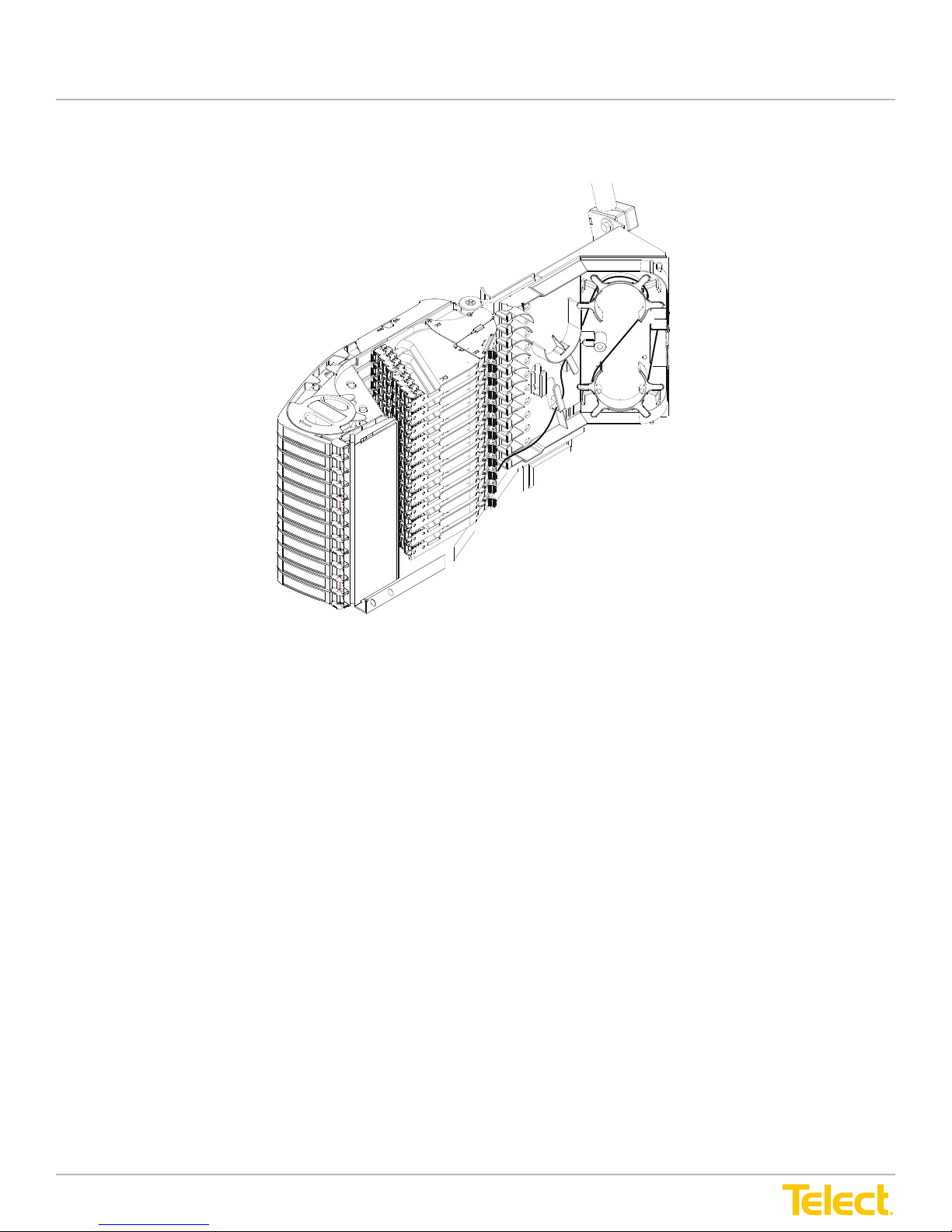
Advanced Distribution Frame (ADF) Systems
7. Carefully fit excess cabling into guides, around storage spools, and out portal, as shown in
Figure 42.
p
r
q
s
User Manual
7. Carefully t excess cabling into guides, around storage spools and out portal, as shown in Figure 42.
o
n
Figure 42 - Excess Cable Routing
8. When nished with one tray, slide closed the outboard cabling access cover shown in Figure 41.
9. Now close the next tray above and repeat Steps 3 through 8 until all 900-µm strands from the riser cable
are installed.
10. When nished with an intrafacility cable, reattach the breakout area cover and swing all applicable trays to
their latched, home (closed) positions.
NOTE: In general, connect and route all outboard 900-µm strands from the riser cables before installing any
inboard patch cords.
© Telect, Inc., All Rights Reserved, 12.7.16 v.4
1.509.926.6000 :: telect.com
46
Page 53
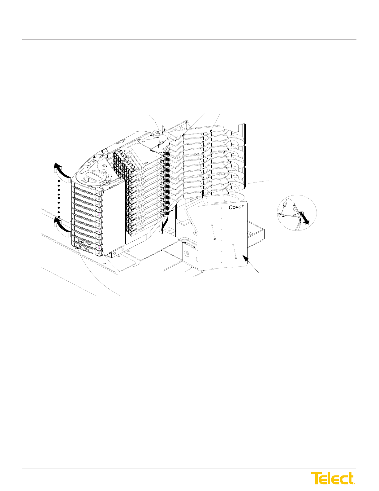
Advanced Distribution Frame (ADF) Systems
5.2 Network Cabling to Network Element Module
To connect network element cabling to a NE module, proceed as follows:
1. Remove the outboard raceway cover (two screws).
Slots for Inserting Cables
User Manual
5.2 Network Cabling to Network Element Module
To connect network element cabling to a NE module, proceed as follows:
1. Remove the outboard raceway cover (two screws).
Outboard-Cabling Access Cover
Open outboard-cabling
access cover by sliding
finger tab toward aisle.
2. As an aid in cabling the rst tray, open several or all trays above the rst tray. (To open trays, pull slightly on
the tray latches and then rotate the trays toward the inboard area of the ADF, as shown in Figure 44, on the
following page.)
3. For the rst tray, open the outboard-cabling access cover by sliding the nger tab toward the front aisle.
Lift latch and swing inward
several or all trays above
the 1st tray to be cabled.
Keep the 1st tray for cabling
latched in its closed position.
Cover Over Channels
of Outboard Raceway
Figure 43 - Network Element Cabling (Example)
© Telect, Inc., All Rights Reserved, 12.7.16 v.4
1.509.926.6000 :: telect.com
47
Page 54
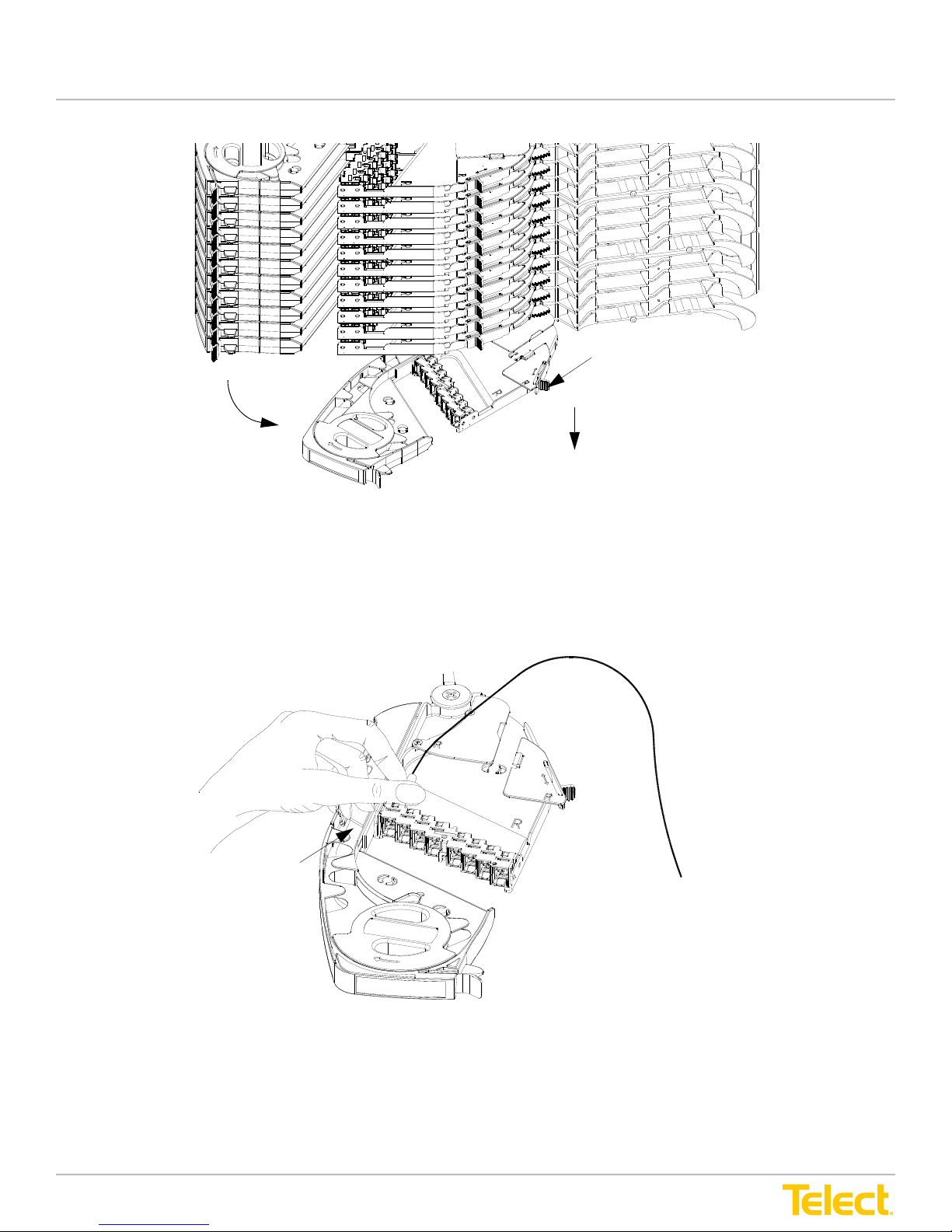
Advanced Distribution Frame (ADF) Systems
Opened Trays
Closed Tray
Finger Tab
Figure 44 - Opening Trays
4. Secure the connector on the network element cable to the adapter.
NOTE: Telect recommends that, when installing more than one network element cable in a tray,
you start with the adapter closest to the tray’s inboard raceway.
User Manual
Finger Tab
Opened Trays
Closed Tray
Figure 44 - Opening Trays
4. Secure the connector on the network element cable to the adapter.
NOTE: Telect recommends when installing more than one network element cable in a tray, you start with the
adapter closest to the tray’s inboard raceway.
Inboard Raceway
Figure 45 - Securing Connector to Adapter
© Telect, Inc., All Rights Reserved, 12.7.16 v.4
1.509.926.6000 :: telect.com
48
Page 55
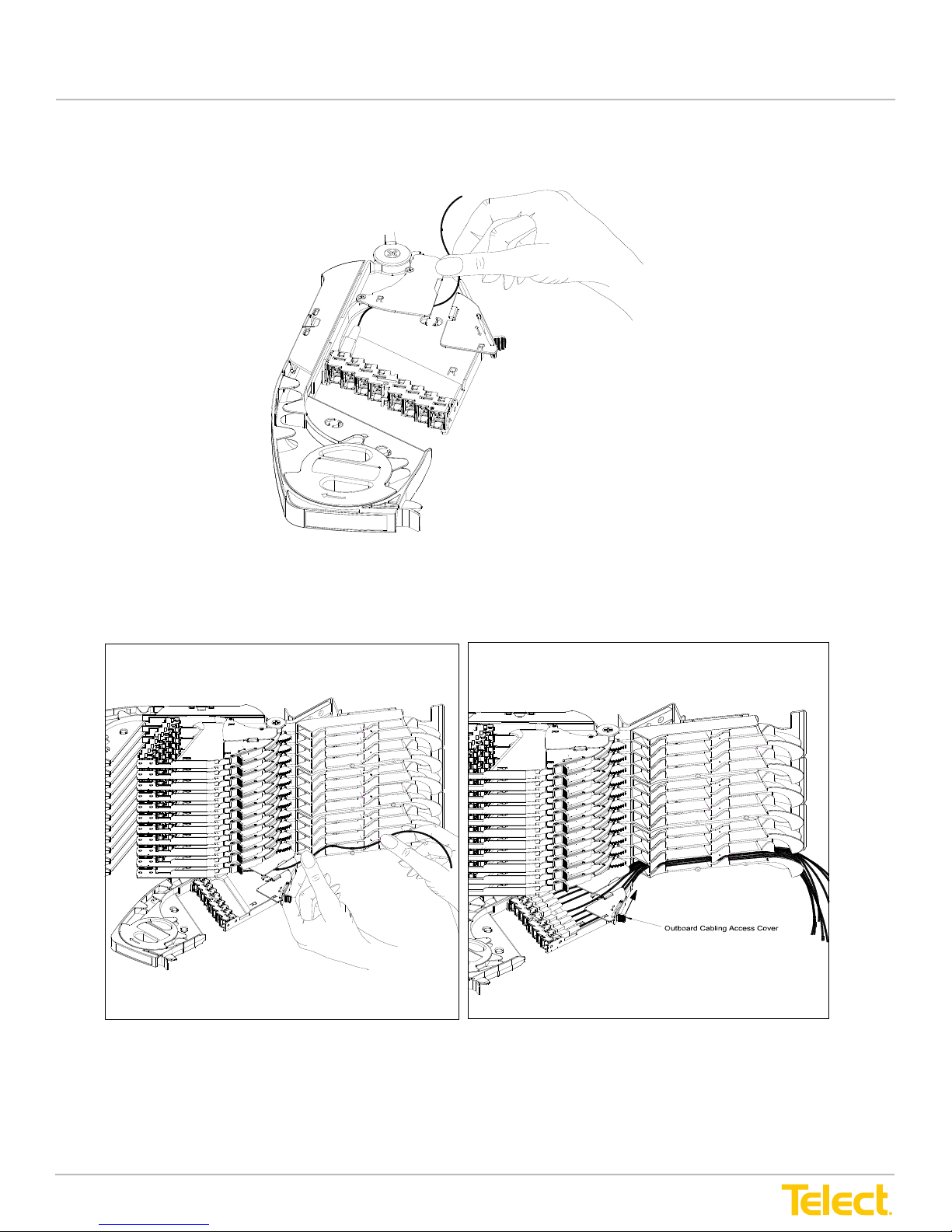
Advanced Distribution Frame (ADF) Systems
5. Fit the first cable through the tray’s access cover and route into the channel.
5. Fit the first cable through the tray’s access cover and route into the channel.
Figure 46 - Routing Cable to Channel
6. Route the cable through the channel and then cascade at the rear of the module, as shown in
Figure 47.
User Manual
5. Fit the rst cable through the tray’s access cover and route into the channel.
Figure 46 - Routing Cable to Channel
6. Route the cable through the channel and then cascade at the rear of the module, as shown in Figure 47.
Figure 47 - Cable Routing through Channel to Rear of Module
7. When nished with the rst tray, slide the outboard cabling access cover closed.
8. Now close the next tray above and repeat Steps 3 through 7 for the next cable.
© Telect, Inc., All Rights Reserved, 12.7.16 v.4
1.509.926.6000 :: telect.com
49
Page 56

Advanced Distribution Frame (ADF) Systems
User Manual
9. Route the rest of the network element cabling for that module before reattaching the outboard
raceway cover.
NOTE: In general, connect and route all outboard network element cables before installing any inboard
patch cords.
© Telect, Inc., All Rights Reserved, 12.7.16 v.4
1.509.926.6000 :: telect.com
50
Page 57
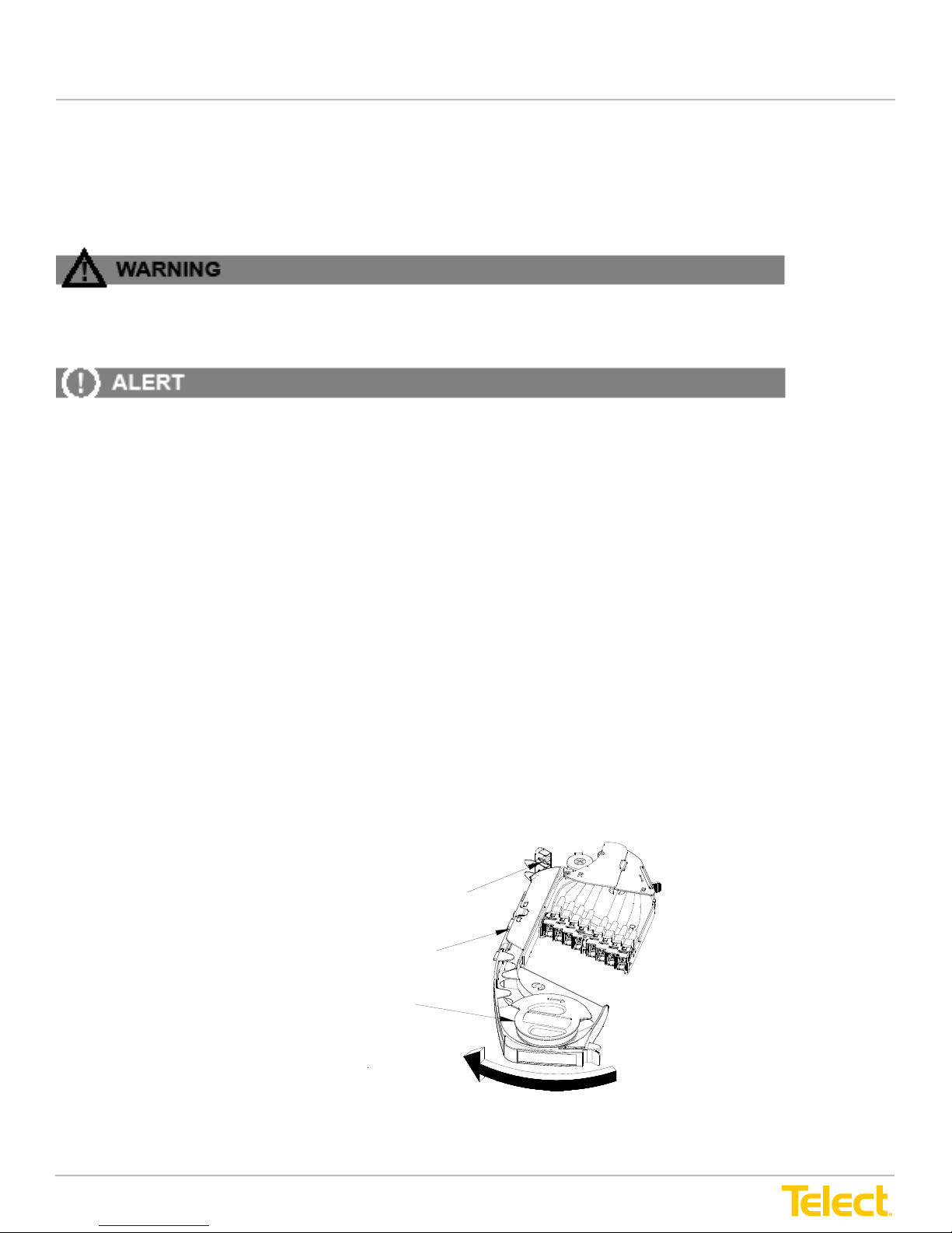
Advanced Distribution Frame (ADF) Systems
Chapter 6: Inboard Cabling
Advanced Distribution Frame (ADF) Systems
Inboard cabling involves interconnecting riser cables to network elements using patch cords on
the inboard side of ADF modules, and cross-connecting network element cables using patch
cords on the inboard side of ADF modules.
WARNING
!
WARNING! Fiber cables transmit invisible infrared light. To avoid eye damage or blind-
ness, never look directly into fibers or connectors.
ALERT
ALERT! Do not stand on utility or fiber cable troughs at the base of ADFs.
6.1 Installing Inboard Cabling
In the following procedure, two important points need to be emphasized:
1. ALWAYS make end connections first and then route cable in troughs, around spools, etc.,
between those terminations. With Telect’s ADF, there is no need to fish cables before
making termination connections.
2. ALWAYS route cables very loosely. Leave plenty of slack, especially at or near transition
and same-side spools. As more and more cables are added to a cabling scenario, the
newly routed cables tend to weigh down the previously routed cables, with the tendency
to pull down on the vertical cable runs on both sides of the spools.
Proceed as follows to install interconnect or cross-connect cabling:
Procedure steps:
1. Work with one network element (NE) cable or patch cord at a time. Prepare tray(s) for cabling
at both cable ends.
User Manual
Chapter 6: Inboard Cabling
Inboard cabling involves interconnecting riser cables to network elements using patch cords on the inboard
side of ADF modules and cross-connecting network element cables using patch cords on the inboard side of
the ADF modules.
WARNING! Fiber cables transmit invisible infrared light. To avoid eye damage or blindness,
never look directly into bers or connectors.
ALERT! Do not stand on utility or ber cable troughs at the base of ADFs.
6.1 Installing Inboard Cabling
In the following procedure, two important points need to be emphasized:
1. ALWAYS make end connections rst and then route cable in troughs, around spools, etc., between those
terminations. With the Telect ADF, there is no need to sh cables before making termination connections.
2. ALWAYS route cables very loosely. Leave plenty of slack, especially at or near transition and same-side
spools. As more and more cables are added to a cabling scenario, the newly routed cables tend to weigh
down the previously routed cables, with the tendency to pull down on the vertical cable runs on both sides
of the spools.
Proceed as follows to install interconnect or cross-connecting cabling:
Procedure steps:
1. Work with one network element (NE) cable or patch cord at a time. Prepare tray(s) for cabling at both
cable ends.
d) Switch Turnstile Open
c) Snap Open Door
b) Rotate Spool
a) Swing Open Tray
Figure 48 - Cable Preparation
© Telect, Inc., All Rights Reserved, 12.7.16 v.4
1.509.926.6000 :: telect.com
51
Page 58
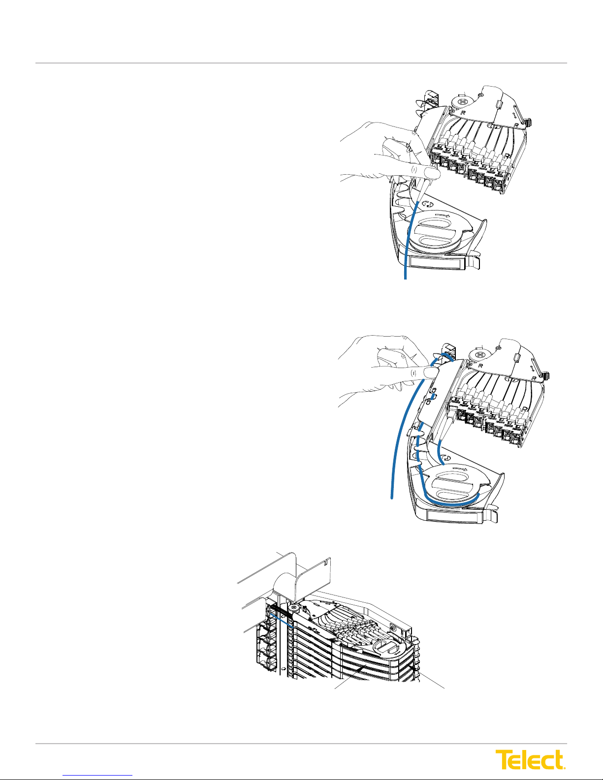
Advanced Distribution Frame (ADF) Systems
Figure 49 - Connecting Patch Cord
Figure 49 - Connecting Patch Cord
Figure 50 - Cable Routing in Tray
Tr ay L
Españo
Español :
6
Interconnection / Cross-Connection
Label
User Manual
2. Connect the patch cord to the adapter(s). Remember,
when cross-connecting, connect the patch cord at
both ends before routing cable.
Figure 49 - Connecting Patch Cord
3. Fit the cable neatly around the spool, through the
raceway, then into the cascade.
4. Close spool(s), door(s), turnstile(s) and then tray(s).
5. Record termination information on labels.
6. Place the cable run in
troughs, channels and other
cable management system
components before routing
cable around ADF spools.
© Telect, Inc., All Rights Reserved, 12.7.16 v.4
1.509.926.6000 :: telect.com
Figure 50 - Cable Routing in Tray
Interconnection Label
Figure 51 - Cable Routing in Module
52
Tray Label
Page 59
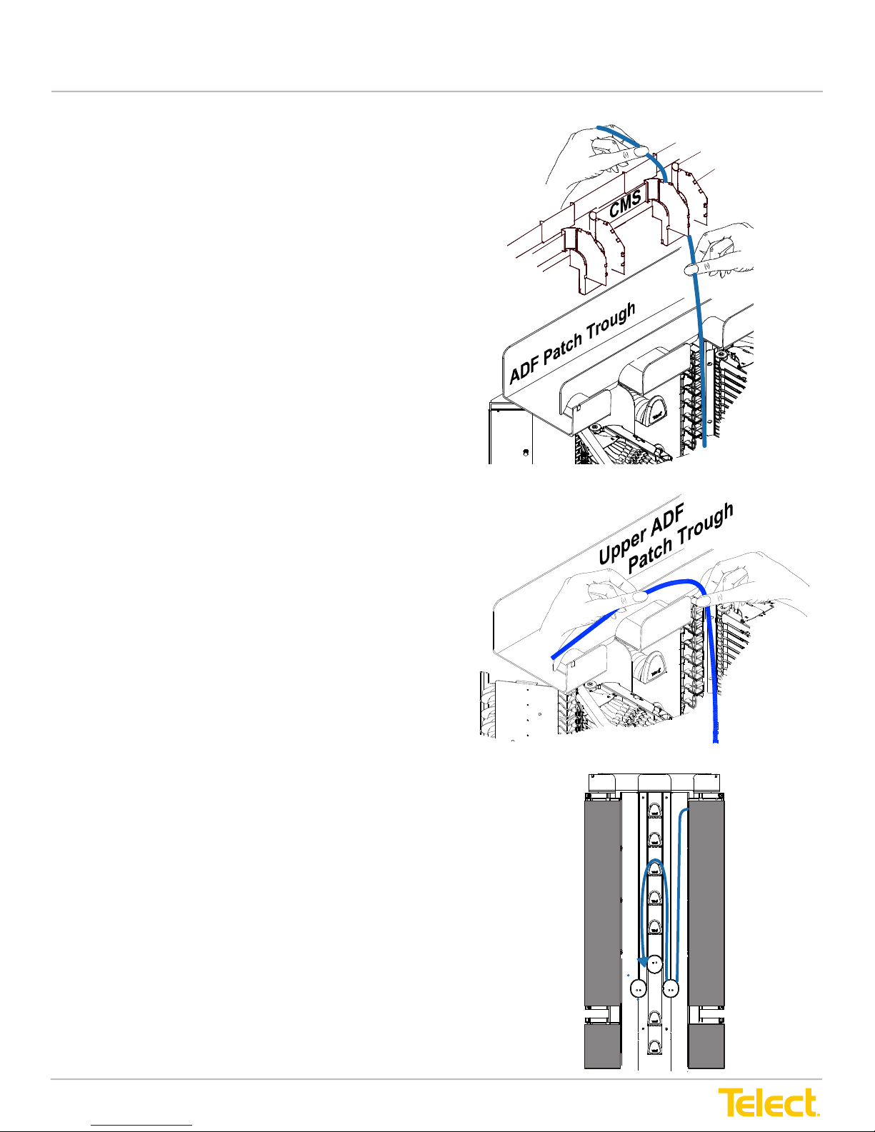
Advanced Distribution Frame (ADF) Systems
Español: 1.
Figure 52 - Interconnecting
Cable Routing
Español: 1.
User Manual
If interconnecting, route cable through the cable
management system (CMS) to the CMS drop above ADF,
as shown in Figure 52.
If cross-connecting between Main ADFs, place the
patch cord in the upper or lower ADF patch trough(s)
between the ADF frames, as shown in Figure 53.
7. Route the cable down from the cascade along the nearest side of the
nearest transition. Start by routing cable around the transition spool
and then up and around the convenient storage and transition spools.
NOTE: Which sets of spools you use in routing will depend on 1) your
interconnect or cross-connect application and 2) your cable storage
requirements. (See “Applications” on page 19 for more information
about applications.)
Figure 52 - Interconnecting Cable Routing
Figure 53 - Cross-Connecting Cable Routing
8. Store excess cable on the Main ADFs and/or one or more Interbay
Storage Panels.
This procedure is complete.
Figure 54 - Cable Routing Down Cascade
© Telect, Inc., All Rights Reserved, 12.7.16 v.4
1.509.926.6000 :: telect.com
53
Page 60
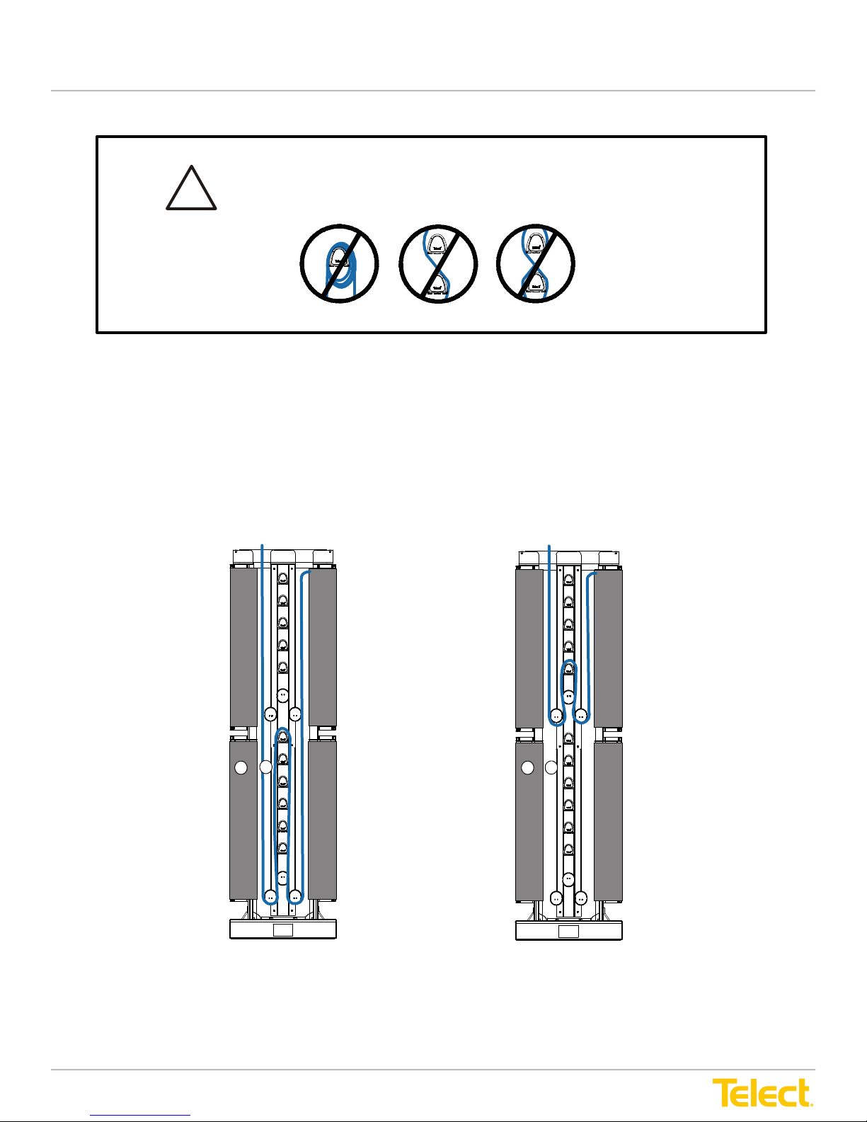
Advanced Distribution Frame (ADF) Systems
To minimize signal attenuation, make the least number of switchbacks as
possible when routing fiber cable. NEVER WRAP, WEAVE, CRISSCROSS,
OR“FIGURE 8” THE FIBER CABLES.
!
6.2 Routing & Storing Inboard Cabling
6.2.1 Interconnection
The following figures show various routing methods involving overhead interconnection cabling
to a tray. Typical interconnections are between network elements or between a network element
and either intrafacility cable (IFC) or outside plant (OSP) cable.
User Manual
To minimize signal attenuation, make the least number of switchbacks as
possible when routing fiber cable. NEVER WRAP, WEAVE, CRISSCROSS,
!
OR“FIGURE 8” THE FIBER CABLES.
6.2 Routing & Storing Inboard Cabling
6.2.1 Interconnection
The following gures show various routing methods involving overhead interconnection cabling to a tray.
Typical interconnections are between network elements or between a network element and either intrafacility
cable (IFC) or outside plant (OSP) cable.
Figure 55 - Interconnection within a Single Frame
© Telect, Inc., All Rights Reserved, 12.7.16 v.4
1.509.926.6000 :: telect.com
54
Page 61
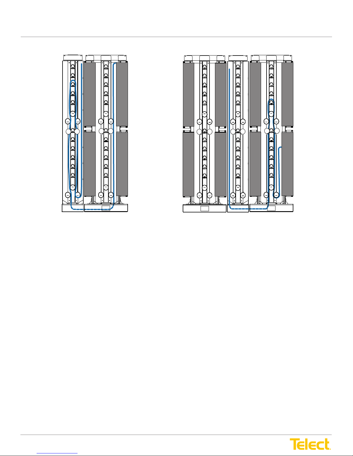
Advanced Distribution Frame (ADF) Systems
User Manual
Figure 56 - Interconnection with Storage on ISP
© Telect, Inc., All Rights Reserved, 12.7.16 v.4
1.509.926.6000 :: telect.com
55
Page 62
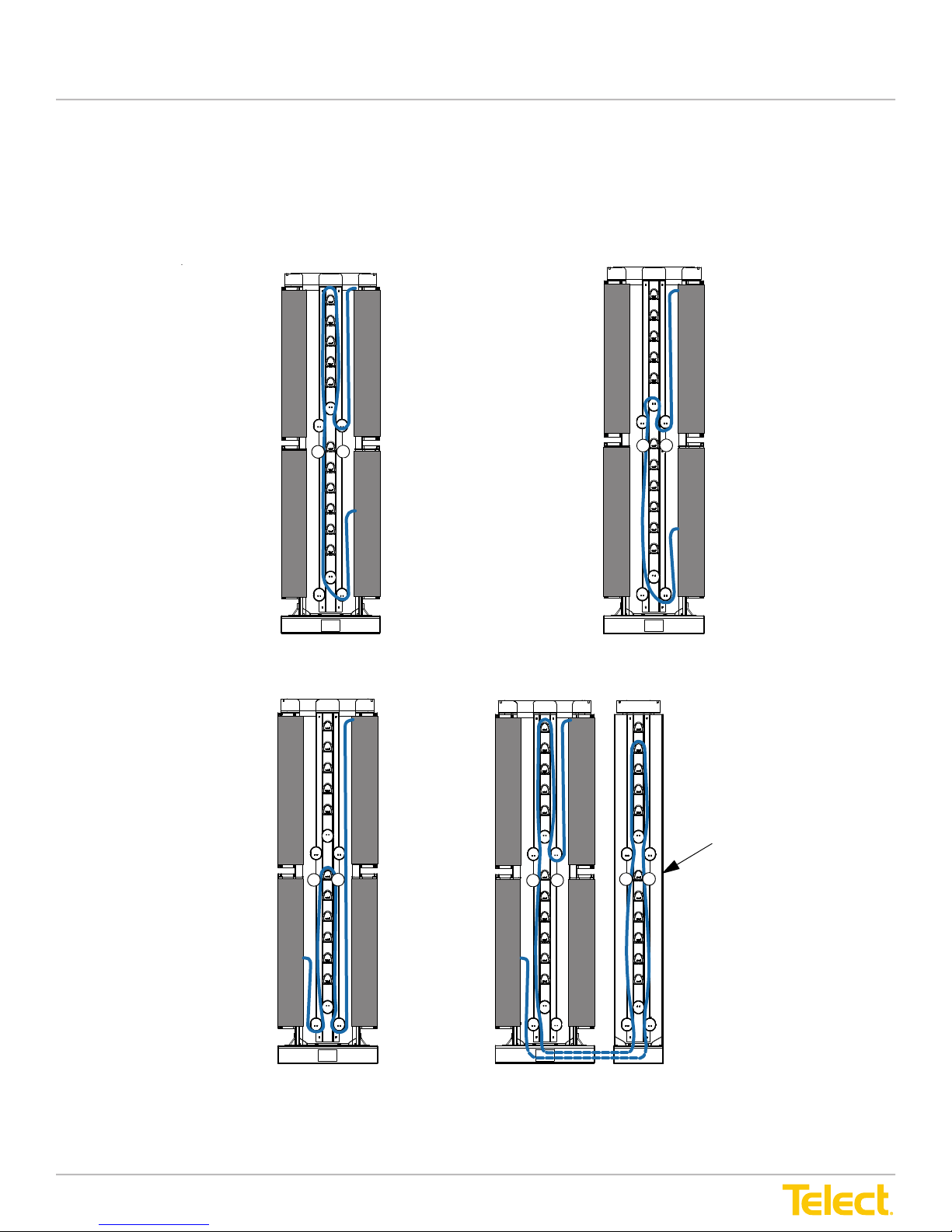
Advanced Distribution Frame (ADF) Systems
Figure 57 - Patching to Same Side of Same ADF
User Manual
6.2.2 Cross-Connection
The examples that follow show various routing methods involving cross-connection patch cabling between
trays on the same or different Main ADFs. Typical interconnections are between network elements, between
a network element and either intrafacility cable (IFC) or outside plant (OSP) cable, or between IFC and/or
OSP cables.
Figure 57 - Patching to Same Side of Same ADF
Figure 58 - Patching to Opposite Side of Same ADF
Storage on an
InterBay
© Telect, Inc., All Rights Reserved, 12.7.16 v.4
1.509.926.6000 :: telect.com
56
Page 63
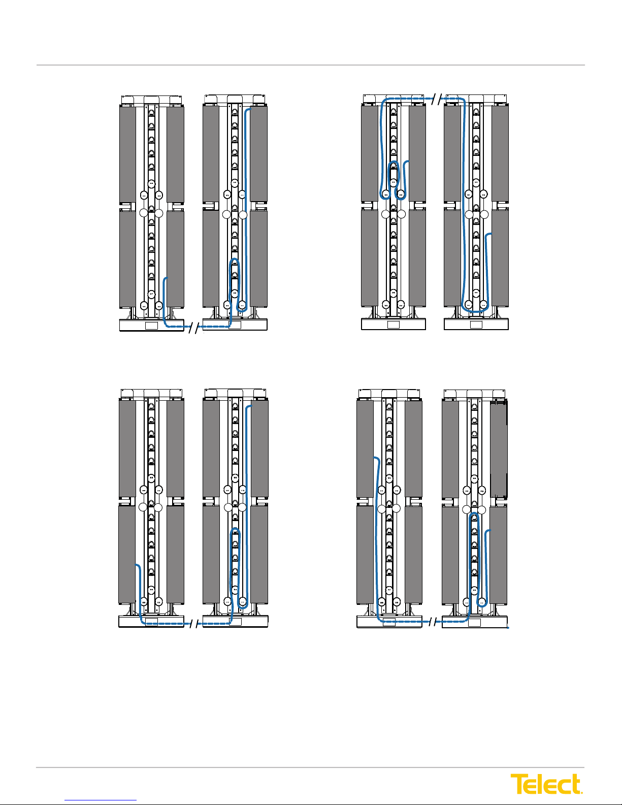
Advanced Distribution Frame (ADF) Systems
Figure 59 - Patching to Same Side of Different ADFs
User Manual
Figure 59 - Patching to Same Side of Different ADFs
Figure 60 - Patching to Opposite Side of Different ADFs (without ISP)
© Telect, Inc., All Rights Reserved, 12.7.16 v.4
1.509.926.6000 :: telect.com
57
Page 64
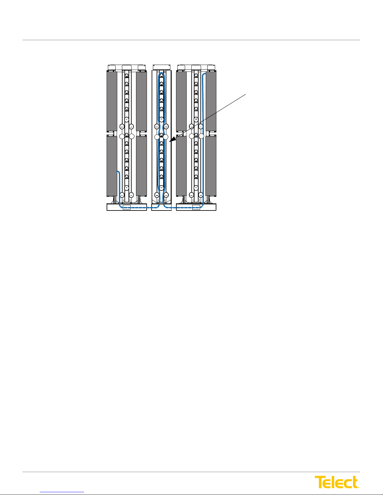
Advanced Distribution Frame (ADF) Systems
User Manual
Storage on an
InterBay
Figure 61 - Patching to Opposite Side of Different ADFs (with ISP)
© Telect, Inc., All Rights Reserved, 12.7.16 v.4
1.509.926.6000 :: telect.com
58
Page 65

Advanced Distribution Frame (ADF) Systems
User Manual
Chapter 7: Service
7.1 Owner Maintenance
The Telect Main ADFs and Interbay Storage Panels need no preventitive maintenance.
7.2 Technical Support
By e-mail: [email protected]
By phone: 509-962-6000
7.3 In-Warranty Service
Contact your Telect equipment distributor or call Telect at 509-926-6000.
Telect will repair or replace defective products within the limits of the warranty. See “Repacking for Shipment”
in this section.
NOTE: Call a Customer Service Representative for a Return Material Authorization (RMA) before returning
any equipment.
7.4 Out-of-Warranty Service
The procedure for out-of-warranty service is the same as for in-warranty service, except that Telect charges a
processing fee and you must submit a Purchase Order along with a Return Material Authorization (RMA)
before returning equipment. Call Telect at 509-926-6000 for assistance in obtaining these forms. The
processing fee guarantees a repair estimate and is credited against actual material and labor costs.
7.5 Repacking for Shipment
1. Tag the equipment showing owner’s name, address and telephone number together with a detailed
description of the problem.
2. Use the original shipping container if possible. If you do not have it, package the equipment in a way to
prevent shipping damage. Include the RMA inside the container and legibly print the RMA number on the
outside of the package, near the shipping address.
3. Insure the package.
NOTE: Telect is not liable for shipping damage.
© Telect, Inc., All Rights Reserved, 12.7.16 v.4
1.509.926.6000 :: telect.com
59
Page 66

Advanced Distribution Frame (ADF) Systems
User Manual
This page intentionally left blank.
© Telect, Inc., All Rights Reserved, 12.7.16 v.4
1.509.926.6000 :: telect.com
60
Page 67

Advanced Distribution Frame (ADF) Systems
User Manual
Chapter 8: Bays and Accessories
Part Number Description
ADF Frames
ADF-26F-XI ADF 26" W x 24" D Standard XI Frame
ADF-600F ADF 600 mm W x 600 mm D Standard XI Frame
ADF Floor Anchors
ADF-26ANCHOR Concrete Floor Anchors for ADF-26F Frame (Seismic Rated)
ADF-26COMPFLR Raised Floor Anchors for ADF-26F Frame
ADF-600ANCHOR Concrete Floor Anchors for ADF-600F Frame (Seismic Rated)
ADF-600COMPFLR Raised Floor Anchors for ADF-600F Frame
ADF-12ANCHOR Concrete Floor Anchors for ADF-12INT Interbay Storage Panel (Seismic Rated)
ADF-12COMPFLR Raised Floor Anchors for ADF-12INT Interbay Storage Panel
ADF-300ANCHOR Concrete Floor Anchors for ADF-300INT Interbay Storage Panel (Seismic Rated)
ADF-300COMPFLR Raised Floor Anchors for ADF-300INT Interbay Storage Panel
Interbay Storage Panels
ADF-12INT 12" Wide Interbay Storage Panel Standard
ADF-300INT-XI 300 mm Wide Interbay Storage Panel Standard
End Panels
ADF-26EP 5" Wide End Panel for ADF-26F and ADF-12INT
ADF-26EP-2 2" Wide End Panel for ADF-26F and ADF-12INT
ADF-300EP 2" Wide End Panel for ADF-600F and ADF-300INT
Isolation Pads
ADF-26F-ISOPAD ADF-26F and ADF-26F-I Frame Isolation Pad
ADF-12INT-ISOPAD ADF-12INT Interbay Storage Panel Isolation Pad
ADF-26EP-5-ISOPAD ADF 5" Wide End Panel Isolation Pad
ADF-26EP-2-ISOPAD ADF 2" Wide End Panel Isolation Pad
ADF-600F-ISOPAD ADF-600F Frame Isolation Pad
ADF-300F-ISOPAD ADF-300F Interbay Storage Panel Frame Isolation Pad
ADF-300EP-ISOPAD ADF ETSI End Panel Isolation Pad
Grounding
301597 ADF Ground Wire
Go to Telect.com for additional information regarding intrafacility, network element or fan-out modules.
© Telect, Inc., All Rights Reserved, 12.7.16 v.4
1.509.926.6000 :: telect.com
61
 Loading...