

Page 1
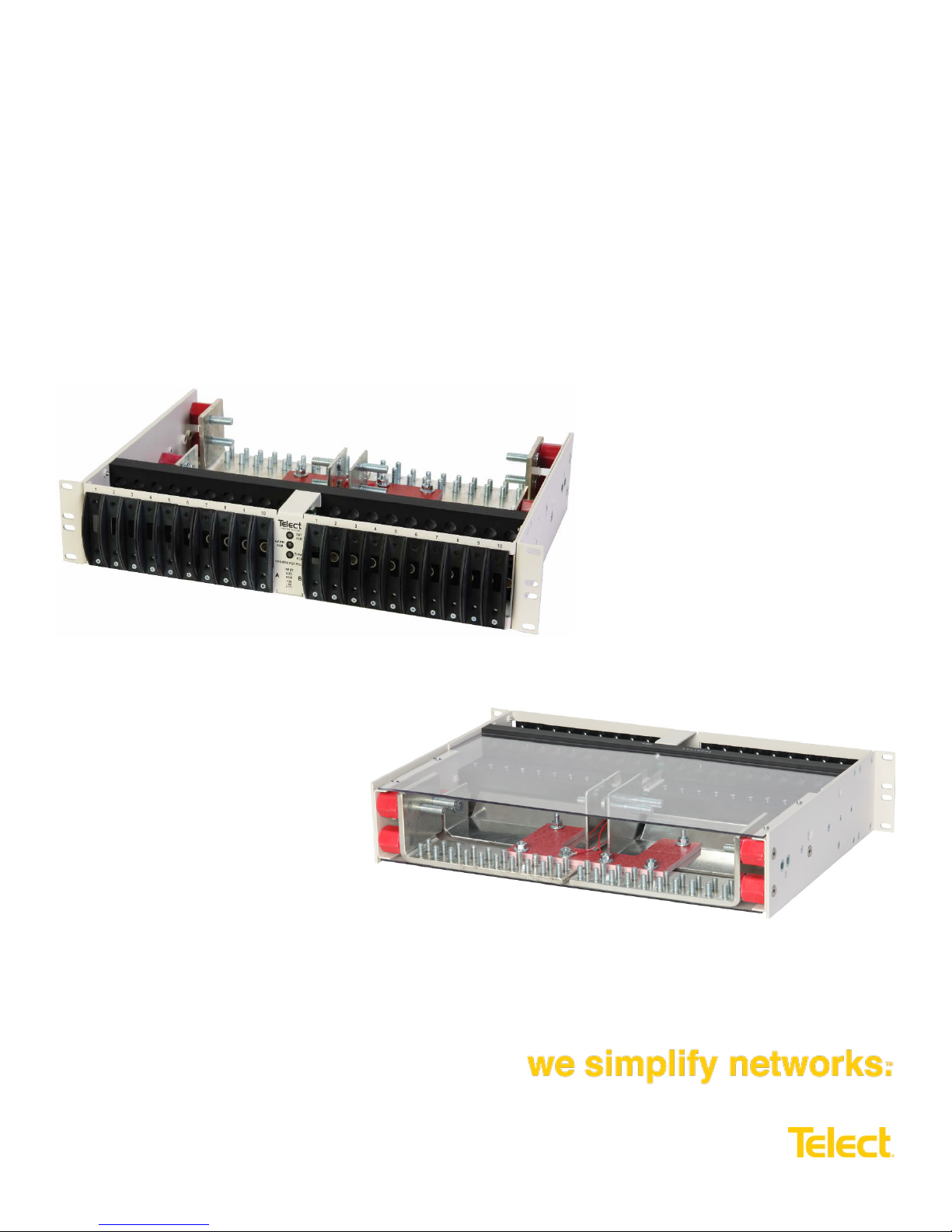
Dual-Feed 600A Load
Center Frame
600CB10 & 600CB1 2 Installation Gui de
600CB10 – Front View
600CB10-C – Rear View
Page 2

Dual-Feed 600A Load Center Frame
600CB10 & 600CB12 Installation Guide
Installation Guide Part Number, 136429-2
Applies to: 600CB10 :: 600CB10-C :: 600CB10-VL :: 600CB10-CL :: 600CB12 :: 600CB12-C ::
600CB12-VL :: 600CB12-CL
Copyright 2017, Telect, Inc., All Rights Reserved
Telect and Connecting the Future are registered trademarks of Telect, Inc.
22425 #11 East Appleway Ave.
Liberty Lake, WA 99019
Telect assumes no liability from the application or use of these products. Neither does Telect convey any license under its
patent rights nor the patent rights of others. This document and the products described herein are subject to change
without notice.
Connecting the future for over 30 years
Telect challenges the status quo and looks beyond what is possible in network connectivity and power management.
Founded in 1982, Telect is driven by the principles of innovation and customer service. Headquartered in Liberty
Lake, WA, the privately held company supports a global network of customers with a comprehensive product
portfolio and a values-driven corporate culture.
Our products and solutions are found across communications service-provider networks, data centers and utility
networks around the globe.
At Telect, we pride ourselves on our ability to respond to customer challenges, building a reputation among
communications service providers for delivering solutions uniquely tailored to their needs.
We simplify networks.™
• Custom configured solutions
• Products integrate seamlessly into existing infrastructure
• Exceptional customer service
• Hassle-free warranty
Technical Support
Email: [email protected]
Phone: 509-926-6000
© Telect, Inc. All rights reserved. 7.14.17 136429-2
509.926.6000 :: www.telect.com
I
Page 3

Dual-Feed 600A Load Center Frame
600CB10 & 600CB12 Installation Guide
Table of Contents
1.1 Overview ........................................................................................................................................................................... 1
1.2 Installation Guidelines ....................................................................................................................................................... 2
1.3 Specifications .................................................................................................................................................................... 2
1.4 Installation Instructions ...................................................................................................................................................... 4
1.5 Parts & Accessories ........................................................................................................................................................ 13
1.6 Interconnections .............................................................................................................................................................. 15
1.7 Drawings ......................................................................................................................................................................... 16
List of Figures
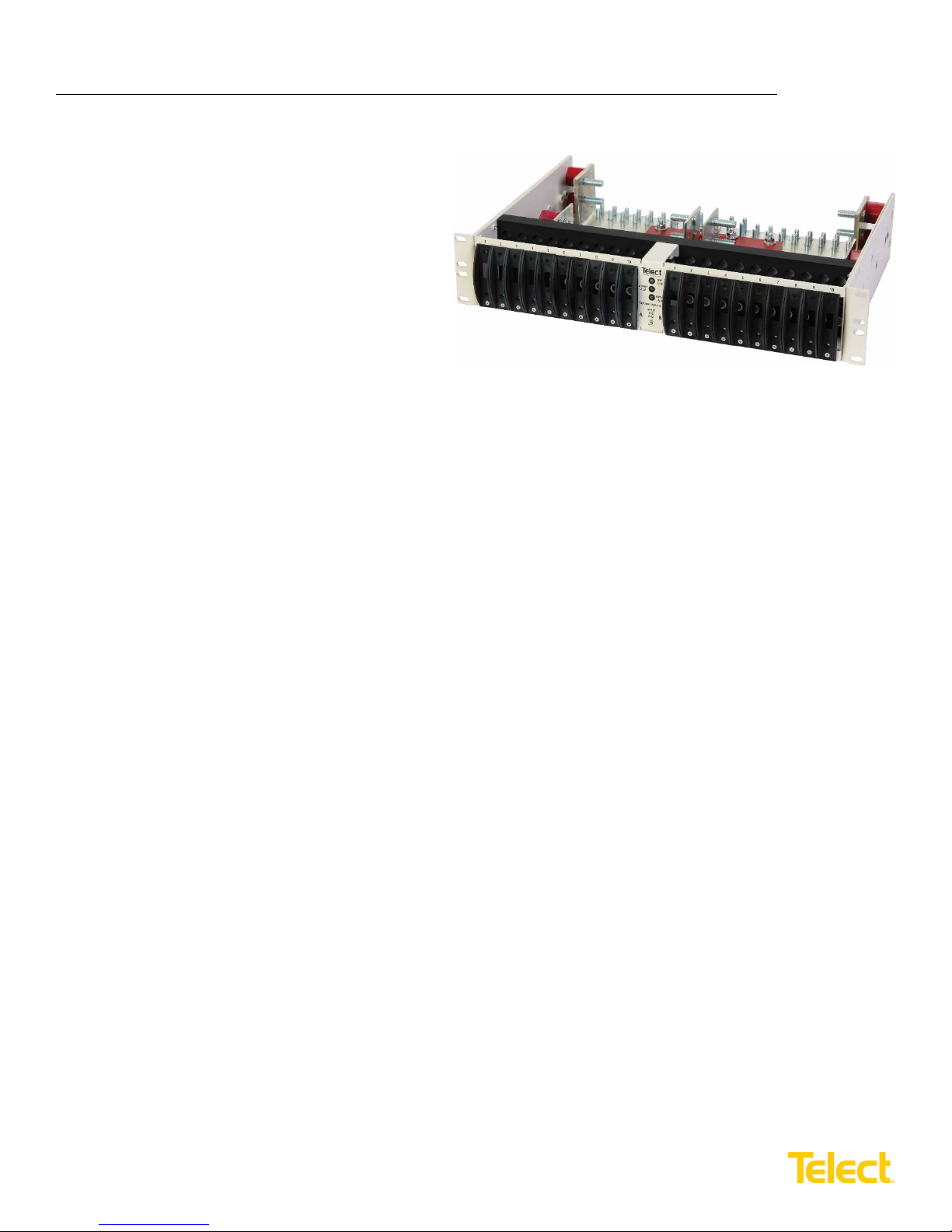
Figure 1 – 600CB10, 19" 10/10 Position Load Center Frame ................................................................................................ 1
Figure 2 – Installing Load Straps ............................................................................................................................................ 5
Figure 3 – Alarm Board Location (Bottom View of Side A) ..................................................................................................... 5
Figure 4 – Alarm Board Jumper Settings ................................................................................................................................ 6
Figure 5 – Alarm Wiring .......................................................................................................................................................... 6
Figure 6 – Rack Mounting ....................................................................................................................................................... 7
Figure 7 – Ground Lug Connection ......................................................................................................................................... 8
Figure 8 – Input Lugs .............................................................................................................................................................. 9
Figure 10 – Output Lug Connections .................................................................................................................................... 10
Figure 11 – Installing Circuit Breakers .................................................................................................................................. 11
Figure 12 – Installing Fuse Holders and Fuses .................................................................................................................... 11
© Telect, Inc. All rights reserved. 7.14.17 136429-2
509.926.6000 :: www.telect.com
II
Page 4
Dual-Feed 600A Load Center Frame
Load Center Frame
600CB10 & 600CB12 Installation Guide
1.1 Overview
The Telect dual-feed 600A per feed load center frames
provide high-capacity, -48V and ±24V power protection
for secondary power distribution and data, and
communications equipment. Telect load center frames
are also ideal for primary distribution in small central
offices and at remote sites.
Models 600CB10 and 600CB12 are open-frame
chassis providing excellent heat diss ip ati on and
overhead access to the load center’s BATT and RTN
terminals, vertical inputs.
Models 600CB10 and 600CB12 are white, 2RU, and fit
racks with either EIA or WECO spacing.
• Model 600CB10 contains 10 interrupter positions
on each side and fits a 19-in. rack (an adapter
kit can be purchased separately to mount the
600CB10 in a 23" rack).
• Model 600CB12 has 12 interrupter positions on
each side and fits a 23-in. rack.
Both accommodate AIRPAX
through quad-pole configurations. Each circuit breaker or fuse pole position accommodates a bullet-style, plug-in circuit
breaker or fuse holder up to 100A. With double-pole circuit breakers or TPW fuses, the maximum output load can be up to
200A. The triple-pole circuit breakers have a maximum load of 250A and the quad-pole circuit break ers have a maximum
load of 400A.
Sides A and B are electrically isolated except for the alarm card, which contains power, fuse and bay status relays with
dry, Form-C contacts. The contacts are connected to wire-wrap pins to switch on external power to visual/audio external
alarms. The alarm card also controls the three dual-color LEDs on the front panel.
All input, output and alarm terminals are within the open-frame chassis. All BATT and RTN inputs, outputs and ground
accommodate dual-hole lugs. Input and output terminals are studs and the ground terminals are bolt connections at the
sides of the load center near the rear corners. Only one ground connection is required.
®
-style LEL or Carling CA1 circuit breakers or fuses (TPC/TPW and TPS/TLS) in single-
Figure 1 – 600CB10, 19" 10/10 Position
Fuses, fuse holders and circuit breakers are sold separately. Also sold separately are single-, doubl e-, triple- and quadpole straps for the output of the breakers or fuses. These copper straps bridge the output of the fuse holders or circuit
breakers to the output studs. See telect.com to order breakers, fuses, fuse holders and load straps.
The 600CB10-C and 600CB12-C provide horizontal inputs and a cover. The 600CB10-CL and 600CB12-CL also provide
horizontal inputs, a cover and single-pole load straps pre-installed into the panel.
The 600CB10-VL and 600CB12-VL provide vertical inputs as well as single-pole load straps pre-installed into the panel.
© Telect, Inc. All rights reserved. 7.14.17 136429-2
509.926.6000 :: www.telect.com
1
Page 5
Dual-Feed 600A Load Center Frame
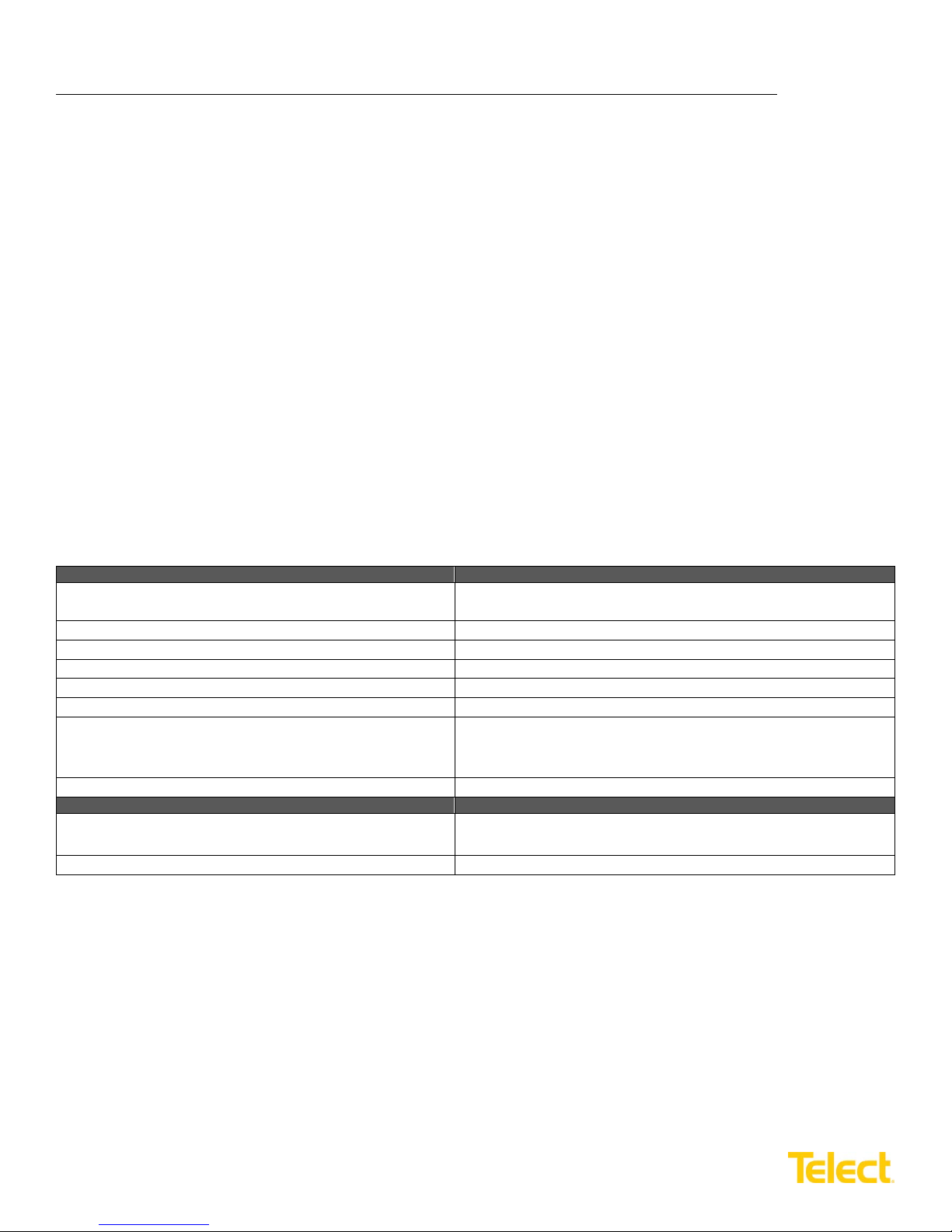
Inputs:
Specifications:
Voltage range (nominal voltage)
±21.6V to ±30V (nominal ±24 VDC)
-40V to -60V (nominal -48 VDC)
Max. input load rating
600A per side at max. operating ambient of 49°C (120°F)
Short circuit withstand rating
5000A
Nominal power loss at full load
Less than 75W per side @ 28,800W full load per side (600A x 48V)
Percentage of full power dissipation at nominal voltage
Less than 1%
Max. input interrupt device
750A
Input terminal studs (with nuts, flat washers and spring
Two pairs of
3
/
-16 studs on 1-in. centers per terminal [max. lug
mm wrench) to 150-in./lb. (~17 N•m), max.
Input wire size
#1 AWG to 750 MCM
Grounding:
Specifications:
Earth GND terminal bolts (with washers) for dual-hole
Two pair of
1
/
-20 threaded holes on
5
/
-in. centers. Torque bolts
Ground wire size
#2 AWG (min.) for any input interrupt device 400A or more
600CB10 & 600CB12 Installation Guide
1.2 Installation Guidelines
Elevated Operating Ambient – If installed in a closed or multi-unit rack assembly, the operating ambient temperature of
the rack environment may be greater than the room ambient. Therefore, consideration should be given to installing the
equipment in an environment compatible with the maximum ambient temperature (TMA) specified by the manufacturer.
Reduced Air Flow – Installation of the equipment in a rack should be such that the amount of air flow required for safe
operation of the equipment is not compromised.
Mechanical Loading – Mounting of the equipment in the rack should be such that a hazardous condition is not achieved
due to uneven mechanical loading.
Circuit Overloading – Consideration should be given to the connection of the equipment to the supply circuit and the
effect that overloading of the circuits might have on overcurrent protection and supply wiring. Appropriate consideration of
equipment nameplate ratings should be used when addressing this concern.
Reliable Earthing – Reliable earthing of rack-mounted equipm ent should be m ain tain ed. Att ent ion s hou ld be given to
supply connections other than direct connections to the branch circuit (e.g. use of power strips).
Disconnect Device – A readi ly availa bl e dis connec t d ev ice sha ll be incor por ated in the building installation wir ing .
1.3 Specifications
washers) for dual-hole compr e ssi on lugs
compression lug
8
width of 1.94-in. (49.2 mm)] per pair. Torque nut (using
(using
4
7
/
-in. or 12 mm wrench) to 50-in./lb. (5.5 N•m), max.
16
8
9
/
-in. or 15
16
© Telect, Inc. All rights reserved. 7.14.17 136429-2
509.926.6000 :: www.telect.com
2
Page 6
Dual-Feed 600A Load Center Frame
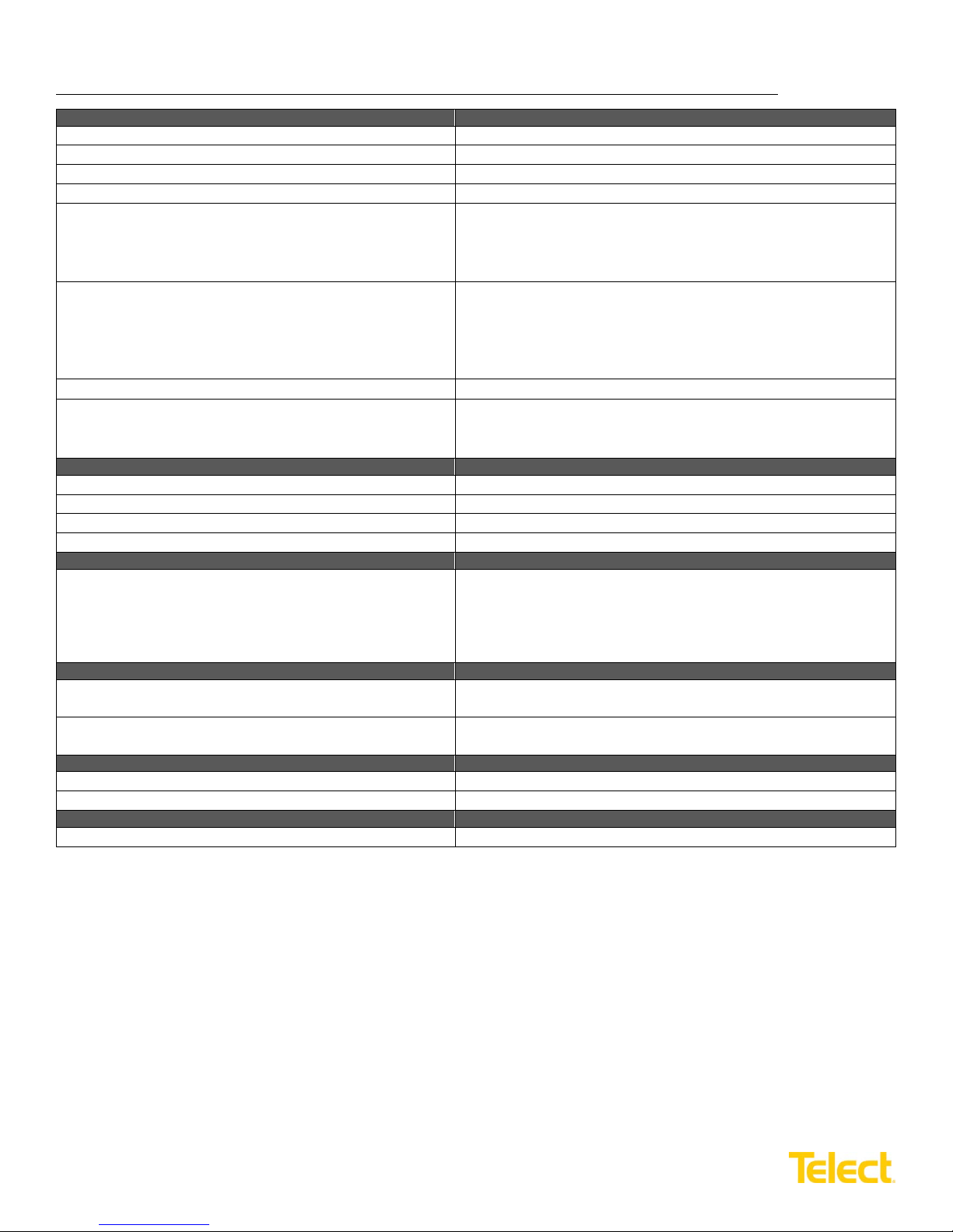
Outputs:
Specifications:
Max. output circuit breaker or fuse holder
Single-pole: 100A; Double-pole: 175A
Max. output load – continuous
Single-pole: 80A; Double-pole: 140A
Minimum short circuit interrupt rating
5000A
Max. total output load
550A per side
Output terminal studs (with KEPS nuts and washers) for
1
/
5
/
Output wire size
• #10 AWG (min.) for a 25A single-pole interrupter to #2 AWG (min.)
4/0 AWG (min.) for quad-pole interrupters
Circuit breakers*
• AIRPAX®-style LEL or Carling-style CA1**
Fuses and fuse holders
• TFD fuse holders for single-pole TLS or TPS fuses
TPW fuse holders for double-pole TPC fuses
Alarms:
Specifications:
Alarm relay contacts
2A @ 30 VDC; 0.6A @ 60 VDC
Max. alarm card power rating
@24V: 103 mA (2.47W); @48V: 128 mA (6.14W)
Alarm wire size
#24 AWG, typical (#26 to #20 AWG)
Alarm terminals
Wire wrap
Dimensions:
Specifications:
600CB10 width (all models)
Depth
19-in. (483 mm)
12-in. (305 mm)
Dimensions:
Specifications:
Weight, without packaging and accessories
600CB10: 18 lbs. (8.2 kg); 600CB12: 22 lbs. (10 kg)
Weight, s hipping
600CB12: 25 lbs. (11 kg); 600CB12: 30 lbs. (14 kg)
Environment:
Specifications:
Operating temperature
-10°C (14°F) to 55°C (131°F)
Humidity
90%, non-condensing
Compliance:
Specifications:
UL Recognized, NEBS Level 3
600CB10 & 600CB12 Installation Guide
dual-hole compression lugs
600CB12 width (all models)
Height
-20 studs on
4
(15.8 mm) for a BATT terminal and 0.70 (17.7 mm) for a RTN
terminal]. Torque bolts (using
(5.5 N•m), max.
for a 100A single-pole inter rup t er
• #2 AWG (min.) for double-pole interrupters from 100 to 175A
• 2/0 AWG (min.) for triple-pole interrupters
•
• TPC DC-BBE-3 fuse holders for single-pole TPC fuses
•
23-in. (584 mm)
3.5-in. (88 mm)
-in. centers [max. lug width of 0.625-in.
8
7
/
-in. or 12 wrench) to a 50-in./lb.
16
* Telect suggests you avoid using different types of circuit breakers or fuses in the same load center. Alarm contacts may
vary among interrupter manufacturers and may incapacitate the alarm system.
** Circuit breakers for this load center are designed and manufactured by Airpax Corporation and Carling Industries to
meet Telect’s specifications. Order circuit breakers only from Telect.
© Telect, Inc. All rights reserved. 7.14.17 136429-2
509.926.6000 :: www.telect.com
600CB10-xL: 21 lbs. (9.5 kg); 600CB12-xL: 25 lbs. (11.3 kg)
600CB12-xL: 28 lbs. (12.7 kg); 600CB12-xL: 33 lbs. (15 kg)
3
Page 7

Dual-Feed 600A Load Center Frame
600CB10 & 600CB12 Installation Guide
ALERT! Only qualified technicians may install and maintain this product. Verify all connections meet
requirements specified in local electric codes or operating company guidelines before supplying power.
Protect this equipment with a fuse or breaker sufficient to interrupt power levels specified.
Install this product in locations accessible only to qualified personnel. The panel weighs more than 35 lbs.
(~ 16 kg); two persons may be required for handling and installing the Load Center Frame.
1.4 Installation Instructions
Please read these instructions carefully before beginning installation. If assistance is required, call Technical Support at
509.926.6000 or email at [email protected].
• Telect is not liable for shipping damage. If damaged, notify the carrier and call Telect at 509.926.6000 for
further recourse.
• Telect recommends that you install load straps before installing the load center on the rack. Also, install load
straps now for future add-on loads.
• Inspect equipment after unpacking and compare it to the packing list. Immediately report any shipping damage,
defects or missing parts to Telect at 509.926.6000. Keep all documentation that comes with your shipment.
1. Assign interrupter positions and install load straps for those positions before installing the load center in a rack
as follows:
a. Choose interrupter positions for breakers or fuses.
You may mix interrupter ratings and single- and multi-pole interrupters in the same load center. Telect
recommends not mixing fuses with circuit breakers.
• Avoid mixing non-mid-trip and mid-trip breakers.
• Avoid mixing TLS/TPS with TPC fuses. (TLS and TPS fuses are compatible but made by
different manufacturers.)
• Do not use multiple, single-pole breakers or fuses with multi-pole load straps.
b. Record interrupter position(s) and amperage of each intended interrupter.
• To mitigate heat buildup caused by heavy loads ≥ 100A, plan a space on one side of the interrupters.
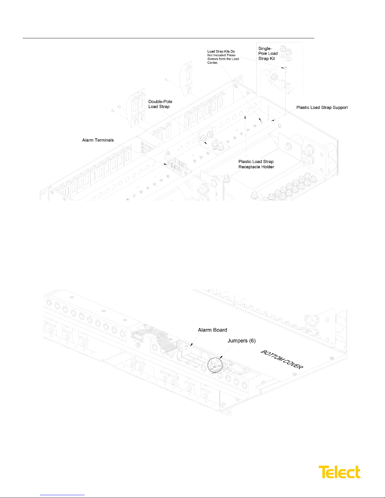
c. Remove bottom screw holding circuit breaker cover to selected interrupter positions. Refer to Figure 2.
• Retain screw and cover if you intend to use circuit breaker
• Retain screw but discard cover if you intend to use fuses
• Remove corresponding screw in plastic load-strap support
• Slip receptacle(s) of load strap into plastic load strap receptacle holder and fasten with screw removed in the
previous step
© Telect, Inc. All rights reserved. 7.14.17 136429-2
509.926.6000 :: www.telect.com
4
Page 8
Dual-Feed 600A Load Center Frame
(Bottom View of Side A)
600CB10 & 600CB12 Installation Guide
2. Turn over the load center and check the jumper settings on the alarm board located on the underside of the chassis.
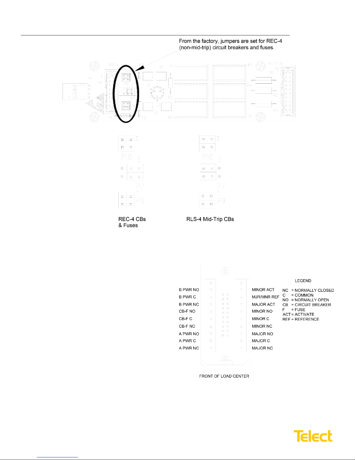
Refer to Figures 3 and 4. The jumpers are set up for REC-4 (non-mid-trip) circuit breakers and fuses. If you plan on
using RLS-4 mid-trip circuit breakers, change the jumper setting as indicated.
Figure 2 – Installing Load Straps
© Telect, Inc. All rights reserved. 7.14.17 136429-2
509.926.6000 :: www.telect.com
Figure 3 – Alarm Board Location
5
Page 9
Dual-Feed 600A Load Center Frame
Figure 4 – Alarm Board Jumper Settings
Figure 5 – Alarm Wiring
600CB10 & 600CB12 Installation Guide
3. If you intend to install alarm wiring for load center
and/or bay alarms, consider doing so now before
installing the load center in the rack. The alarm
terminal is located near the top center of the load
center. Refer to Figure 5.
a. If you intend the alarm wires to exit at the back
of the rack, don’t forget to feed alarm wiring
from the back to the front of the rack before wire
wrapping the alarm pins.
b. It is possible to use a short, manual wire-wrap
tool to install alarm wiring after securing the load
center to the rack. If you intend to use a power
or larger manual wire-wrap tool, you must install
alarm wiring now.
© Telect, Inc. All rights reserved. 7.14.17 136429-2
509.926.6000 :: www.telect.com
6
Page 10
Dual-Feed 600A Load Center Frame
600CB10 & 600CB12 Installation Guide
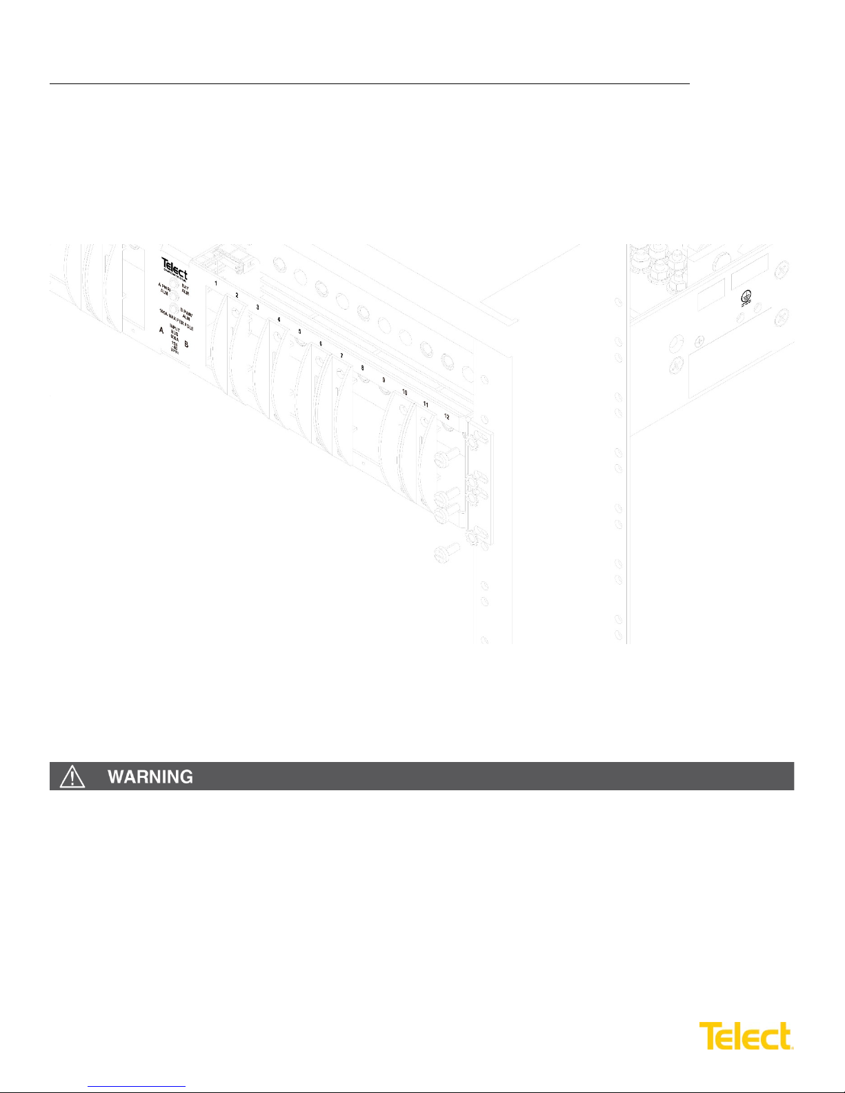
4. Locate an unused rack position and mount the load center using at least two sets of fasteners per side, as shown in
Figure 6.
Mount the panel as high as possible on the rack, leaving at least 1RU of access space above the load center. Tighten
screws to 35-in./lb. (4.29 N•m).
Telect recommends using a seismic rack for best rigidity.
WARNING! Failure to properly ground this eq uipment can create hazardous conditions to installation personnel
and to the equipment.
Figure 6 – Rack Mounting
© Telect, Inc. All rights reserved. 7.14.17 136429-2
509.926.6000 :: www.telect.com
7
Page 11
Dual-Feed 600A Load Center Frame
600CB10 & 600CB12 Installation Guide
ALERT! Only use components and crimping tools approved by agencies or certifying bodies recognized in your
country or region such as Underwriter’s Laboratories (UL), TUV, etc.
5. Use an approved crimping tool to attach approved, dual-hole compression lug onto suitable grounding wire.
(Size of ground depends on input interr upt ion de vice .)
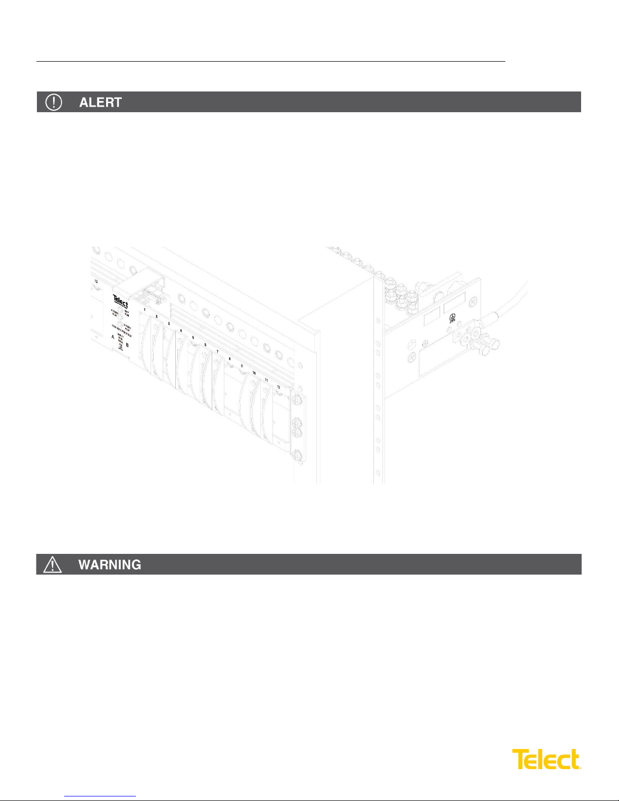
6. If required, lightly coat antioxidant on lug and grounding surface on side of panel. Connect the lug using
flat washers and split washers provided, as shown in Figure 7. Tighten the bolt to 50-in./lb. (5.5 N•m).
1
/4-20 bolts,
Figure 7 – Ground Lug Connection
WARNING! Before connecting input power cables, make sure input power to the panel is turned off.
7. Make sure input power is off before connecting the panel’s input cables to PDU or battery.
8. For input wiring, crimp dual-hole compression lugs onto #1 AWG to 750 MCM copper wires. The choice of input
wiring depends on the following criteria:
• Input interrupt device rating affects size of input wiring.
• Ambient operating temperature affects the type of input wire insulation. Use the table on the following page
to choose the correct temperature-rated input wires. For further information, consult the National Electrical
Code (NEC).
© Telect, Inc. All rights reserved. 7.14.17 136429-2
509.926.6000 :: www.telect.com
8
Page 12
Dual-Feed 600A Load Center Frame
Ambient Operating Temperature Range
Max. Current Rating Per Side
Min. Cable Insulation Temperature Rating
-5° to 49°C (23° to 120°F)
600A
75°C (167°F)
49° to 55°C (120° to 131°F)
550A
75°C (167°F)
49° to 55°C (120° to 131°F)
600A
90°C (194°F)
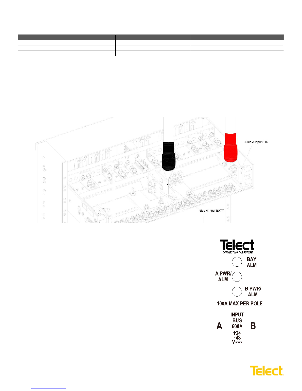
Figure 9 – LED Panel
600CB10 & 600CB12 Installation Guide
9. Insulate the lug barrels with UL94 V-0 rated heat shrink tubing.
10. Clean terminals and lugs with a non-abras i ve, non-metallic pad.
11. If required, lightly coat antioxidant on lugs and input BATT and RTN terminals a nd then co nnect lu gs to input
terminals, as shown in Figure 8. Tighten lugs to 150-in./lb. (~17 N•m), max.
Figure 8 – Input Lugs
12. Make sure the breaker or fuse holder positions are either empty, off or
contain dummy fuses (phony, inoperative, all-plastic slugs).
13. Enable the fuse or breaker at primary distribution unit or battery
(750A max.) to turn on Feed A to Side A of load center and then
check voltage and polarity at input connectors of the panel.
Verify the following:
• A PWR LED on front of panel turns green
• B PWR LED turns red
14. With A PWR LED green (normal operation) – but with B PWR LED red
(off or failure operation) – test A PWR relay and contact alarm terminal:
• Expect continuity (0Ω) between Terminals C and NC
• Expect an open circuit (∞Ω) between Terminals C and NO
© Telect, Inc. All rights reserved. 7.14.17 136429-2
509.926.6000 :: www.telect.com
9
Page 13
Dual-Feed 600A Load Center Frame
600CB10 & 600CB12 Installation Guide
15. Also, test fuse alarm relay contacts at CB-F alarm terminals.
• Expect continuity (0Ω) between Terminals C and NC
• Expect an open circuit (∞Ω) between Terminals C and NO
16. Repeat Steps 13 and 14 to power up Side B. A PWR and B PWR LEDs must both be green.
17. Make sure input power is off again before instal ling out put w irin g to this devic e.
18. For output wiring, crimp dual-hole lugs onto one end of #10 to #2/0 AWG copper output wires, as required by NEC.
(Work with one output wire at a time.)
19. Insulate lug barrels with UL94 V-0 rated heat shrink tubing.
20. Clean the panel terminal and lugs with non-abrasive, non-metallic pad.
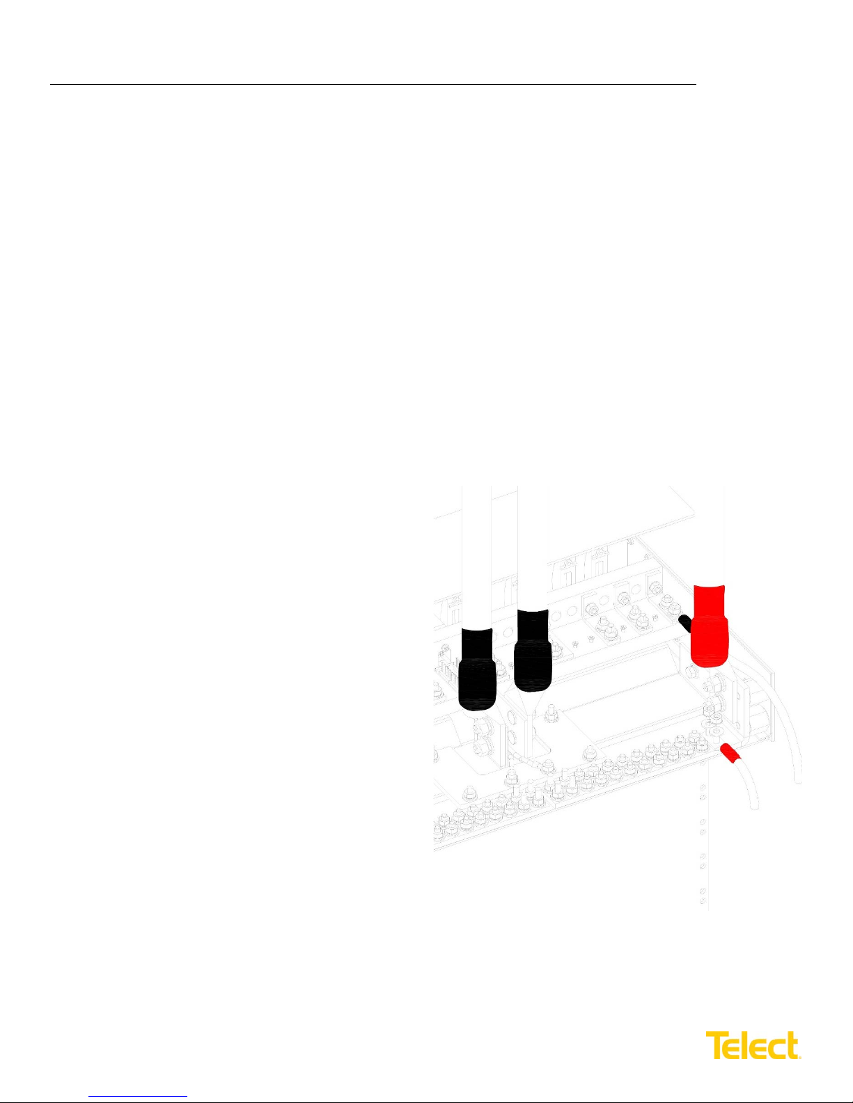
21. If required, lightly coat antioxidant on lugs and output BATT and RTN terminals and then connect lugs to terminals, as
shown in Figure 10. (NEC specifics only one lug and load at each output terminal.) Tighten nuts to no more than 50in./lb. (5.6 N•m), max. Then connect other end of output wire to load.
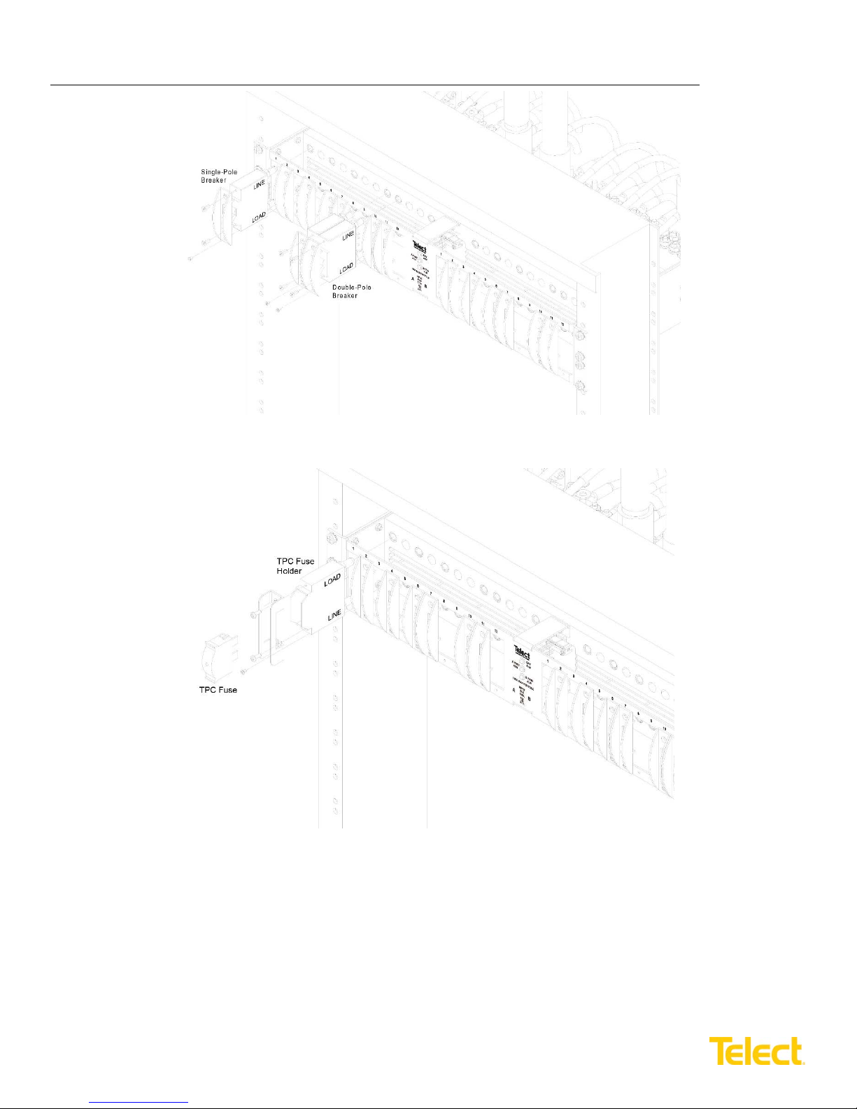
22. Install circuit breakers or fuses, as shown in Figures 11 and 12.
a. Use screws provided with circuit breaker or fuse
holder to attach cover to breaker or holder. (Use
the cover removed previously for circuit breakers.
The fuse holder requires a cover.)
b. Insert a breaker in the load center frame. (“Line”
is on top. Breaker is “upside down” so ON toggle
is up.) Or, insert holder in load center frame
(“Load” is on top.)
c. Fasten the cover to the load center using the
screw previously removed with the cover in Step 1.
d. If applicable, install fuse.
© Telect, Inc. All rights reserved. 7.14.17 136429-2
509.926.6000 :: www.telect.com
Figure 10 – Output Lug Connections
10
Page 14
Dual-Feed 600A Load Center Frame
600CB10 & 600CB12 Installation Guide
Figure 11 – Installing Circuit Breakers
Figure 12 – Installing Fuse Holders and Fuses
23. With the output loads (devices fed by this load center) disabled, re-enable fuses or breakers at primary distribution
unit or battery.
24. If applicable, switch circuit breakers ON and then check voltage and polarity at loads.
© Telect, Inc. All rights reserved. 7.14.17 136429-2
509.926.6000 :: www.telect.com
11
Page 15

Dual-Feed 600A Load Center Frame
600CB10 & 600CB12 Installation Guide
25. If possible, either replace one of the functioning fuses with a blown fuse or switch OFF breaker.
• For a load center with fuses or non-mid-trip circuit breakers, the applicable ALM LED will turn red
• For a load center with mid-trip breakers, the applicable ALM LED will remain green
26. Check the CB-F alarm terminals. For a load center with fuses or non-mid-trip circuit breakers, expect the following:
• An open circuit (∞Ω) between Terminals C and NC
• Continuity (0Ω) between Terminals C and NO
27. For a load center with mid-trip breakers, expect the following:
• Continuity (0Ω) between Terminals C and NC
• An open circuit (∞Ω) between Terminals C and NO
28. Re-install operable fuses or switch ON breakers before proceeding.
29. Record circuit assignments in accordance with operating company procedures and guidelines.
30. Lastly, enable equipment loads one at a time to verify proper operation of loads.
© Telect, Inc. All rights reserved. 7.14.17 136429-2
509.926.6000 :: www.telect.com
12
Page 16
Dual-Feed 600A Load Center Frame
Single-pole
Breakers
Part Number
Multi-pole
Breakers
Part Number
30A
116671
125A (2-pole)
134634
40A
116672
150A (2-pole)
134635
50A
116673
175A (2-pole)
135921
60A
118160
200A (3-pole)
134636
70A
118161
225A (3-pole)
134637
80A
118162
250A (3-pole)
134638
90A
118163
400A (4-pole)
143962
100A
118159
Adapter2
(1" C-C)
600CB08-RPK
Panel
Part Number
600A Dual-feed 10/10 load center frame,
vertical inputs
600CB10
600A Dual-feed 10/10 load center frame,
600CB10-C
600A Dual-feed 10/10 load center frame,
vertical, loaded
600CB10-VL
600A Dual-feed 10/10 load center frame,
horizontal, loaded
600CB10-CL
600A Dual-feed 12/12 load center frame,
600CB12
600A Dual-feed 12/12 load center frame,
600CB12-C
600A Dual-feed 12/12 load center frame,
vertical, loaded
600CB12-VL
600A Dual-feed 12/12 load center frame,
600CB12-CL
Adapter kit to mount 600CB10 in a 23" rack
02117-02+746
Adapter kit for double-pole input
1
600CB1X-2FA
Fuses
TPC
TPS
TLS
25A
125441
130476
N/A
30A
125442
130478
N/A
40A
125443
130482
N/A
50A
125444
130484
N/A
60A
125445
130486
N/A
70A
N/A
130488
N/A
75A
125446
N/A
N/A
80A
N/A
N/A
140640
90A
125447
N/A
140641
100A
125448
N/A
140642
125A
125449
N/A
140644
TPC fuse holder
3
129347
TFD fuse holder
3
129816
Fuse holder cover
4
600CBXX-CFK
Load Connections
Part Number
Single-pole
600CB1X-1PK
Double-pole
600CB1X-2PK
Triple-pole
600CB1X-3PK
Four-pole
600CB1X-4PK
600CB10 & 600CB12 Installation Guide
1.5 Parts & Accessories
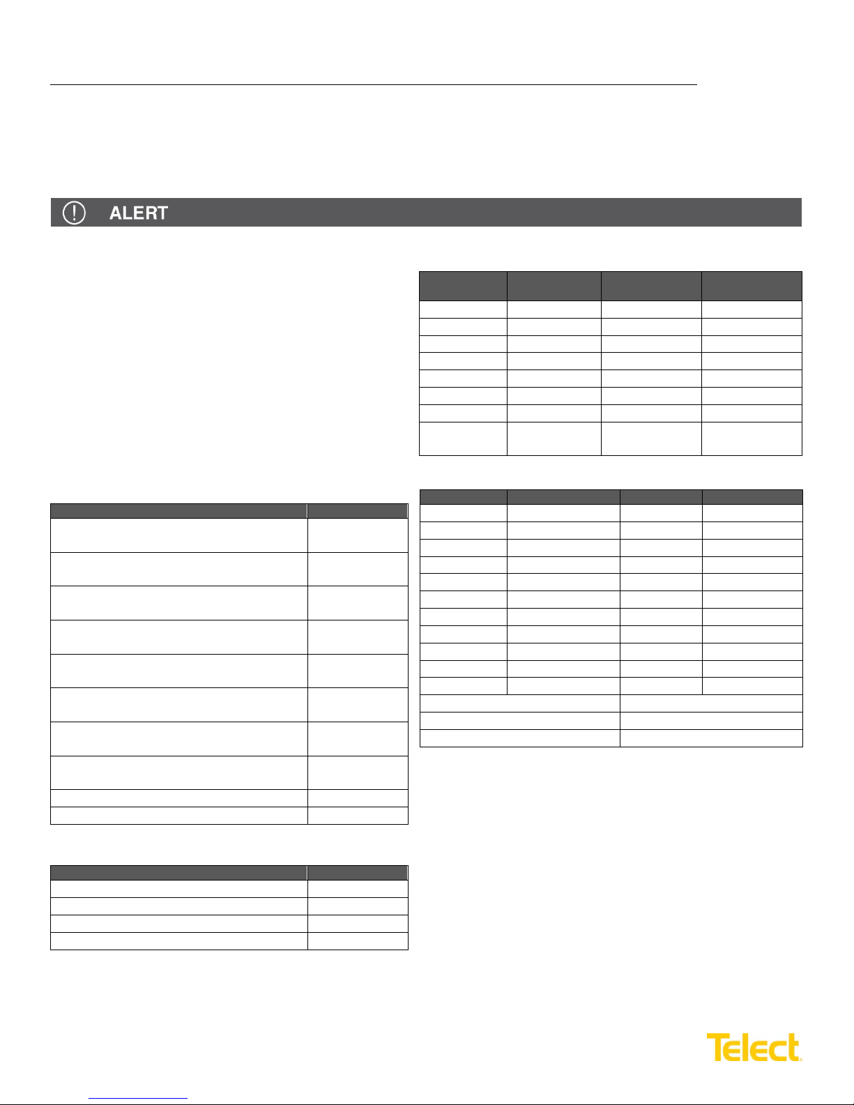
The following tables list optional and replacement items for the load center. For wire sizing and labeling, please refer to
Wire Sizing & Label Convention (Telect part number 117995) included with your load center. Order parts and accessories
online at telect.com.
ALERT! Use only UL-listed or UL-recognized component secondary protection devices.
Steps for configuring a panel:
1. Choose vertical or horizontal input.
2. Determine the quantity of load connections
required (one load connection per populated
fuse or circuit breaker position).
3. Choose multi-pole connections if required.
4. Select circuit breakers or fuses:
• If fuses, choose TPC or TFD holders
• If circuit breakers (or fuse holders), select
quantity equal to number of load connections
• Select circuit breaker or fuse amperage values
horizontal inputs
vertical inputs
horizontal inputs
horizontal, loaded
(for TPS/TLS fuses)
1
Two kits are required for dual feed inputs.
2
Required when using the 600CB1X-3PK or 600CB1X-4PK.
3
Holder kits contain fuse holder, cover and fasteners.
4
Load connection kits contain receptacle, strap assembly and lug fasteners.
© Telect, Inc. All rights reserved. 7.14.17 136429-2
509.926.6000 :: www.telect.com
13
Page 17
Dual-Feed 600A Load Center Frame
400 MCM
500 MCM
750 MCM
777.7 MCM
T&B
54216
(Die code 76)
54218
(Die code 87)
--
--
Burndy
YA322TC38
(Die code 19)
YA342TC38
(Die code 20)
YA392NT38
(Die code 24)
YA44L-2NT38-FX
(Die code L115)
Panduit
LCD400-38D-6
(Die code 76)
LCD500-38D-6
(Die code 87)
LCDN750-38D-6
(Die code 106)
--
#8 AWG
#6 AWG
#4 AWG
#2 AWG
#2/0 AWG
T&B
542040410
(Die code 21)
54205
(Die code 24)
54206
(Die code 29)
54207
(Die code 33)
--
Burndy
YA8CL-2TC14
(Die code 49)
YA6CL-2L
(Die code 7)
YA4C-2L
(Die code 8)
YA2CL-2TC14
(Die code 10)
YA26L2NT14
(Die code 13)
Panduit
LCD8-14A-L
(Die code 21)
LCD6-14A-L
(Die code 24)
LCD4-14A-L
(Die code 29)
LCD2-14A-Q
(Die code 33)
LCDN2/0-14A-X
(Die code 45)
600CB10 & 600CB12 Installation Guide
ALERT! Only use components and crimping tools approved by agencies or certifying bodies recognized in your
country or region such as Underwriter’s Laboratories (UL), TUV, etc.
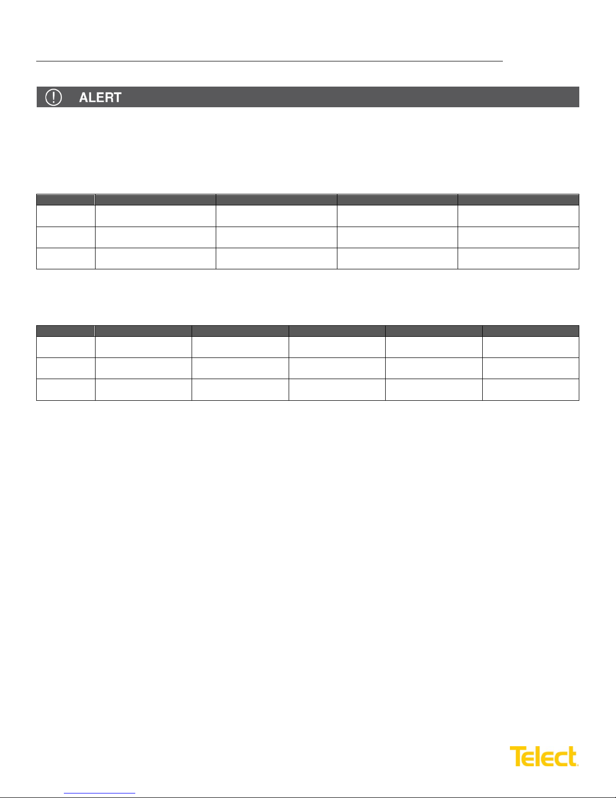
Input Power Lugs
Ground and Circuit Breaker Output Lugs (
1
/4-in. dual-holes on 5/8-in. centers, uninsulated)
© Telect, Inc. All rights reserved. 7.14.17 136429-2
509.926.6000 :: www.telect.com
14
Page 18
Dual-Feed 600A Load Center Frame
600CB10 & 600CB12 Installation Guide
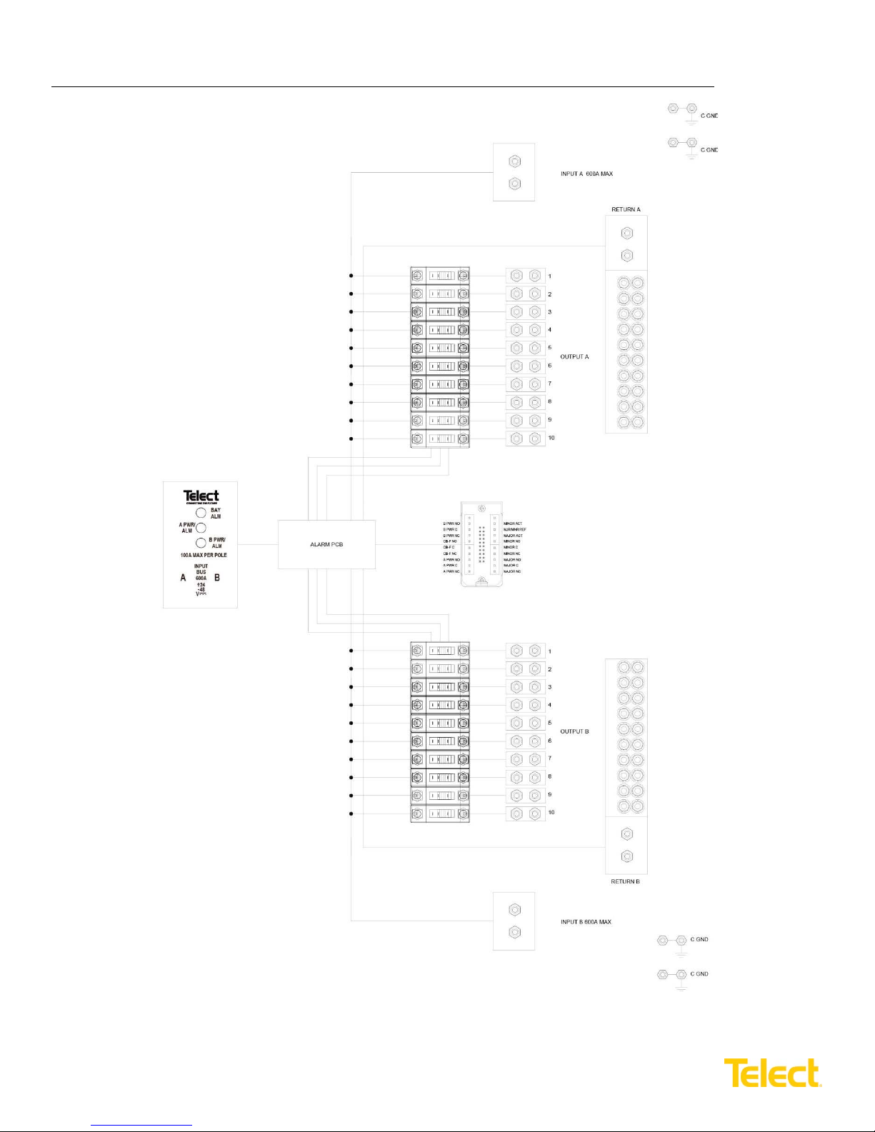
1.6 Interconnections
© Telect, Inc. All rights reserved. 7.14.17 136429-2
509.926.6000 :: www.telect.com
15
Page 19
Dual-Feed 600A Load Center Frame
A
INPUT
BUS
600A
48
24
-
+
-
B
V
- - -
BAY
ALM
A PWR/
ALM
B PWR/
ALM
9 10 1211 9 10 1211
100A MAX PER POLE
23.00 [584.2]
22.31 [566.7]
21.00 [533.4]
1.25 [31.8]
1.75 [44.5]
3.00 [76.2]
0.50 [12.7]
FRONT VIEW
TOP VIEW
12.61 [320.3]
0.73 [18.5]
0.625 [15.9]
¼-20 x ¾ in.
0.625 [15.9]
¼-20 x ¾ in. Stud, KEPS Nut, & Washer
¼-20 x 1 in. Stud, KEPS Nut, & Washer
1.00 [25.4]
1.00 [25.4]
3
8
-16 x 1
1
4
in. Stud, Nut,
Lock Washer, & Flat Washer
3
8
-16 x 1
1
4
in. Stud, Nut,
Lock Washer, & Flat Washer
REAR VIEW
(ROTATED)
12.00 [304.8]
RTN A BUS
RTN B BUS
BATT A BUS
BATT B BUS
RTN A Input Terminal RTN B Input Terminal
BATT A Input Terminal BATT B Input Terminal
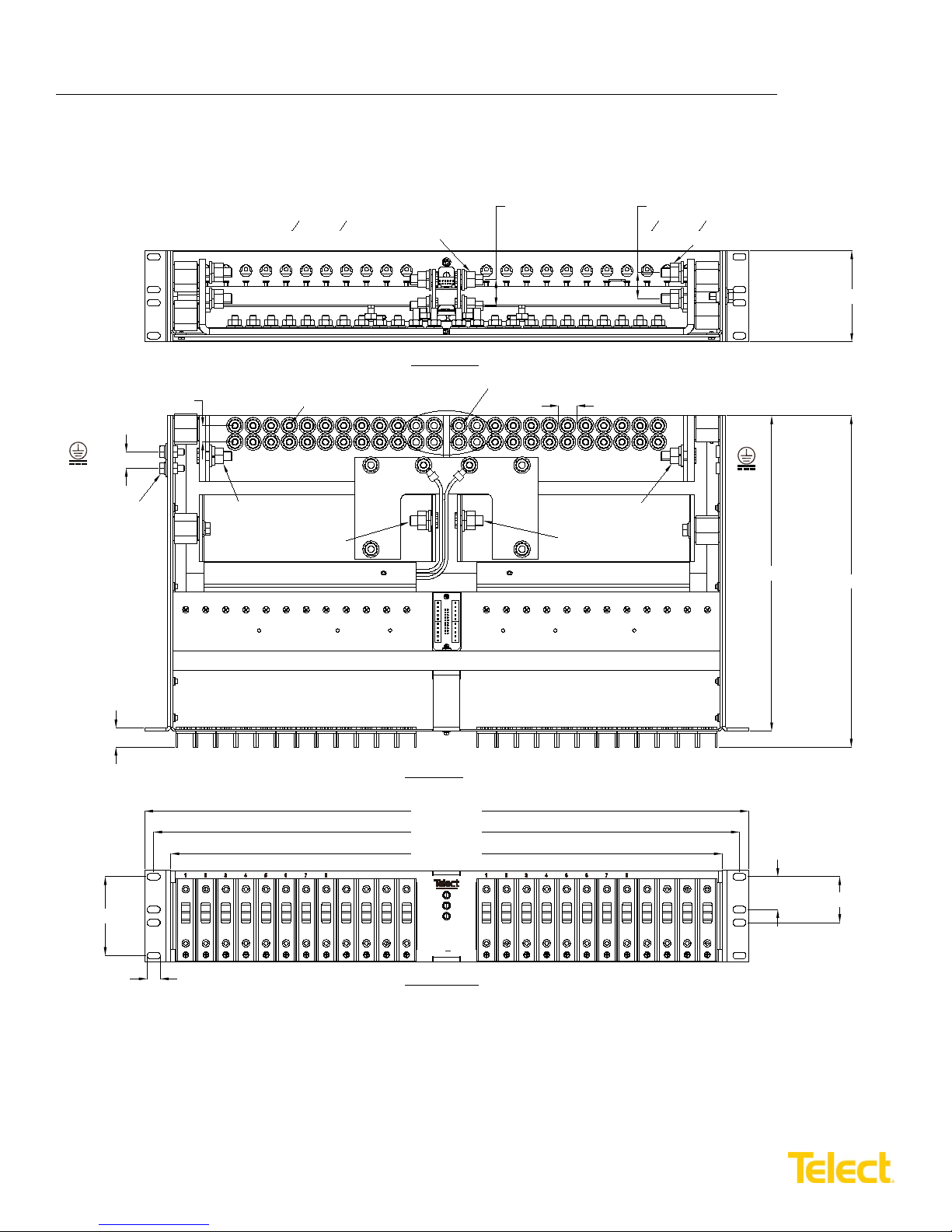
NOTES 1. Dimensions are in in. [mm].
2. Breakers/Fuses sold separately.
3. Breaker/Fuse line straps sold separately.
4. Max lug width for input BATT and RTN is ~50 mm (~2 in.)
0.69 [17.5], Max. Lug Width
(See Note 4.)(See Note 4.)
3.47 [88.1]
600CB10 & 600CB12 Installation Guide
1.7 Drawings
Telect assumes no liability for the application or use of these products. Neither does Telect convey any license under its
patent rights or the patent rights of others. This document and the products described herein are subject to change
without notice.
© Telect, Inc. All rights reserved. 7.14.17 136429-2
509.926.6000 :: www.telect.com
16
Page 20
Dual-Feed 600A Load Center Frame
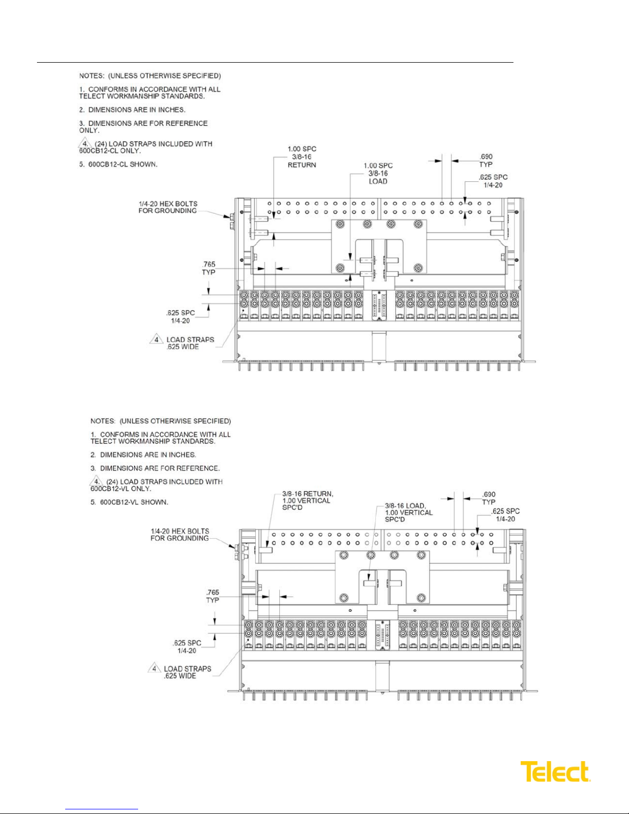
600CB12-CL – Top View
600CB12-VL – Top View
600CB10 & 600CB12 Installation Guide
© Telect, Inc. All rights reserved. 7.14.17 136429-2
509.926.6000 :: www.telect.com
17
 Loading...