

Page 1
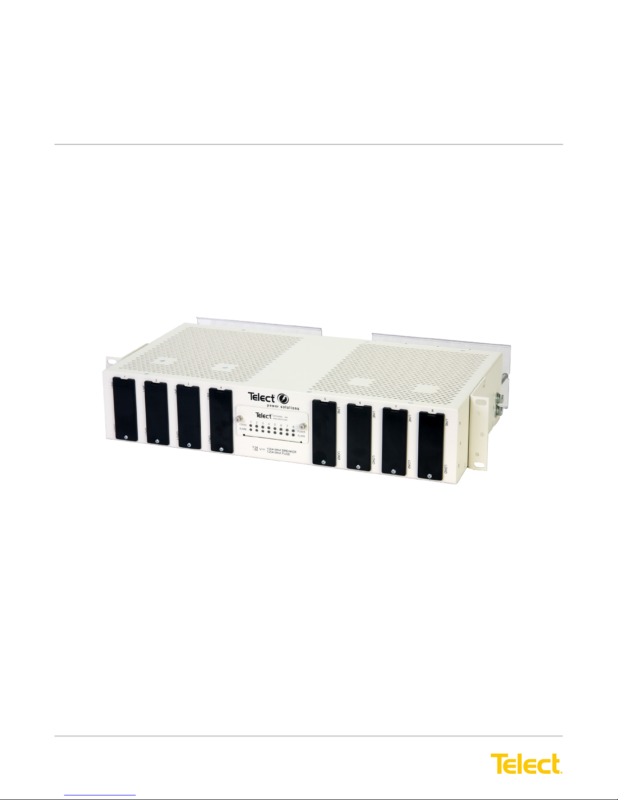
Demarcation Fuse/Circuit Breaker Alarm Panel
Power :: 125DM08
Installation Guide
Applies to : 125DM08
© Telect, Inc., All Rights Reserved, 139695-3 A0
1.509.926.6000 :: telect.com
Page 2

Demarcation Fuse/Circuit Breaker Alarm Panel
Power :: Model 125DM08
Table of Contents
1.1 Overview ......................................................................................................................... 4
1.2 Specications ..................................................................................................................5
1.3 Inspection .......................................................................................................................5
1.4 Installation .......................................................................................................................6
1.4.1 Important Installation Guidelines ............................................................................. 6
1.4.2 Installation Procedure .............................................................................................7
1.5 Replacing Alarm Cards .................................................................................................14
1.6 Accessories ...................................................................................................................15
1.7 Compression Lugs ........................................................................................................ 16
Figures
Figure 1 - Model 125DM08 (UL Listed, File E139903) .........................................................4
Figure 2 - 125DM08 - TFD .................................................................................................... 4
Figure 3 - Bracket Orientation ...............................................................................................8
Figure 4 - Rack Mounting .....................................................................................................8
Figure 5 - Ground Terminal Harware ....................................................................................9
Figure 6 - Ground Terminal Hardware ..................................................................................9
Figure 7 - Input & Output Lug Connections ..........................................................................9
Figure 8 - LEDs on Front Panel .......................................................................................... 10
Figure 9 - Removing Blank Covers ..................................................................................... 10
Figure 10 - Installing Circuit Breaker .................................................................................. 11
Figure 11 - Installing Circuit Breaker ................................................................................... 11
Figure 12 - Installing TFD Fuse Holders ............................................................................. 11
Figure 13 - Installing TPS/TLS Fuses ................................................................................. 12
Figure 14 - Alarm Relay Terminals on Rear of Panel .......................................................... 13
Figure 15 - Alarm Card in Place ..........................................................................................14
Figure 16 - Alarm Card Removed .......................................................................................14
Figure 17 - Typical 125DM08 Circuit .................................................................................. 17
© Telect, Inc., All Rights Reserved, 139695-3 A0
1.509.926.6000 :: telect.com
ii
Page 3
Demarcation Fuse/Circuit Breaker Alarm Panel
Power :: Model 125DM08
1.1 Overview
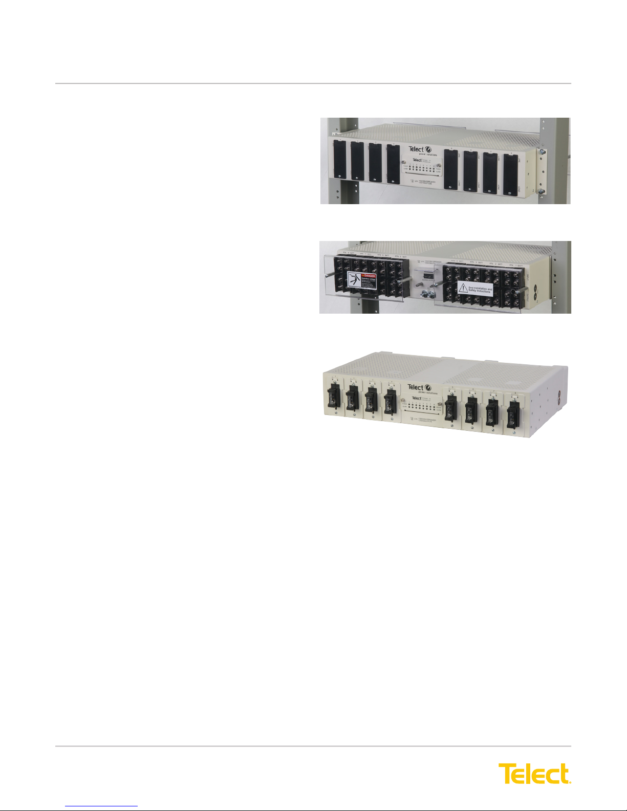
Telect’s Demarcation Fuse/ Circuit Breaker Panel with
Alarms provides TPS/TLS fuse or circuit breaker
protection at the equipment interface. The 2RU, white
panel supports
• eight TFD fuse holders
or
• bullet-style, standard-trip circuit breakers with
rear access terminals
and
• a replaceable alarm card containing power and
alarm LEDs, with rear-access, wire-wrap alarm
relay contacts
Each fuse holder or circuit breaker position has
separate BATT/RTN inputs and outputs rated up to
125A for either +\-24Vdc or -48Vdc applications.
Front
Rear
Figure 1 - Model 125DM08 (UL Listed, File E139903)
Hardware is included for either ush or extended
mounting in a 19-in. or 23-in. relay rack. Visit our
website (www.telect.com) to order accessories and
replaceable parts: fuses (up to 125A),TFD fuse holder,
circuit breakers (up to 100A), ETSI mounting brackets,
and more.
NOTE: The 125DM08-TFD includes eight TFD
holders installed.
Figure 2 - 125DM08 - TFD
© Telect, Inc., All Rights Reserved, 139695-3 A0
1.509.926.6000 :: telect.com
1
Page 4
Demarcation Fuse/Circuit Breaker Alarm Panel
Power :: Model 125DM08
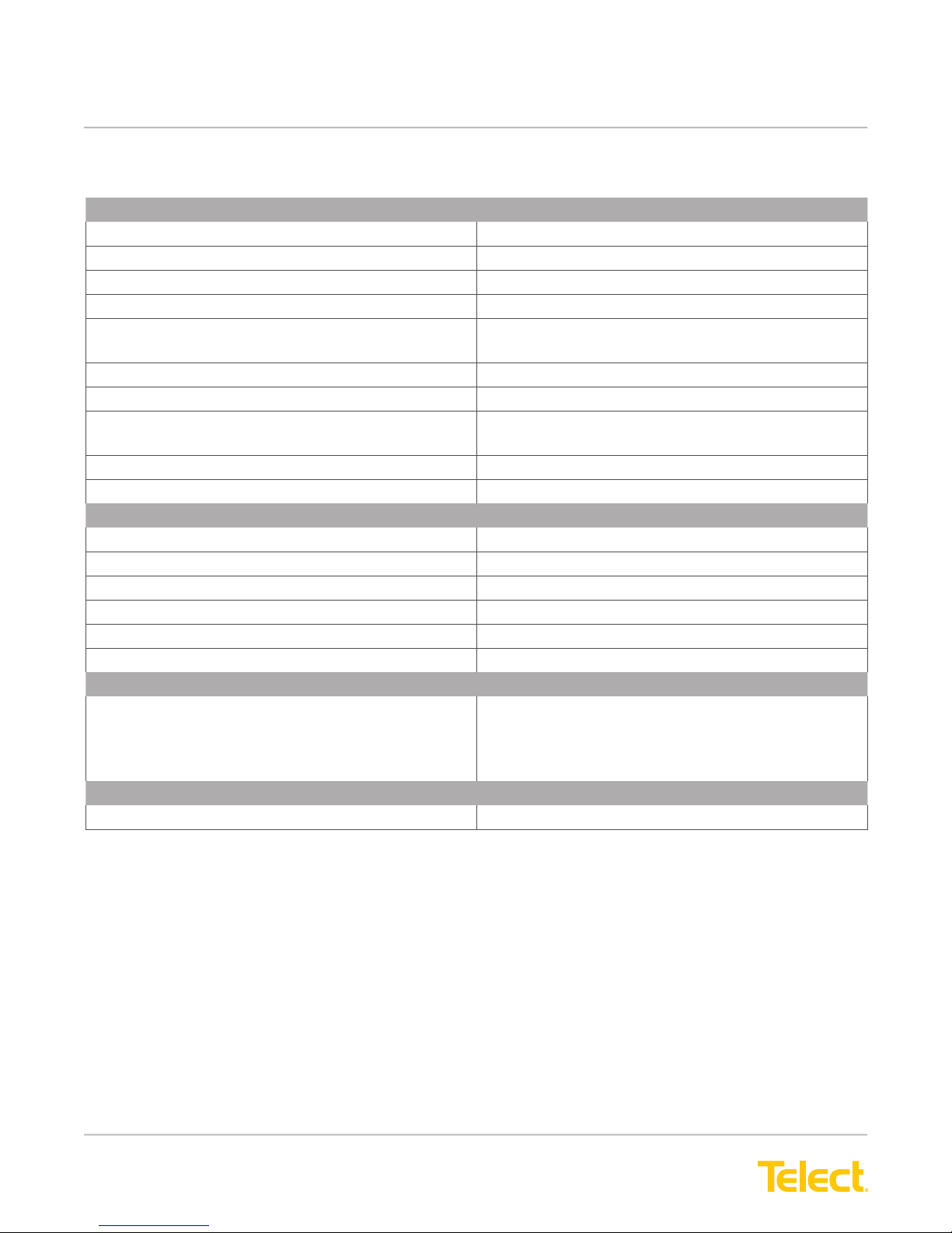
1.2 Specications
Inputs/Outputs: Specication:
Max. Rating Single-Pole, Circuit Breaker (each) 100A
Max. Rating TFD Holder, Schematic C 125A (TLS Fuse); 70A (TPS Fuse)
Max. Continuous Output Load (each) 80% of rated
Max. Total Load Rating of Panel 800A continuous
Voltage Range ±20 to ±28 Vdc
-40 to -60 Vdc
BATT & RTN Wire Size #8 to #1 AWG
Ground Wire Size #10 to #2 AWG (depends on input fuse)
Terminal Stud Sizes
(Input, Output, and Earth Ground)
Power Dissipation 17W per I/O
Short-Circuit Withstand Rating 5000A
Alarms: Specication:
Alarm Relay Contacts 0.6A @ 60 Vdc
Alarm Card Power Rating 1W
Alarm Wire Size Solid: #26 to #22 AWG
Weight: Specication:
Weight, Shipping ~20 lb (~9 kg) - 125DM08
Dimensions: Specication:
Nominal, without brackets:
Width
Height
Depth
Environment: Specication:
Operating Temperature -5°C (23°F) to 50°C (131°F)
¼-20 dual studs on 5/8” centers
¼-20 dual PEMs on 5/8” centers (side ground)
~22 lb (~10 kg) - 125DM08-TFD
17.25 in (43.8 cm)
3.5 in (8.9 cm)
10.84 in. (27.6 cm)
1.3 Inspection
Please read these instructions carefully before beginning installation. If you need assistance, call Technical
Support at 1.888.821.4856 (domestic calls), or 509.921.6161 (Option 2), or email us at [email protected].
Inspect equipment after unpacking and compare it to the packing list. Immediately report any shipping damage,
defects, or missing parts to Telect at 1.800.551.4567. Keep all documentation that comes with your shipment.
© Telect, Inc., All Rights Reserved, 139695-3 A0
1.509.926.6000 :: telect.com
2
Page 5

Demarcation Fuse/Circuit Breaker Alarm Panel
Power :: Model 125DM08
Telect is not liable for shipping damage. If the product is damaged, notify the carrier and call Telect’s Customer
Service Department at 1.800.551.4567 (domestic only) or 1.509.926.6000 for further recourse.
NOTE: For service or warranty information, please visit the telect.com website, or email inquiries to getinfo@
Telect.com and click on the “Support” tab, or phone us at 800.551.4567 (domestic only) or 509.926.6000.
ALERT
!
ALERT! Verify that all connections meet requirements specied in local electric codes or operating
company guidelines before supplying power. Protect this equipment with a fuse or breaker
sufcient to interrupt power levels specied on the preceding pages.
INSTALL THIS PRODUCT WITHIN A RESTRICTED ACCESS LOCATION WHERE ACCESS IS THROUGH
THE USE OF A TOOL, LOCK AND KEY, OR OTHER MEANS OF SECURITY AND IS CONTROLLED BY THE
AUTHORITY RESPONSIBLE FOR THE LOCATION. ONLY QUALIFIED TECHNICIANS MAY INSTALL AND
MAINTAIN THIS PRODUCT.
1.4 Installation
NOTES:
• Fuse holders, fuses, and circuit breakers are sold separately. See “1.6 Accessories” on page 12 for
part numbers.
• Do not remove terminal protection brackets, until panel is installed in a rack. If the panel is transported outside
of the shipping container, make sure the terminal protection brackets are installed.
1.4.1 Important Installation Guidelines
• Elevated Operating Ambient - If you install this product in a closed or multi-unit rack assembly, the
operating ambient temperature of the rack environment may be greater than room ambient. Therefore,
consider installing the equipment in an environment compatible with the maximum ambient temperature
(Tma) specied by the manufacturer.
• Reduced Air Flow - When you install this equipment in a rack, make sure you do not compromise the amount
of air ow required for safe operation of the equipment.
• Mechanical Loading - When you mount the equipment in the rack, make sure to keep the mechanical load
balanced to prevent a hazardous condition.
• Circuit Overloading - Pay attention to the connection of the equipment to the supply circuit and the effect
that overloading of the circuits might have on overcurrent protection and supply wiring. Appropriately consider
equipment nameplate ratings when addressing this concern.
• Reliable Earthing - Maintain reliable earthing of rack-mounted equipment. Pay particular attention to supply
connections other than direct connections to the branch circuit (e.g., use of power strips).
• Disconnect Device - Incorporate a readily available disconnect device into the building installation wiring.
© Telect, Inc., All Rights Reserved, 139695-3 A0
1.509.926.6000 :: telect.com
3
Page 6
Demarcation Fuse/Circuit Breaker Alarm Panel
LINE
LOAD
TPC Fuse Holder
M AK E SU RE A LA RM
C ON NE CTO R O N FU SE H OL DE R
IS STR AI T B EF ORE IN SE R TI NG
IN TO T HE PAN EL
A b en t a larm bay on et on a fuse
ho lder can ei th er ca use int ern al
da m ag e t o the pa ne l or f ail to ma ke
el ect rical cont ac t w ith a larm w iring
w ithi n th e pa ne l.
CAUTION !
Power :: Model 125DM08
1.4.2 Installation Procedure
NOTE: Panel brackets are available for ush mounting in a 19-in. rack. A pair of 23-in. rack brackets are also
included. Either pair of brackets can be moved or installed to extend front of panel beyond the face of the rack in
1-in. (2.54 cm) increments.
WARNING
!
WARNING! Failure to properly ground this equipment can create hazardous conditions to installation
personnel and to the equipment.
NOTE: Input and output wire size for this panel must be rated for the corresponding breaker/fuse size at the
power distribution unit (PDU). The input wiring to this panel may be a greater size to accommodate a voltage drop
from the primary power source.
WARNING
!
WARNING! Before connecting input power cables, make sure input power to panel is turned off.
NOTE: Always follow operating company guidelines when connecting input wiring to the primary power source.
CAUTION
!
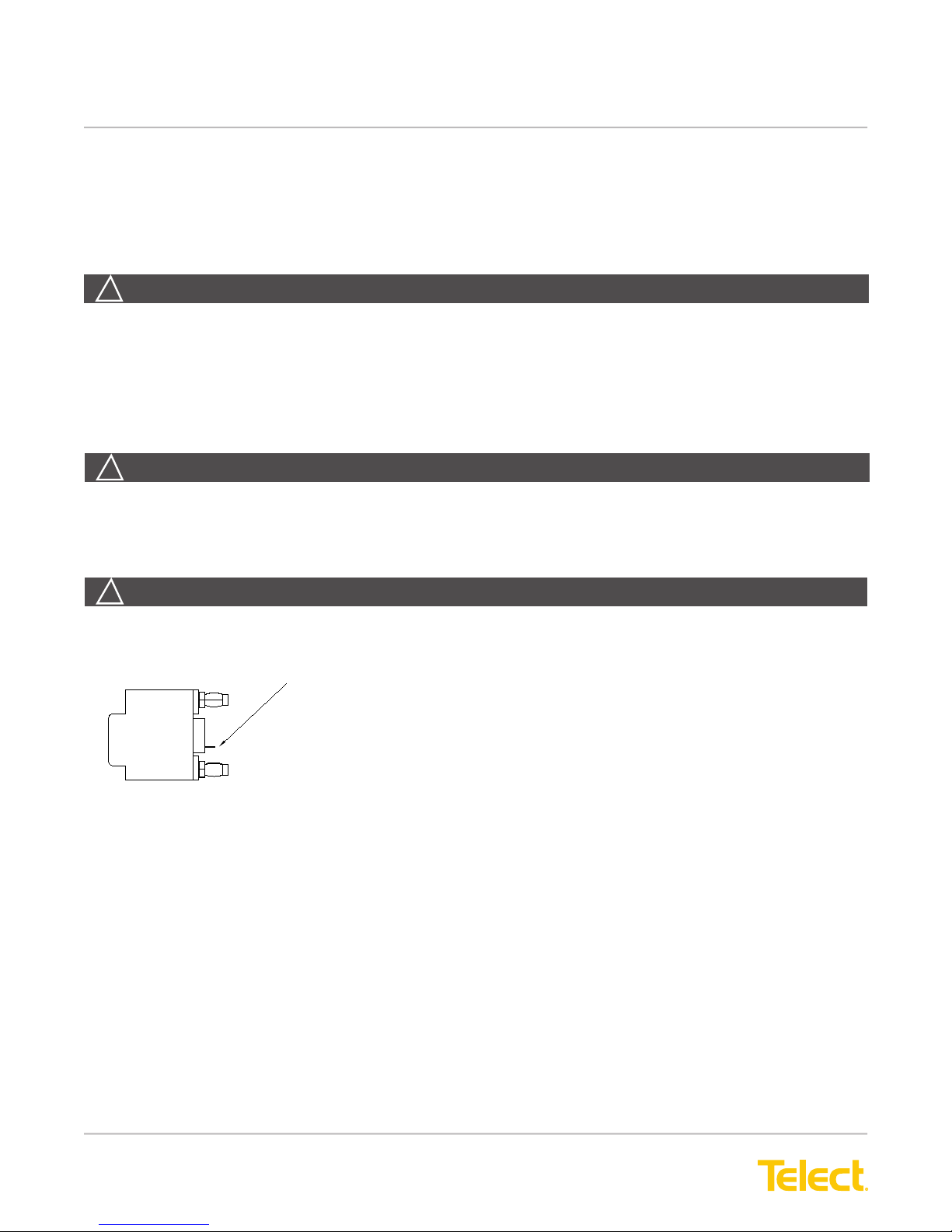
CAUTION!
Make sure the alarm connector on the fuse holder is straight before
LINE
TFD Fuse Holder
inserting into the panel.
A bent alarm bayonet on a fuse holder can either cause internal damage to the
panel or fail to make electrical contact with the alarm wiring within the panel.
LOAD
© Telect, Inc., All Rights Reserved, 139695-3 A0
1.509.926.6000 :: telect.com
4
Page 7
Demarcation Fuse/Circuit Breaker Alarm Panel
Power :: Model 125DM08
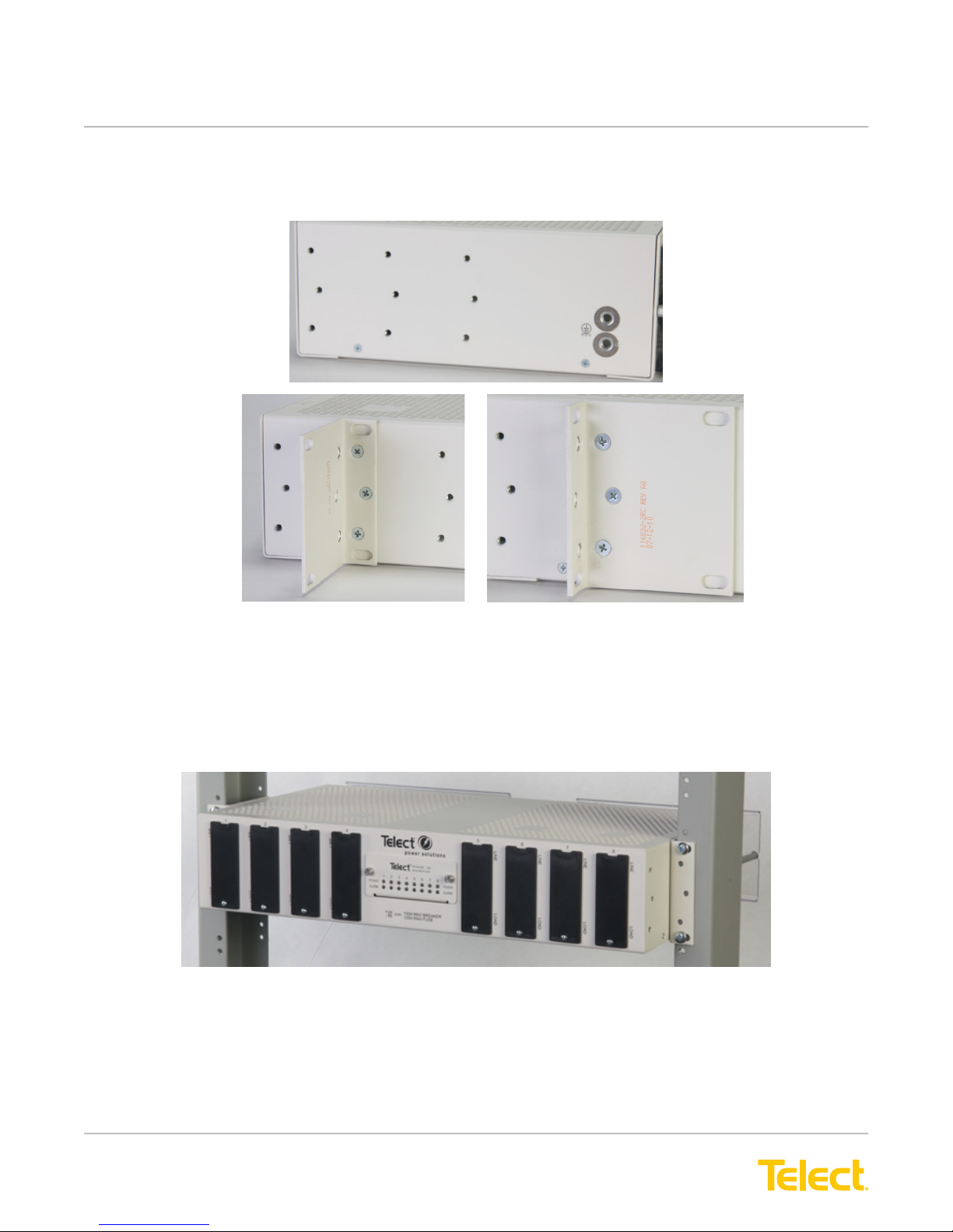
1. If necessary, to move or replace the 19-in. brackets, remove the three screws on the sides of the breaker
panel, as shown in Figure 2.
Figure 3 - Bracket Orientation
2. Install 19-in. or 23-in. brackets for ush or extended panel presentation on rack.
3. Locate an unused rack position and mount panel using the four thread-cutting screws provided, as shown
in Figure 3.
4. Tighten the screws to 35 in.-lb (4.29 N•m).
5. Use a UL/NRTL-approved crimping tool to attach a UL/NRTL-approved, 2-hole compression lug (t 1/4-20
dual studs on 5/8 in. centers) onto a #10 to #2 AWG ground wire. (The size of the ground wire depends on
size of input BATT wires.)
6. Attach the opposite end of the ground wire to the relay rack, per local practices.
Figure 4 - Rack Mounting
© Telect, Inc., All Rights Reserved, 139695-3 A0
1.509.926.6000 :: telect.com
5
Page 8
Demarcation Fuse/Circuit Breaker Alarm Panel
Power :: Model 125DM08
NOTE: The 125DM08 is DC-I, and can be grounded in both CBN and IBN networks. All eight ports have isolated
returns, and the chassis grounds are isolated from all returns. The 125DM08 is suitable for installation in network
telecommunication facilities and in locations where the NEC applies.
7. If required, lightly coat antioxidant on lug, grounding terminal, and contacting surface.
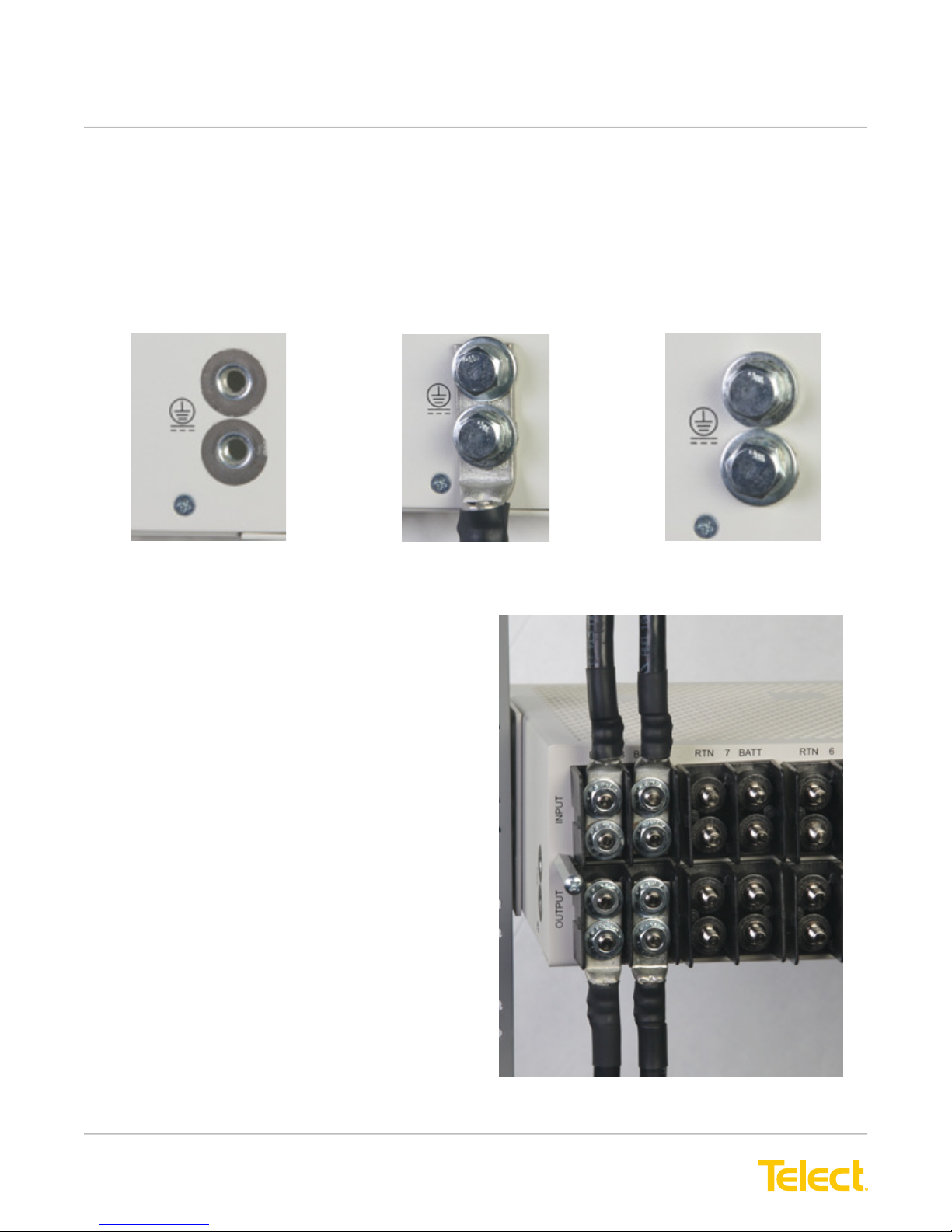
8. Remove the hardware over the terminals on the side of the panel. See Figure 4.
9. Connect the lug to the terminal using the nuts and washers removed in step 8, as shown in Figure 5.
Figure 6 - Ground Terminal Hardware
Figure 5 - Ground Terminal Hardware
10. Tighten the nut to 20 in.-lb (2.27 N•m).
11. Make sure the input power is OFF.
12. For input wiring — wiring used as inputs to this
demarcation panel — crimp straight, 2- hole
compression lugs (t 1/4-20 dual studs on 5/8 in.
centers) onto #8 to #1 copper wires. Insulate lug
barrels with UL94 V-0 rated heat shrink tubing.
13. Clean the terminals with a nonabrasive,
nonmetallic pad.
14. If required, lightly coat anti-oxidant on lugs and
input terminals, and then connect lugs to input
terminals on back of panel, as shown in
Figure 7. Tighten lugs to 50 in.-lb (5.5 N•m).
© Telect, Inc., All Rights Reserved, 139695-3 A0
1.509.926.6000 :: telect.com
Figure 7 - Input & Output Lug Connections
6
Page 9
Demarcation Fuse/Circuit Breaker Alarm Panel
Power :: Model 125DM08
15. Before installing breakers or fuse holders and
output wiring, turn power on to verify input power
and indicators:
• Verify input voltage and polarity.
• Whenever power is supplied, expect the
corresponding PWR ON LED to light.
16. For output wiring, repeat Steps 7 through 12 for
BATT and RTN outputs (crimp output wires to
lugs, clean output terminals, and attach lugs to
output terminals).
17. Heat shrink the insulation onto the lug barrels.
18. Record the circuit assignments on the pull-out
designation card below the alarm display.
19. Install plastic covers over the terminals
CAUTION
!
CAUTION! Telect recommends that the individual
circuit load not exceed 80% of fuse capacity
(for example, 100A fuse x .80 = 80A max. load).
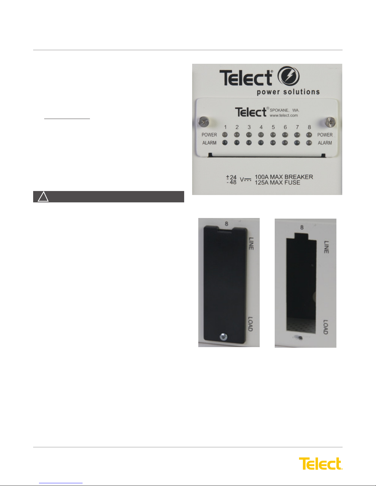
Figure 8 - LEDs on Front Panel
20. Make sure output devices — devices fed from the
outputs of this demarcation panel — are disabled.
21. As shown in Figure 8, remove the blank cover(s)
from the position(s) you plan to use by unscrewing
and removing the small Phillips screw at the bottom.
Keep the hardware for later use.
NOTE: For safety, leave blank covers over all
unused positions.
22. With input power off, rmly install the circuit breakers
or fuse holders in the panel. Make sure the alarm
connectors on the rear of the breakers or holders
are straight before installation. See Figures 8
through 10.
Figure 9 - Removing Blank Covers
© Telect, Inc., All Rights Reserved, 139695-3 A0
1.509.926.6000 :: telect.com
7
Page 10
Demarcation Fuse/Circuit Breaker Alarm Panel
Power :: Model 125DM08
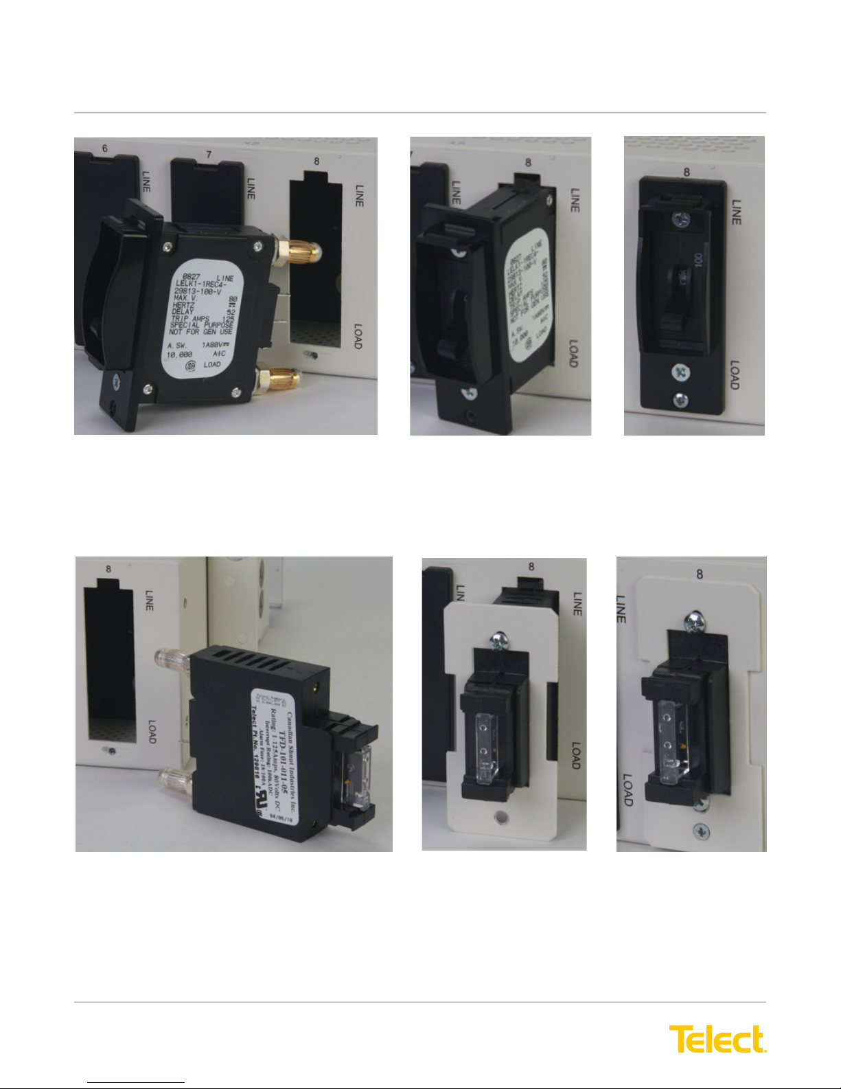
Figure 10 - Installing Circuit Breaker
23. See Figures 9 and 10 for installing circuit breakers.
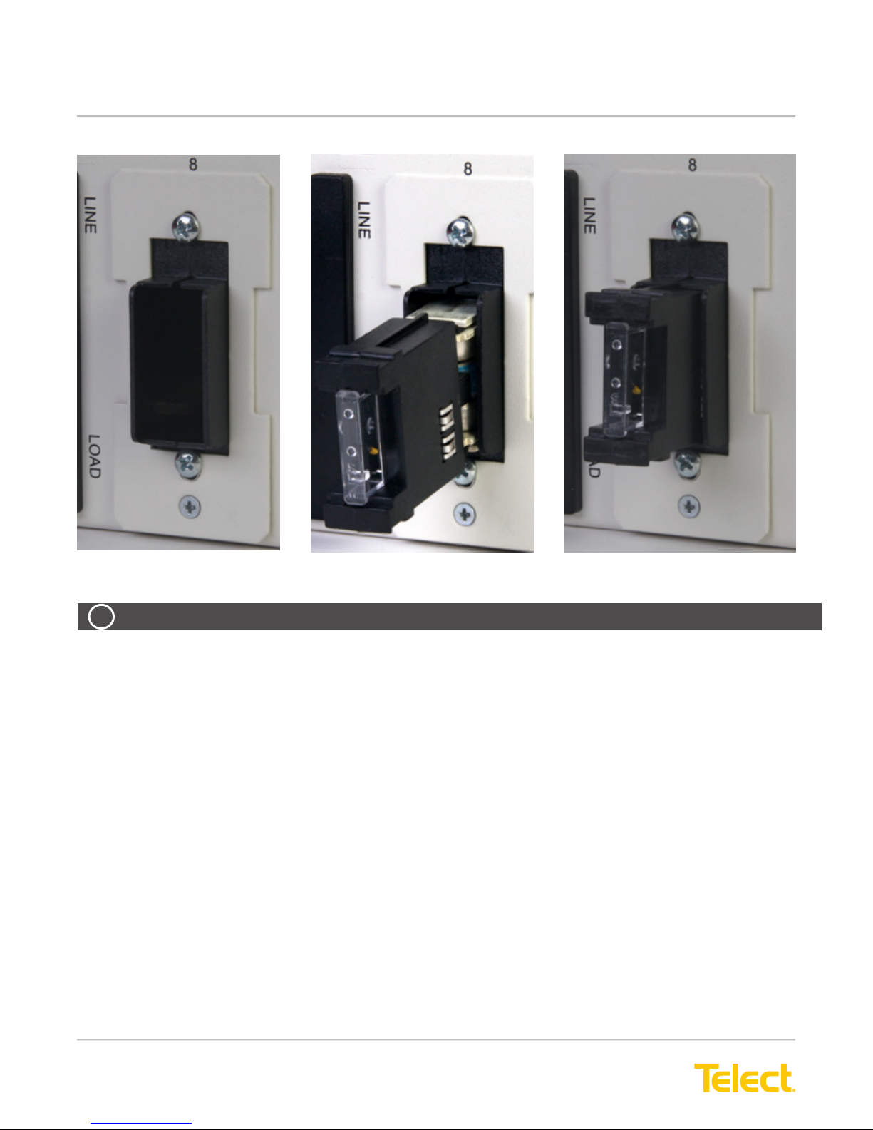
24. See Figures 11 and 12 for installing TFD holders and fuses. Fuse holders are designed so that you can install
them in only one way.
Figure 11 - Installing Circuit Breaker
© Telect, Inc., All Rights Reserved, 139695-3 A0
1.509.926.6000 :: telect.com
Figure 12 - Installing TFD Fuse Holders
8
Page 11
Demarcation Fuse/Circuit Breaker Alarm Panel
Power :: Model 125DM08
Figure 13 - Installing TPS/TLS Fuses
ALERT
!
ALERT! You can install fuse holders backwards. Observe the LINE and LOAD designations on the panel
vs the designations on the fuse holders.
25. Use the screws supplied with each fuse holder or circuit breaker to secure the bezels. Attach the bezel to the
chassis with the blank cover screw previously removed.
© Telect, Inc., All Rights Reserved, 139695-3 A0
1.509.926.6000 :: telect.com
9
Page 12
Demarcation Fuse/Circuit Breaker Alarm Panel
Power :: Model 125DM08
26. Test the Alarm Card:
a. Make sure to apply power to at least one feed,
and make sure that, for each powered feed,
you have installed a valid fuse or circuit breaker
in the ON position.
b. Make sure the Power LED(s) is green and the
Alarm LED(s) is green on the front panel.
Expect an open circuit between C and NO and
a closed circuit between C and NC on the rear
alarm pins.
c. Remove a fuse(s) or turn a circuit breaker(s) to
the OFF position.
d. Verify the Power LED(s) is green and the Alarm
LED(s) is red on the front panel. Expect a
closed circuit between the C and NO and an
open circuit between the C and NO on the rear
alarm pins.
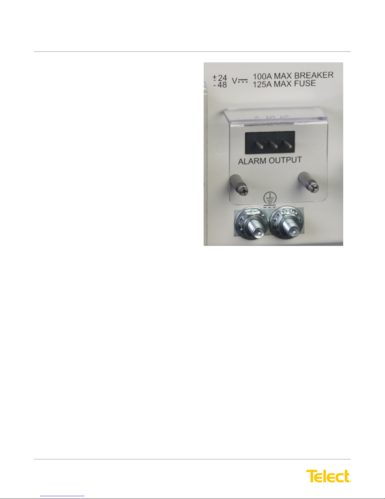
27. Wire-wrap alarm pins with solid #26 to #22 AWG.
28. Enable loads and verify the normal operating con-
ditions outlined in the preceding notes.
Figure 14 - Alarm Relay Terminals on Rear of Panel
© Telect, Inc., All Rights Reserved, 139695-3 A0
1.509.926.6000 :: telect.com
10
Page 13
Demarcation Fuse/Circuit Breaker Alarm Panel
Power :: Model 125DM08
1.5 Replacing Alarm Cards
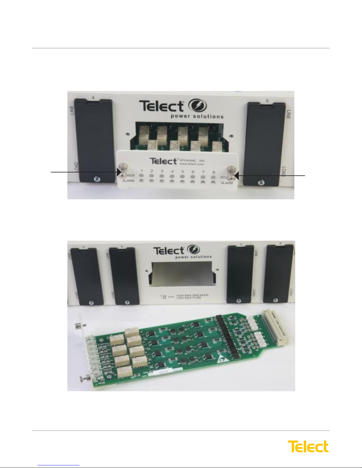
The alarm card is held in place by two captive thumbscrews on the front of the alarm card panel.
Captive
Screw
Figure 15 - Alarm Card in Place
To remove and replace an alarm card, unscrew the thumbscrews and pull out the card.
Captive
Screw
When replacing an alarm card, make sure the edge connector on the far end of the assembly docks securely into
the connector inside the panel.
© Telect, Inc., All Rights Reserved, 139695-3 A0
1.509.926.6000 :: telect.com
Figure 16 - Alarm Card Removed
11
Page 14
Demarcation Fuse/Circuit Breaker Alarm Panel
Power :: Model 125DM08
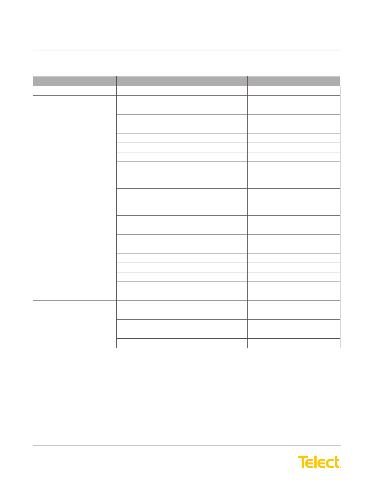
1.6 Accessories
Item Description Part Number
Alarm Card PWR ON / Alarm LED 400747
Circuit Breakers 25A 090-0052-0025
30A 090-0052-0030
40A 090-0052-0040
50A 090-0052-0050
60A 090-0052-0060
70A 090-0052-0070
90A 090-0052-0090
100A 090-0052-0100
TFD Fuse Holder Kit 25-125A with Bullet-Style Connectors for TPS/
TLS fuses with plastic faceplate
25-125A with Bullet-Style Connectors for TPS/
TLS fuses with metal faceplate
TPS Fuses 5A 130481
10A 130485
15A 130487
20A 130489
25A 130476
30A 130478
40A 130482
50A 130484
60A 130486
70A 130488
TLS Fuses 80A 140640
90A 140641
100A 140642
110A 140643
125A 140644
090-0001-0033
090-0001-0034
© Telect, Inc., All Rights Reserved, 139695-3 A0
1.509.926.6000 :: telect.com
12
Page 15
Demarcation Fuse/Circuit Breaker Alarm Panel
Power :: Model 125DM08
1.7 Compression Lugs
ALERT
!
ALERT! Only use components and crimping tools approved by agencies or certifying bodies recognized
in your country or region such as Underwriter’s Laboratories (UL), TUV, etc.
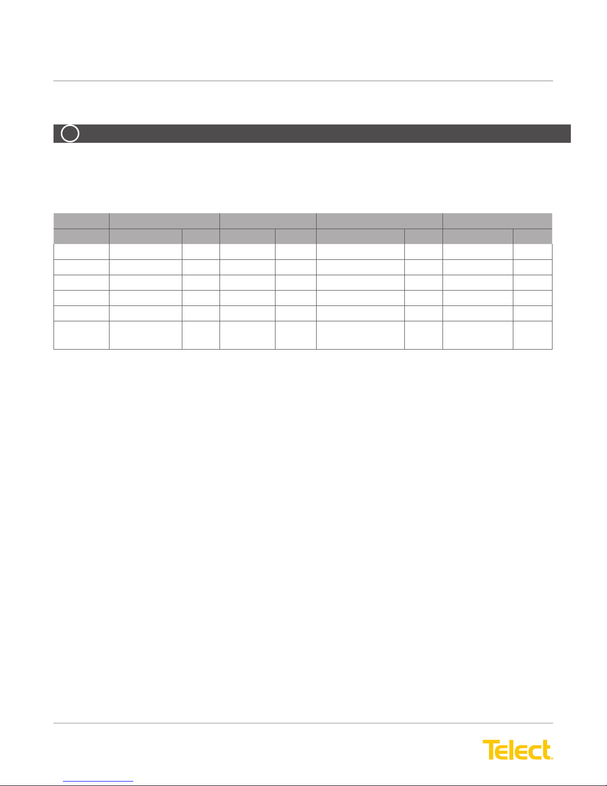
Table 1 - Lugs (Support Dual ¼-20 Studs, 5/8” C-C)
Telect T & B Burndy Panduit
Lug Die Lug Die Lug Die Lug Die
#10 AWG 06117-12
#8 AWG 06117-11
#6 AWG 06117-01
#4 AWG 06117-04
#2 AWG 06117-02
#1 AWG 06117-133 11 YA1CL2NT14 11 LCD2/0-14A-X4P29
1
1
2
2
3
P21 52040410 21 YA8CL-2TC14 49 LCD8-14A-L P21
24 54205 24 YA6CL-2TC14 7 LCD6-14A-L P24
29 54206 29 YA4CL-2TC14 8 LCD4-14A-L P29
10 54207 33 YA2CL-2TC14 10 LCD2-14A-L P33
54201 YAV10-2TC14 LCD10-14A-L
1. 2 lugs included, supplier Panduit
2. 2 lugs included, supplier T&B
3. 2 lugs included, supplier Burndy
4. Lug ts wire size 2/0
© Telect, Inc., All Rights Reserved, 139695-3 A0
1.509.926.6000 :: telect.com
13
Page 16
Demarcation Fuse/Circuit Breaker Alarm Panel
Power :: Model 125DM08
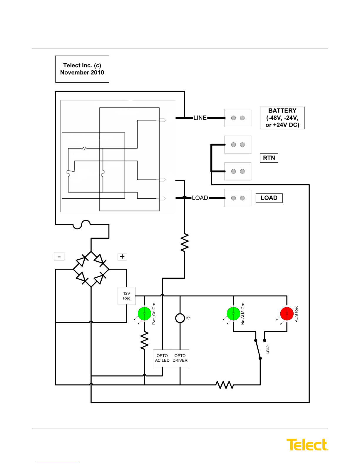
TFD-101-011-05
MAIN HSG
LINE
REMOVABLE CARTRIDGE
RES GEN
R1
2
1
2 OHM, 5W
32
1
FH1
0.180A
GMT-FUSE-HLDR
125V
TPS-TLS
1
F1
2
ALARM
LOAD
© Telect, Inc., All Rights Reserved, 139695-3 A0
1.509.926.6000 :: telect.com
Figure 17 - Typical 125DM08 Circuit
14
Page 17
Demarcation Fuse/Circuit Breaker Alarm Panel
Power :: Model 125DM08
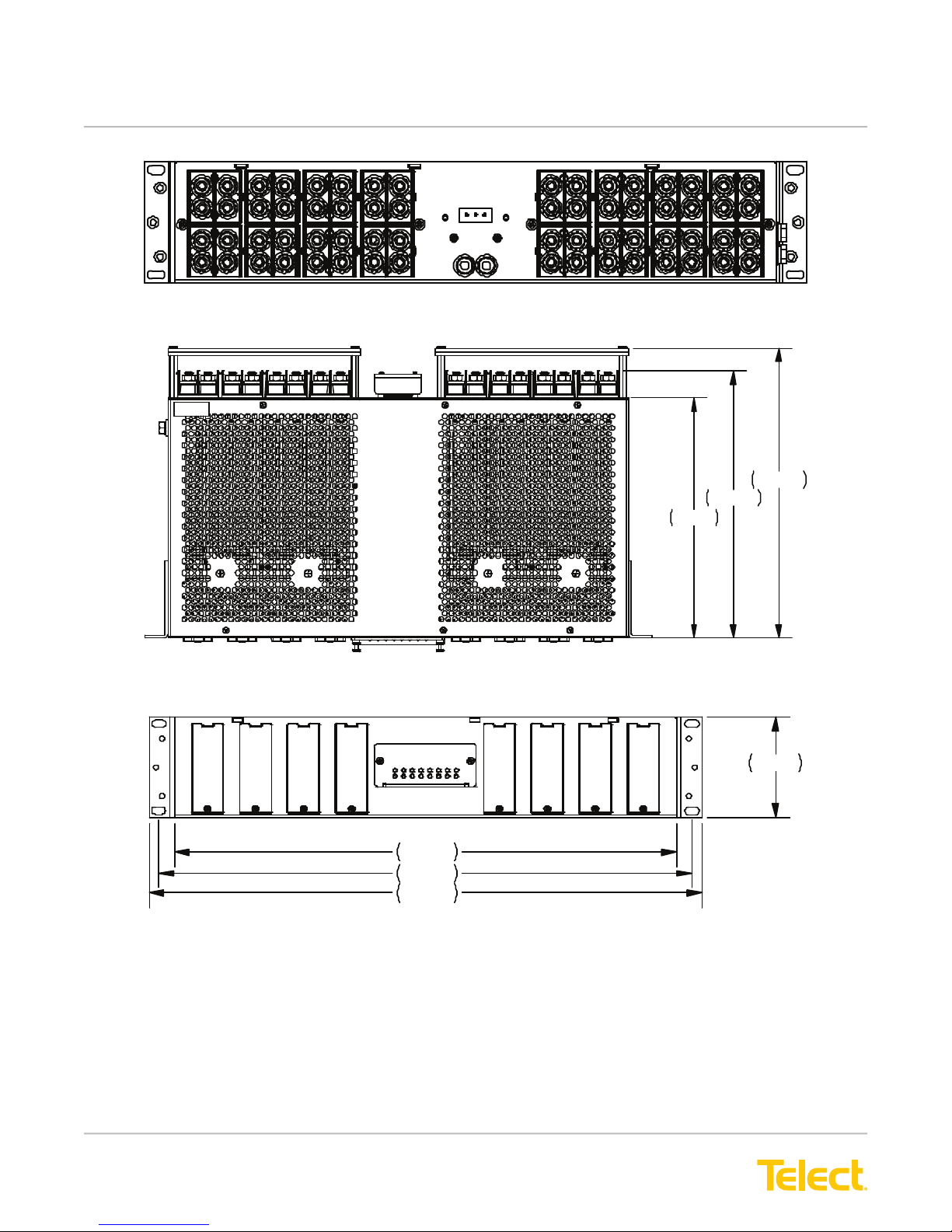
Rear View
10.840
10.000
9.000
Top View
3.470
17.250
18.312
19.000
Front View
Telect assumes no liability from the application or use of these products. Neither does Telect convey any license
under its patent rights or the patent rights of others. This document and the products described herein are subject
to change without notice.
© Telect, Inc., All Rights Reserved, 139695-3 A0
1.509.926.6000 :: telect.com
15
Page 18

Demarcation Fuse/Circuit Breaker Alarm Panel
Power :: Model 125DM08
This page intentionally left blank.
© Telect, Inc., All Rights Reserved, 139695-3 A0
1.509.926.6000 :: telect.com
16
 Loading...