

Page 1
Dual-Feed 200A 4/5 TPA/GMT Fuse Alarm Panel
Power :: 009-8005-0404 :: 009-8005-0404G :: 009-8005-0404L ::
009-1000-1033RE (End of Life June 30, 2015)
Installation Guide
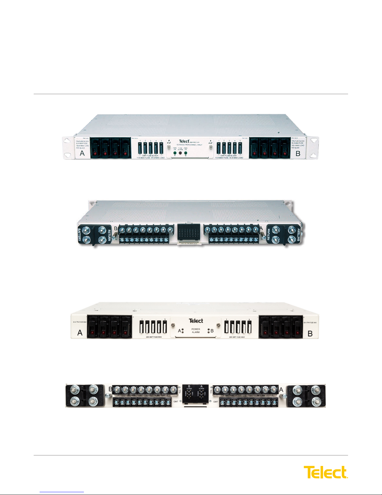
Fuse Alarm Panel - 009-8005-0404
Front view
Fuse Alarm Panel - 009-8005-0404
Rear view
Fuse Alarm Panel - 009-8005-0404G
Front view
Fuse Alarm Panel - 009-8005-0404G
Rear view
Applies to: 009-8005-0404, 009-8005-0404G, 009-8005-0404L, and 009-1000-1033RE (End of Life June 30, 2015)
© Telect, Inc., All Rights Reserved, 123518-9 A0
1.509.926.6000 :: telect.com
Page 2

Dual-Feed 200A 4/5 TPA/GMT Fuse Alarm Panel
Power :: 009-8005-0404 :: 009-8005-0404G :: 009-8005-0404L
Table of Contents
1.1 Specications ..................................................................................................................1
1.2 Important Installation Guidelines ..................................................................................... 4
1.3 Installation .......................................................................................................................5
1.4 Accessories ................................................................................................................... 13
1.4.1 Compression Lugs ................................................................................................. 14
1.5 Schematic Drawing .......................................................................................................15
1.6 Assembly Drawings .......................................................................................................16
List of Figures
Figure 1 - Model 009-8005-0404 ..........................................................................................1
Figure 2 - Model 009-8005-0404G ........................................................................................1
Figure 3 - Bracket Orientation ............................................................................................... 5
Figure 4 - Rack Mounting ...................................................................................................... 5
Figure 5 - Ground Lug Connection........................................................................................ 6
Figure 6 - Input Lugs .............................................................................................................6
Figure 7 - Disengaging a TPA Fuse Holder ........................................................................... 7
Figure 8 - Alarm Indicators 009-8005-0404 ..........................................................................7
Figure 9 - Alarm Reference Card and Terminals 009-8005-0404 ..........................................8
Figure 10 - Alarm Indicators 009-8005-0404G ......................................................................9
Figure 11 - Power Alarm Terminals 009-8004-0404G ...........................................................9
Figure 12 - TPA Output Lug Connections ............................................................................ 10
Figure 13 - GMT Output Lug Connections .......................................................................... 10
Figure 14 - Installing TPA Fuses .......................................................................................... 11
Figure 15 - Installing GMT Fuses ........................................................................................ 11
Figure 16 - Designation Card .............................................................................................. 12
© Telect, Inc., All Rights Reserved, 123518-9 A0
1.509.926.6000 :: telect.com
II
Page 3
Dual-Feed 200A 4/5 TPA/GMT Fuse Alarm Panel
Power :: 009-8005-0404 :: 009-8005-0404G :: 009-8005-0404L
Telect’s dual 200A fuse alarm panels provide power
protection for a variety of telecommunications
equipment.
Panels include 8 TPA output fuse holders (4 per side)
and 10 GMT fuse holders (5 per side). Sides A and
B in model 009-8005-0404 and 009-8005-0404L are
electrically independent except for the replaceable
alarm card. Sides A and B in model 009-8005-0404G
are electrically independent including the replaceable
alarm card. Both models contain power and alarm
LEDs for both feeds. Also included are fuse alarm and
power-fail relay terminals for external indicators. Models
are NEBS Level 3 certied and listed by UL for the USA
and Canada.
Model 009-1000-1033RE is equivalent to model 009-8005-0404L with respect to specications and functionality.
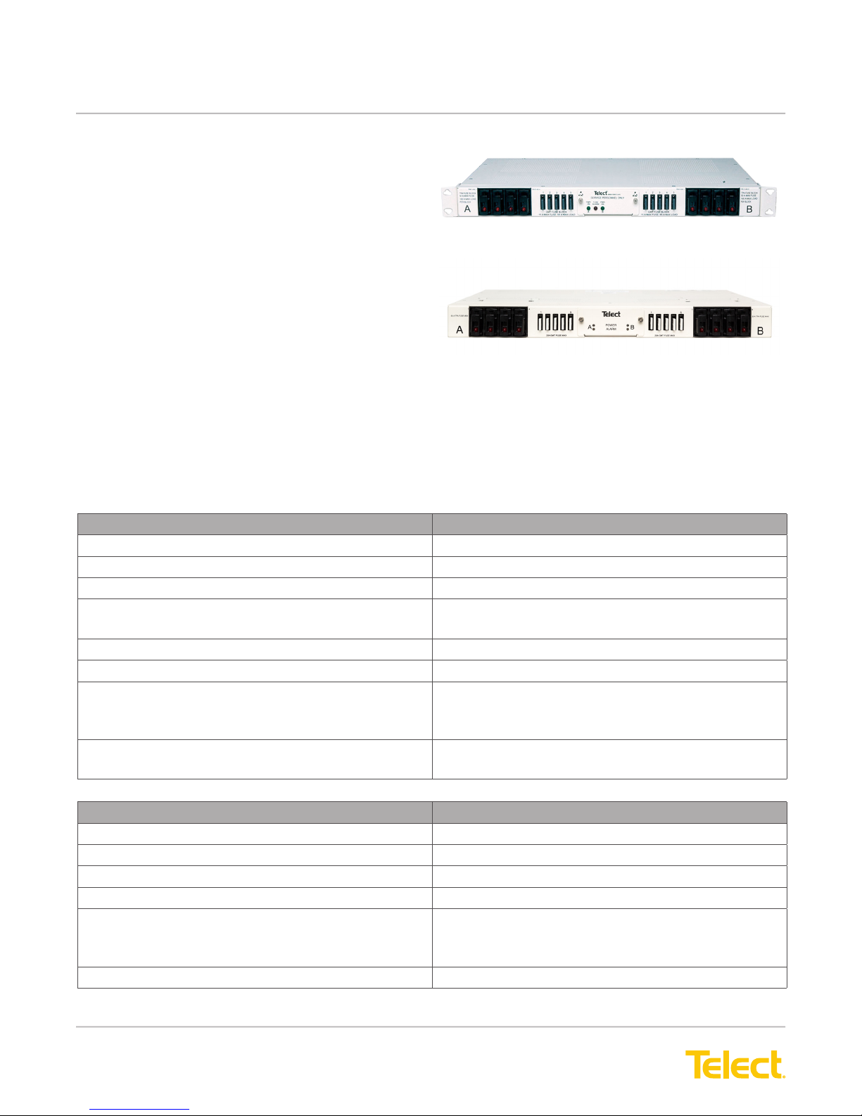
Figure 1 - Model 009-8005-0404
Figure 2 - Model 009-8005-0404G
1.1 Specications
Inputs Specications
Nominal Voltage ±24Vdc, -48Vdc
Max. input load rating 200A per side
Nominal power loss at full load 70W per side @ 9600W full load per side (200Ax48V)
Percentage of full load power dissipation at nominal
voltage
Max. input interrupt device 250A
Short circuit withstand rating 5000A; GMT 450A
Input terminal studs (with split ring lock washers &
nuts) for dual-hole compression lugs
Input Wire Size #8 to #4/0 AWG (depends on input interrupt device);
TPA Outputs Specications
Max. TPA Output Fuse (ea.) 50A
Max. TPA Output Load (ea.) - continuous 40A
Max. Total TPA Output Load 160A per side
Short circuit withstand rating 5000A
TPA Output Terminal Studs with nuts 16, single, #10 - 32 studs (max. lug width of 0.46 in.
TPA Output Wire Size #18 to #6 AWG (depends on output fuse rating)
Less than 1%
Dual 1/4"-20 studs on 3/4 in. centers.
(Torque nut [using 7/16 in. or 12 mm socket] to
~45 in.-lb [~5 N•m])
1" lug width
[1.17 cm]). Torque nut (using 3/8 in. or 10 mm socket) to
~20 in.-lb (~2.3 N•m)
© Telect, Inc., All Rights Reserved, 123518-9 A0
1.509.926.6000 :: telect.com
1
Page 4
Dual-Feed 200A 4/5 TPA/GMT Fuse Alarm Panel
Power :: 009-8005-0404 :: 009-8005-0404G :: 009-8005-0404L
GMT Outputs Specications
Max. GMT Output Fuse (ea.)
009-8005-0404 and 009-8005-0404L
009-8005-0404G
Max. GMT Output Load (ea.) - continuous
009-8005-0404 and 009-8005-0404L
009-8005-0404G
Max. Total GMT Output Load 65A per side
Short circuit withstand rating 450A
GMT Output Terminal (wire binding) 20, #6 panhead screws (max lug width of .32 in.
GMT Output Wire Size #20 to #12 AWG (depends on output fuse rating)
Grounding Specications
Earth GND Terminal Studs (with split ring lock
washers & hex nuts) for dual-hole compression lug
Ground Wire Size Up to #4 AWG (depends on input interrupt device)
15A
20A
10.5A
14A
[.81 cm])
Dual 1/4"-20 threaded holes on 5/8 in. (1.59 cm)
centers. Torque supplied bolt (using 7/16 in. or 12 mm
socket) to 45 in.-lb (5 N•m)
Alarms Specications
Alarm Relay Contacts 2A @ 30 Vdc
0.6A @ 60 Vdc
Max. Alarm Card Power Rating @20V: 85 mA (1.70W)
@24V: 103 mA (2.47W)
@27V: 109 mA (2.94W)
@30V: 112 mA (3.36W)
@42V: 123 mA (5.17W)
@48V: 128 mA (6.14W)
@56V: 135 mA (7.56W)
@60V: 139 mA (8.34W)
009-8005-0404 and 009-8005-0404L: 8W
009-8005-0404G: 2W
Alarm Wire Size #24 AWG, typ (#26 to #20 AWG)
Indicators Specications
INPUT POWER LEDs (Green) Lights when power is applied to that feed
FUSE ALARM LED (Red) Lights if any GMT fuse blows
© Telect, Inc., All Rights Reserved, 123518-9 A0
1.509.926.6000 :: telect.com
2
Page 5
Dual-Feed 200A 4/5 TPA/GMT Fuse Alarm Panel
Power :: 009-8005-0404 :: 009-8005-0404G :: 009-8005-0404L
Dimensions Specications
Nominal, without brackets*
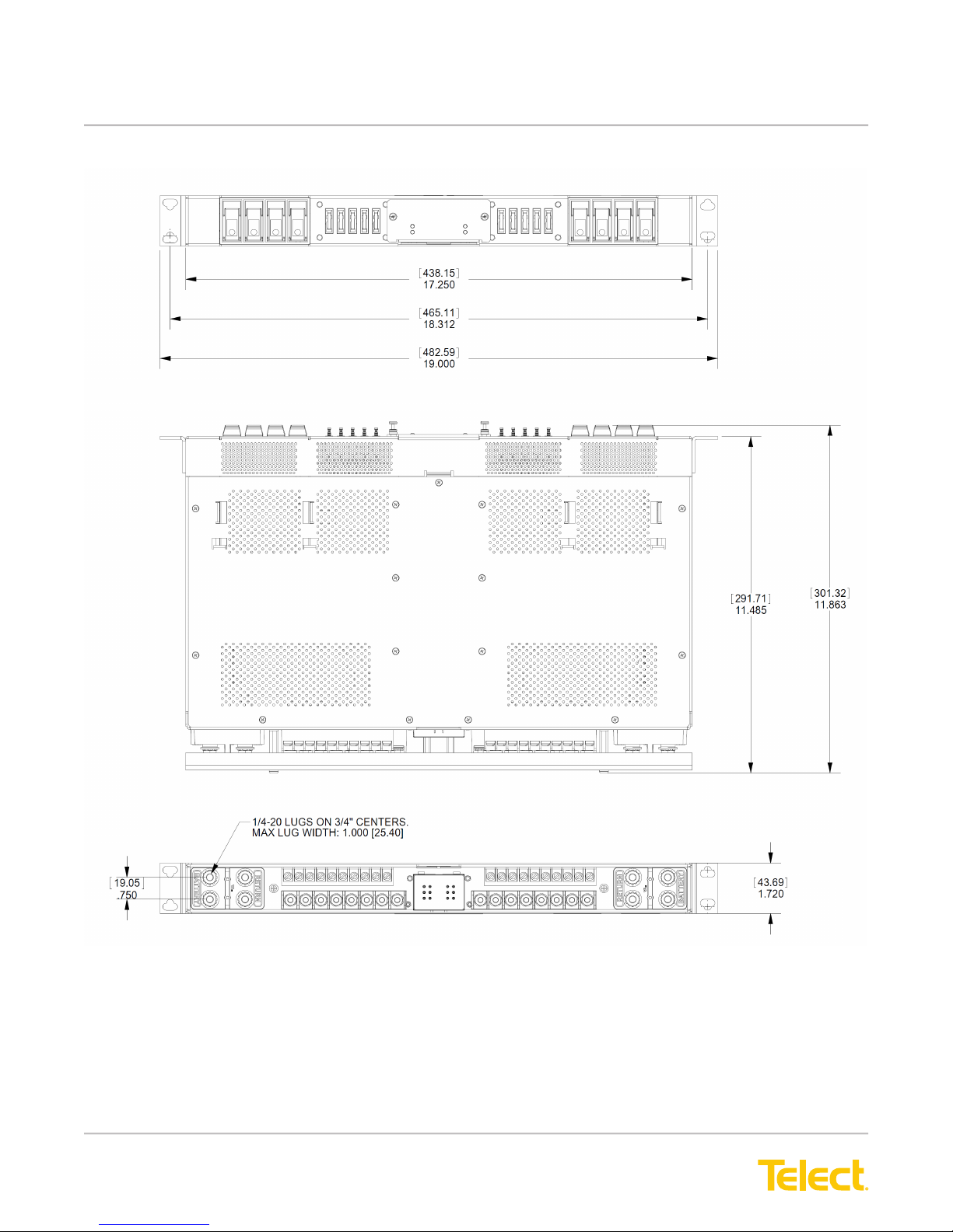
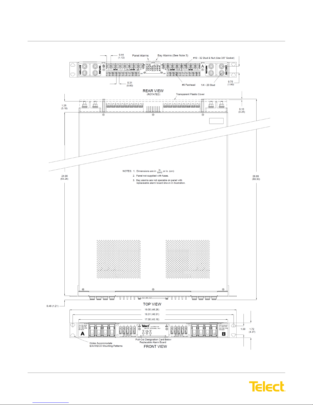
* See pages 16-18 for exact dimensions
Weight Specications
Weight, without packaging ~14 lb (~6 kg)
Weight, shipping ~15 lb (~7 kg)
Environment Specications
Operating Temperature Range (at 200A)
009-8005-0404
009-8005-0404G
009-8005-0404L
Width: 17.25 in. (43.82 cm)
Height: 1.75 in. (4.44 cm)
Depth: 10 in (25.40 cm)
25 in. (63.50 cm) - model 009-8005-0404L
~24 lb (~11 kg) - model 009-8005-0404L
~26 lb (~12 kg) - model 009-8005-0404L
-10°C (14°F) to 55°C (131°F)
-5°C (12°F) to 50°C (122°F)
-10°C (14°F) to 35°C (95°F) at 225A
Hardware is included for ush or extended mounting in 19" or 23" relay racks. Due to it’s depth and weight,
mounting rails are recommended for model 009-8005-0404L. Visit our website to order Telect accessories and
replaceable parts: output fuses (3A-50A TPA; 1⁄4A-20A GMT), dummy fuses, lugs, ETSI mounting kit, and more.
© Telect, Inc., All Rights Reserved, 123518-9 A0
1.509.926.6000 :: telect.com
3
Page 6

Dual-Feed 200A 4/5 TPA/GMT Fuse Alarm Panel
Power :: 009-8005-0404 :: 009-8005-0404G :: 009-8005-0404L
ALERT
!
ALERT! Only qualied personnel may install and maintain this product. Verify that all connections
meet requirements specied in local electric codes or operating company guidelines before supplying
power. Protect this equipment with a fuse or breaker sufficient to interrupt power levels specied on
preceding page.
This product must be installed within a restricted access location where access is through the use of
a tool, lock and key, or other means of security, and is controlled by the authority responsible for the
location.
1.2 Important Installation Guildelines
• Elevated Operating Ambient Temperature :: If you install the rack in a closed or multi-unit rack assembly, the
operating ambient temperature of the rack environment may be greater than room ambient. Therefore, take care
to install the equipment in an environment compatible with the maximum operating temperature.
• Reduced Air Flow :: Installation of the equipment in a rack should be such that the amount of air ow required
for safe operation of the equipment is not compromised.
• Mechanical Loading :: Mounting of the equipment in the rack should be such that a hazardous condition is not
achieved due to uneven mechanical loading.
• Circuit Overloading - Give consideration to the connection of the equipment to the supply circuit and the effect
that overloading of the circuits might have on overcurrent protection and supply wiring. Use appropriate consideration for equipment nameplate ratings when addressing this concern.
• Reliable Earthing :: Maintain reliable earthing of rack-mounted equipment. Pay particular attention to supply
connections other than direct connections to the branch circuit (e.g., use of power strips).
• Disconnect Device :: Incorporate a readily accessible disconnect device in the building installation wiring.
Inspection
Please read and understand all instructions before starting installation. If you have questions, contact Telect
Technical Support at [email protected] or call 1.509.926.6000.
When you receive the equipment, carefully unpack it and compare it to the packaging list. Please report any
defective or missing parts to Telect Quality at [email protected] or call 1.509.926.6000.
Telect is not liable for transit damaged. If the product is damaged, please report it to the carrier and contact
Telect Quality.
© Telect, Inc., All Rights Reserved, 123518-9 A0
1.509.926.6000 :: telect.com
4
Page 7
Dual-Feed 200A 4/5 TPA/GMT Fuse Alarm Panel
WARNING
!
!
Power :: 009-8005-0404 :: 009-8005-0404G :: 009-8005-0404L
1.3 Installation
Panel brackets provide ush or extended EIA or WECO mounting in a 19 or 23 in. rack. The panel is congured at
the factory for 1 in. extended mounting in a 19 in. rack.
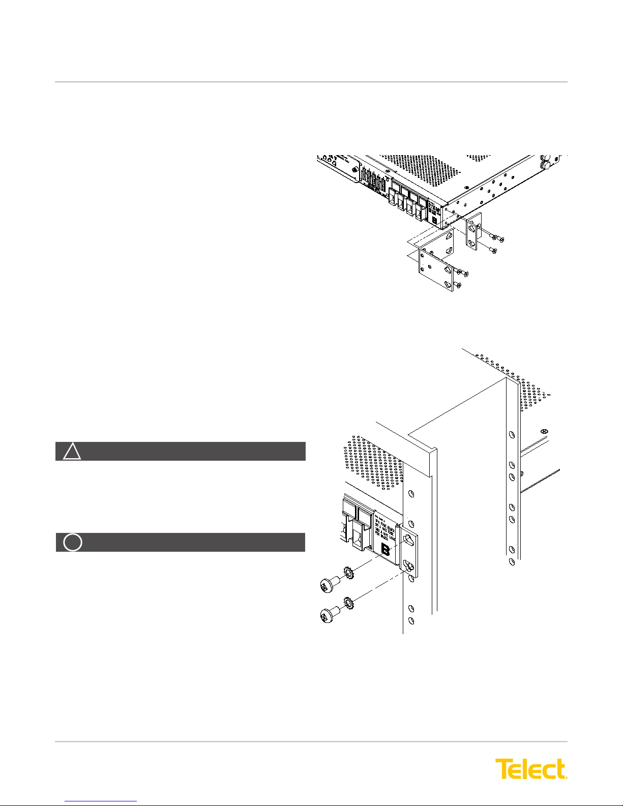
1. If necessary, remove three screws and
reposition/re-align the brackets on the sides of the
distribution panel, as shown in Figure 3.
2. Locate an unused rack position and mount the
panel using four screws and lock washers provided,
as shown in Figure 4. (Place the mounting panel as
high as possible on the rack.) Due to the depth and
weight of model 009-8005-0404L, mounting rails
should be used to support the mounted panel in the
rack.
3. Tighten the screws to 35 in.-lb. (4.29 N•m).
4. Loosen (you need not remove) two screws securing
the rear terminal cover on the back of the panel.
Figure 3 - Bracket Orientation
5. Remove the cover.
6. Use a listed (approved) crimping tool to attach a
listed (approved), dual-hole compression lug onto a
suitable ground wire. (Size of the ground depends
on input interruption device.)
WARNING! Failure to properly ground this
equipment can create hazardous conditions to
installation personnel and to the equipment.
ALERT
ALERT! Only use components and crimping tools
approved by agencies or certifying bodies
recognized in your country or region, such as
Underwriter’s Laboratories (UL), TUV, etc.
© Telect, Inc., All Rights Reserved, 123518-9 A0
1.509.926.6000 :: telect.com
Figure 4 - Rack Mounting
5
Page 8
Dual-Feed 200A 4/5 TPA/GMT Fuse Alarm Panel
Power :: 009-8005-0404 :: 009-8005-0404G :: 009-8005-0404L
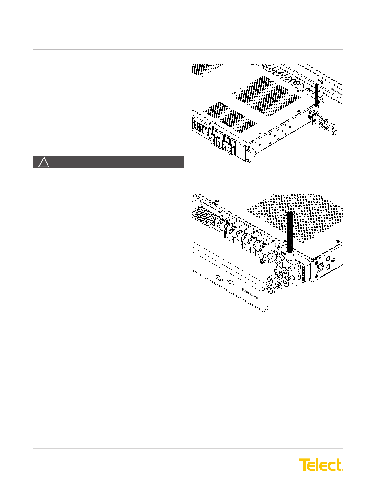
7. If required, lightly coat anti-oxidant on the lug and
grounding surface on the side of the panel.
8. Connect the lug using the 1⁄4"-20 bolt, split ring
washer and at washer provided, as shown in
Figure 5.
9. Tighten the bolt to 45 in.-lb. (5 N•m).
10. Make sure the input power is off (open breaker,
dummy fuse, or open fuse holder at power
distribution unit [PDU]) before connecting this
panel’s input cables to the PDU.
WARNING
!
WARNING! Before connecting the input power
cables, make sure the input power to the panel is
turned off.
11. For input wiring—wiring used as inputs to this
distribution panel—crimp dual-hole compression
lugs onto #8 AWG to #4/0 AWG copper wires.
Insulate lug barrels with UL94 V-0 rated heat-shrink
tubing.
12. Clean the terminals and lugs with a nonabrasive,
nonmetallic pad.
13. If required, lightly coat anti-oxidant on lugs and
input BATTERY and RETURN terminals.
14. Connect the lugs to input terminals on back of
panel, as shown in Figure 6.
15. Tighten the lugs to 45 in.-lb. (5 N•m).
Figure 5 - Ground Lug Connection
Figure 6 - Input Lugs
© Telect, Inc., All Rights Reserved, 123518-9 A0
1.509.926.6000 :: telect.com
6
Page 9
Dual-Feed 200A 4/5 TPA/GMT Fuse Alarm Panel
Power :: 009-8005-0404 :: 009-8005-0404G :: 009-8005-0404L
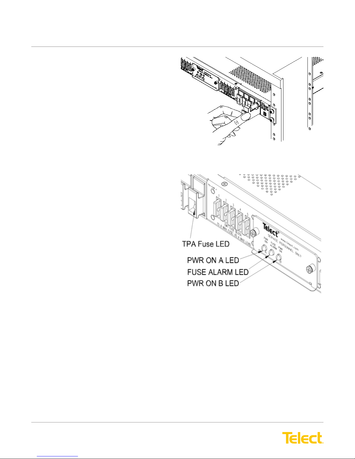
16. Make sure TPA and GMT fuse positions are
either empty or contain dummy fuses (phoney,
inoperative all-plastic slugs). If necessary, pull out
the TPA carrier about an inch from its holder to
disengage the TPA fuse, as shown in Figure 7.
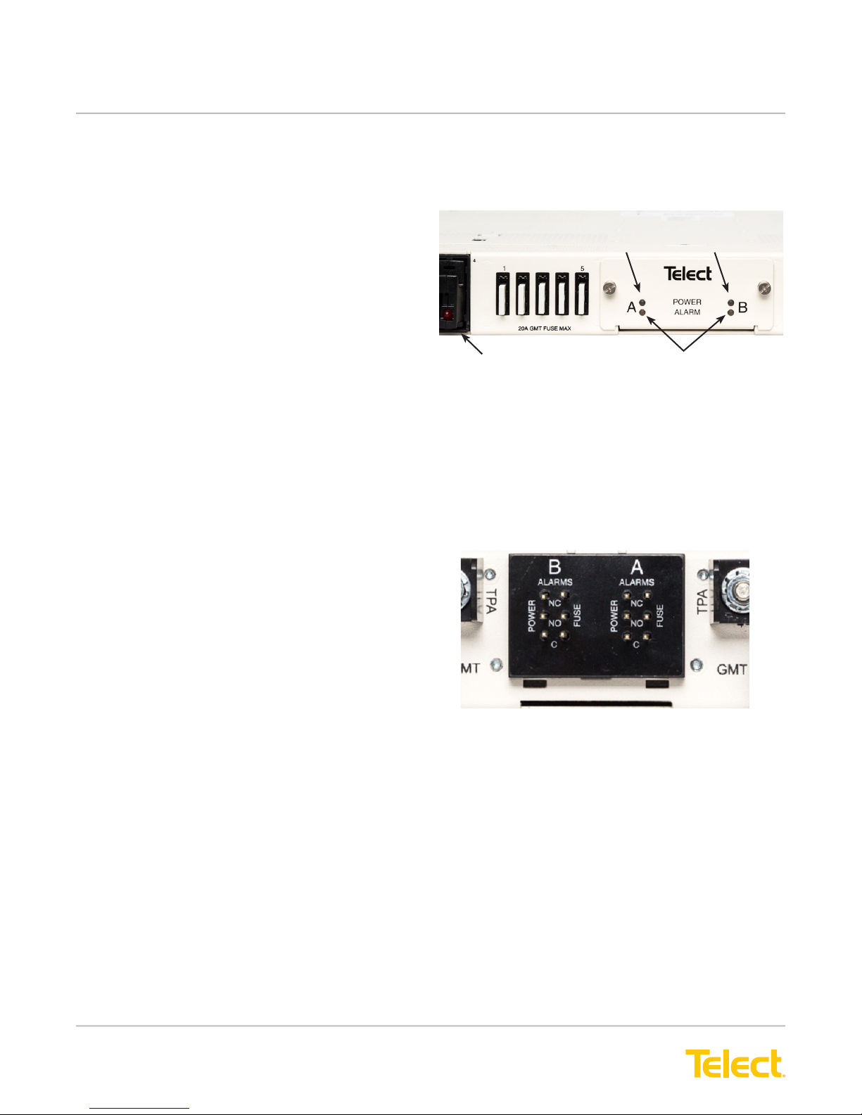
For 009-8005-0404 and 009-8005-0404L alarm indicators, continue at step 17.
For 009-8005-0404G alarm indicators, go to step 22.
1 7. Enable the fuse or breaker at PDU (250A max.)
to turn on Feed A to Side A and then check
voltage and polarity at input connectors of panel.
Also, check that,
• PWR ON A LED on front of panel turns on
(green). (See Figure 8 for location.)
• PWR ON B, FUSE ALARM, and TPA Fuse
LEDs must be off.
Figure 7 - Disengaging a TPA Fuse Holder
© Telect, Inc., All Rights Reserved, 123518-9 A0
1.509.926.6000 :: telect.com
Figure 8 - Alarm Indicators
009-8005-0404
7
Page 10
Dual-Feed 200A 4/5 TPA/GMT Fuse Alarm Panel
Power :: 009-8005-0404 :: 009-8005-0404G :: 009-8005-0404L
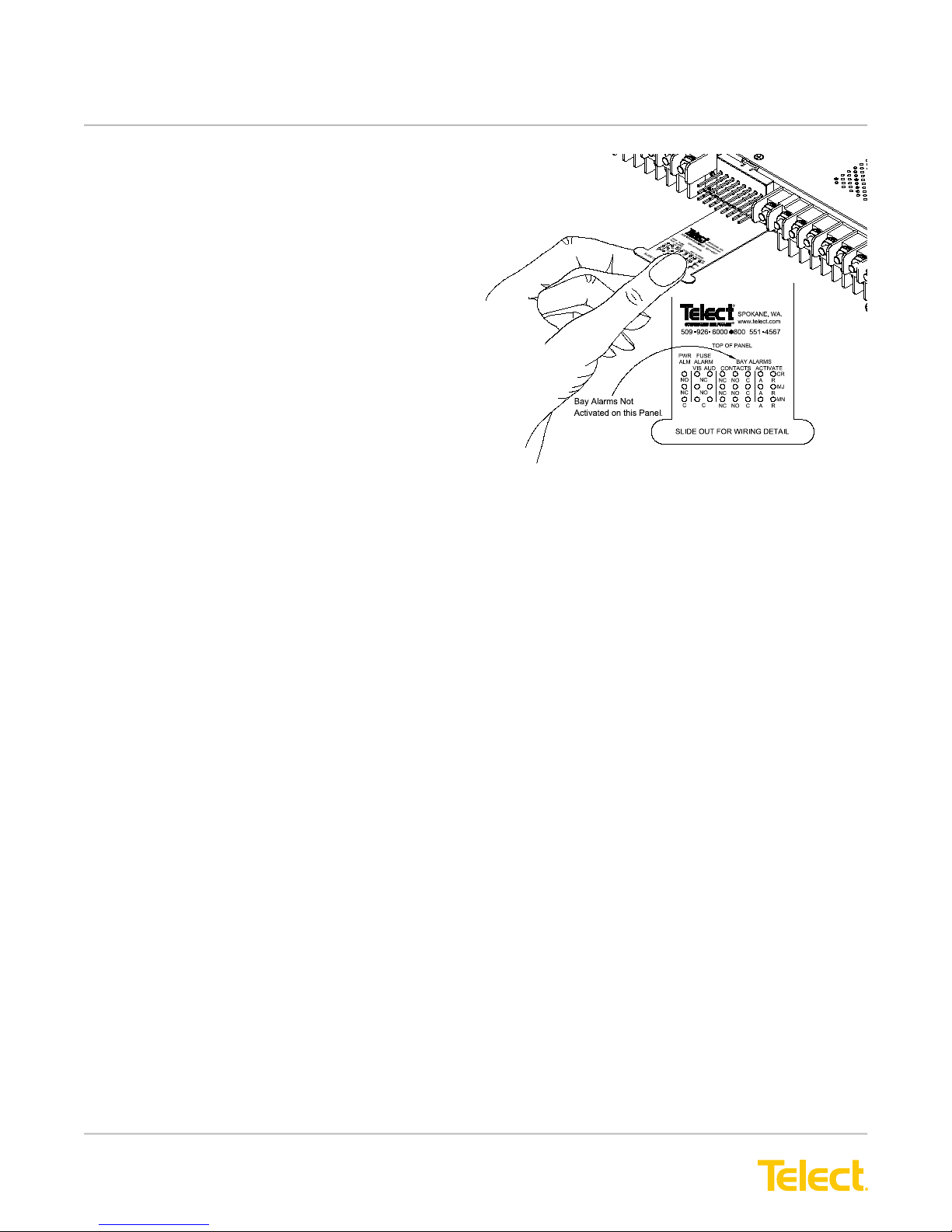
18. At the rear of the panel, pull to extend plastic
reference card below alarm terminals. (See
Figure 9.) With PWR ON A lit (normal
operation)—but with PWR ON B LED off
(failure operation)—test power-fail relay and
contacts at PWR ALM terminals on the rear of
the panel:
• Expect an open circuit (∞Ω) between
Terminals C and NC.
• Expect continuity (0Ω) between
Terminals C and NO.
19. Also, test the fuse alarm relay contacts at the
FUSE ALARM terminals on the rear of the panel.
For both the VIS (visual) and AUD (audible)
indicator contacts,
• Expect continuity (0Ω) between Terminals
C and NC.
• Expect an open circuit (∞Ω) between Terminals
C and NO.
Figure 9 - Alarm Reference Card and Terminals
009-8005-0404
20. Repeat Steps 17 through 20 to power up Side B.
PWR ON A and PWR ON B must both be lit.
2 1. With PWR ON A and B lit (normal operation),
test power-fail relay and contacts at PWR ALM
terminals on the rear of the panel:
• Expect continuity (0Ω) between Terminals
C and NC.
• Expect an open circuit (∞Ω) between Terminals
C and NO.
© Telect, Inc., All Rights Reserved, 123518-9 A0
1.509.926.6000 :: telect.com
8
Page 11
Dual-Feed 200A 4/5 TPA/GMT Fuse Alarm Panel
Power :: 009-8005-0404 :: 009-8005-0404G :: 009-8005-0404L
For 009-8005-0404 and 009-8005-0404L, continue at
step 24.
22. Enable the fuse or breaker at PDU (250A max.)
to turn on Feed A to Side A. Also enable fuse
or breaker at PDU 250A max.) to turn on Feed
B to Side B. Check voltage and polarity at input
connectors of panel. Also, check that,
• POWER ON A LED on front of panel turns on
(green).
• FUSE ALARM LED must be off.
• POWER ON B LED on front of panel turns on
(green).
• FUSE ALARM LED must be off.
(See Figure 10 for 009-8005-0404G alarm indicator
locations.)
TPA Fuse
Figure 10 - Alarm Indicators
Power A LED Power B LED
Fuse Alarm LED
009-8005-0404G
23. With PWR ON A LED lit (normal operation)—
and with PWR ON B LED lit (normal operation)—
test power-fail relay and contacts at PWR ALM
terminals on the rear of the panel:
• expect continuity (0Ω) between Terminals C
and NC.
• expect an open circuit (∞Ω) between Terminals
C and NO.
(See Figure 11 for 009-8005-0404G power alarm
terminals.)
For all panels, continue at step 24.
Figure 11 - Power Alarm Terminals
009-8005-0404G
© Telect, Inc., All Rights Reserved, 123518-9 A0
1.509.926.6000 :: telect.com
9
Page 12
Dual-Feed 200A 4/5 TPA/GMT Fuse Alarm Panel
Power :: 009-8005-0404 :: 009-8005-0404G :: 009-8005-0404L
24. Make sure none of the fuse positions contain
operable fuses.
25. For TPA output wiring, crimp single-hole lugs onto
one end of #18 to #6 AWG copper output wires,
as required by NEC. (Work with one output wire
at a time.)
26. Clean the panel terminals and lugs with a
nonabrasive, nonmetallic pad.
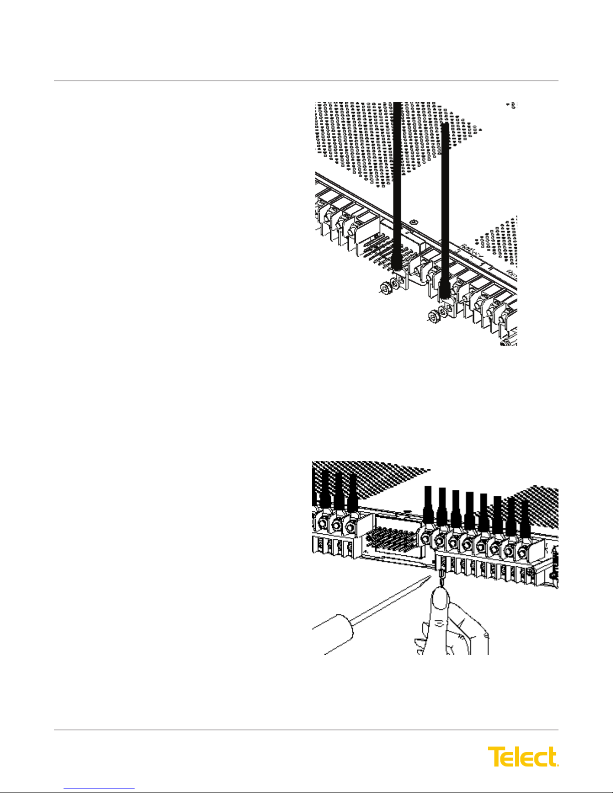
2 7. If required, lightly coat anti-oxidant on lugs and
output BATTERY and RETURN terminals, and
then connect lug to terminals, as shown in
Figure 12. (NEC species only one lug and load
at each output terminal.)
28. Tighten the nuts to 20 in.-lb. (~2.3 N•m).
29. Connect the other end of the output wire to load.
30. For GMT output wiring, use #20 to #12 AWG
copper wire. (Work with one wire at a time.) At
the panel end of the wire, either
• Crimp a single-hole ring or fork lug, as required
by NEC, or
• Strip 3/8 in. (1 cm) of insulation for a bare
wire connection.
Figure 12 - TPA Output Lug Connections
3 1. Clean the panel terminals and lug (if applicable)
with a nonabrasive, nonmetallic pad.
32. If required, lightly coat anti-oxidant on the lug/wire
and output BATTERY and RETURN terminals.
33. Connect to the terminals, as shown in Figure13.
(NEC species only one load at each output
terminal.)
34. Tighten the panhead screws to no more than
8 in.-lb. (~1 N•m).
35. Connect the other end of the output wire to load.
Figure 13 - GMT Output Lug Connections
© Telect, Inc., All Rights Reserved, 123518-9 A0
1.509.926.6000 :: telect.com
10
Page 13
Dual-Feed 200A 4/5 TPA/GMT Fuse Alarm Panel
Power :: 009-8005-0404 :: 009-8005-0404G :: 009-8005-0404L
ALERT
!
ALERT! GMT fuses have a small inherent
electrical resistance resulting in a small inherent
power loss. For this reason, the GMT fuse
manufacturer recommends that the load for GMT
fuses up to and including 7.5A not exceed 80% of
the fuse rating and that the load for GMT fuse sizes
between 10A and 20A not exceed 70% of the fuse
rating. For example, the load for a 15A GMT fuse
should not exceed 10.5A (15A x.70 = 10.5A).
36. Make sure the load devices are switched off and
then install the fuses:
NOTE: Under load, TPA modules are disconnect
devices only and must not be used to reconnect
power to enabled equipment loads. Reconnecting
a TPA module under power with an enabled load
may damage the TPA module.
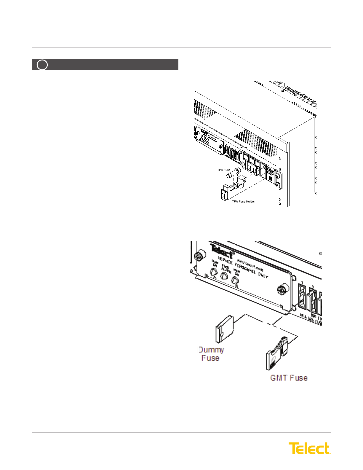
• For a TPA fuse, pull out the TPA fuse carrier
and insert the operable fuse, as shown in
Figure 14.
• For a GMT fuse, pull out the dummy fuse and
insert the operable fuse, as shown in Figure 15.
• Test the power and polarity at the input of each
equipment load.
Figure 14 - Installing TPA Fuses
© Telect, Inc., All Rights Reserved, 123518-9 A0
1.509.926.6000 :: telect.com
Figure 15 - Installing GMT Fuses
11
Page 14
Dual-Feed 200A 4/5 TPA/GMT Fuse Alarm Panel
Power :: 009-8005-0404 :: 009-8005-0404G :: 009-8005-0404L
3 7. If possible,
• Temporarily replace one of the operable TPA
fuses with a blown fuse to check that the FUSE
ALARM and the TPA Fuse LEDs light red. Also,
check the FUSE ALARM terminals on the rear
of the panel:
− Expect an open circuit (∞Ω) between Terminals
C and NC.
− Expect continuity (0Ω) between Terminals
C and NO.
Re-install operable TPA fuse before proceeding.
• Likewise, replace one of the operable GMT fuses
with a blown fuse to verify that the FUSE ALARM
LED and FUSE ALARM terminals are also as
specied above.
Re-install the operable GMT fuse before
proceeding.
38. If desired, connect the remote external
audio/visual alarm indicator wires (solid or tinned
wires, #26 to #20 AWG) to the PWR ALARM and
FUSE ALARM terminals.
39. Carefully re-install the rear cover.
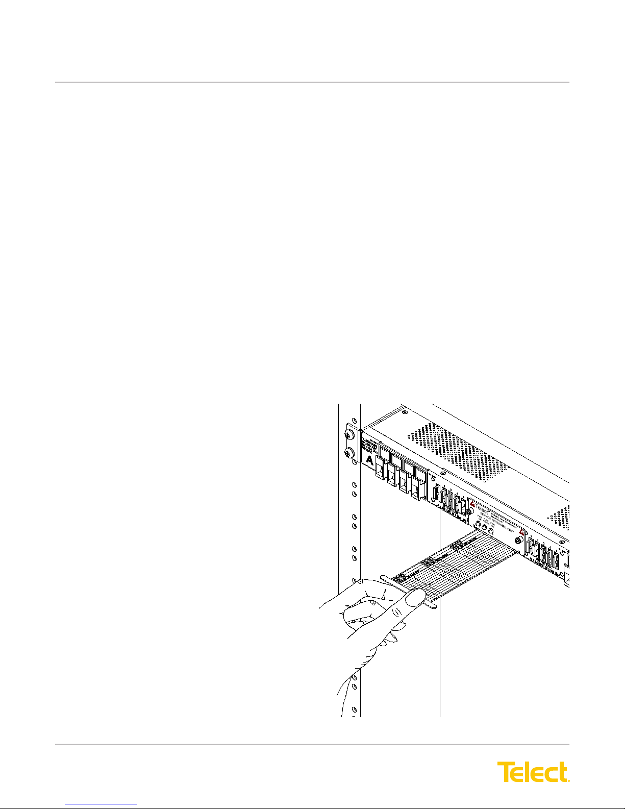
40. Record TPA and GMT output destinations on the
pull-out designation card below the front panel
LEDs, as shown in Figure 16.
4 1. Turn on equipment loads one at a time to verify
proper operation of loads.
© Telect, Inc., All Rights Reserved, 123518-9 A0
1.509.926.6000 :: telect.com
Figure 16 - Designation Card
12
Page 15
Dual-Feed 200A 4/5 TPA/GMT Fuse Alarm Panel
WARNING
!
Power :: 009-8005-0404 :: 009-8005-0404G :: 009-8005-0404L
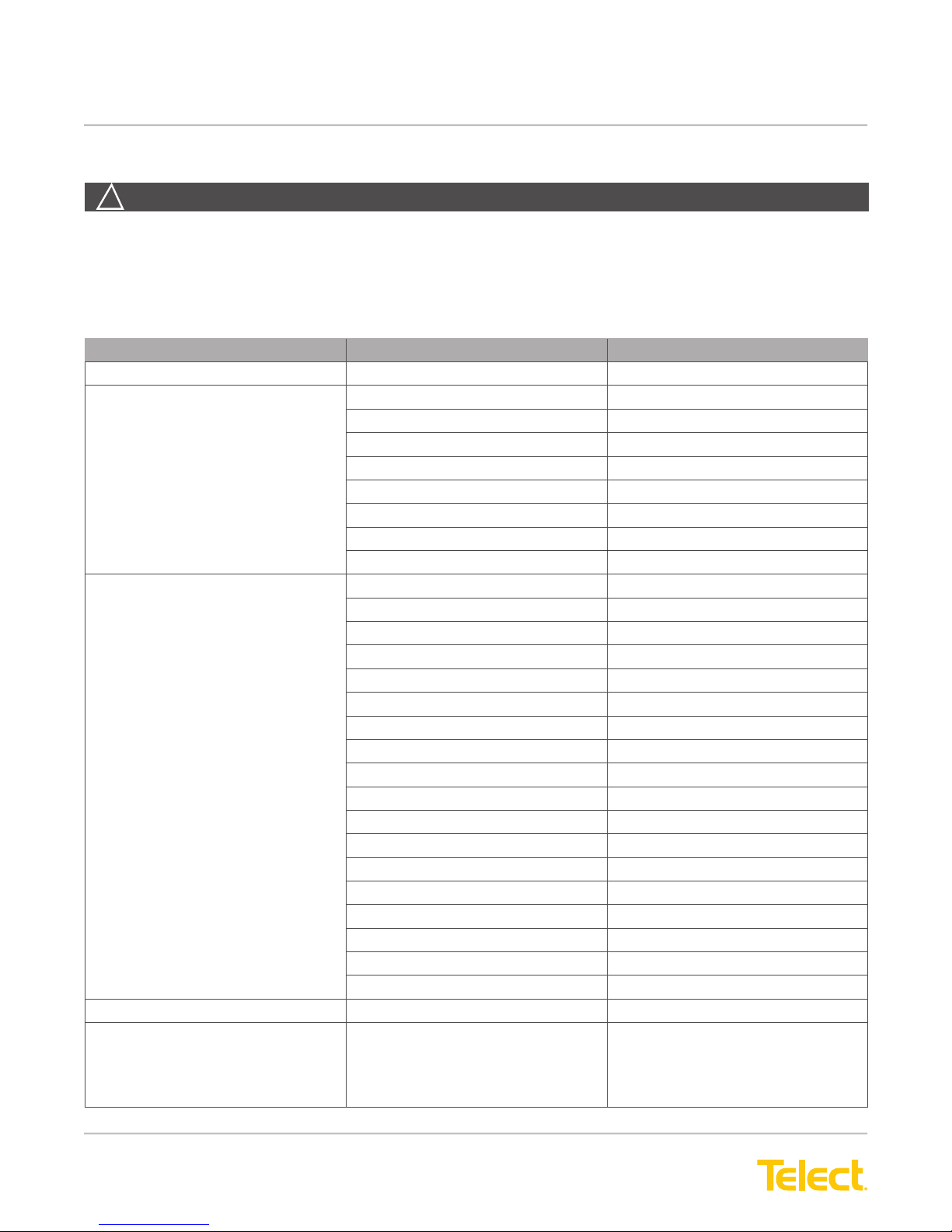
1.4 Accessories
WARNING! Use only UL-listed fuses or UL-recognized component secondary protection devices.
The following lists optional and replacement items for the panel. For selecting conductors, please refer to Wire
Sizing & Label Convention Chart (Telect Part No. 117995) included with your panel.
Item Description Part Number
TPA Fuses 5A 124818
10A 124819
15A 124820
20A 124821
25A 125244
30A 122734
40A 122738
50A 122739
TPA Fuse Holder 146010
GMT Fuses 1⁄2A Red (RED) 004001
3⁄4A Brown (BRN) 004008
1A Gray (GRY) 100991
1 1/3A White (WHT) 004006
1 1⁄2A White/Yellow (WHT/YEL) 004011
2A Orange (ORN) 004002
2 1/2A Orange/White (ORN/WHT) 130783
3A Blue (BLU) 004012
3 1/2A White/Blue (WHT/BLU) 130782
4A White/Brown (WHT/BRN) 004013
5A Green (GRN) 004014
71⁄2A Black/White (BLK/WHT) 004010
10A Red/White (RED/WHT) 004015
12A Yellow/Green (YEL/GRN) 102287
15A Red/Blue (RED/BLU) 102288
20A Green/White (GRN/WHT) 127240RC
Dummy, Phoney, Plastic Slug 132748
Safety Covers 116915
Replacement Accessories Rear Cover 122415
Alarm Card
009-8005-0404
009-8005-0404G
009-8005-0404L
400497
400802 + 746
400437
© Telect, Inc., All Rights Reserved, 123518-9 A0
1.509.926.6000 :: telect.com
13
Page 16
Dual-Feed 200A 4/5 TPA/GMT Fuse Alarm Panel
Power :: 009-8005-0404 :: 009-8005-0404G :: 009-8005-0404L
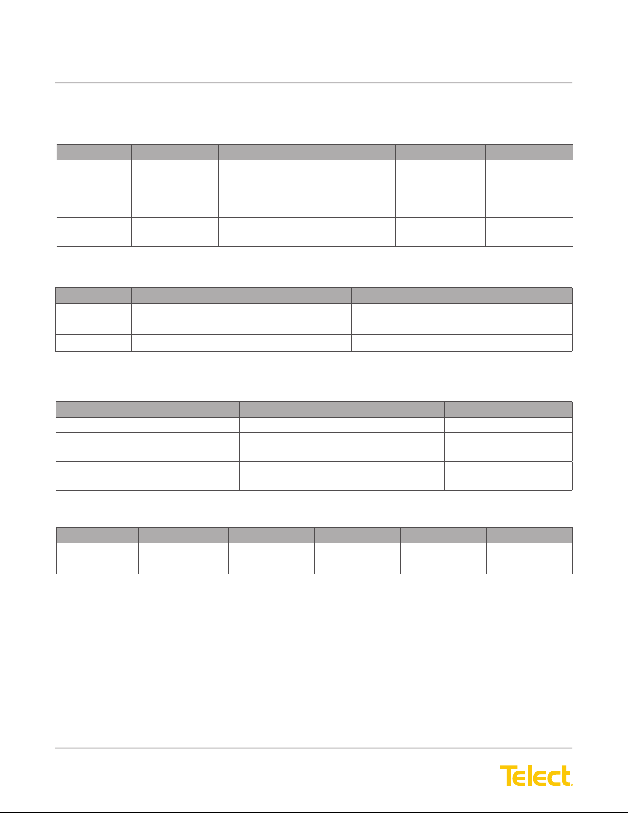
1.4.1 Compression Lugs
Table 1 - Input Power Lugs (1⁄4 in. Dual Holes on 3⁄4 in. Centers, Uninsulated)
Item 2 AWG 1 AWG 1/0 AWG 2/0 AWG 3/0 AWG
T&B 54208-0416
(Die Code 37)
Burndy YA2CL2TC14 E2
(Die Code 10)
Panduit LCD2-14B-Q
(Die Code 33)
Table 2 - Ground Lugs (1⁄4 in. Dual Holes on 5/8 in. Centers, Uninsulated)
Item 6 AWG 4 AWG
T & B 54205 (Die Code 24) 54206 (Die Code 29)
Burndy YA6CL2TC14 (Die Code 7) YA4CL2TC14 (Die Code 8)
Panduit LCD6-14A-L (Die Code 24) LCD4-14A-L (Die Code 29)
YA1CL2TC14E 2
(Die Code 11)
LCD1-12B-E
(Die Code 37)
54255-0416
(Die Code 42)
YA25L2TC14E2
(Die Code 12)
LCD1/0-14B-X
(Die Code 42)
54210-0416
(Die Code 45)
YA26L2TC14E2
(Die Code 13)
LCD2/0-14B-X
(Die Code 45)
54211UB-0416
(Die Code 50)
YA27L2TC14E2
(Die Code 13)
LCD3/0-14B-X
(Die Code 50)
Table 3 - TPA Output Ring Lugs
(#10 Screw Terminals, Nylon Insulated Except Where Noted)
Item 14 AWG 12 AWG 10 AWG 8 AWG
AMP 36160 35109 35109 324043
Burndy YAE12NBOX YAE12NBOX YAV10BOX YA8CLBOX (Uninsulated)
(Die Code 21)
Panduit LCA10-10-L LCA10-10-L LCA10-10-L LCA8-10-L (Uninsulated)
(Die Code 21)
Table 4 - GMT Output Ring Lugs (#6 Screw Terminals, Nylon Insulated)
Item 26 AWG 22 AWG 20 AWG 16 AWG 14 AWG
AMP 152658
Burndy YAE22N66FBOX YAE18N25BOX YAE14N76FBOX YAE12N1BOX
© Telect, Inc., All Rights Reserved, 123518-9 A0
1.509.926.6000 :: telect.com
14
Page 17
Dual-Feed 200A 4/5 TPA/GMT Fuse Alarm Panel
D
D
Power :: 009-8005-0404 :: 009-8005-0404G :: 009-8005-0404L
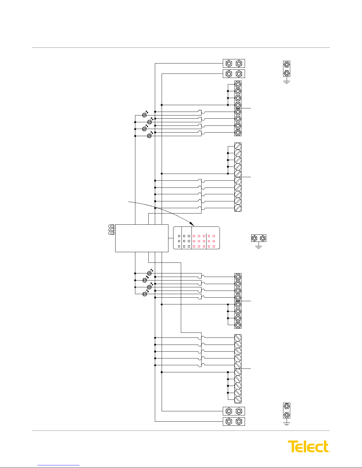
1.5 Schematic Drawing
Panel is not shipped with operable bay alarms.
TPA/GMT FUSE ALARM
PWR A
PWR B
TPA FUSE
HOLDER
LEDS
REMOVABLE ALARM CARD
PWR
ALARM
NO
NC
C
FUSE
ALARM
NC
NO
C
NC NOCCAARR
NC
BAY ALARMS
CONTACTS ACTIVATE
NO
BATT
INPUT A
RTN
TPA OUTPUT
RTN A
1
2
TPA OUTPUT
3
BATT A
4
GMT OUTPUT
RTN A
5
4
3
GMT OUTPUT
BATT A
2
1
CR
MJ
MN
C GND
C GN
© Telect, Inc., All Rights Reserved, 123518-9 A0
1.509.926.6000 :: telect.com
TPA FUSE
HOLDER
LEDS
15
1
2
TPA OUTPUT
3
4
TPA OUTPUT
5
4
GMT OUTPUT
3
2
1
GMT OUTPUT
RTN
BATT
BATT B
RTN B
BATT B
RTN B
INPUT B
C GN
Page 18
Dual-Feed 200A 4/5 TPA/GMT Fuse Alarm Panel
#10 - 32 Stud & Nut (Use 3/8" Socket)
1/4 - 20 Stud
#6 Panhead
NOTES:
1. Dimensions are in or in. (cm)
(cm)
in.
2. Panel not supplied with fuses.
REAR VIEW
(ROTATED)
TOP VIEW
FRONT VIEW
Universal Bracket Reversed for 23" Rack
Holes Accommodate
EIA/WECO Mounting Patterns
Pull-Out Designation Card Below
Replacable Alarm Board
1.72
(4.37)
1.00
(2.54)
23.00 (58.42)
22.31 (56.67)
19.00 (48.26)
18.31 (46.51)
17.25 (43.82)
11.86
(30.14)
0.10
(0.25)
1.00
(2.54)
2.00
(5.08)
1.00
(2.54)
0.39 (0.98)
10.01
(25.42)
1.15
(2.92)
T
P
A
P
A
T
GMT GMT
0.75
(1.90)
0.46
(1.17)
0.32
(0.81)
1/4 - 20 Hexhead Bolt
(Use 7/16" Socket)
0.625
(1.59)
SIDE VIEW
(DETAIL)
1.00
[2.54]
Lug width
Power :: 009-8005-0404 :: 009-8005-0404G :: 009-8005-0404L
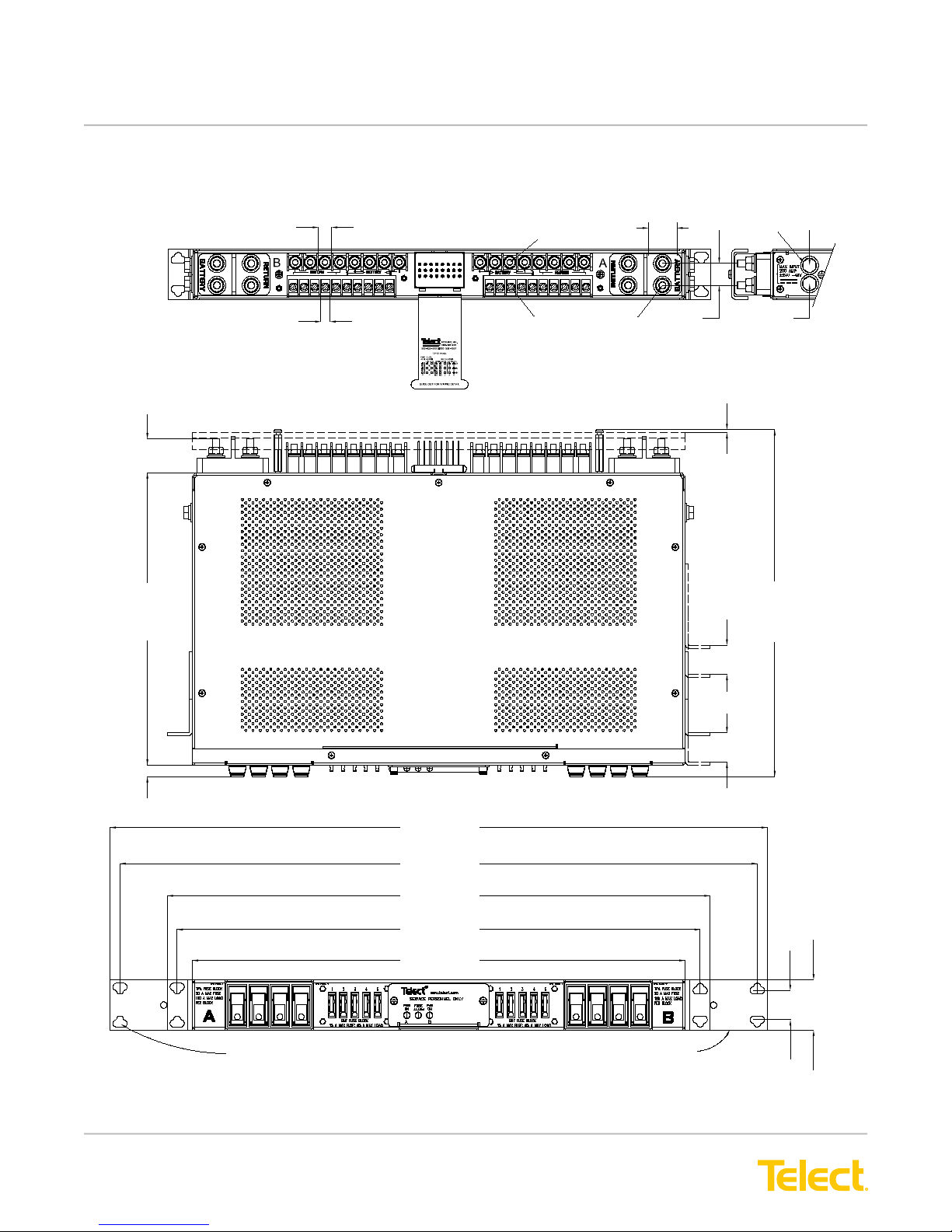
1.6 Assembly Drawings
Applies to: 009-8005-0404
© Telect, Inc., All Rights Reserved, 123518-9 A0
1.509.926.6000 :: telect.com
16
Page 19
Dual-Feed 200A 4/5 TPA/GMT Fuse Alarm Panel
Power :: 009-8005-0404 :: 009-8005-0404G :: 009-8005-0404L
Applies to: 009-8005-0404G
© Telect, Inc., All Rights Reserved, 123518-9 A0
1.509.926.6000 :: telect.com
17
Page 20
Dual-Feed 200A 4/5 TPA/GMT Fuse Alarm Panel
Power :: 009-8005-0404 :: 009-8005-0404G :: 009-8005-0404L
Applies to: 009-8005-0404L and 009-1000-1033RE
© Telect, Inc., All Rights Reserved, 123518-9 A0
1.509.926.6000 :: telect.com
18
Page 21

Dual-Feed 200A 4/5 TPA/GMT Fuse Alarm Panel
Power :: 009-8005-0404 :: 009-8005-0404G :: 009-8005-0404L
Telect assumes no liability from the application or use of these products. Neither does Telect convey any license
under its patent rights or the patent rights of others. This document and the products described herein are subject
to change without notice.
© Telect, Inc., All Rights Reserved, 123518-9 A0
1.509.926.6000 :: telect.com
19
Page 22

Dual-Feed 200A 4/5 TPA/GMT Fuse Alarm Panel
Power :: 009-8005-0404 :: 009-8005-0404G :: 009-8005-0404L
© Telect, Inc., All Rights Reserved, 123518-9 A0
1.509.926.6000 :: telect.com
20
 Loading...