

Lee’s Hi-tech Enterprise. Co., Ltd.
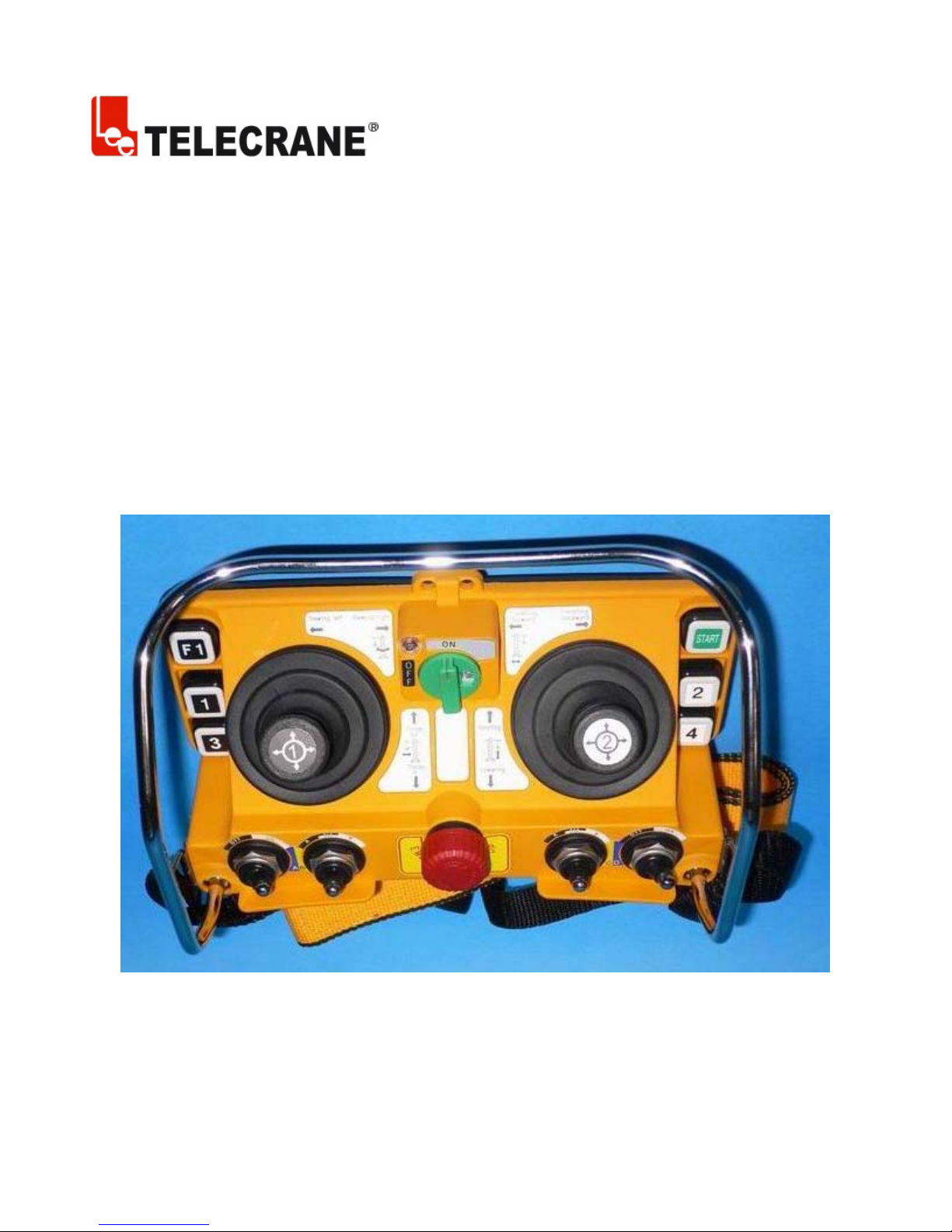
F25-60 Industrial Remote Controller

F25 -60 Operating Instructions
Warranty
Lee’s Hi-Tech Enterprises Co., Ltd. guarantees that this product meets its published specifications at
the time of shipment from the factory. Under proper installation it should work as expected.
Warranty Period
This equipment is warranted against defects in material and manufacturing for a period of one year
from the date of shipment. During the warranty period, TELECRANE is responsible for necessary
repairs as long as the product can be proved to be defective.
For warranty service or repair this product must be returned to a service facility designated by
TELECRANE. Buyer will pay shipping charges to TELECRANE while TELECRANE will pay return
shipping charges.
Excluded Items
This warranty does not include consumptive parts such as batteries, fuses, buttons, relays. Also this
warranty does not cover damages caused by improper installation, improper or insufficient
maintenance, unauthorized modification, improper operation, ignorance of environmental
specifications, or improper software setting.
Remarks
No other warranty is expressed or implied, except for the above mentioned.◎
The remedies provided herein are the bu◎ yer’s sole and exclusive remedies. TELECRANE shall not
be liable for any direct, indirect, special, incidental or consequential damages.
Attention
1. Never dismantle the equipment by any unauthorized personnel, or equipment may be damaged.
2. This manual is for reference only. Pleases consult your distributor for further assistance.
3. The equipment has been strictly tested for quality before delivery from our plant. However, this
equipment must not be used in dangerous situations or where damage may result.
4. After operation, shut off main power to the crane, power to receiver, and remove transmitter key.
5. Transmitter should be placed in a safe area when not in use to avoid accidental pressing of buttons.
6. The crane should be equipped with main power relay, limit switch and other safety devices.
7. Don’t use equipment during lightening or high electrical interference conditions.
8. Make sure that the batteries are in good condition and power for receiver is correct.
9. Maintenance should only be done while the crane’s main power is off to prevent electrical shock.
10. The contents of this manual may be amended by the manufacturer without notice.
11. The manufacturer may introduce new functions to the equipment as necessary, therefore, the
descriptions may change.

Precautions
1. Operating in an industrial facility is relatively dangerous; therefore, operator must have taken the
adequate trainings in using F25 system.
2. Those who operate the machine should be healthy and have good judgment in regard to safety.
3. Although the F25 transmitter is so durable and resistant for the fluctuating temperature, care still
need be taken to prevent it from the severe impact or pressure.
4. If the severe interference occurred the equipment should be stopped at once.
5. Please take the batteries out when the equipment will not be used for a long time.
6. Be sure to know the “Procedures of Emergency “as follows.
Emergency
In case of Emergency, please follow the procedure below and contact the distributor for service
immediately.
1. Press EMS button of transmitter.
2. Remove the key from transmitter.
3. Switch off crane main power.
4. Contact distributor nearest you immediately.
How to start
1. Insert 4 AA-size batteries into battery compartment.
2. Insert rotary key and switch to ON position.
3. Follow the Power-On procedure to energize receiver main relay.
4. Operate normally according to the function settings have been done.
5. Follow the instructions below to switch off the system: (1) Press EMS button /mushroom, (2)
remove the key and keep it in safe place, (3) Switch off the equipment’s main power (e.g. Crane)
Transmitter Batteries
Transmitter requires 4 AA size alkaline or rechargeable batteries. 3 stages power indicator available on
transmitter. During operation, green LED indicator flashes when battery power is full and flashes
yellow when battery power is low. Replace new battery immediately when yellow indicator appears,
unloading and stop all activity until new battery is replaced. An EMS stop signal will be sent
automatically to receiver accompany with red LED indicator if the transmitter power is below the limit.
ID Code Remote Setting
ID Code Remote setting allows you to overwrite receiver ID code from transmitter. Before performing
ID code remote setting, make sure both TX and RX are in same frequency channel.
Caution: The prior receiver ID code will be permanent erased once ID code remote setting is done.

Before ID code remote setting, please follow the instruction below,
Make sure both TX and RX are same model and in the same frequency channel.
Receiver JP1 jumper must be installed in order to perform ID code remote setting.
To avoid interference during remote setting, have transmitter closer to RX as possible.
Receiver AC power supply must be disconnect and turn on again after 20 seconds. (ID code
remote setting must be completed within 4 minutes after receiver is being turn on again).
Instructions:
1. Disconnect receiver AC power supply completely (MAIN SWITCH) and turn on again after 20
seconds.
2. Press EMS button and switch Start Key into ON position.
3. Press R1 pushbutton and hold it (Do not release R1 button until next step is completed).
4. Press R2 button 4 times continuously and release all buttons when red LED flashing.
5. Start the system as usual.
Warning:
(1) Any other receiver within control distance, the ID code is possible to be overwritten unintentionally.
(2) ID code remote setting synchronized ID code data only. No any other data will be overwritten or
changed.
NC/NO output connection
Relay module are designed for both type of relay such NO and NC/NO. Both outputs connection of
NC/NO relay are available on the relay module. To replace NC/NO relay, remove existing NO relay
and insert a new NC/NO relay. Follow the relay module indication for new output wire connections for
NC/NO relay.
COM Configuration
P1~P44 are terminal for COM, changing COM configuration by using wire included inside the
packages. Different size of wire is available.
Troubleshooting
Symptom Causes or solution
Transmitter red LED
indicator flashing quickly
One of the pushbuttons is jammed.
Joystick is not in neutral position.
(every 0.2 sec) when
operating
The EMS mushroom is not released completely.
The transmitter is not properly Power-On.
Note: Please contact the distributor nearest you for further
assistant if need.

Transmitter green/Yellow
LED indicator flashing
crossly when start key switch
on
Transmitter red/yellow LED
indicator flashing crossly
when start key switch on
Red LED indicator flashing
quickly when start key
switch on
Transmitter red LED
indicator remains on
permanent
Receiver LED1 indicator
flashing quickly
Receiver does not respond at
all
The joystick #1 memory is damaged. Contact the distributor for
service.
The joystick #2 memory is damaged. Contact the distributor for
service.
Transmitter main memory is damaged. Contact the distributor for
service.
Remove the batteries and re-insert again.
Receiver main memory is damaged. Contact the distributor for
service.
Switch off main power and switch on again after 20 seconds.


Industry Canada Notice
Operation is subject to the following two conditions: (1) this device may
not cause interference and (2) this device must accept any interference,
including interference that may cause undesired operation of the device.
 Loading...