

Telecrane F21-12S, F21-12D, F21-6S, F21-6D User Manual

November 7, 2004
Ref: TCM260904
Rev: 0.1
111 Woodhurst Road,
Stanground,
Peterborough,
Cambridgeshire.
PE2 8PQ
United Kingdom.
Tel: 07092 242773
Fax: 07092 182470
mark@mlhservices.co.uk
TELECRANE REMOTE CONTROLS
F21 12/6 S/D
MANUAL

TCM260904 Rev 0.1
CONTENTS
Installation & Operation............................................................................................................................................................................................3
Precautions of Operation.......................................................................................................................................................................................3
Attention...........................................................................................................................................................................................................3
Precautions........................................................................................................................................................................................................4
Procedures of emergency..................................................................................................................................................................................4
General Characteristic...............................................................................................................................................................................................5
General Specifications..........................................................................................................................................................................................5
Transmitter Specifications ....................................................................................................................................................................................5
Receiver Specifications.........................................................................................................................................................................................5
F21-12D/12S system ........................ ................................................................................................................................................................6
F21-6D/6S system:...........................................................................................................................................................................................6
Transmitter parts...............................................................................................................................................................................................7
Installation.................................................................................................................................................................................................................9
Precautions during installation..............................................................................................................................................................................9
Receiver Installation Instructions........................................................................................................................................................................10
Preparation for Installation .............................................................................................................................................................................10
Installation of proper power source............................................................................................................................................................10
Installation Sequence......................................................................................................................................................................................11
Notes...............................................................................................................................................................................................................11
Operation.................................................................................................................................................................................................................12
Start Up...............................................................................................................................................................................................................12
Power indicating functions of LED display....................................................................................................................................................12
Power-On operation............................................................................................................................................................................................12
Any pushbutton Power-On Mode...................................................................................................................................................................12
“Start” (Magnetic Key switch) Power-On Mode............................................................................................................................................12
E.U. standard Power-On Mode .......................................................................................................................................................................13
Software Power-On Mode..............................................................................................................................................................................13
Acceleration / Deceleration Operation............................................................................................................................................................13
Inching Operation...........................................................................................................................................................................................13
Change of Frequency......................................................................................................................................................................................14
Procedure for changing operation frequency:.............................................................................................................................................15
Enter password operation................................................................................................................................................................................15
Function Setting......................................................................................................................................................................................................16
Start Switch Function Setting:.............................................................................................................................................................................16
Up/Down Pushbutton Function Setting:..............................................................................................................................................................16
East/West Pushbutton Function Setting:.............................................................................................................................................................17
South/North Pushbutton Function Setting:..........................................................................................................................................................17
R1/R2Pushbutton F u nction Setting:........................................................................... .........................................................................................18
R3/R4 Pushbutton Function Setting:...................................................................................................................................................................18
R5/R6 Pushbutton Function Setting....................................................................................................................................................................19
Other Transmitter Functions...............................................................................................................................................................................20
Other Receiver Functions:...................................................................................................................................................................................23
Setting Of Channels............................................................................................................................................................................................24
Password code setting.........................................................................................................................................................................................24
Function setting by radio: ...................................................................................................................................................................................24
Inspection and Maintenance....................................................................................................................................................................................25
Inspection............................................................................................................................................................................................................25
Maintenance........................................................................................................................................................................................................25
Troubleshooting.......................................................................................................................................................................................................26
Self-Diagnostics..................................................................................................................................................................................................26
Notes:.........................................................................................................................
Transmitter Malfunctions and Solutions.............................................................................................................................................................27
Receiver Malfunction and Correction.................................................................................................................................................................28
Malfunction Identification. ............................................... ................................................. .................................................................................30
Revision History......................................................................................................................................................................................................31
.....................................................................................26
TCM260904 Page 2 of 31

TCM260904 Rev 0.1
INSTALLATION & OPERATION
PRECAUTIONS OF OPERATION
ATTENTION
Please carefully read the manual before installing and operating this device.
Due to the complex nature of this equipment it is necessary to read the entire manual before installation.
Never dismantle the equipment by any unauthori zed personnel, or equipment may be damaged.
This manual is for reference only. Pleases consult your distributor for further assistance.
The equipment has been strictly tested for quality before delivery from our plant. However, this equipment must not be used in
dangerous situations or where damage may result.
After finishing operation of TELECRANE shut off main power to the crane, power to receiver, and remove transmitter key. If
transmitter’s power is controlled by “rotary key switch”, then turn the key to “OFF” position and remove it.
Transmitter should be placed in a safe area when not in use to avoid accidental pressing of buttons.
The crane should be equipped with main power relay, limit switch and other safety devices.
The GND (ground) of the receiver must be in contact with the metal part of the crane or electrical shock may occur.
Don’t use equipment during lightening or high electrical interference conditions.
Make sure that the batteries are in good condition and power for receiver is correct.
Installation and maintenance should only be done while the crane’s main power is off to prevent electrical shock.
The contents of this manual may be amended by the manufacturer without notice.
The manufacturer may introduce new functions to the equipment as necessary; therefore, the descriptions may change.
The patent and related documents for the equipment belong to The Manufacturer and they aren’t allowed to be used by others
without permission.
F21 series systems adopt many of patents belong to The Manufacturer. and its associated companies.
TCM260904 Page 3 of 31

TCM260904 Rev 0.1
PRECAUTIONS
Operating in an industrial facility is highly dangerous; therefore, operator must have adequate training in using TELECRANE
with this in mind.
Those who operate the machine should be healthy and have good judgment in regards to safety.
Although the F21 transmitter is very durable and weather resistant care should be taken not to expose it to severe impact or
pressure.
During operation, if the power supplied from transmitter’s bat teries is insufficient, the transmitter wil l send out EMS signal
first to de-energize all of motion relays inside the receiver to stop crane’s moving (Notice: the motions which are set as
”Bypass EMS” will continuously move.), and then the LED indicator and buzzer on transmitter will light and sound
continuously. At this time, they need to be replaced with AA size alkaline batteries. All four batteries should be replaced at the
same time. Don’t use manganese-zinc batteries because of their corrosive properties.
If the severe interference occurs you should stop using the equipment at once.
The standard voltage of rechargeable nickel-cadmium battery is 1.2 volts with capacity 500-800 mAH. When they are used in
F21 system, the operating time will be shorter.
Please take the battery out when the equipment will not be used for a long time.
Be sure to know the “Procedures of emergency” in case of emergency.
PROCEDURES OF EMERGENCY
The F21 system has various protections to guard against different emergencies i ncluding strict security code checking and
automatic monitoring of parts failure. The F21 system has isolation circuitry to protect from outside voltage surges and
interference. In the event of sensing an emergency situation the F21 will perform an emergency stop of the equipment. It is
important to properly install the F21 syst em so it can perform the emergency shutdown properly.
In case of an Emergency, please follow the steps below and ask the distributor for service immediately.
(1) Press EMS button.
(2) Pull the magnetic key out of the transmi tter. If transmitter’s power is controlled by “rotary key sw itch”, then
you need turn the key to “OFF” position to remove it.
(3) Switch off the main power of crane.
(4) Advise the distributor to find out the reason.
TCM260904 Page 4 of 31

GENERAL CHARACTERISTIC
GENERAL SPECIFICATIONS
- Operating Frequency--------------------- : 415 ~ 483 MHz (set by software)
- Hamming Distance ----------------------- : ≧ 4
- I.D. Code----------------------------------- : 232; more than 4 billion sets (set by factory, never repeated)
- Temperature Range----------------------- : -35℃ ~ +75℃
- Channel Spacing-------------------------- : 5KC/6.25KC or integral multiple (set by software)
- Maximum Operating Range----- ------- : Up to 100 Meters
- Structure----------------------------------- : Fibre-Nylon
- Protection Degree------------------------ : IP 65
TRANSMITTER SPECIFICATIONS
TCM260904 Rev 0.1
- Power Supply----------------------------- : Four 1.5volt Alkaline or Rechargeable Batteries (AA Size)
- RF Power---------------------------------- : < 10 mW
- Modulation-------------------------------- : ≤ ±2.5KHz; NBFM
- Pushbutton Type-------------------------- : Two step Mechanical Switch
- Dimensions-------------------------------- : 186x61x51mm (excluding protrusion)
- Weight------------------------------------- : about 360g (including batteries)
RECEIVER SPECIFICATIONS
- Power Supply----------------------------- : AC 110/220/380V (50/60Hz) (tolerance±10%)
- Sensitivity---------------------------------- : −110DBm (Date Error Rate < 10−3)
- Image Rejection--------------------------- : > 60dB
- Rejection of Adjacent Channels ------- : > 80dB (± 20KC)
- Output Relays----------------------------- : 10A/250VAC; 8A/30VDC
- Dimensions-------------------------------- : 200x162x107mm (excluding protrusion)
- Weight------------------------------------- : about 1640g (excluding wire cable)
TCM260904 Page 5 of 31

F21-12D/12S SYSTEM
F21-6D/6S SYSTEM:
TCM260904 Rev 0.1
(1)Transmitter, one unit. (2)Receiver, one unit.
TCM260904 Page 6 of 31
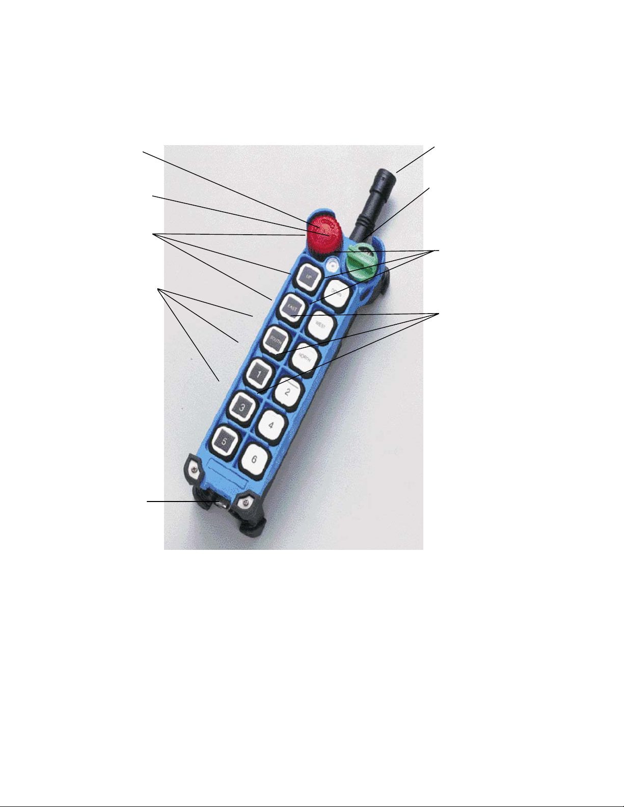
TRANSMITTER PARTS
Stop Button
LED indicator
Motion Buttons
Auxiliary Buttons
TCM260904 Rev 0.1
ANTENNA
Rotary Key
Switch
Motion Buttons
Auxiliary Buttons
Battery Cover
TCM260904 Page 7 of 31
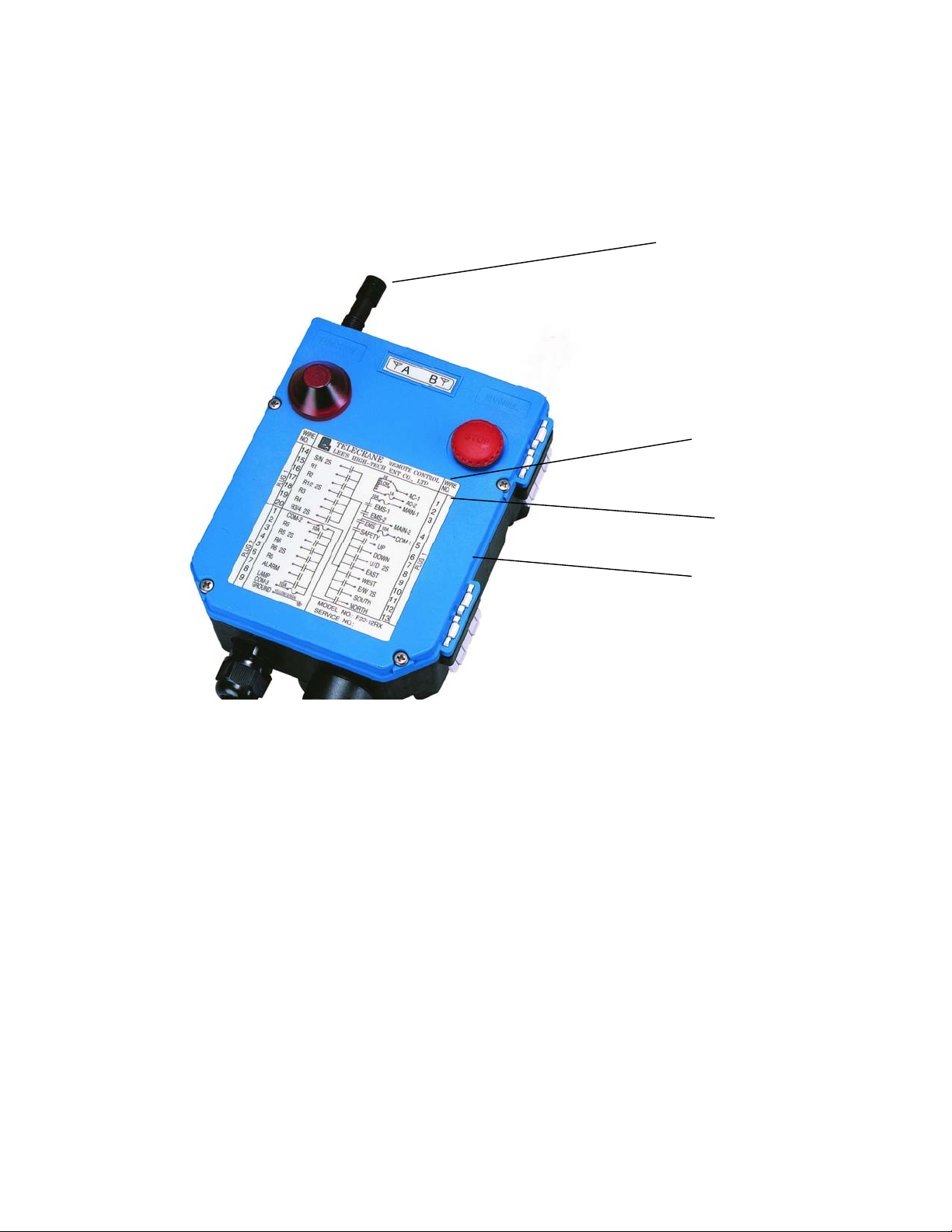
Receiver’s parts
(
(
)
TCM260904 Rev 0.1
Antenna
Receiver/
Decoder
Module
inside)
Relay
Module
inside
Transformer
(inside)
TCM260904 Page 8 of 31
INSTALLATION
(
t
)
)
PRECAUTIONS DURING INSTALLATION
(1) Observe all safety precau t io ns when climbing the crane.
(2) Turn off the main power source of crane before installation to avoid electric shock.
(3) Receiver must be installed in such a way that it will not touch any part of the building during the operation.
(4) Receiver must be fastened securely.
(5) Two external antennas must be used when receiver is installed in a me tal box.
(6) Before installation, inspect the crane’s safety devices, and make sure everything is in proper working
condition.
(7) Make sure you understand the crane circuits and power distribution as well as the function setting of remote
controller, to avoid incorrect wiring.
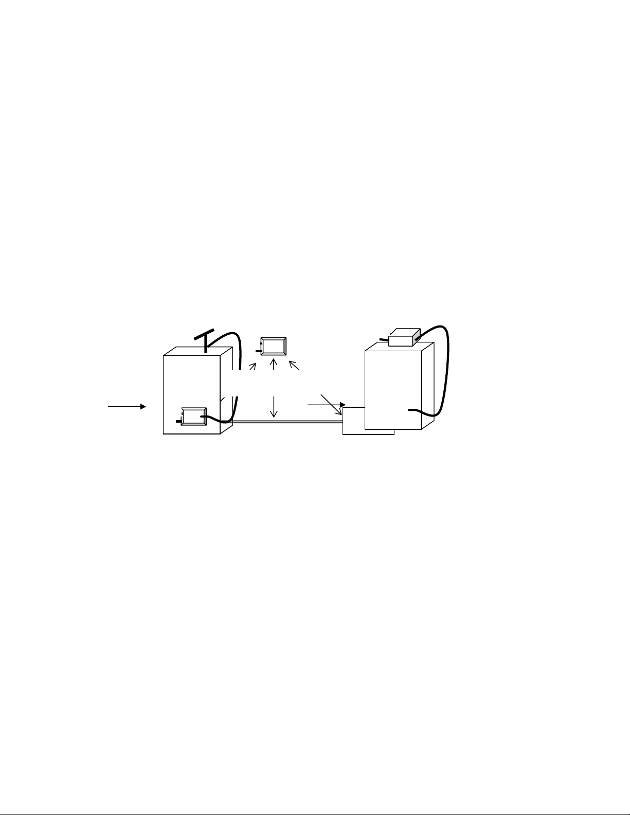
(8) To avoid any interference, the Receiver must be away from motors, frequency converter and power cable
(show as below).
(9) The Receiver should be installed on the top of the electrical control box. Don’t mount the receiver inside .
TCM260904 Rev 0.1
⌧
(Incorrect)
Motor
Antenna
Receiver
M
(Electrical
control box
Receiver
Cable
As far as possible
Cable
☺
Correc
Receiver
Cable
Frequency
Converter
(Electrical
control box)
TCM260904 Page 9 of 31
TCM260904 Rev 0.1
RECEIVER INSTALLATION INSTRUCTIONS
PREPARATION FOR INSTALLATION
(1) Provide all necessary tools.
(2) Select a proper location.
(3) Select a stable place.
(4) Select a place where you can see the Receiver or Antenna.
(5) Select a place where there ar e no sparks, e.g. keep away fr om motors, relays, magnetic switches and po wer
cables.
(6) Keep away from high-voltage wiring and devices.
(7) The Receiver case must be at least 3 cm away from other obstacles.
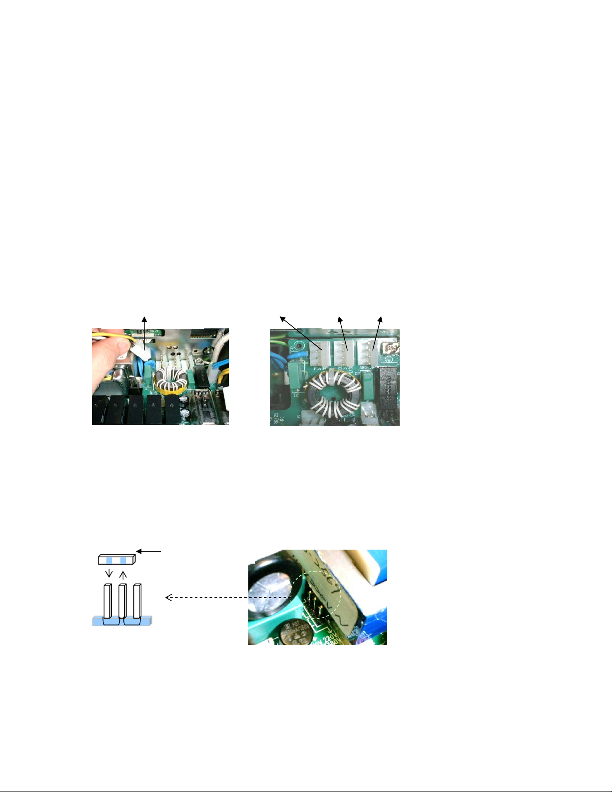
INSTALLATION OF PROPER POWER SOURCE
The input power source for the receiver can be 110/220/380 VAC (50/60 Hz) etc. After the power source is confirmed, one must
select the proper connector for the voltage applied to the relay module transformer primary winding.
Selective power supply for F21-12S/12D as illustration as below:
Power source plug
There are 3 kinds of voltage (110V/220V/ 380V) supplied in F21-12S/12D
This could be set as required before shipment, or follow the procedures to change the voltage you need.
(1) Turn off the Receiver.
(2) Pull out the power source plug from the previous voltage position
(3) Plug in the power source plug to the voltage you need.
(4) Complete.
Note: If the voltage you need is 48V/62V/110V, please contact distributor.
Selective power supply for F21-6D as illustration as below:
Black connector
110V 220V
There are 2 kinds of voltage (110V/220V) supplied in F21-6D
This could be set as required before shipment, or follow the procedures to change the voltage you need.
(1) Turn off the Receiver.
(2) Using tool to pull out the black connector from the previous voltage position.
(3) Using tool to plug in the black connector to the voltage you need.
(4) Complete.
110V 220V 380V
TCM260904 Page 10 of 31
 Loading...