

Page 1

VS1 Telephone System
Installation, Configuration
& Operating Guide
Intended for use in VS1 Systems
running TVS Software 2.10
June 2003
Man Rev 3
Telecor Inc.
1114 Westport Cr.
Mississauga, Ontario
Canada, L5T 1G1
Tel: (905) 564-0801
Fax: (905) 564-0806
Page 2

Copyright Notice
This manual and the software described in it are copyrighted, with all rights reserved. Under the
copyright laws, neither this manual nor the software may be copied, in whole or in part, without the
written consent of Telecor Inc. except as provided in the applicable Telecor Inc. software license
agreement. Under the law, copying includes translating into another language or format.
The software contains proprietary, confidential and unpublished information of Telecor Inc. No use
or disclosure of any portion of this manual may be made without the prior express written consent of
Telecor Inc.
© 2001-03 Telecor Inc. All Rights Reserved.
Printed in the United States of America.
Special Note for Government Users
This manual and the software described in it are provided with “Restricted Rights”. Please refer to
the applicable Telecor Inc. license agreement for a complete description of the rights granted.
Manufacturer:
Telecor Inc.
1114 Westport Crescent
Mississauga, ON L5T 1G1
Hardware Warranty
Please refer to the Telecor Inc. Registration Pak shipped with the
product.
Software Provided Under License
All software is provided pursuant to a license. Please refer to the Registration Pak for a complete
description of the rights granted.
Disclaimer
The Software and related documentation are provided “AS IS” and without warranty of any kind and
Telecor Inc. EXPRESSLY DISCLAIMS ALL WARRANTIES, EXPRESS OR IMPLIED,
INCLUDING, BUT NOT LIMITED TO, THE IMPLIED WARRANTIES OF
MERCHANTABILITY, FITNESS FOR A PARTICULAR PURPOSE AND NONINFRINGEMENT. TELECOR INC. DOES NOT WARRANT THAT THE FUNCTIONS
CONTAINED IN THE SOFTWARE WILL MEET YOUR REQUIREMENTS, OR THAT THE
OPERATION OF THE SOFTWARE WILL BE UNINTERRUPTED OR ERROR-FREE, OR THAT
DEFECTS IN THE SOFTWARE WILL BE CORRECTED. FURTHERMORE, TELECOR INC.
DOES NOT WARRANT OR MAKE ANY REPRESENTATIONS REGARDING THE US E OR
THE RESULTS OF THE USE OF THE SOFTWARE OR RELATED DOCUMENTATION IN
TERMS OF THEIR CORRECTNESS, ACCURACY, RELIABILITY, OR OTHERWISE. NO
ORAL OR WRITTEN INFORMATION OR ADVICE GIVEN BY TELECOR INC. OR A
TELECOR INC. AUTHORIZED REPRESENTATIVE SHALL CREATE A WARRANTY OR IN
ANY WAY INCREASE THE SCOPE OF THIS WARRANTY. SHOULD THE SOFTWARE
PROVE DEFECTIVE, YOU (AND NOT TELECOR INC. OR A TELECOR INC. AUTHORIZED
REPRESENTATIVE) ASSUME THE ENTIRE COST OF ALL NECESSARY SERVICING,
REPAIR, OR CORRECTION. UNDER NO CIRCUMSTANCES, INCLUDING NEGLIGENCE,
SHALL TELECOR INC. BE LIABLE FOR ANY INCIDENTAL, SPECIAL, OR
CONSEQUENTIAL DAMAGES THAT RESULT FROM THE USE OF OR INABILITY TO USE
THE SOFTWARE OR RELATED DOCUMENTATION, EVEN IF TELECOR INC. OR A
TELECOR INC. AUTHORIZED REPRESENTATIVE HAS BEEN ADVISED OF THE
POSSIBILITY OF SUCH DAMAGES.
The Software is not designed or licensed for use in in-line control of equipment in hazardous
environments such as operation of nuclear facilities, aircraft navigation or control, or direct life
support machines.
Telecor Inc. reserves the right to revise this publication and to make changes to its content, at any
time, without any obligation to notify any person or entity of such revisions or changes.
Trademarks
Telecor, the Telecor logo, VS1, CTIM, PCOM, Attendant, Call, and Connect are trademarks or
registered trademarks of Telecor Inc. Microsoft, MS-DOS, Windows, and Windows NT are
trademarks or registered trademarks of Microsoft Corporation. Predator 747 is a trademark of
American Predator Corporation. AT&T is a trademark of AT&T. Boca is a trademark of Boca
Research, Inc. Caldera and DR-DOS are registered trademarks of Caldera, Inc. G486VPC is a
trademark of Diamond Flower, Inc. GVC is a registered trademark of Global Village Communication,
Inc. Intel is a registered trademark of Intel Corporation. MaxTech is a registered trademark of
MaxTech Corporation. Megahertz, Sportster, and U.S. Robotics are registered trademarks of 3Com
Corporation. Novell is a registered trademark of Novell, Inc. Plantronics, SP, Supra, and TriStar are
trademarks or registered trademarks of Plantronics, Inc. Sound Blaster is a registered trademark of
Creative Technology, Ltd. TDK is a registered trademark of TDK Systems, Inc. Zoom is a registered
trademark and Zoom/FaxModem and ZoomCam are trademarks of Zoom Telephonics, Incorporated.
Patents
Patents Pending
Environmental Specifications
See the Hardware section for specific product specifications.
FCC Information
This equipment complies with Part 68 of the FCC rules. On the bottom of this equipment, there is
a label that contains, among other information, the FCC Registration Number and Ringer
Equivalence Number (REN) for this equipment. The telephone company may require this
information prior to connection of this equipment.
This equipment requires USOC connectors listed below which are provided in the installation of
the Telecor VS1 business telephone system.
An FCC compliant telephone cord and modular plug is provided with this equipment. This
equipment is designed to be connected to the telephone network or premises wiring using a
compatible modular jack which is Part 68 compliant.
The REN is useful to determine how many devices you may connect to a single telephone line and
still have all of those devices ring when your number is called. In most, but not all areas, the sum
of all RENs per line should be five (5.0) or less. Your local telephone company can verify the
maximum REN per line for your calling area.
If this equipment causes harm to the telephone network, the telephone company may notify you in
advance that temporary discontinuance of service is required. If advance notice is not practical,
the telephone company will notify you of discontinuance as soon as possible. You will also be
advised of your right to file a complaint with the FCC.
The telephone company may make changes in its facilities, equipment, operations or procedures
that could affect the operation of your telephone equipment. If this happens, the telephone
company will provide advance notice so that you can modify your equipment to maintain
uninterrupted service.
If the trouble causes harm to the network, the telephone company may ask you to disconnect this
equipment from the network until the problem has been solved. If you experience trouble with
this telephone equipment, please contact:
Telecor Inc., 1114 Westport Crescent, Mississauga, ON L5T 1G1 Technical Support: (800) 4643274, Mississauga. www.Telecor.com
You should not try to repair this equipment yourself. Changes or modifications not expressly
approved by Telecor Inc. could void your authority to operate the equipment.
This equipment may not be used on public coin service provided by the telephone company.
Connection to party lines is subject to state tariffs. (Contact your state public utility commission
or corporation commission for information.)
This equipment is hearing aid compatible.
Note: This equipment has been tested and found to comply with the limits for a Class A digital
device, pursuant to part 15 of the FCC Rules. These limits are designed to provide reasonable
protection against harmful interference when the equipment is operated in a commercial
environment. This equipment generates, uses and can radiate radio frequency energy and if not
installed and used in accordance with the instruction manual, may cause harmful interference to
radio communications. Operation of this equipment in a residential area is likely to cause harmful
interference in which case the user will be required to correct the interference at their own
expense.
This equipment is capable of providing users access to interstate providers of operator services
through the use of access codes. Modification of this equipment by call aggregators to block
access dialing codes is a violation of the Telephone Operator Consumers Act of 1990.
Trade Name(s): TelecorTM VS1TM Business Telephone System
FCC Registration Number: 5NBUSA-32975-MY-E
IC Certification Number: 2403 6616 A
AC REN: (Base System) 1.3B and (T1) N/A
Connectors: (FCC USOC) RJ11C/21X/48 and (IC) CA11A/CA21A/CA81A
Authorized Network Ports: (FCC FIC) 02LS2 04DU9-BN/DN/1KN/1SN/1ZN and (IC)
LS/DI1/DI2/DI3
Trade Name: Telecor Cut-Over Box
FCC Registration Number: 5NBUSA-32976-PX-N
AC REN: 1.0B with CID; 0.0B without CID
Connectors: (USOC) RJ-11
Authorized Network Ports: (FIC) 02LS2
Trade Name: Display Phone
FCC Registration Number: FTZCHN-31227-KX-E
IC Certification Number: 2760 7997 A
AC REN: 1.6B
Connectors: (FCC USOC) RJ11C and (IC) CA11A
Authorized Network Port: (FCC FIC) 02LS2 and (IC) LS
Additional Information
This document is current as of the date of publication. Refer to the Telecor Web site,
www.telecor.com, for supplemental information.
For TVS Software 2.10
Man Rev: 3
June 2003
E:\VS1 Documents\VS1 ICO\Telecor Manual
iii
Page 3

CS-03 Information (Canada)
NOTICE: The Industry Canada label identifies certified equipment. The certification means that the
equipment meets certain telecommunications network protective, operational and safety requirements.
The Department does not guarantee the equipment will operate to the user's satisfaction.
Before installing this equipment, users should ensure that it is permissible to be connected to the
facilities of the local telecommunications company. The equipment must also be installed using an
acceptable method of connection. The customer should be aware that compliance with the above
conditions may not prevent the degradation of service in some situations.
Repairs to certified equipment should be made by an authorized Canadian maintenance facility
designated by the supplier. Any repairs or alterations made by the user to this equipment, or
equipment malfunctions, may give the telecommunications company cause to request the user to
disconnect the equipment.
Users should ensure for their own protection that the electrical ground connections of the power
utility, telephone lines and internal metallic water pipe system, if present, are connected together. This
precaution may be particularly important in rural areas.
CAUTION: Users should not attempt to make such connections themselves, but should contact the
appropriate electric inspection authority or electrician as appropriate.
NOTICE: The Ringer Equivalence Number (REN) assigned to each terminal device provides an
indication of the maximum number of terminals allowed to be connected to a telephone interface. The
termination on an interface may consist of any combination of devices subject only to the requirement
that the sum of the Ringer Equivalence Numbers of all the devices does not exceed 5.
CS-03 Information (Canada)
AVIS: L'étiquette d'Industrie Canada identifie le matériel homologué. Cette étiquette certifie que
le matériel est conforme aux normes de protection, d'exploitation et de sécurité des réseaux de
télécommunications, comme le prescrivent les documents concernant les exigences techniques
relatives au matériel terminal. Le Ministère n'assure toutefois pas que le matériel fonctionnera à la
satisfaction de l'utilisateur.
Avant d'installer ce matériel, l'utilisateur doit s'assurer qu'il est permis de le raccorder aux
installations de l'entreprise local de télécommunication. Le matériel doit également être installé en
suivant une méthode acceptée de raccordement. L'abonné ne doit pas oublier qu’il est possible que
la conformité aux conditions énoncées ci-dessus n'empêche pas la dégradation du service dans
certaines situations.
Les réparations de matériel homologué doivent être coordonnées par un représentant désigné par
le fournisseur. L'enterprise de télécommunications peut demander à l'utilisateur de débrancher un
appareil à la suite de réparations ou de modifications effectuées par l'utilisateur ou à cause de
mauvais fonctionnement.
Pour sa propre protection, l'utilisateur doit s'assurer que tous les fils de mise à la terre de la source
d'énergie électrique, de lignes téléphoniques et des canalisations d'eau métalliques, s'il y en a, sont
raccordés ensemble. Cette précaution est particulièrement importante dans les régions rurales.
AVERTISSEMENT: L'utilisateur ne doit pas tenter de faire ces raccordements lui-même; il doit
avoir recours à un service d'inspection des installations électriques, ou à un électricien, selon le
cas.
AVIS: L'indice d'équivalance de la sonnerie (IES) assigné à chaque dispositif terminal indique le
nombre maximal de terminaux qui peuvent être raccordés à une interface. La terminaison d'une
interface téléphonique peut consister en une combinaison de quelques dispositifs, à la seule
condition que la somme d'indices d'équivalence de la sonnerie de tous les dispositifs n'excède pas
5.
iv
Page 4

Important Safety Instructions
When using your telephone equipment, basic safety precautions should always be followed to reduce the risk of fire, electric
shock, and injury to persons, including the following.
1. Read and understand all instructions.
2. Follow all warnings and instructions marked on the product.
3. Unplug this product from the wall outlet before cleaning.
4. Do not use this product near water (for example, in a wet basement).
5. Do not place this product on an unstable cart, stand or table.
6. Slots and openings in the cabinet and the back and bottom are provided for ventilation, to protect it from overheating;
these openings must not be blocked or covered. This product should never be placed near a radiator or heat register.
This product should not be placed in a built-in installation unless proper ventilation is provided.
7. This product should be operated only from the type of power source indicated in the manual. If you are not sure of the
power source to your building, consult your dealer or local power company.
8. Some pieces of equipment have a three-wire grounding type plug, a plug having a third grounding pin. This plug will
only fit safely into a grounded power outlet. This is a safety feature. If you are unable to insert the plug into a grounded
outlet, contact your electrician. Do not defeat the safety purpose of the grounded plug.
Some pieces of equipment have a polarized line plug, where one blade of the plug is wider than the other. This plug will
fit into the power outlet only one way. This is a safety feature. If you are unable to insert the plug fully into the outlet,
try reversing the plug. If the plug still does not fit, contact your electrician. Do not defeat the safety purpose of the
polarized plug.
9. Do not allow anything to rest on the power cord. Do not locate this product where the cord will be abused by persons
walking on it.
10. Do not use an extension cord with this product’s AC power cord. Equipment not associated with the telephone system
should not be plugged into the same AC outlet.
11. Never push objects of any kind into this product through the cabinet slots as they may touch dangerous voltage points,
or short out parts that could result in risk of fire or electric shock. Never spill liquid of any kind on the product.
12. To reduce the risk of electrical shock, do not disassemble this product. Take it to a qualified service vendor, when
service or repair work is required. Opening or removing covers may expose you to dangerous voltages or other risks.
Incorrect reassembly can cause electric shock when the product is subsequently used.
13. Unplug this product from the wall outlet and refer servicing to a qualified service vendor under the following
conditions:
A. When the power supply cord or plug is damaged or frayed.
B. If liquid has been spilled into the product.
C. If the product has been exposed to rain or water.
D. If the product does not operate normally by following the operating instructions. Adjust only those controls that
are covered by the operating instructions. Improper adjustment of other controls may result in damage and will
often require extensive work by a qualified technician to restore the product to normal operation.
E. If the product has been dropped or the cabinet has been damaged.
F. If the product exhibits a distinct change in performance.
14. Avoid using a telephone (other than cordless type) during an electrical storm. There may be a remote risk of electric
shock from lightning.
15. Do not use the telephone to report a gas leak in the vicinity of a leak.
v
Page 5

TABLE OF CONTENTS
INTRODUCTION........................................................................................................................XV
Using this Guide ..................................................................................................................... xvi
Conventions in this Guide ......................................................................................................xvi
Font Styles Used ................................................................................................................... xvii
HARDWARE ............................................................................................................ 1
HARDWARE OVERVIEW ............................................................................................................3
Telecor Voice Server (TVS) Model 200 ....................................................................................4
Hardware Specifications ........................................................................................................4
I/O Port and IRQ Usage.........................................................................................................5
Port Expansion Unit (PEU)........................................................................................................7
PEU 250.................................................................................................................................7
PEU 205.................................................................................................................................7
PEU 200.................................................................................................................................7
Hardware Specifications ........................................................................................................8
Dry Contact Unit (PV-DCU-100) ...............................................................................................9
Hardware Specifications ........................................................................................................9
Cut-Over Box...........................................................................................................................10
Hardware Specifications ......................................................................................................10
Host Adapter Cards.................................................................................................................11
Hardware Specifications ......................................................................................................11
Caller ID Option Module..........................................................................................................12
Hardware Specifications ......................................................................................................12
10Base-T Network Interface Card...........................................................................................13
Hardware Specifications ......................................................................................................13
T1 Interface Card ....................................................................................................................14
Hardware Specifications ......................................................................................................14
TVS VGA Video Card..............................................................................................................15
Hardware Specifications ......................................................................................................15
SC200 Switch Card .................................................................................................................16
Hardware Specifications ......................................................................................................16
Computer Telephony Interface Module (CTIM).......................................................................17
Hardware Specifications ......................................................................................................17
PC Option Module (PCOM).....................................................................................................18
Hardware Specifications ......................................................................................................18
ACD Status Board ...................................................................................................................19
ACD Status Board Manufacturer .........................................................................................19
HARDWARE CONFIGURATION & INSTALLATION ................................................................20
Configuring the PEU 250.........................................................................................................20
Cut-Over Functioning on the PEU 250 ................................................................................20
Configuring the PEU 205 and 200 ..........................................................................................21
Rack Mount Setup...................................................................................................................23
Wall Mount Setup ....................................................................................................................24
PEU Wiring Requirements ......................................................................................................25
Terminal Blocks ...................................................................................................................25
Connecting the Telecor Voice Server (TVS) ...........................................................................26
TVS to PEU 250 ..................................................................................................................26
TVS to PEU 205 ..................................................................................................................27
Installing Additional PEUs .......................................................................................................28
External Contacts – PEU 205 .................................................................................................29
VS1 Installation, Configuration & Operating Guide vii
Page 6

Connecting Zone Pager Outputs on a PEU 205..................................................................29
Connecting Music Inputs on a PEU 205..............................................................................29
Connecting Relay Outputs on a PEU 205 ...........................................................................30
Installing the Dry Contact Unit Model 100...............................................................................30
External Contacts – Dry Contact Unit Model 100 ...................................................................31
Connecting Zone Pager Outputs on a DCU ........................................................................31
Connecting Music Inputs on a DCU ....................................................................................31
Connecting Relay Outputs on a DCU..................................................................................31
Installation Checklist ............................................................................................................32
Connecting the Cut-Over Box .................................................................................................33
Testing the Cut-Over Box ....................................................................................................34
Cut-Over Box Checklist .......................................................................................................34
Installing a Host Adapter Card ................................................................................................35
Host Adapter Cards Checklist..............................................................................................37
Installing the Caller ID Option Module.....................................................................................38
Verifying the Caller ID Option Module .................................................................................39
Caller ID Option Module Checklist.......................................................................................39
Installing a 10Base-T Network Interface Card ........................................................................40
Configuring the 10Base-T Network Interface Card .............................................................40
10Base-T Network Interface Card Checklist .......................................................................41
Installing a T1 Interface Card ..................................................................................................42
Ordering T1 Service.............................................................................................................42
Installing the T1 Interface Card ...........................................................................................43
Cable Installation .................................................................................................................44
Installing the CTIM ..................................................................................................................45
CTIM Checklist ....................................................................................................................45
Installing the PC Option Module (PCOM) ...............................................................................46
PCOM Checklist ..................................................................................................................46
CREATING AN EMERGENCY BOOT FLOPPY........................................................................47
TEL-SITE ..............................................................................................................49
OVERVIEW OF TEL-SITE..........................................................................................................51
Tel-Site Windows ....................................................................................................................52
The Connection Window......................................................................................................52
The Configuration Window ..................................................................................................53
The Explorer Window ..........................................................................................................54
The Terminal Window..........................................................................................................55
Setting up a New Site..............................................................................................................56
How Tel-Site Organizes Site Information ................................................................................57
Opening a Site.........................................................................................................................57
CONNECTION METHODS.........................................................................................................58
Tel-Site Modem to TVS Modem through two PEU ports (on-site) ..........................................58
TVS Configuration ...............................................................................................................58
Hardware Setup...................................................................................................................60
Tel-Site Setup ......................................................................................................................61
Tel-Site Modem to TVS Modem through
Two PEU Extension Ports Connection Checklist ................................................................62
TVS Modem as an Extension Connection (off-site access)....................................................63
TVS Configuration ...............................................................................................................63
Hardware Setup...................................................................................................................64
Tel-Site Setup ......................................................................................................................65
TVS Modem as an Extension Connection Checklist ...........................................................66
Dedicated CO Line to TVS Modem Connection (off-site access)...........................................67
viii Table of Contents
Page 7

TVS Configuration ...............................................................................................................67
Hardware Setup...................................................................................................................68
Tel-Site Setup ......................................................................................................................68
Dedicated CO Line to TVS Modem Connection Checklist ..................................................69
TVS Modem Shares a CO Line Connection (off-site access).................................................70
About Direct Inward System Access (DISA)........................................................................70
TVS Configuration ...............................................................................................................70
Configure the TVS modem to not answer the Tel-Site modem call ....................................70
Enabling DISA on the CO Port connected to the TVS modem ...........................................71
Setting up a DISA Password on an Extension Port.............................................................72
Uploading new settings and reloading changes..................................................................73
Hardware Setup...................................................................................................................73
Tel-Site Setup ......................................................................................................................73
TVS Modem Shares a CO Line Connection Checklist ........................................................75
TEL-SITE BASIC OPERATION .................................................................................................76
Connecting to a Site ................................................................................................................76
Downloading Files from a Site.................................................................................................77
Changing Site Configurations .................................................................................................77
Remote System Access (RSA) Password...........................................................................78
Uploading Files to a Site .........................................................................................................78
Reloading Configuration Changes ..........................................................................................79
System Reset Required.......................................................................................................80
VS1 EDITOR ......................................................................................................... 81
OVERVIEW OF VS1 EDITOR ....................................................................................................83
ACTIVATION KEYS ...................................................................................................................84
Receiving Activation Keys .......................................................................................................84
Installing Activation Keys.........................................................................................................85
ADAPTER SETUP......................................................................................................................86
AUTOMATIC CALL DISTRIBUTION .........................................................................................87
Creating an ACD .....................................................................................................................88
ACD Account Codes............................................................................................................88
Configuring an ACD ................................................................................................................90
Over _____calls per _____agents.......................................................................................91
Queued call age is _____seconds ......................................................................................91
Zero agents are logged in....................................................................................................92
AUTO ATTENDANTS (AA)........................................................................................................93
The Four Basic Functions of Auto Attendants.........................................................................93
Preconfigured Auto Attendants ...............................................................................................94
Reviewing the Default Auto Attendant.................................................................................95
Creating an Auto Attendant.....................................................................................................96
Caller Greeting ........................................................................................................................97
Caller Greeting – Play Message..........................................................................................97
Caller Greeting – Say Phrase..............................................................................................99
Caller Greeting – Say Current Date & Time ..................................................................... 100
Caller Greeting – Run System Command File ................................................................. 100
Get Caller Response ............................................................................................................ 101
Caller Response Handler ..................................................................................................... 102
Caller Response ............................................................................................................... 102
Caller Response – Touch Tone........................................................................................ 103
Caller Response – Multi-digit Number.............................................................................. 103
VS1 Installation, Configuration & Operating Guide ix
Page 8

Caller Response – Number Range................................................................................... 104
Caller Response – Caller Response Timeout .................................................................. 104
Sending the Caller to Another Procedure......................................................................... 104
Assigning a System Action ............................................................................................... 105
System Action – Transfer to an Extension ....................................................................... 105
System Action – Transfer to an Outside Line................................................................... 106
System Action – Dial a Number........................................................................................ 107
System Action – Play Message ........................................................................................ 107
System Action – Record Message ................................................................................... 109
System Action – Say Phrase ............................................................................................ 110
System Action – Say Current Date and Time................................................................... 111
System Action - Run System Command Script ................................................................ 111
Default System Action .......................................................................................................... 112
Importing an Auto Attendant Procedure............................................................................... 112
Viewing the Auto Attendant Script........................................................................................ 113
CALLER ID ROUTING ............................................................................................................ 114
Routing Calls from a Specific Area Code............................................................................. 115
COMMAND SCRIPTS ............................................................................................................. 116
Default Command Scripts .................................................................................................... 117
Running a Command Script from the TVS Command Prompt ............................................ 118
Running a Command Script from a Phone .......................................................................... 118
Running a Command Script from an Auto Attendant........................................................... 118
System Commands .............................................................................................................. 120
CONFERENCE ROOMS ......................................................................................................... 125
DID & DNIS ROUTING ............................................................................................................ 126
Configuring a Port for T1 Service......................................................................................... 126
Assigning the Port as a CO Line ...................................................................................... 126
Configuring the Port for DID or DNIS ............................................................................... 127
Setting up a DID or DNIS Routing Table.............................................................................. 128
FORCED ACCOUNTS............................................................................................................. 130
FUNCTION KEYS.................................................................................................................... 131
GUEST MAIL BOXES ............................................................................................................. 133
LEAST COST ROUTING......................................................................................................... 134
How a Long Distance Call is Routed.................................................................................... 135
LINE POOLS ........................................................................................................................... 136
LOOP TAPES .......................................................................................................................... 138
Changing a Voice File Playing as a Loop Tape ................................................................... 139
PAGE ZONES.......................................................................................................................... 140
PORT CONFIGURATIONS ..................................................................................................... 142
Creating a New Configuration .............................................................................................. 142
Copying a Complete Configuration ...................................................................................... 143
Replicating Individual Port Settings...................................................................................... 144
Setting up a CO Port Type ................................................................................................... 147
Setting up an Extension Port Type....................................................................................... 149
PROGRAM PASSWORD ........................................................................................................ 153
Removing a Program Password .......................................................................................... 153
x Table of Contents
Page 9

SCHEDULED EVENTS ........................................................................................................... 154
SYSTEM SPEED DIAL............................................................................................................ 156
Dialing System Speed Dials from a Station Option.............................................................. 156
SYSTEM CONFIGURATION 1................................................................................................ 157
SYSTEM CONFIGURATION 2................................................................................................ 160
TOLL RESTRICTIONS............................................................................................................ 162
Denying Additional Numbers in the Default Scheme ........................................................... 162
Creating a New Toll Restriction Scheme ............................................................................. 163
Allowing Entries in a Toll Restriction Scheme...................................................................... 164
WORK GROUPS ..................................................................................................................... 165
VALIDATING THE CONFIGURATION ................................................................................... 167
Displaying Errors .................................................................................................................. 167
VS1 EDITOR – LIMITED FEATURE VERSION...................................................................... 168
STATION OPTIONS...............................................................................................169
STATION OPTIONS OVERVIEW............................................................................................ 171
Overview of Attendant .......................................................................................................... 172
Product Features .............................................................................................................. 173
Requirements ................................................................................................................... 173
Includes (Part Number: PVS-SCT-A01) ........................................................................... 173
Using Attendant—Basic Operation ...................................................................................... 174
Selecting a Call................................................................................................................. 174
Connecting to a Call ......................................................................................................... 174
Placing a Call On Hold...................................................................................................... 174
Taking a Call Off Hold....................................................................................................... 174
Disconnecting a Call ......................................................................................................... 174
Transferring a Call to an Extension Unannounced........................................................... 174
Transferring a Call to an Extension Announced............................................................... 175
Transferring a Call to an Extension’s Voice Mail .............................................................. 175
Making an Outside Call..................................................................................................... 175
Making an Inside Call ....................................................................................................... 175
Overview of Connect ............................................................................................................ 176
Product Features .............................................................................................................. 177
Requirements ................................................................................................................... 177
Includes (Part Number: PVS-SCT-T01) ........................................................................... 177
Using Connect—Basic Operation ........................................................................................ 178
Making a Call .................................................................................................................... 178
Disconnecting a Call ......................................................................................................... 178
Answering a Call............................................................................................................... 178
Redialing a Number .......................................................................................................... 178
Placing a Call On Hold...................................................................................................... 178
Transferring a Call - Announced....................................................................................... 179
Transferring a Call - Unannounced .................................................................................. 179
Transferring a Call to Voice Mail ...................................................................................... 179
Transferring a Call to Your Voice Mail.............................................................................. 179
Overview of Display Phone Model 200 (DP200).................................................................. 180
Product Features .............................................................................................................. 181
Using the DP200—Basic Operation..................................................................................... 181
Making an Internal Call ..................................................................................................... 181
VS1 Installation, Configuration & Operating Guide xi
Page 10

Making an External Call.................................................................................................... 181
Answering a Call............................................................................................................... 182
Answering Multiple Calls................................................................................................... 182
Transferring a Call ............................................................................................................ 182
Placing a Call on Hold ...................................................................................................... 182
Taking a Call off Hold ....................................................................................................... 182
Redialing the Last Number Called.................................................................................... 182
Changing the Number of Lines Available ......................................................................... 182
DP200 Programmable Function Codes ............................................................................... 183
Overview of the HS-1301-LN Telephone ............................................................................. 185
Product Features .............................................................................................................. 185
Using the HS-1301-LN—Basic Operation............................................................................ 186
Making an Internal Call ..................................................................................................... 186
Making an External Call.................................................................................................... 186
Answering a Call............................................................................................................... 186
Transferring a Call ............................................................................................................ 186
Placing a Call On Hold...................................................................................................... 186
Taking a Call Off Hold....................................................................................................... 186
Redialing the Last Number Called.................................................................................... 186
Quick Guide to VS1 Phone System Feature Keystrokes..................................................... 187
VOICE MAIL ON THE VS1 PHONE SYSTEM........................................................................ 188
Gaining Access to Your Voice Mail with Telecor Attendant or Connect .............................. 188
Gaining Access to Your Voice Mail with the DP200 ............................................................ 188
Gaining Access to Your Voice Mail with the HS-1301-LN ................................................... 188
The Main Voice Mail Prompts .............................................................................................. 188
Using the Keypad Dialer for Voice Mail Features............................................................. 189
Listening to a Voice Mail Message....................................................................................... 189
Setting Up Voice Mail Features............................................................................................ 190
Creating or Changing Your Voice Mail Passcode................................................................ 190
Recording a Voice Mail Greeting ......................................................................................... 191
Setting Up Your Name in the Dial By Name Directory......................................................... 191
Sending a Message to an Individual or a Work Group ........................................................ 191
Sending a Message to an Individual................................................................................. 191
Sending a Message to a Range of Extensions................................................................. 192
Sending a Message to a Work Group .............................................................................. 192
Forwarding a Voice Mail Message to an Individual or a Work Group.................................. 192
Forwarding a Voice Mail Message to an Individual .......................................................... 192
Forwarding a Voice Mail Message to a Range of Extensions .......................................... 193
Forwarding a Voice Mail Message to a Work Group........................................................ 193
Gaining Access to Your Voice Mail From Another Internal Telecor VS1 Station................. 193
Gaining Access to Your Voice Mail From an External Line ................................................. 194
Voice Mail Notification on a Digital Pager ............................................................................ 194
Basic Voice Mail Notification............................................................................................. 194
Gaining Access to Basic Voice Mail Notification Settings ................................................ 194
Turning On Basic Voice Mail Notification on a Digital Pager............................................ 195
Turning Off Basic Voice Mail Notification on a Digital Pager............................................ 195
Advanced Voice Mail Notification ..................................................................................... 195
Gaining Access to the Advanced Voice Mail Notification Options.................................... 195
Setting Up Voice Mail Notification to up to Three Digital Pagers ..................................... 195
Canceling Voice Mail Notification to Multiple Pagers ....................................................... 196
Setting the Number of Paging Attempts ........................................................................... 196
Setting the Paging Interval................................................................................................ 196
Redirecting New Voice Mail Messages to Other Extensions ........................................... 196
Turning Off Redirecting New Voice Mail Message ........................................................... 197
xii Table of Contents
Page 11

REFERENCE........................................................................................................199
OVERVIEW OF REFERENCE ................................................................................................ 201
DEFAULT EXTENSIONS & ACCESS CODES ...................................................................... 202
Default Extensions ............................................................................................................... 202
Access Codes ...................................................................................................................... 202
DIRECT INWARD SYSTEM ACCESS (DISA)........................................................................ 203
DISA Example ...................................................................................................................... 203
Enabling DISA on a CO Port ................................................................................................ 203
Setting up a DISA Password on an Extension Port ............................................................. 205
DSP VOLUME ADJUSTMENTS ............................................................................................. 206
Sample DSP Volume Adjustments....................................................................................... 206
Adjusting DSP Volume through the Startup Command Script............................................. 207
Adjusting DSP Volume on CO Line Connected to an Auto Attendant or Voice Mail ........... 207
SETTING THE SYSTEM DATE AND TIME ............................................................................ 209
TELECOR VOICE SERVER FLOW CHARTS ........................................................................ 210
Inbound CO Call................................................................................................................... 210
Outbound CO Call ................................................................................................................ 211
Auto Attendant—Single Procedure ...................................................................................... 213
Auto Attendant—Multiple Procedure.................................................................................... 214
Automatic Call Distributor..................................................................................................... 215
LINE STATUS SYMBOLS....................................................................................................... 216
TELECOR VOICE SERVER SYSTEM COMMANDS ............................................................. 218
RECORDING VOICE FILES.................................................................................................... 220
Recording Using the Voice Message Recorder ................................................................... 220
Recording Using the PEU-205 or DCU ................................................................................ 220
Playing a Voice File Using the Command Prompt ............................................................... 221
PRE-RECORDED MESSAGE LIST........................................................................................ 222
Phrase List............................................................................................................................ 223
SCHEDULED DISK OPTIMIZATION ...................................................................................... 224
STATION MESSAGE DETAIL RECORDING (SMDR) ........................................................... 225
Designating SMDR Output Files .......................................................................................... 226
Backing up SMDR Output Files ........................................................................................... 226
Command Script Sample to Copy SMDR Files on Tuesday ............................................ 227
Gaining Access to SMDR Backup Files ............................................................................... 228
Copying SMDR Backup Files to a Disk at the TVS .......................................................... 228
Copying SMDR Files through a Network.......................................................................... 228
Copying SMDR Files through Tel-Site.............................................................................. 229
Interpreting Summary SMDR Data ...................................................................................... 230
Codes for Call Reason (Field 3) of Summary SMDR........................................................... 231
Additional Port Numbers Used in Extension Port (Field 5)............................................... 231
Interpreting Detail SMDR Data............................................................................................. 232
Codes for Call Reason (Field 3) of Detail SMDR................................................................. 233
Additional Port Numbers Used in Extension Port (Field 5)............................................... 233
Interpreting ACD SMDR Data .............................................................................................. 234
Action Codes for Field 10 of ACD SMDR Data .................................................................... 235
Interpreting ACD Queue Status SMDR Data.................................................................... 235
VS1 Installation, Configuration & Operating Guide xiii
Page 12

Interpreting Day SMDR Data................................................................................................ 236
Codes for Port Type (Field 3) of Day SMDR Data............................................................ 236
VS CALL ACCOUNTING ........................................................................................................ 237
Requirements ................................................................................................................... 237
VERIFYING CO DISCONNECT SIGNALS ............................................................................. 240
T1 INTERFACE CARD CONFIGURATION ............................................................................ 242
T1 Interface Card Parameter Setup Using Tel-Site ............................................................. 242
T1 Interface Card Setup Using VS1 Editor .......................................................................... 247
Adapter Setup................................................................................................................... 247
Configuring a T1 Port as a CO Line ................................................................................. 248
Configuring a T1 Port for DID or DNIS ............................................................................. 248
Setting Up a DID or DNIS Routing Table ......................................................................... 249
T1 Interface Card Diagnostics.............................................................................................. 251
T1 Status Screen .............................................................................................................. 252
T1 Interface Card Checklist .............................................................................................. 255
GLOSSARY OF TERMS ......................................................................................................... 256
INDEX .................................................................................................................266
xiv Table of Contents
Page 13
INTRODUCTION
The Telecor VS1 phone system is a PC-based expandable PBX. The base system has two main
components: the Telecor Voice Server (TVS) and the Telecor Port Expansion Unit (PEUs). Each
PEU provides 16 ports. Up to 11 additional PEUs can be added with 16 ports each, enabling the
Telecor VS1 phone system to expand to 192 ports, depending upon the type of station sets used.
A number of station options are available in the form of Computer Telephony Integration (CTI)
applications or desk phones. The system is managed with the Tel-Site system management
application, and configured with the VS1 Editor configuration application.
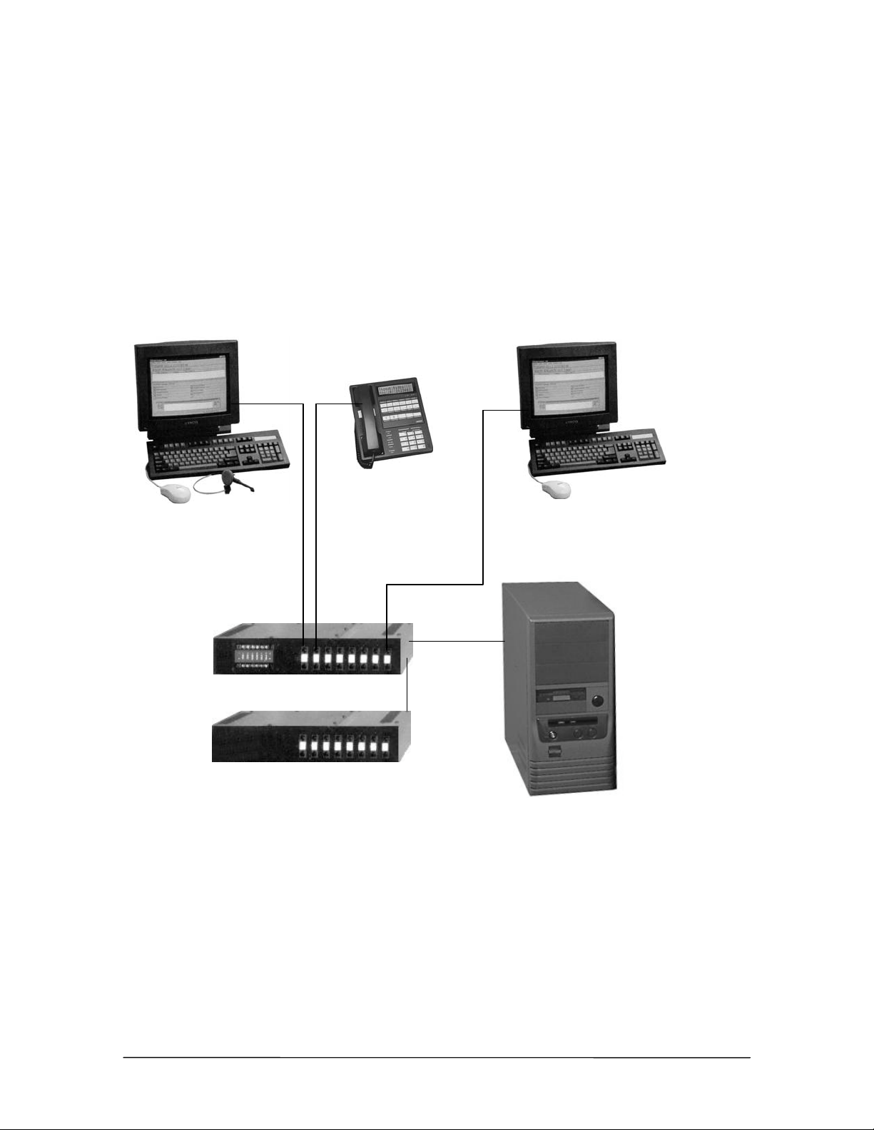
The diagram below shows the main components of the Telecor VS1 phone system.
Phones
CTI Client Applications
• Attendant
• Connect
• DP200 Display Phone
• Telecor HS-1301-LN
Phone
System Management & Configuration
• Tel-Site System Management application
• VS1 Editor Configuration application
Telecor Port Expansion Unit Model 205
Telecor Port Expansion Unit Model 200
The components of a
Telecor VS1 phone
system
Telecor Voice Server Model 200
VS1 Installation, Configuration & Operating Guide xv
Page 14

Using this Guide
This guide is designed to instruct Telecor Value Added Resellers how to install and configure the
VS1 phone system. Follow the instructions and recommendations provided to ensure proper
installation and operation of the Telecor VS1 phone system. This guide is organized into six
sections to address specific areas of the Telecor VS1 phone system.
Section 1 introduces the VS1 hardware and provides installation and configuration instructions for
the hardware.
Section 2 provides an overview of the Tel-Site system management application, and details the
different connection methods available (on-site and off-site) for connecting to a customer site.
Section 3 gives instructions on using the VS1 Editor configuration application to configure a VS1
phone system.
Section 4 introduces the different station options available, along with quick operating instructions
and voice mail features.
Section 5 provides extensive Reference information, such as Station Message Detail Recording
(SMDR) information. Also includes a glossary of terms.
Section 6 provides a comprehensive Index.
Conventions in this Guide
This guide is designed to help you install and configure the Telecor VS1 phone system quickly and
efficiently. There are some words and symbol conventions used throughout the guide to help you
along the way.
• If you are not at the system site (off-site) or are on a remote computer, and are using the Tel-
Site system management and VS1 Editor configuration application, you are asked to Click
certain buttons with the mouse.
• If you are configuring the system at the system site (on-site) using a monitor and keyboard,
and the guide directs you to select a command or selection, you need to press the
UP/DOWN/RIGHT/LEFT arrows, or press TAB, on the keyboard to move to that selection or
command, and then press
• If you are asked to Type, it means you are to use the keyboard on your computer.
• You are asked to Press certain buttons on the phone, or keyboard, to perform a series of steps.
• When you see a graphic in the left margin, it means you are to click the corresponding button
on the window.
ENTER to execute the command or make the selection.
xvi Introduction
Page 15

Font Styles Used
Bold Elements found on the Tel-Site, VS1 Editor, Telecor Attendant, and
SMALL CAPS Keys on the keyboard or phone.
Italics Image captions.
Note Important or additional information.
command Command-line syntax or file names.
argument Indicates an argument for which you must supply a value.
{x} An argument or a constant within braces { } is required. Do not type
[x] An argument or a constant within square brackets [ ] is optional. Do
x|y|z Constants or arguments separated by a vertical bars requires a choice.
Telecor Connect application screens, such as windows, menus, dialog
boxes and commands.
the braces when entering the value.
not type the brackets when entering the value.
The Telecor Voice Server (TVS) must be reset in order for
configuration changes to take effect.
Warning! Instructions that must be followed to prevent damage to the
system.
VS1 Installation, Configuration & Operating Guide xvii
Page 16

Hardware
Page 17

HARDWARE OVERVIEW
This section of the ICO Guide describes the following hardware components of the VS1 Telephone
System.
• Telecor Voice Server Model 200 (PV-CSU-200)
• Port Expansion Unit Model 250 (PV-PEU-250)
• Port Expansion Unit Model 205 (PV-PEU-205)
• Port Expansion Unit Model 200 (PV-PEU-200)
• Dry Contact Unit Model 100 (PV-DCU-100)
• Cut-Over Box (PV-HWC-P10)
• 32-Port Host Adapter Card (PV-HA2-032)
• 64-Port Host Adapter Card (PV-HA2-064)
• Caller ID Option Module (PV-HWC-C10)
• 10Base-T Network Interface Card (PV-HWC-E10)
• T1 Interface Card (PV-HWC-T10)
• TVS VGA Video Card (041-000-0013)
• SC200 Switch Card (701-000-0044)
• Computer Telephony Interface Module (CTIM) (PV-HCT-C01)
• PC Option Module (PCOM) (PV-HCT-M01)
• ACD Status Board Option Kit (PV-HWC-A10)
VS1 Installation, Configuration & Operating Guide 3
Page 18
Telecor Voice Server (TVS) Model 200
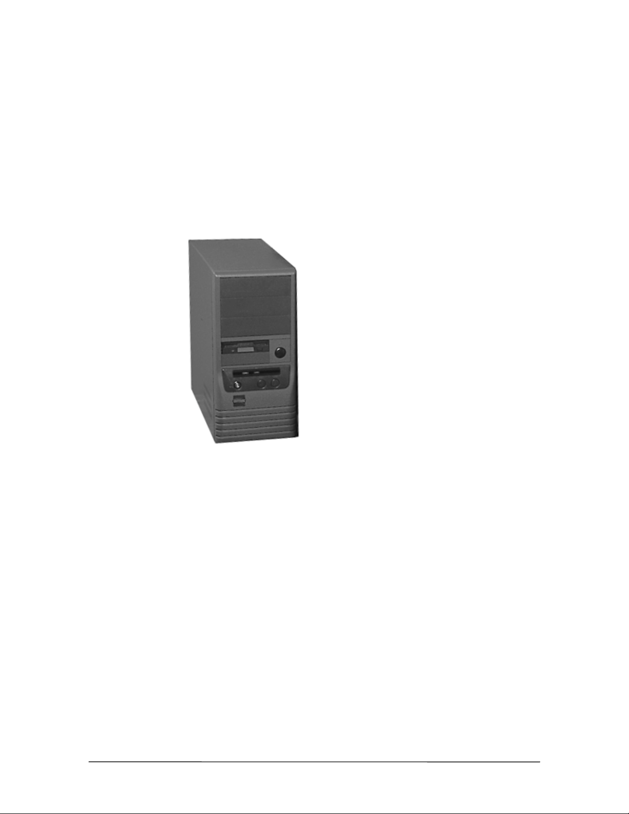
The Telecor Voice Server Model 200 (PV-CSU-200) is the central component of the Telecor VS1
telephone system. It houses the proprietary software and hardware that operates the system. The
TVS is a commercial, industrial-grade server that uses industry-standard hard drives and can store at
least 30 hours of voice messages. It comes equipped with a 56 Kbps modem for Remote System
Access (RSA), enabling you to make fast, reliable programming changes. The modem card is
identified by its two RJ-11 adapters. Only one modem can be installed in the TVS.
The TVS comes with a 32-port Host Adapter Card already installed. You can install a maximum of
four Host Adapter Cards in the TVS. For information on installing additional Host Adapter Cards,
see “Installing a Host Adapter Card,” page 35.
Telecor Voice
Server
Hardware Specifications
Dimensions (WxHxD): 5.75" x 14.75" x 13.75"
Weight: 27 lbs.
Power Requirements: 120 VAC
Temperature: 4°–38° C operational;
Humidity: 5%–95% non-condensing
Standards Compliance: FCC Part 15; UL1459
Power Consumption: max. 240VA
4 Hardware
Page 19
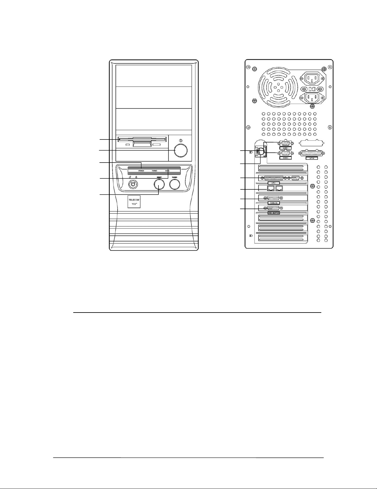
Floppy Disk drive
r
r
r
r
Front View Back View
On/Off button
Power LED
indicato
HDD LED Indicato
Reset button
TVS front
and back views
Serial Ports
Keyboard Port
VGA Monito
Port
Modem Port
Cable A (15-Pin)
Host Adapte
Cable (26-Pin)
I/O Port and IRQ Usage
The following tables list the I/O Port and Interrupt Request settings used by the Telecor VS1 phone
system.
IRQ Usage
0 System Timer
1 Keyboard
2 Cascade to second programmable Interrupt Controller
3COM 2
4COM 1
5 COM 3 (Internal RSA modem)
6 Floppy Drive
7LPT 2
8 Real-time Clock/Calendar
9 SC200 Switch Card
10 Available
11 Available (Default setting for Network Interface Card)
12 Reserved for PS/2 mouse port on current system board
13 Numeric Coprocessor
14 IDE Controller
15 SC200 Switch Card
VS1 Installation, Configuration & Operating Guide 5
Page 20

Port Address* Usage
210–21F System Timer
2F8–2FF COM 2
300–307 HA200 Host Adapter (ports 1–32)
308-30F HA200 Host Adapter (ports 33–64)
310–317 HA200 Host Adapter (ports 65–96) or T1 Interface Card 1
318–31F HA200 Host Adapter (ports 97–128) or T1 Interface Card 0
320–327 HA200 Host Adapter (ports 129–160)
328–32F HA200 Host Adapter (ports 161–192)
340–35F Network Interface Card
379–37B LPT 1
3E8–3EF COM 3
3F8–3FF COM 1
*All port addresses are listed in hexadecimal format.
6 Hardware
Page 21

Port Expansion Unit (PEU)
Each VS1 business telephone system requires one or more Port Expansion Units (PEUs) to which
all standard CO lines and station equipment are connected. Each PEU has 16 RJ-11 ports.
The first PEU is attached to the Telecor Voice Server (TVS). An additional PEU can be daisychained off the first PEU. The TVS comes with a 32-port Host Adapter Card from which a
maximum of two PEUs can be daisy-chained. To connect additional PEUs to the TVS, you must
install additional Host Adapter Cards. For more information on installing a Host Adapter Card, see
“Installing a Host Adapter Card,” on page 35. A maximum of 12 PEUs can be connected to the
TVS for a total of 192 ports.
Three PEU models are available as described below:
PEU 250
The Port Expansion Unit Model 250 (PV-PEU-250) contains 16 generic ports that you can
configure as CO or station ports. Ports are configured using pushbutton switches located next to
each port jack. Eighteen dual-color LEDs (amber and green) on the front of the PV-PEU-250
indicate power and communication status. The PV-PEU-250 includes integrated caller ID circuitry
on all 16 ports. Automatic cut-over is provided for ports 1 through 4 if the ports are configured as
CO ports. If a power failure occurs, the ports cut over to ports 5 through 8 respectively, if ports 5
through 8 are configured as extensions. The PV-PEU-250 can be used as any PEU in a system. It
does not contain external device contacts. External devices are connected to TVS via the Dry
Contact Unit Model 100 (PV-DCU-100).
Note If your current TVS software version is prior to 2.9, only the first eight ports on the Model
250 are configurable as CO lines.
PEU 205
The Port Expansion Unit Model 205 (PV-PEU-205) contains six external device contacts including
two zone pager outputs for overhead paging systems, two music inputs for music on-hold or
promotions on-hold, and two dry contact relays to attach electronic door locks, buzzers, or sirens.
The Model 205 typically serves as the first PEU on a system with Model 200 PEUs connected as the
second and additional PEUs. Of the 16 ports the first eight ports can be configured as CO ports or
station ports. The remaining eight ports can be configured as station ports only.
PEU 200
The Port Expansion Unit Model 200 (PV-PEU-200) has all the same features of the Model 205 but
it does not have the six external device contacts. The Model 200 typically serves as the second, and
additional PEU on systems using the Model 205 PEU as the first PEU. Of the 16 ports, the first
eight ports can be configured as CO ports or station ports. The remaining eight ports can be
configured as station ports only.
VS1 Installation, Configuration & Operating Guide 7
Page 22
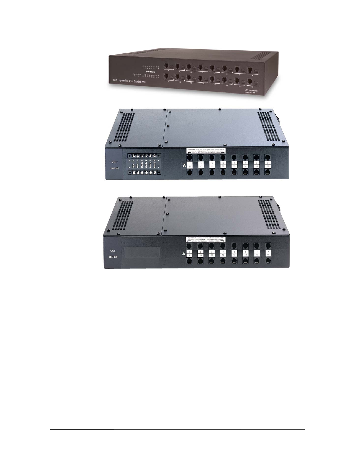
PEU 250
PEU 205
PEU 200
Hardware Specifications
Dimensions (WxHxD): 16.5" x 3" x 13.5"
Weight: 27 lbs.
Power Requirements: 120 VAC
Temperature: 4°–38° C operational;
Humidity: 5%–95% non-condensing
Standards Compliance: FCC Part 15, FCC Part 68; UL1950
Power Consumption: max 120VA
8 Hardware
Page 23
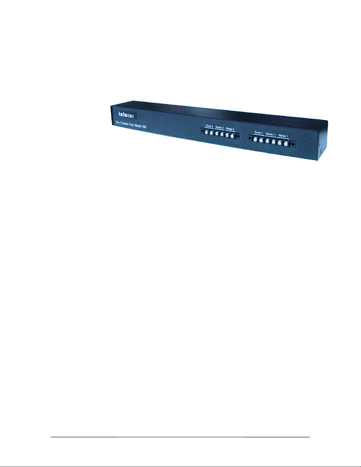
Dry Contact Unit (PV-DCU-100)
The Dry Contact Unit Model 100 (PV-DCU-100) is used to connect external contacts in systems
that use Model 250 Port Expansion Units. The PV-DCU-100 provides connections for two speakers
(zones), two music inputs, and two dry contact (relay) outputs. It is connected to the switch card in
the TVS.
PV-DCU-100
Hardware Specifications
Dimensions (WxHxD): 16.5" x 1.75” x 2.75”
Weight: 1 lb. 6 oz.
Power Requirements: No power required
Temperature: 4°–38° C operational;
Humidity: 5%–95% non-condensing
Standards Compliance: FCC Part 15, FCC Part 68; UL1950
VS1 Installation, Configuration & Operating Guide 9
Page 24
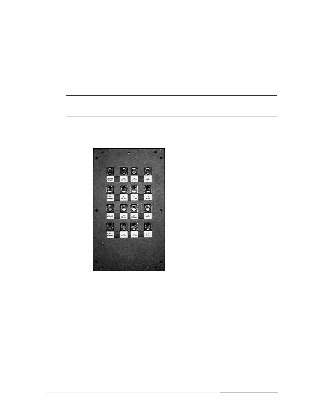
Cut-Over Box
An optional Cut-Over Box provides power failure transfer for up to four analog CO lines by routing
the CO lines directly to station sets on the VS1 telephone system. If you have a power failure or if
the Cut-Over Box is turned off, each station connected to the Cut-Over Box becomes a direct
outside line for incoming and outgoing calls. All phones used with the VS1 phone system can be
connected to a Cut-Over Box. Although the Cut-Over Box is an optional component, it is
recommended for all VS1 phone systems.
Note If your VS1 system uses the Port Expansion Unit Model 250, you do not need a separate
cut-over box. Cut-over functionality is built into the PEU Model 250.
Note When installing a new system, Telecor recommends that the Cut-Over Box cable
connections are made after the system has been installed, the software configured, and
all stations have been tested and verified. This aids in determining which stations will be
connected to the Cut-Over Box.
Cut-Over Box
Hardware Specifications
Dimensions (WxHxD): 5.75" x 9.75" x 3.7"
Weight: 5.5 lbs.
Power Requirement: 12 Vdc provided by included 120 VAC adapter
Temperature: 4°–38° C operational
Humidity: 5%–95% non-condensing
Adapter Specifications: RJ-11
Standards Compliance: FCC Part 15; UL1459
10 Hardware
Page 25
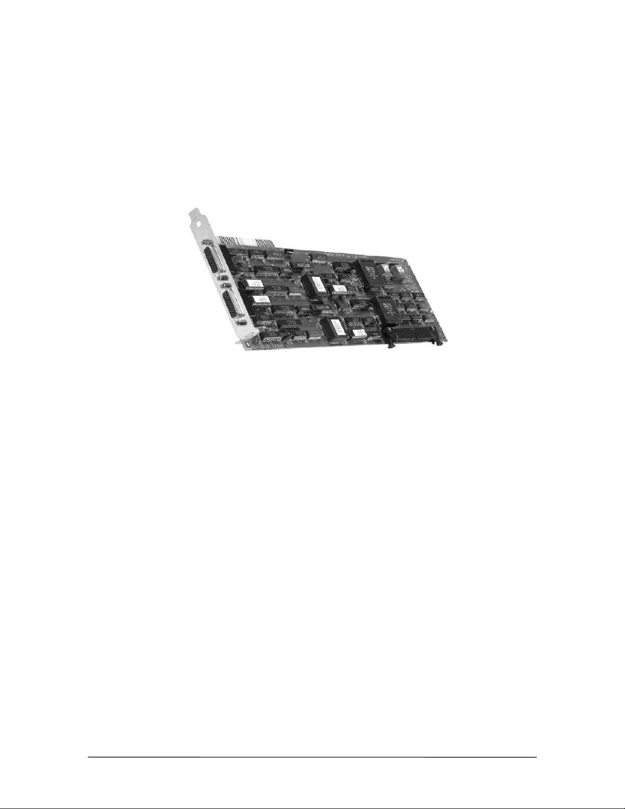
Host Adapter Cards
A Host Adapter Card is used to connect PEUs to the TVS. Each TVS comes with one 32-port Host
Adapter Card installed, meaning that it can support two 16-port PEUs. Additional Host Adapter
Cards can be installed in the TVS to increase the port capacity of the phone system.
Aside from the 32-port model Host Adapter Card, Telecor offers a 64-port model. The 64-port Host
Adapter Card supports four PEUs, giving you 16 ports per PEU for a total of 64 ports. Installing
three 64-port Host Adapter Cards expands the number of ports to 192.
64-Port Host
Adapter Card
Hardware Specifications
Dimensions: 13.5" x 4"
Weight:
32-Port Host Adapter Card: 9 oz.
64-Port Host Adapter Card: 10.3 oz.
Power Requirement: + 5 Vdc from ISA Bus
Adapter Specifications:
32-Port Host Adapter Card: One DB-26 Connector
64-Port Host Adapter Card: Two DB-26 Connectors
Architecture: 8-Bit Industry Standard Architecture (ISA)
Standards Compliance: FCC Part 15; UL1459
VS1 Installation, Configuration & Operating Guide 11
Page 26
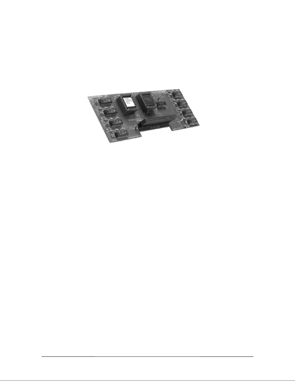
Caller ID Option Module
The Caller ID Option Module permits Caller ID (provided by local phone company) to work on the
Telecor VS1 phone system. The Caller ID Option Module requires Voice Server Software Version
2.7 or later. The Caller ID Option Module is installed inside a Port Expansion Unit Model 200 (PVPEU-200) or Port Expansion Unit Model 205 (PV-PEU-205). The Caller ID module is not used
with the Port Expansion Unit Model 250 (PV-PEU-250). The Model 250 contains integrated Caller
ID circuitry on all 16 ports.
The Caller ID
Option Module
Hardware Specifications
Dimensions: 7.25" x 2.5"
Weight: 3 oz.
Power Requirements: +5 Vdc and –5 Vdc, supplied by the PEU
Standards Compliance: FCC Part 68, UL1950
Adapter Specifications: 50-pin header connector
Architecture: Two-layer PCB
12 Hardware
Page 27
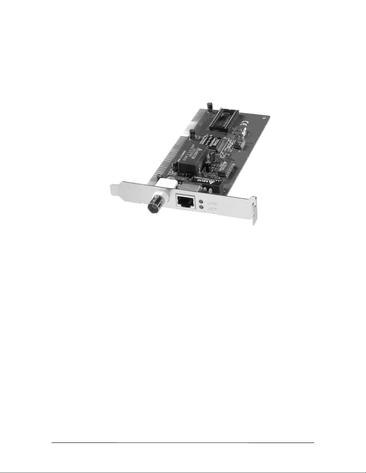
10Base-T Network Interface Card
Installing a 10Base-T Network Interface Card enables Station Message Detail Recording (SMDR)
data to be written a network server. The 10Base-T Network Interface Card must be installed in the
Telecor Voice Server (TVS) if you want to log on to a Novell
File and Print Services for Netware (FPNW).
®
network or an NT 4.0 server running
10Base-T Network
Interface Card
Hardware Specifications
Dimensions: 6.25" x 2.75"
Weight: 3.5 oz.
Power Requirement: + 5 Vdc from ISA Bus
Adapter Specifications: RJ-45 connector
Architecture: 16- Bit Industry Standard Architecture (ISA) bus
Standards Compliance: FCC Part 15 Class A
Compatibility: Novell® NE2000
VS1 Installation, Configuration & Operating Guide 13
Page 28
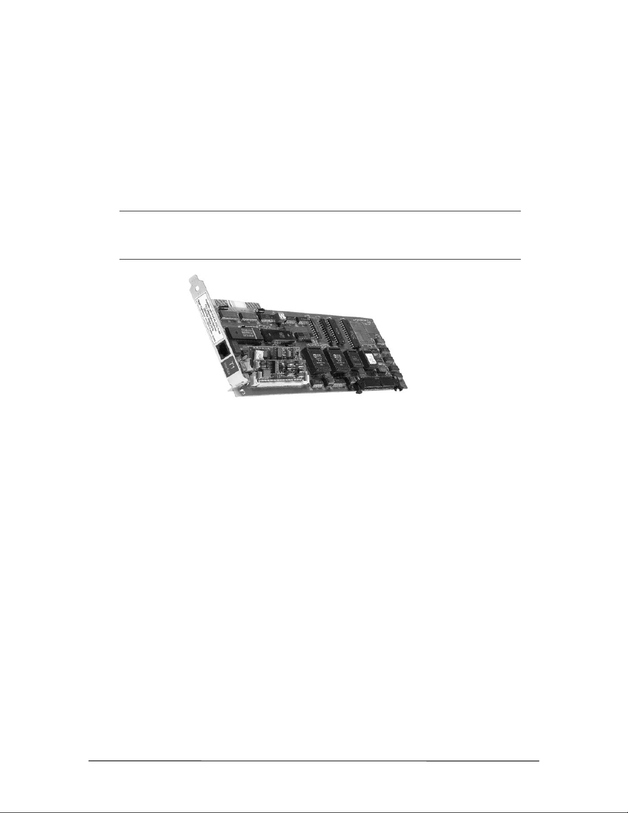
T1 Interface Card
T1 is a digital transmission link with the capacity of 1.544 Megabits per second (Mbps). T1 uses
two pairs of normal twisted wires, and can normally handle 24 simultaneous voice conversations.
The T1 Interface Card is installed inside the TVS and supports 24 T1 channels. The T1 Interface
Card supports E&M, DID, DNIS, ANI, Ground Start, and Loop Start. A maximum of two T1
Interface Cards can be installed in the TVS. The following table shows the number of T1 channels
and Analog CO lines that can be configured for each T1 card installed in the TVS.
Number of T1
Cards
T1 channels Maximum
0 0 12 96 192
1 24 10 72 184
2 48 8 48 176
T1 Interface Card
Hardware Specifications
Dimensions: 13.5" x 4"
Weight: 10 oz.
Power Requirement: +5 Vdc from ISA Bus
# of PEUs
Maximum
Analog CO lines
Maximum
Total Ports
Adapter Specifications: RJ-48
Architecture: 8-bit Industry Standard Architecture (ISA)
Standards Compliance: FCC Part 15; UL1459
14 Hardware
Page 29
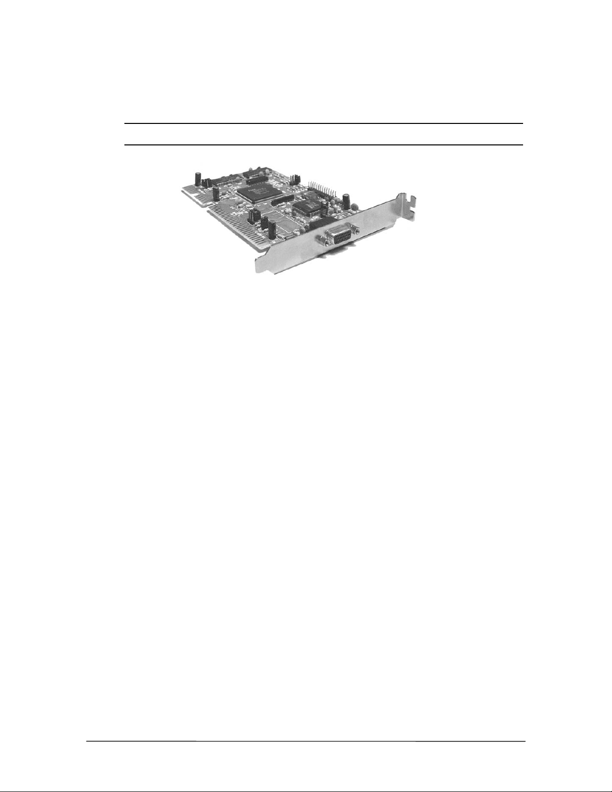
TVS VGA Video Card
The Telecor Voice Server (TVS) Model 200 includes a built-in VGA video card.
Note Even if you do not plan to connect a monitor to the system, the video card is required for
operation and must remain installed.
VGA
Video Card
Hardware Specifications
Dimensions: 6.25" x 3.75"
Weight: 3.2 oz.
Power Requirement: +5 Vdc from ISA Bus
Adapter Specifications: DB15 connector
Architecture: 16-Bit Industry Standard Architecture (ISA)
Standards Compliance: FCC Part 15
VS1 Installation, Configuration & Operating Guide 15
Page 30
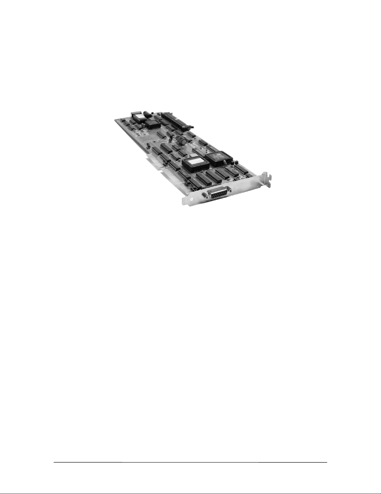
SC200 Switch Card
Each TVS comes with a preinstalled Switch Card, identified by its 15-pin connector labeled Cable
A. The primary functions of the Switch Card are to support call switching, zone paging, external
music on-hold sources, relay contacts, and the voice channels. It has a connection for an external fan
with a fan fault monitor. In addition it provides for monitoring of the case temperature. The switch
card is also responsible for processing system resets.
SC200 Switch Card
Hardware Specifications
Dimensions: 13.5" x 4"
Weight: 9 oz (258 grams)
Power Requirement: + 5 Vdc and (+12 Vdc from ISA Bus if external fan is connected)
Adapter Specifications: DB15 connector
Architecture: 16-Bit Industry Standard Architecture (ISA)
Standards Compliance: FCC Part 15; UL1459
16 Hardware
Page 31
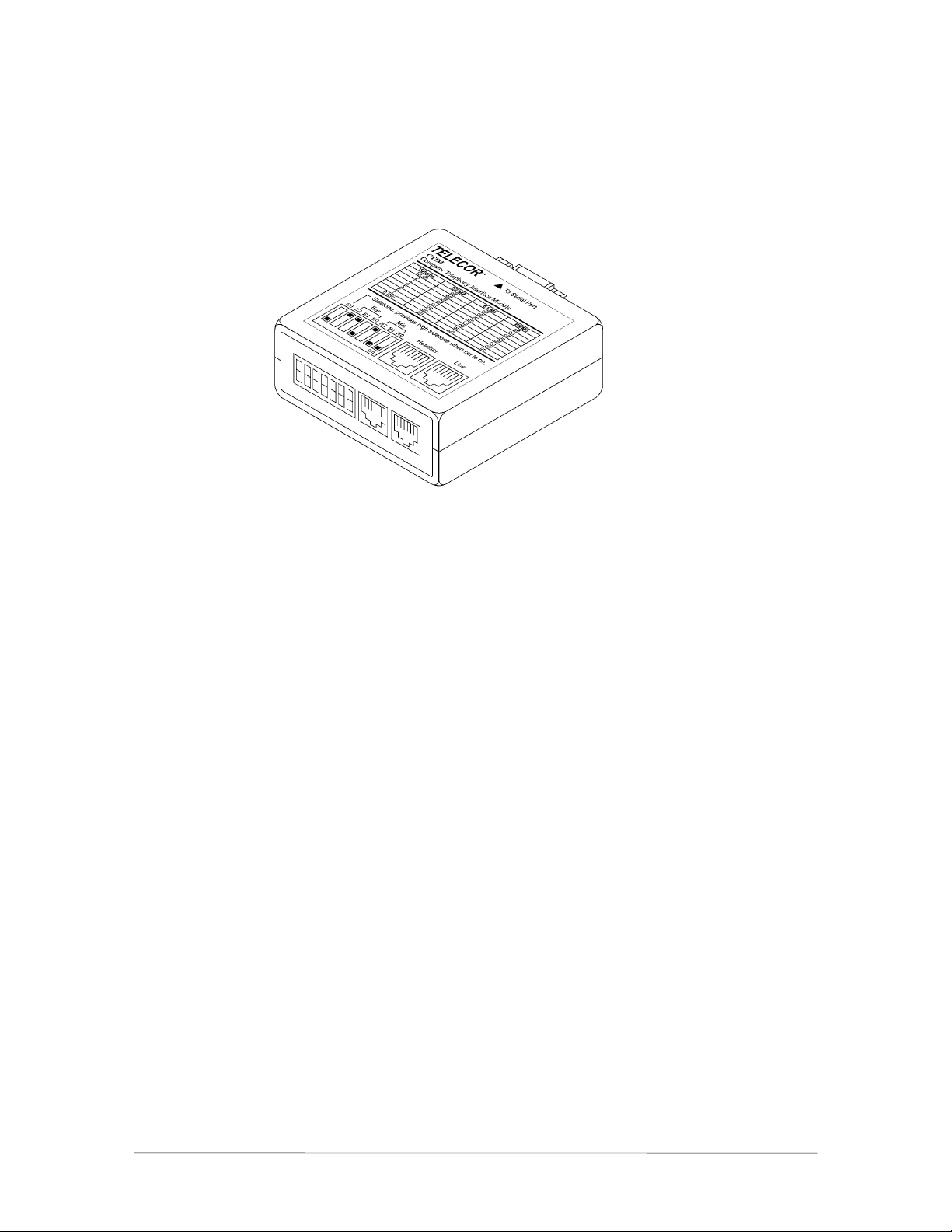
Computer Telephony Interface Module (CTIM)
The Computer Telephony Interface Module (CTIM) provides a digital interface to the VS1 phone
system for the Telecor Attendant and Connect applications. The CTIM is an external device with a
headset jack intended for use only with the VS1 phone system.
CTIM
Hardware Specifications
Dimensions: 2.6" x 2.6" x 1.1"
Weight: 2.8 oz.
Power Requirements: Powered by PEU
Temperature: 10°–50° C operational
Humidity: 5%–95% non-condensing operational
Adapter Specifications: DB-9 Serial Port; RJ-11 Line; RJ-22 Headset
VS1 Installation, Configuration & Operating Guide 17
Page 32
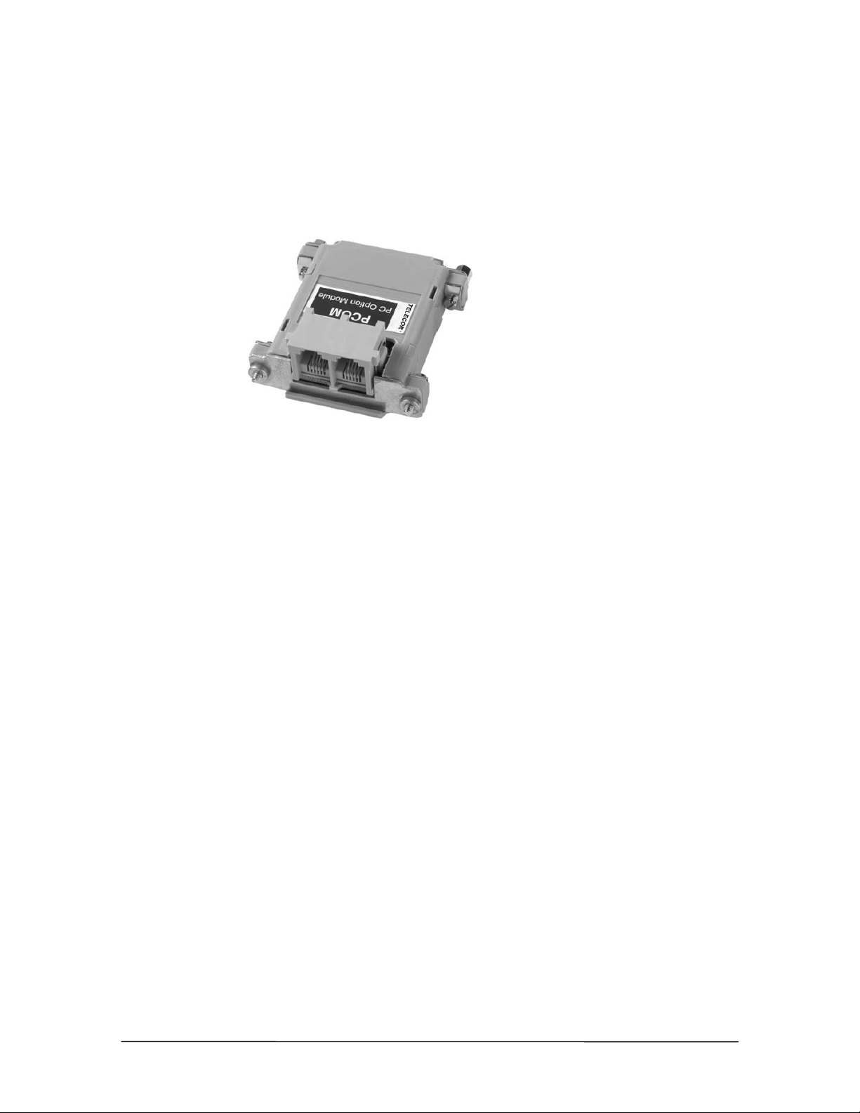
PC Option Module (PCOM)
The PC Option Module (PCOM) provides an externally connected serial interface to a computer for
data sent by the Telecor Voice Server (TVS). The PCOM is used with the Telecor Connect CTI
client application. By installing a PCOM, Telecor Connect users can use their computer screen for
call processing and keep the phone on their desk. Keeping a phone on the desk also allows calls to
be received when the computer is turned off.
PC Option Module
(PCOM)
(cable not pictured)
Hardware Specifications
Dimensions: 3.25" x 2.5"
Weight: 3 oz.
Power Requirements: Powered by PEU
Temperature: 10°–50° C operational
Humidity: 5%–95% non-condensing operational
Adapter Specifications: RJ-11 connectors and one DB25 connector
18 Hardware
Page 33

ACD Status Board
The ACD Status Board provides a display of selected ACD groups and their status. The ACD Status
Board can be hung on a wall or placed on a solid surface at eye-level for easy viewing. The ACD
Status Board allows supervisors to monitor the progress of calls through the ACD and make
necessary changes quickly to ACDs requiring additional agents. The ACD Status Board can be
customized to display a single ACD group, scroll through all active ACD groups, or display no
ACD groups.
Installation and setup of the ACD Status Board is quick and straightforward. No additional hardware
or software needs to be installed on the Telecor Voice Server (TVS) or the Port Expansion Unit
(PEU). The ACD Status Board is connected to the VS1 business telephone system through the ACD
Status Phone. The ACD Status Phone is functionally identical to the Display Phone Model 200
(DP200), except that the display is customized to monitor ACD status. The ACD Status Board
serves as an external monitoring display of the ACD Status Phone.
The ACD Status Board Option Kit includes the ACD Status Phone and an ACD Status Board
connection cable. The ACD Status Board itself must be purchased from Spectrum, the Board’s
manufacturer, or from a Spectrum dealer.
ACD Status Board
and ACD Status
Phone
ACD Status Board Manufacturer
Product Number: DAS-1512R1
Spectrum
10048 Easthaven Blvd.
Houston, TX 77075
800.392.5050
Please contact Spectrum or a Spectrum authorized dealer, to purchase the Board. This product is not
available from Telecor Inc.
VS1 Installation, Configuration & Operating Guide 19
Page 34
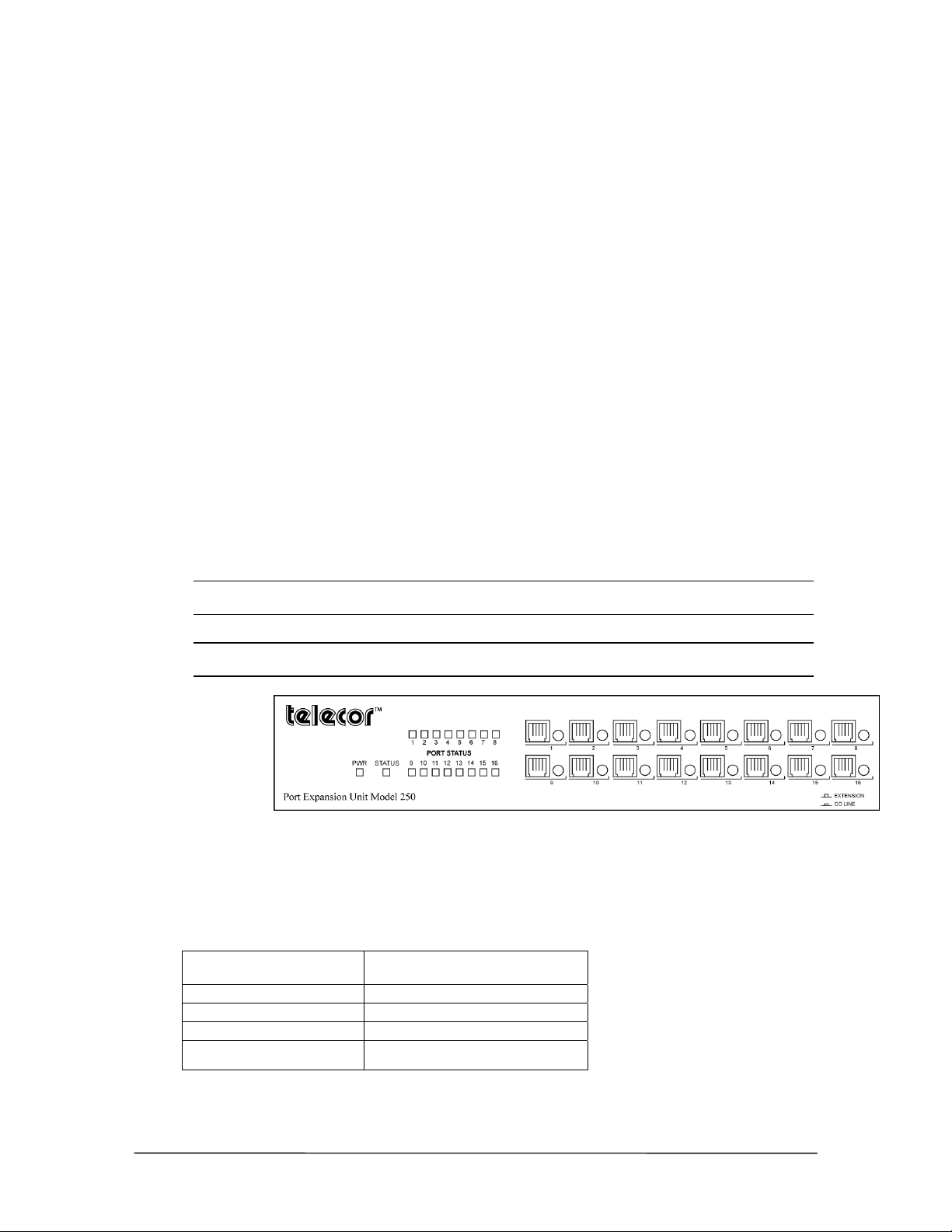
HARDWARE CONFIGURATION & INSTALLATION
This section contains instructions and figures to configure and install the VS1 phone system
hardware.
The Telecor VS1 telephone system can be either rack mounted or wall mounted. Each PEU comes
with brackets for a wall mount and rack mount setup. Mounting hardware for other components is
ordered depending if a wall mount or rack mount setup is used. Prior to mounting the equipment, the
PEUs must first be considered to support CO Lines or Station Extensions.
Configuring the PEU 250
The Model 250 PEU has 16 ports, each of which can be configured as a CO or Station port. It is
recommended that the PEU 250 serve as the first PEU on the system, as it is labeled with ports 1 to
16. Ports are addressed sequentially by the TVS. When configuring more than one PEU, verify that
each port is correctly identified before changing switch settings.
To configure the PEU 250:
1. Use the pushbutton switches next to each port jack to set the port as a CO Line or Extension.
• CO Line = button in
• Extension = button out
Note: If your current software version is prior to 2.9, only the first eight ports on the PEU Model
250 are configurable as CO lines.
Note: In order for Caller ID to work on Ports 1 - 8, Port 1 must be set as a CO Port. In order for
Caller ID to work on Ports 9 – 16, Port 9 must be set as a CO Port.
Front view of
PEU 250
Cut-Over Functioning on the PEU 250
The PEU 250 provides power failure cut-over functioning for up to four analog CO lines by routing
the CO lines directly to station sets on the VS1 telephone system. A Port from 1 through 4
configured as a CO Line will cut over to an associated Port from 5 through 8, respectively, if
configured as an Extension.
Port configured as
CO Line
1 5
2 6
3 7
4 8
Cuts over to Port if configured as
Extension
20 Hardware
Page 35
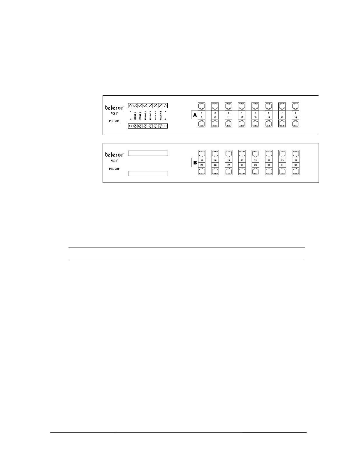
Configuring the PEU 205 and 200
Each PEU 205 and PEU 200 has 16 ports. Ports 1–8 can be configured as either CO lines or stations.
Ports 9–16 are for stations only. Ports are addressed sequentially by the TVS. When configuring
more than one PEU, verify that each port is correctly identified before changing switch settings. It is
recommended that the PEU 205 serve as the first PEU on the system.
PEU 205 Ports
1-16 and
PEU 200 Ports
17-32 (front view)
To configure the PEU 205 or PEU 200:
1. Attach the correct PEU labels between the RJ-11 jacks on the front of each PEU. Label the first
PEU with ports 1-16 and the second PEU with ports 17–32, and so on. It is recommended that
the PEU 205 serve as the first PEU on the system.
2. Remove the top panel on the PEU.
WARNING! Do not remove the smaller (top) panel, which covers the power supply. The power
supply area contains hazardous voltages and has no adjustable settings.
3. Locate the station/CO jumper sets for Port 1. There are eight blocks of pins. Each contains
black blocks for analog, blue blocks for digital, and red blocks for remote power.
• Ports 1–8 have both station and CO jumper sets.
• Ports 1–4 are preset as CO ports and Ports 5–8 are set as station ports. Up to four
additional CO ports can be configured by repositioning the jumpers on Ports 5–8.
• Ports 9–16 do not have jumpers.
VS1 Installation, Configuration & Operating Guide 21
Page 36
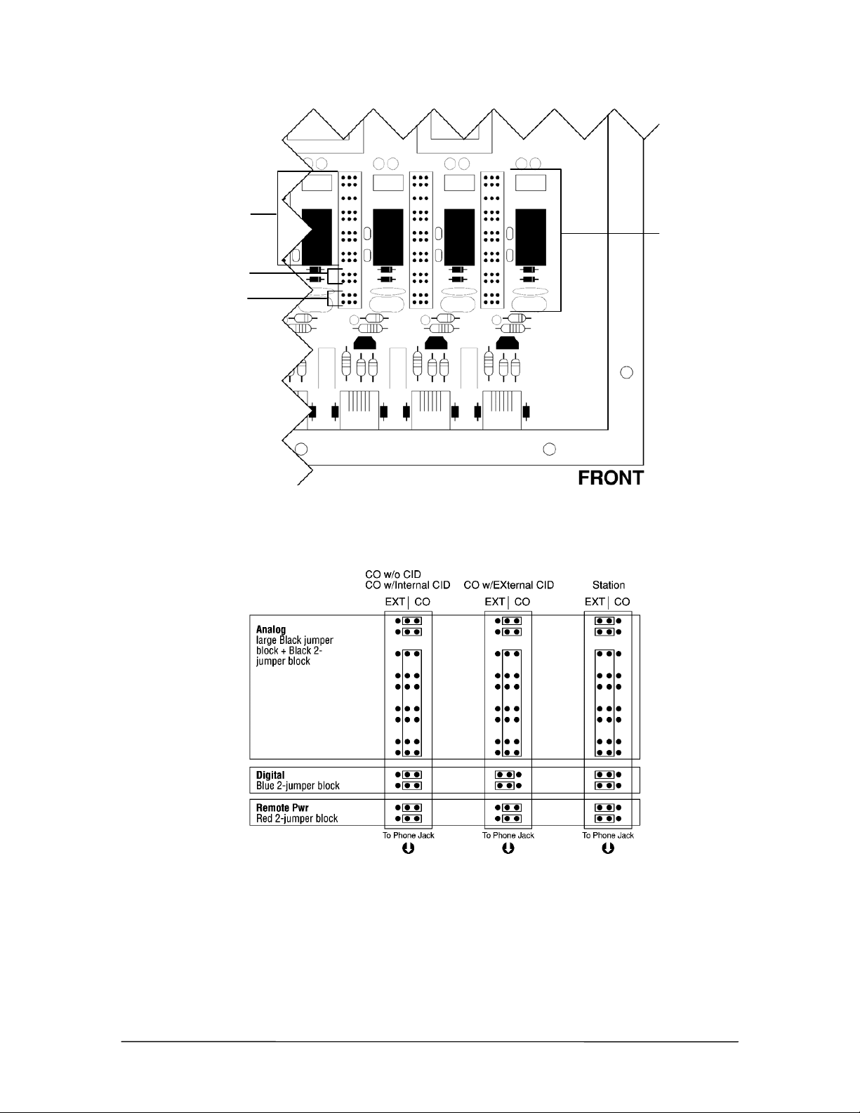
Analog (black)
Remote Power (red)
Jumpers inside
the PEU
4. Set the jumpers for Port 1 based on the diagram below. Move all jumpers to the left side for a
Port 1 jumper settings
Digital (blue)
station. Move all Analog (black) and Remote Power (red) jumpers to the right side for CO
ports, and set the digital (blue) jumpers based on having Internal Caller ID or External Caller
ID.
Jumper Settings
5. Repeat Steps 3 and 4 to set the jumpers for Ports 2–8.
6. When finished, replace the panel on the PEU.
7. Repeat Steps 1-6 for additional PEUs.
22 Hardware
Page 37
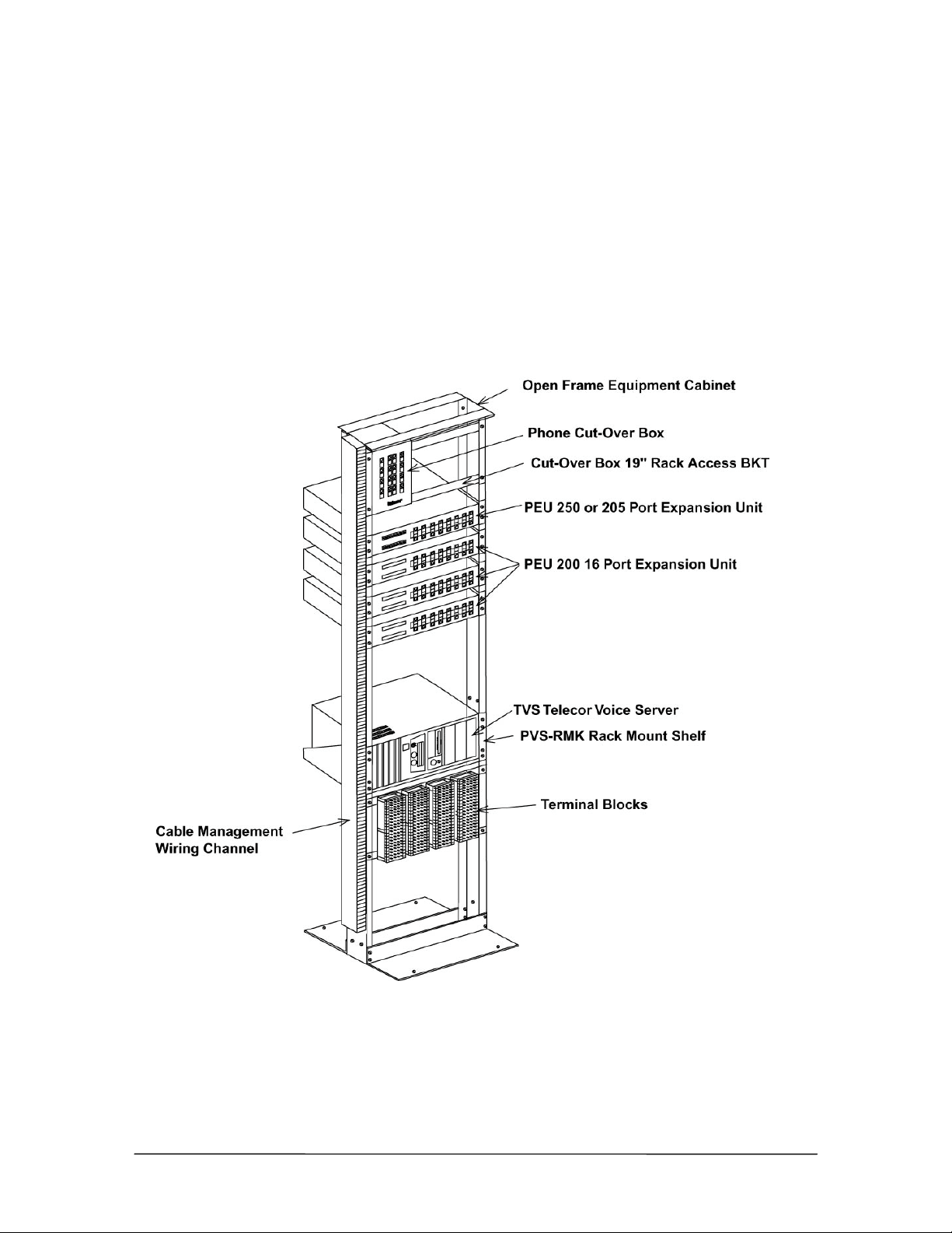
Rack Mount Setup
The Phone Cut-Over Boxes are located at the top of the rack. The PEU-250 or 205 is located
directly below the Cut-Over Box, followed by the PEU-200 units. The CO lines from the Telco
Demarc terminate onto the Cut-Over Boxes. Connections are then made with RJ11 patchcords from
the Cut-Over Box to the CO Ports on the PEU-250 or PEU 205 (see “Connecting the Cut-Over
Box,” page 33). If your installation does not include Cut-Over Boxes, then simply connect the CO
lines to the designated CO ports on the PEU 250 or PEU 205.
Station field wiring and Telco Demarc lines are terminated onto TM-16X3 or TM-8X3 terminal
blocks (see “Terminal Blocks,” page 25). The terminal blocks may be located on the equipment
rack.
VS1 Installation, Configuration & Operating Guide 23
Page 38
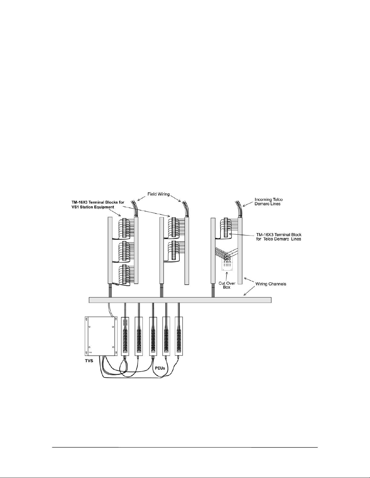
The TVS is located at the bottom portion of the rack and conveniently mounts into a PVS-RMK
Rack Mount Shelf. The TVS must be located no more than three feet away from the PEU-250 or
PEU 200.
Wall Mount Setup
The Phone Cut-Over Boxes are located adjacent to the incoming Telco Demarc lines, which
terminate onto the Cut-Over Boxes. Connections are then made with modular patchcords from the
Cut-Over Box to the CO Ports on the PEU-250 or PEU 205 (see “Connecting the Cut Over Box,”
page 33). If your installation does not include Cut-Over Boxes, then simply connect the CO Lines to
the designated CO ports on the PEU-250 or PEU 205.
Station field wiring and Telco Demarc lines are terminated onto TM-16X3 or TM-8X3 terminal
blocks (see “Terminal Blocks,” page 25). Telecor recommends that the terminal blocks be arranged
in an orderly manner on a plywood sheet mounted onto the wall. DO NOT MOUNT ANY
EQUIPMENT DIRECTLY ON DRYWALL SURFACES. Wiring channels should be used to
neatly house all the field wiring.
The TVS must be located no more than three feet away from the PEU-250 or PEU-205.
24 Hardware
Page 39
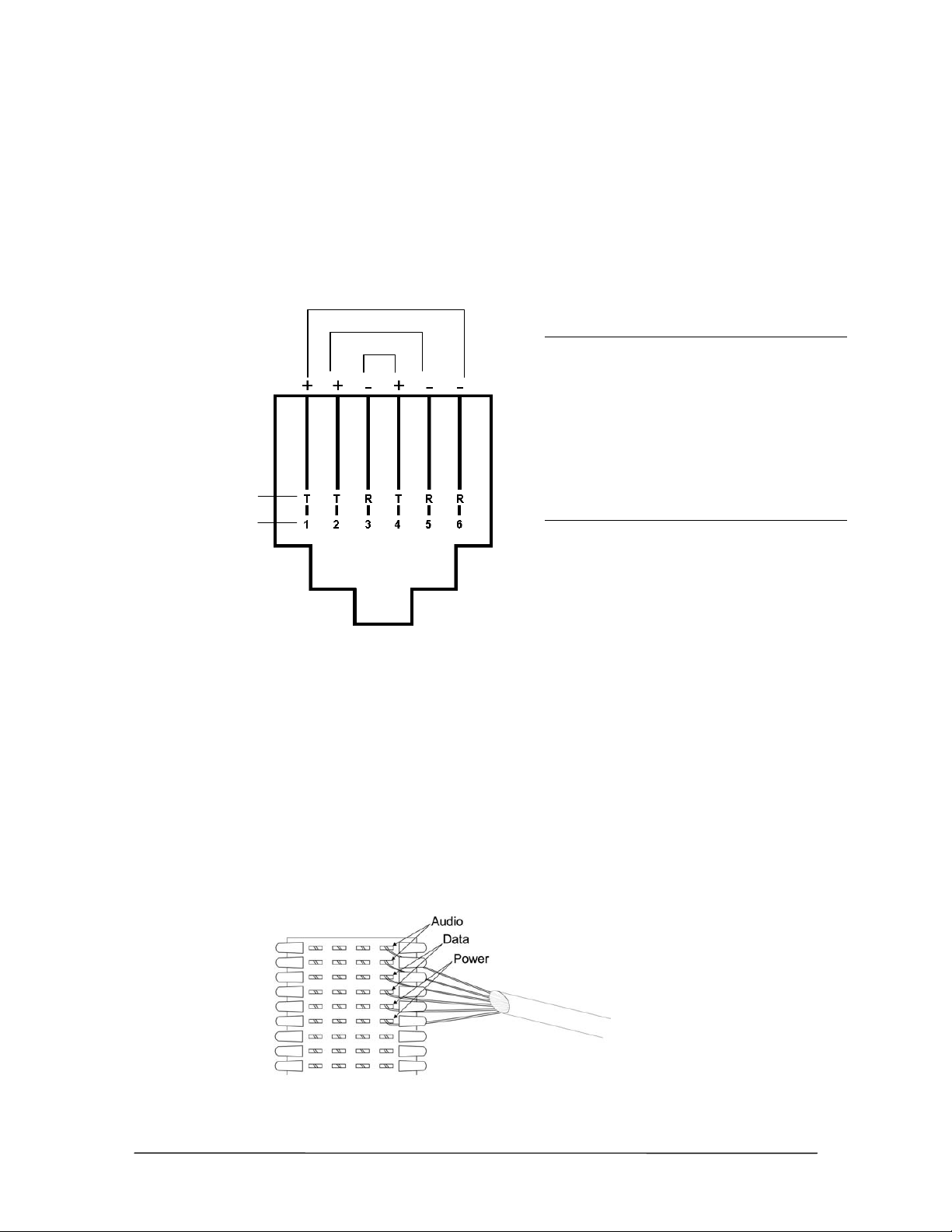
PEU Wiring Requirements
r
Each port on the PEU supplies remote power to display phones, and requires the use of 3-pair
wiring to connect the station to the PEU. For all other extensions, the PEU requires 2-pair wiring.
All ports are universal, enabling you to use any station option.
USOC is the wiring standard that should be followed for installing the VS1 phone system. Wiring
should adhere to the color code for USOC 6 conductor telecommunication lines as shown in the
diagram below.
Pair 3
Pair 2
Pair 1
Cable Jack
White w/ blue stripe Green
Blue w/ white stripe Red
White w/ orange stripe Black
Orange w/ white stripe Yellow
White w/ green stripe White
Green w/ white stripe Blue
Tip & Ring
designations
Pair Signal
Jack pin numbe
designations
Pair 1 Analog/Voice
Pair 2 Digital
Pair 3 Remote Power
USOC wiring
Terminal Blocks
The Prewired 66 Blocks with Modular Telephone Jacks should be used for interconnection between
the RJ11 jacks of the PEUs and the station field wiring and Telco Demarc lines. Each CO or station
line from the terminal block is connected to the corresponding CO or station port on the PEU with
an RJ11 patchcord. Two versions of termination blocks are available:
• TM-8X3 contains 8 RJ11 telephone jacks for connection of 8 stations or CO lines. Only one
side of the termination block is used. The other side is unconnected and can be used for cross
connects.
• TM-16X3 contains 16 RJ11 telephone jacks for connection of 16 stations or CO lines. Both
sides of the termination block are used. This conveniently corresponds with a 16-port PEU.
Terminal Block
Wiring
VS1 Installation, Configuration & Operating Guide 25
Page 40
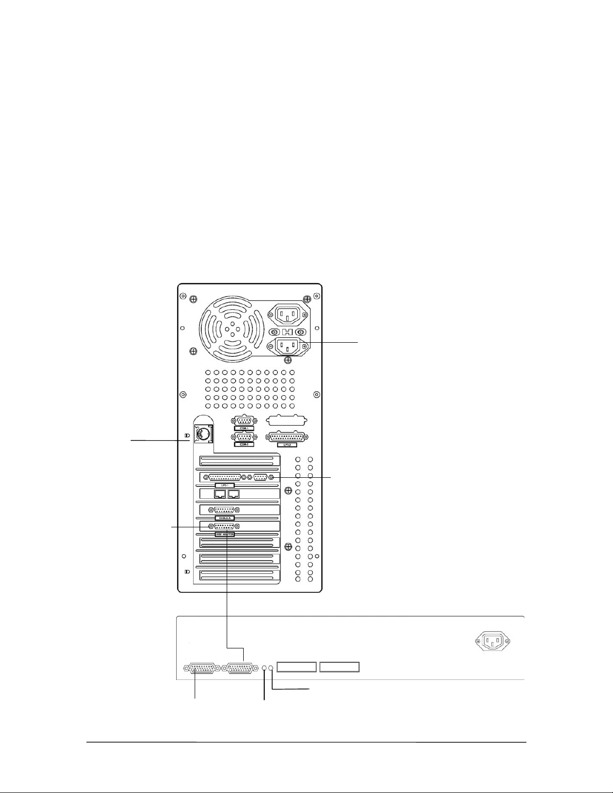
Connecting the Telecor Voice Server (TVS)
)
r
TVS to PEU 250
The diagram shows the correct port for each cable on the TVS and PEU 250. To connect the TVS
to the first PEU 250, complete the following steps.
1. Plug one end of the 26-pin data cable in the Host Adapter port on the TVS; plug the other end
of the 26-pin data cable in the Host Adapter port on the PEU.
2. Plug the Power cord into the TVS, and then connect it to a power strip.
• The Power LED on the PEU 250 is lit green to indicate that the power is on.
• The Status LED on the PEU 250 is lit green to indicate that the PEU is connected to the
TVS.
3. Plug in a keyboard and VGA monitor. This is required to create an emergency boot floppy
(page 47).
Back View
Plug in the Power Cord
Plug in a
Keyboard
Host Adapte
Cable (26-Pin)
Back View
Connecting the TVS
to the PEU 250
Next PEU
Plug in a VGA monitor
Connect the Host Adapter Cable (26-Pin
Power LED
Status LED
26 Hardware
Page 41
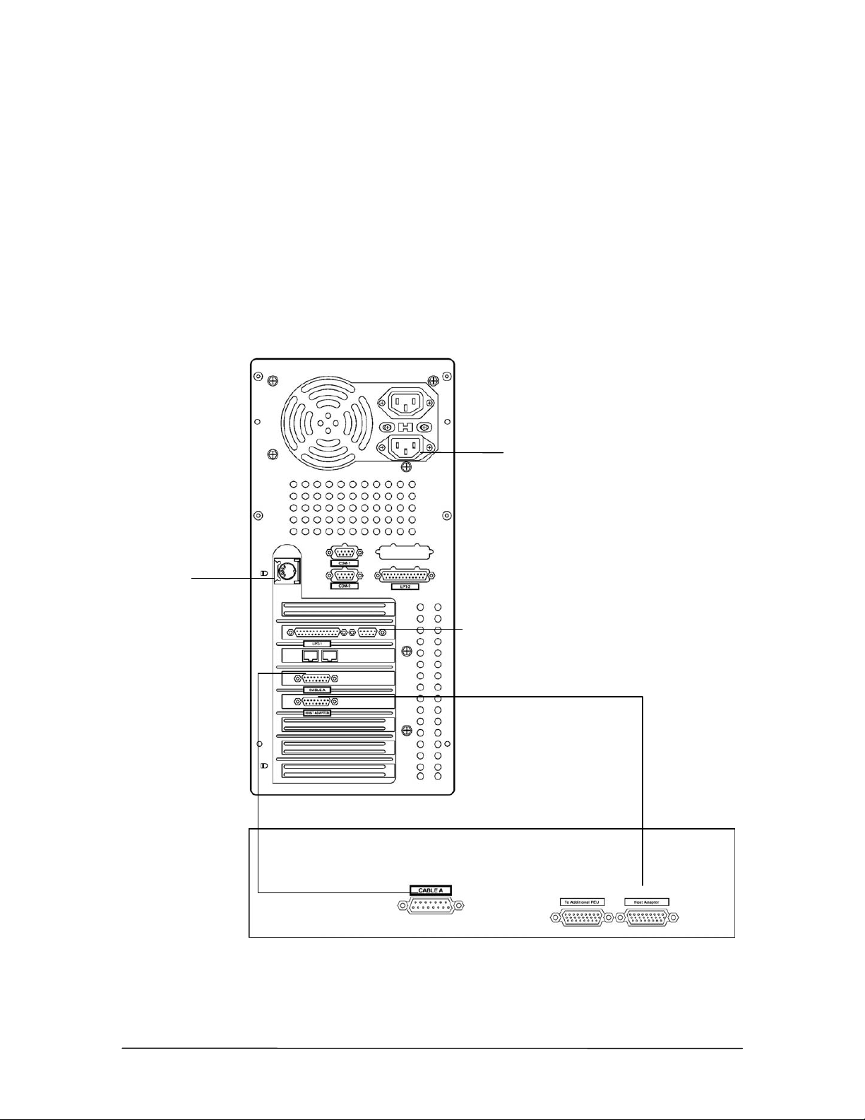
TVS to PEU 205
The diagram below shows the correct port for each cable on the TVS and PEU 205. To connect the
TVS to the PEU 205, complete the following steps.
1. Plug one end of the 15-pin cable in the Cable A jack on the TVS; plug the other end of the 15-
pin cable in the Cable A jack on the PEU.
2. Plug one end of the 26-pin data cable in the Host Adapter port on the TVS; plug the other end
of the 26-pin data cable in the Host Adapter port on the PEU.
3. Plug the Power cord into the TVS, and then connect it to a powerstrip.
4. Plug in a keyboard and VGA monitor. This is required to create an emergency boot floppy
(page 47).
Back View
Plug in the Power Cord
Plug in a
Keyboard
Program the T1
Interface Card using
the T1 Edit program
in Tel-Site.
Side View
Connecting the TVS
to the PEU 205
Plug in a VGA monitor
Connect the Host Adapter Cable (26-Pin)
Next PEU
Cable A (15-Pin)
VS1 Installation, Configuration & Operating Guide 27
Page 42
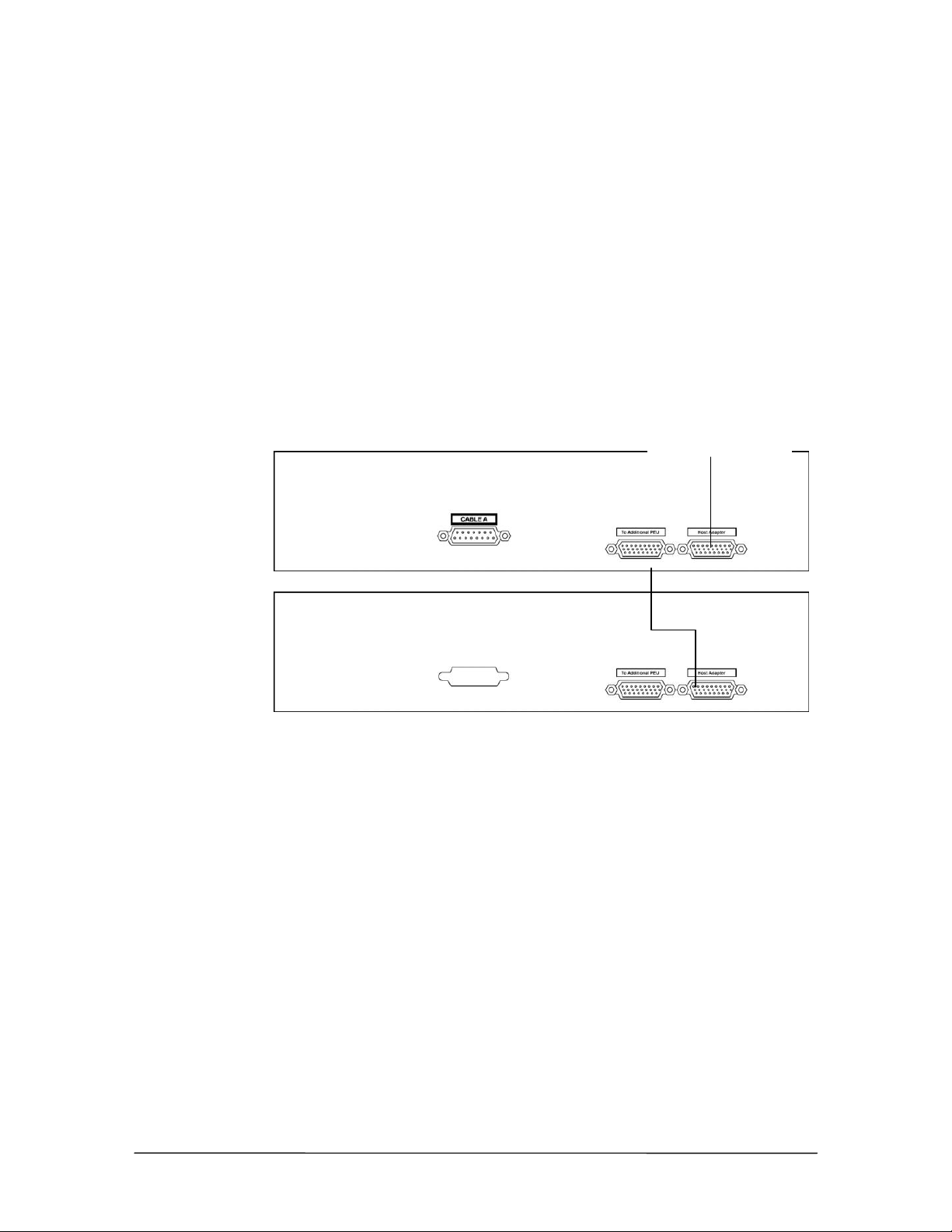
Installing Additional PEUs
Up to 11 additional PEUs can be added to your VS1 phone system to increase the number of
available ports to 192. An additional PEU can be daisy-chained off the first PEU. The first PEU
(odd numbered) is always connected directly to the Host Adapter Card inside the TVS, and the
second PEU (even numbered) is daisy chained from the first PEU. To add more than two PEUs, you
must install additional Host Adapter Cards. For information on installing a Host Adapter Card, see
“Installing a Host Adapter Card,” page 35.
To daisy chain a second PEU off the first PEU, complete the following steps:
1. Connect PEU 1 to the Host Adapter port on the TVS, as described on page 26.
2. Plug a 26-pin data cable in the To Additional PEU port of PEU 1.
3. Plug the other end of the 26-pin data cable in the Host Adapter port on PEU 2.
To Host Adapter Port
on the TVS
Side
View
Side
View
Daisy-chaining a
second PEU from
the first PEU
If you want to add a third PEU, install an additional Host Adapter Card in the TVS, and then
connect the third PEU to the second Host Adapter port on the TVS. Odd-numbered PEUs (PEU 1, 3,
5, 7, 9, 11) must always be connected to a Host Adapter card in the TVS, and even-numbered PEUs
(PEU 2, 4, 6, 8, 10, 12) are daisy-chained off the odd-numbered PEUs.
28 Hardware
Page 43
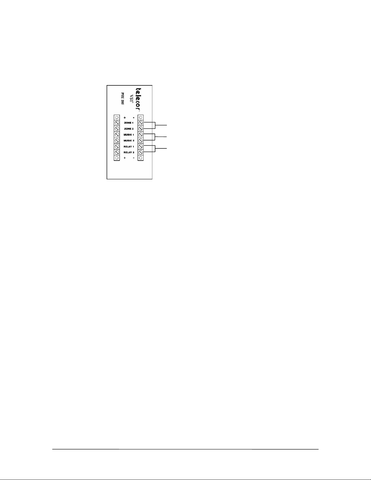
External Contacts – PEU 205
The Port Expansion Unit Model 205 has six external contacts including two zone pager outputs, two
music source inputs, and two dry contact relays. The following pages explain how to set up each of
the external contacts.
Zone Pager Outputs
Music Inputs
Relay Outputs
PEU 205 external
contacts
Connecting Zone Pager Outputs on a PEU 205
The Zone Pager contacts enable you to connect overhead paging systems to the
VS1 phone system. It provides a 600 ohm, low-impedance signal. To connect an overhead paging
system to the Telecor VS1 phone system, complete the following steps.
1. Connect a cable (with spade connectors or bare wire) to the “Input” jacks on the paging
equipment. The Model 205 accepts spade connectors, number 6 stud, or bare wire. Use 24gauge wire or larger.
2. Match the negative and positive connectors to the correct jacks on the Model 205.
3. Use a phone connected to the Telecor VS1 phone system to make a test announcement and then
adjust the volume level on the paging equipment as necessary.
Connecting Music Inputs on a PEU 205
The music inputs are for audio sources such as radios, music services, tape players, or CD players.
They are used for music on-hold and promotions on-hold. Each CO port can be configured for a
specific music source. CO ports can also be configured to play digital recordings stored on the TVS
hard drive. The music inputs on the Model 205 accept 600 ohm, low-impedance signals. To connect
a device to the music inputs on the VS1 phone system, complete the following steps:
1. Use a spade connector, number 6 stud, or bare wire to connect the device to the music source
input on the Model 205. Use 24-gauge wire or larger.
• The cable must be connected to the “Output” jacks on the music source.
2. Connect the ground wire to the negative input terminal on the PEU 205, and then connect the
insulated wire to the positive input terminal on the PEU 205. Contact Telecor Technical
Support for more information.
VS1 Installation, Configuration & Operating Guide 29
Page 44
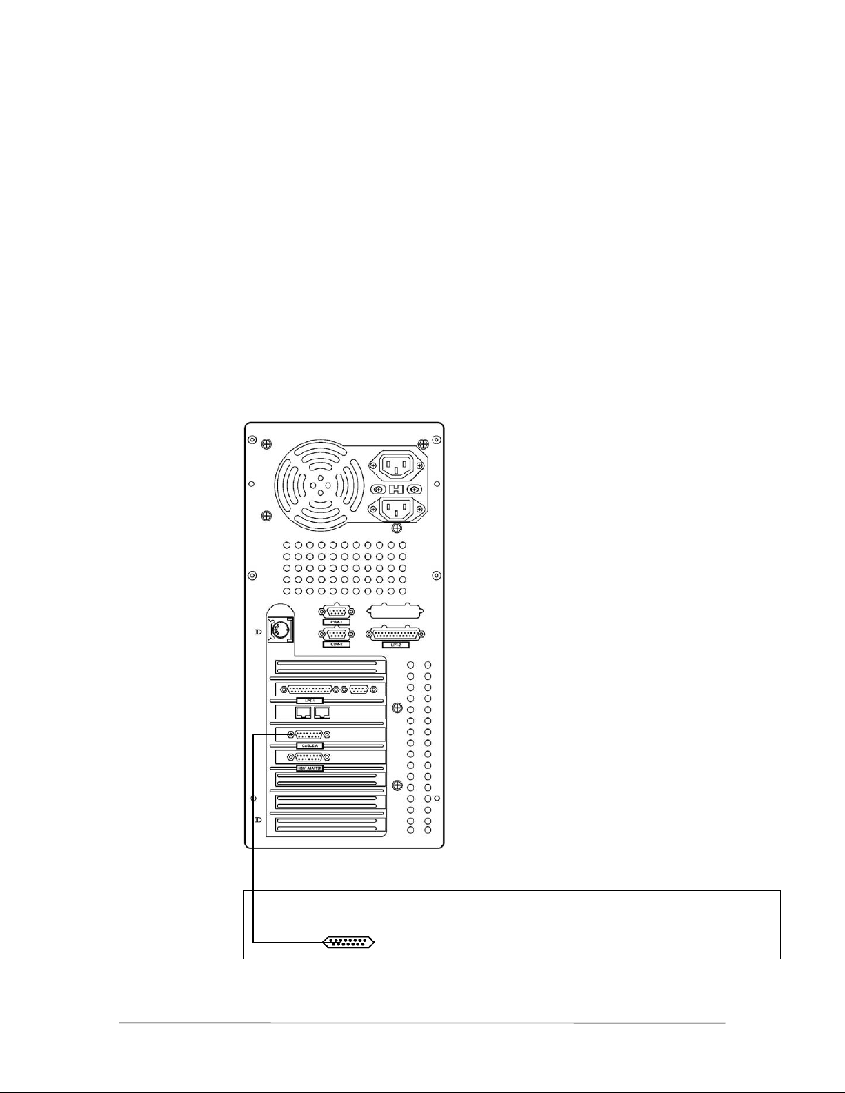
Connecting Relay Outputs on a PEU 205
The dry contact relays can be used to attach devices such as electronic door locks, sirens or buzzers.
These devices are controlled by dialing a DTMF code from any station. Follow these general
guidelines when connecting devices to the dry contact relays.
• Each relay output is normally open and completely isolated from the VS1 phone system and
from ground.
• The maximum open circuit voltage for either contact is 24 volts AC or DC. The maximum
current switched by either contact is 0.5 amps.
Installing the Dry Contact Unit Model 100
To connect the TVS to the DCU, complete the following steps.
1. Plug one end of the 15-pin cable in the Cable A jack on the TVS.
2.
3. Plug the other end of the 15-pin cable in the Cable A jack on the PEU.
Back View
Back View
Cable A (15-Pin)
Connecting the DCU
to the TVS
30 Hardware
Page 45

External Contacts – Dry Contact Unit Model 100
The Dry Contact Unit Model 100 has six external contacts including two zone pager outputs, two
music source inputs, and two dry contact relays. The following pages explain how to set up each of
the external contacts.
Model 100 external
contacts
Connecting Zone Pager Outputs on a DCU
The Zone Pager contacts enable you to connect overhead paging systems to the VS1 phone system.
It provides a 600 ohm, low-impedance signal.
To connect an overhead paging system to the VS1 phone system, complete the following steps.
1. Connect a cable (with spade connectors or bare wire) to the “Input” jacks on the paging
equipment. The DCU accepts spade connectors, number 6 stud, or bare wire. Use
24-gauge wire or larger.
2. Match the negative and positive connectors to the correct jacks on the DCU.
3. Use a phone connected to the Telecor VS1 phone system to make a test announcement and then
adjust the volume level on the paging equipment as necessary.
Connecting Music Inputs on a DCU
The music inputs are for audio sources such as radios, music services, tape players, or CD players.
They are used for music on-hold and promotions on-hold. Each CO port can be configured for a
specific music source. CO ports are also configurable to play digital recordings stored on the TVS
hard drive. The music inputs on the DCU accept 600 ohm, low-impedance signals.
To connect a device to the music inputs on the VS1 phone system, complete the following steps:
1. Use a spade connector, number 6 stud, or bare wire to connect the device to the music source
input on the DCU. Use 24-gauge wire or larger.
• The cable must be connected to the “Output” jacks on the music source.
2. Connect the ground wire to the negative input terminal on the DCU, and then connect the
insulated wire to the positive input terminal on the DCU. Contact Telecor Technical Support for
more information.
Connecting Relay Outputs on a DCU
The dry contact relays are used to attach devices such as electronic door locks, sirens, or buzzers.
These devices are controlled by dialing a DTMF code from any station. Follow these general
guidelines when connecting devices to the dry contact relays.
• Each relay output is normally open and completely isolated from the VS1 phone system
and from ground.
VS1 Installation, Configuration & Operating Guide 31
Page 46

• The maximum open circuit voltage for either contact is 24 volts AC or DC. The
maximum current switched by either contact is 0.5 amps.
Installation Checklist
Configure each PEU by setting the jumper settings for each port.
Mount the PEU to the wall or in the 7' x 19" rack.
Use the cables to connect the TVS to the first PEU, and then mount the TVS.
Connect additional PEUs by installing additional Host Adapter Cards and then daisy
chaining them from the first PEU.
Connect external contacts
32 Hardware
Page 47
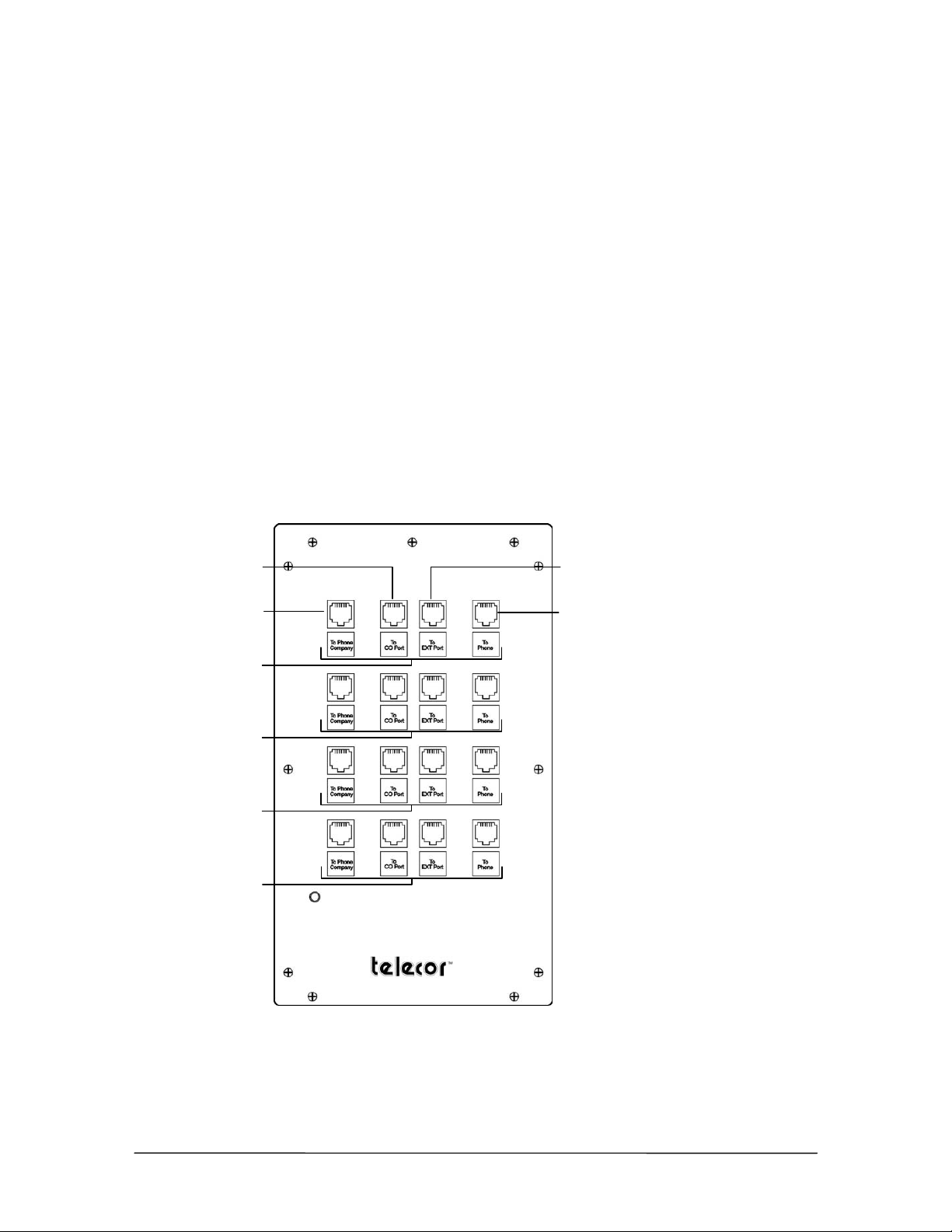
Connecting the Cut-Over Box
When installing a new system, Telecor recommends that the Cut-Over Box cable connections are
made after the system has been installed, the software configured, and all stations have been tested
and verified. This aids in determining which stations will be connected to the Cut-Over Box. To
connect the Cut-Over Box, complete the following steps:
1. Disconnect the RJ-11 cable from the first CO port on the PEU, and then plug it into Port 1 (To
Phone Company) on the Cut-Over Box.
2. Use a second RJ-11 Cable to connect the first CO port on the PEU to Port 2 (To CO Port) on
the Cut-Over Box.
3. Disconnect the RJ-11 cable from the first Station port on the PEU, and then plug it in to Port 4
(To Phone) on the Cut-Over Box.
4. Use a third RJ-11 cable to connect the first Station port on the PEU to Port 3 (To Extension
Port) on the Cut-Over Box.
5. Repeat Steps 1-4 for each CO line by using each row on the Cut-Over Box.
Front View
Port 2 (to CO port
on the PEU)
Port 1 (CO line)
Cut-Over Box
Port 3 (to Extension
port on the PEU)
Port 4 (To station)
Row 1
Row 2
Row 3
Row 4
VS1 Installation, Configuration & Operating Guide 33
Page 48
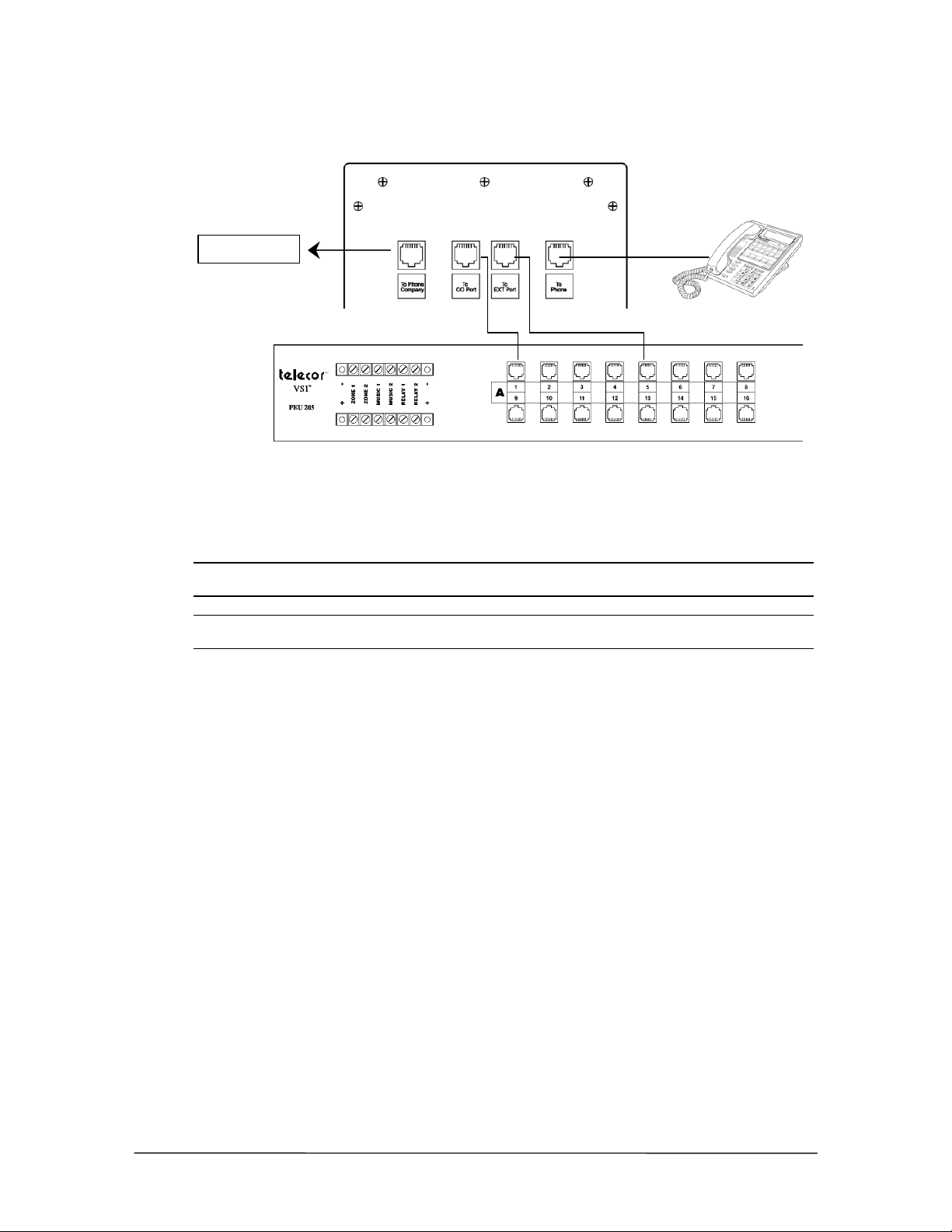
Telco Demarc
Final Cut-Over
Box Connection
Testing the Cut-Over Box
After all connections are made, test the Cut-Over Box by turning the switch on the bottom of the
Cut-Over Box to the Off position. The power indicator turns off. When the Cut-Over Box is off,
calls coming in on a CO line route directly to the corresponding extension.
Note Turning off the Cut-Over Box terminates existing phone calls on the CO lines connected to
it. Other lines are not affected.
Note If a power outage occurs, the Cut-Over Box automatically switches the connected CO
lines to their dedicated extensions.
Cut-Over Box Checklist
Mount the Cut-Over Box in the rack or to the wall.
Disconnect the RJ-11 cable from the first CO port on the PEU, and then connect it to Port
1 on the Cut-Over Box.
Connect the first CO port on the PEU to Port 2 on the Cut-Over Box.
Disconnect the RJ-11 cable from the first station port on the PEU, and then plug it into
Port 4 on the Cut-Over Box.
Connect the first station port on the PEU to Port 3 on the Cut-Over Box.
Connect additional CO ports to the other rows on the Cut-Over Box.
Turn off the Cut-Over Box to test it
34 Hardware
Page 49
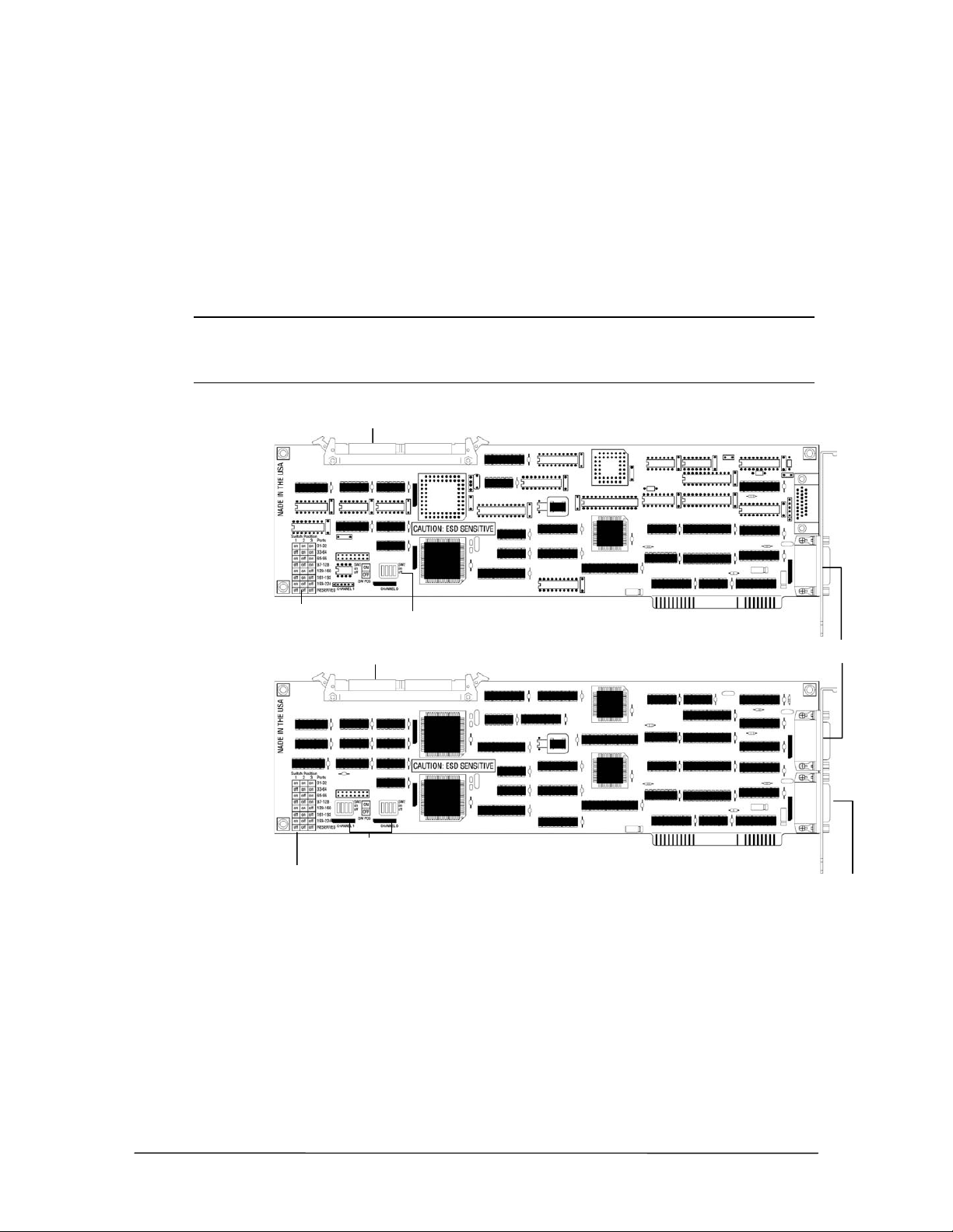
Installing a Host Adapter Card
r
r
Each TVS comes with one 32-port Host Adapter Card installed. Additional Host Adapter Cards
(either 32-port or 64-port models) are inserted into any unused ISA slot. Installing three 64-port
Host Adapter Cards expands the number of ports to 192. An Internal PCM Bus connector is attached
to the top of the Host Adapter Card, and is attached to any additional Host Adapter Cards already
installed in the TVS.
Each Host Adapter Card has switches that must be set to tell it which port numbers to support. A
switch settings table is printed on the Host Adapter Card for reference during installation.
Note Each Host Adapter Card has a unique Serial Number. The TVS uses the Serial Number of
the first Host Adapter Card ( ports 1-32) as the System ID Number. The System ID
Number is used to authenticate Activation Keys for that particular TVS. Replacing the Host
Adapter Card configured for ports 1-32 requires new Activation Keys for that TVS.
PCM Bus connecto
32-Port Host
Adapter Card
64-Port Host
Adapter Card
Switch settings
PCM Bus connecto
Switch settings
Switch block
Switch blocks
To install a Host Adapter Card in the TVS, complete the following steps:
1. Set the port switches on the Host Adapter Card to correspond with the PEU ports it is going to
support. Use the following table, or refer to the one printed on the Host Adapter Card. 64-port
Host Adapter Cards have two switch blocks to set.
Channel 0
Channel 1
Channel 0
VS1 Installation, Configuration & Operating Guide 35
Page 50
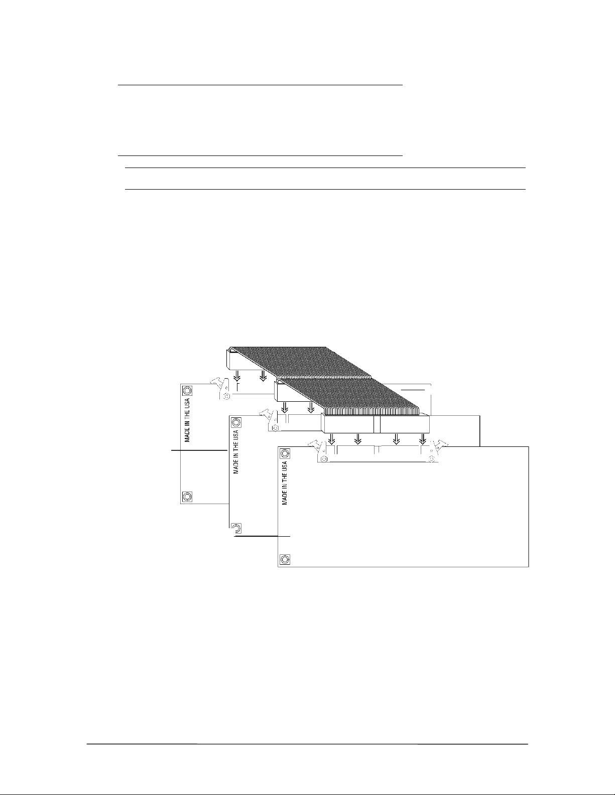
Set to Ports SW1 SW2 SW3 SW4
A
A
1-32 ON ON ON OFF
33-64 OFF ON ON OFF
65-96 ON OFF ON OFF
97-128 OFF OFF ON OFF
129-160 ON ON OFF OFF
161-192 OFF ON OFF OFF
Note Each Host Adapter Card must be configured for the range of ports it will support. Do not
configure two Host Adapter Cards for the same range of ports, or the system will not work.
2. Disconnect the CO lines from the PEU, and then turn off the system and unplug it. Disconnect
the Host Adapter Cable. Remove the TVS cover, and then lay the TVS on its side with the front
facing forward.
3. Locate an available ISA slot, and then remove its slot cover from the back of the TVS case.
4. Insert the Host Adapter Card into the selected ISA slot, and then secure it with the screw from
the slot cover.
5. Connect the new Host Adapter Card to the PCM Bus connector cable already attached to the
first Host Adapter Card and the Switch Card.
PCM Bus connector cable
Original Host
dapter Card
New Host
dapter Card
PCM Bus ribbon
connection
6. Replace the TVS cover, plug in the system, and then turn the power on. Reconnect the CO lines
to the PEU.
After installing a Host Adapter Card, you can connect additional PEUs to your Telecor VS1 phone
system. For more information, see “Installing Additional PEUs,” page 28.
36 Hardware
Page 51

Host Adapter Cards Checklist
Set the port switches on the Host Adapter Card.
Disconnect CO lines from the PEU, turn off the system, and then remove the TVS cover.
Locate an available ISA slot, and then remove its slot cover.
Install the Host Adapter Card in the TVS.
Connect the Host Adapter Card to the PCM Bus cable in the TVS.
Replace the TVS cover and reconnect the Host Adapter cable. Plug in and turn on the
system, and then reconnect CO lines to the PEU.
Connect additional PEUs to the TVS.
VS1 Installation, Configuration & Operating Guide 37
Page 52
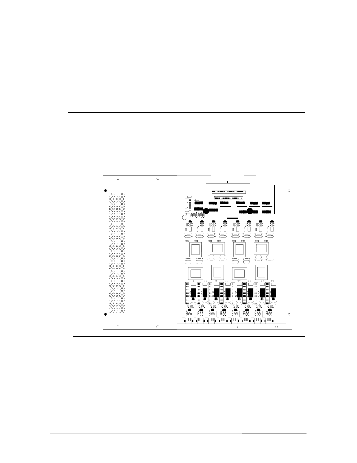
Installing the Caller ID Option Module
The Caller ID Option Module is installed inside a Port Expansion Unit Model 200 (PV-PEU-200) or
Port Expansion Unit Model 205 (PV-PEU-205), serial number 40,000 and above. The Caller ID
module is not used with the Port Expansion Unit Model 250 (PV-PEU-250) as it contains integrated
Caller ID circuitry on all 16 ports. If you want to set up Caller ID on CO lines connected to
additional PEUs, you must install additional Caller ID Option Modules in those PEUs.
To install the Caller ID Option Module inside a PEU, complete the following steps:
Warning! Before installing the Caller ID Option Module, first touch the metal case of the PEU to
discharge any static electricity. Static electricity can damage the Caller ID Option Module
and your system.
1. Disconnect the CO lines from the PEU, and then turn off the system. Unplug the PEU and
remove its cover.
2. Find the two male standoffs in the PEU. They are located on either side of the 50-pin connector.
Male Standoffs
in the PEU
Note Some PEUs have female standoffs instead of male standoffs. To install the Caller ID
Male standoffs
Option Module on a PEU with female standoffs, place the holes on the Module over the
female standoffs on the PEU. Use the two screws provided, and place them into the holes
to secure the Caller ID Option Module. If the Module is not properly installed, the holes do
not align and the screws do not fit.
Caller ID Option
Module Connector
3. Install the Caller ID Option Module with the component side facing down. Align the two holes
on the Module with the male standoffs.
4. Use the two nuts provided, and fasten them onto the standoffs to secure the Caller ID Option
Module. If the Module is not properly installed, the holes do not align, and the nuts do not fit on
the standoffs.
38 Hardware
Page 53
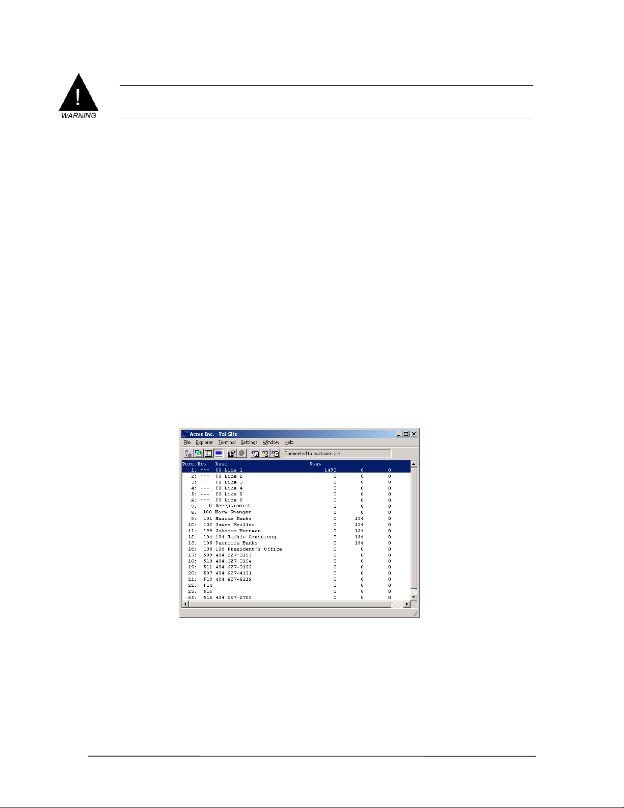
Warning! If the Caller ID Option Module is not installed correctly it will damage your equipment.
Improper installation voids the warranty on the Caller ID Option Module and on the PEU
into which it is installed.
5. Replace the cover on the PEU, and then plug it in.
6. Reconnect the CO lines.
See “Port Configurations” in the VS1 Editor section for activating Caller ID.
Verifying the Caller ID Option Module
When the Caller ID Module is properly installed and configured, Caller ID numbers are sent to
station option displays. If a CID Error on the station option display is received, the system could not
find the Caller ID Module board. If an N/A error on the station option display is received, the
system could not find the Caller ID service from the phone company. Contact the phone company to
ensure that Caller ID service has been activated.
To verify the Caller ID Option Module:
1. Using the Terminal window in the Tel-Site system management application, type ls at the
TVS Command prompt. This displays a list of all ports and their status.
2. Press the SPACEBAR to open the Polling window in the Line Status window. The first column
represents a device polled and responding correctly; the second column represents a device
polled with no response; the third column represents a device polled with an invalid response.
To restart the counters, type r.
3. If the Caller ID Module is working, the first CO Line port shows activity in the first column. If
there is activity in the second column, the Caller ID Module is not functioning properly.
The Polling
Window
Caller ID Option Module Checklist
Disconnect the CO lines from the PEU, and then unplug it.
Install the Caller ID Option Module in the PEU.
Confirm that Caller ID has been activated by the phone company.
Use the VS1 Editor configuration program to activate Caller ID.
Verify that Caller ID is working.
VS1 Installation, Configuration & Operating Guide 39
Page 54
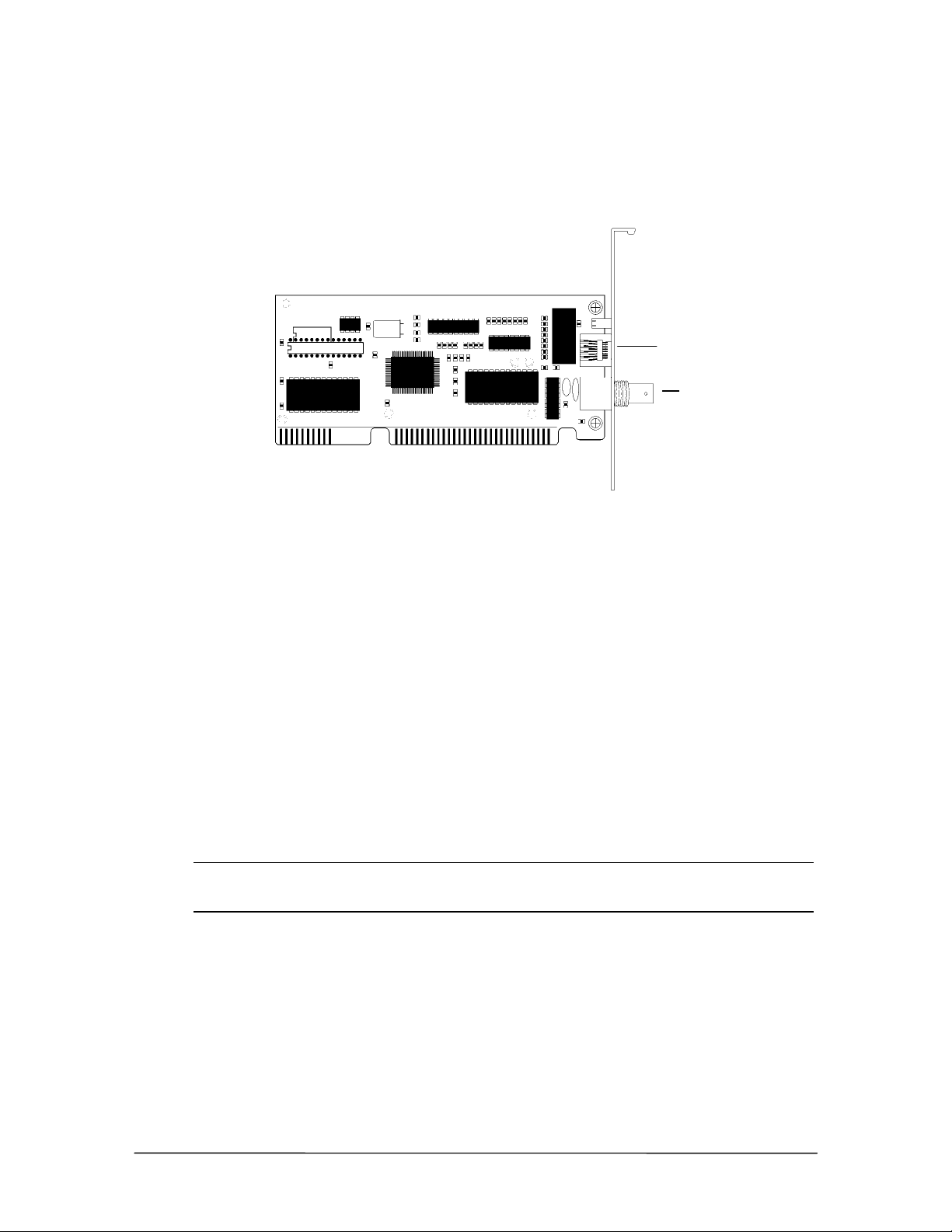
Installing a 10Base-T Network Interface Card
The 10Base-T Network Interface Card is inserted into any unused 16-bit ISA slot. It has a
preconfigured I/O address of 340 IRQ 11. An RJ-45 connector is provided on the 10Base-T
Network Interface Card for connection to the network.
10Base-T Connector
BCN Connector
(10Base-2)
10Base-T Network
Interface Card
To install a 10Base-T Network Interface Card in the TVS, complete the following steps:
1. Disconnect the CO lines from the PEU, and then turn off the system and unplug it. Remove the
TVS cover, and then lay the TVS on its side with the front facing forward.
2. Locate an available 16-bit ISA slot, and then remove its slot cover from the back of the TVS
case.
3. Insert the 10Base-T Network Interface Card into the selected ISA slot, and then secure it with
the screw from the slot cover.
4. Replace the TVS cover, and then connect the RJ-45 cable from the Network to the Connector
on the 10Base-T Network Interface Card.
5. Plug in the system, and then turn the power on. Reconnect the CO lines to the PEU.
Configuring the 10Base-T Network Interface Card
The TVS automatically detects the presence of the 10Base-T Network Interface Card. Complete the
following steps to connect to the network.
Note If your system uses switch card model 100 and a network card configured for use with
IRQ11, the TVS will not detect the 10Base-T Interface card. Call Telecor Technical
Support for assistance.
1. Using the VS1 Editor configuration program, select the System Configuration 2 pane.
2. Enter the following information in the Network group box:
UserName: Type a valid UserName on the network. The UserName must have a password to work
correctly. The UserNameis a case-sensitive box.
Password: Type a valid password on the server for the user described in the UserName box.
Password is a case-sensitive box.
40 Hardware
Page 55
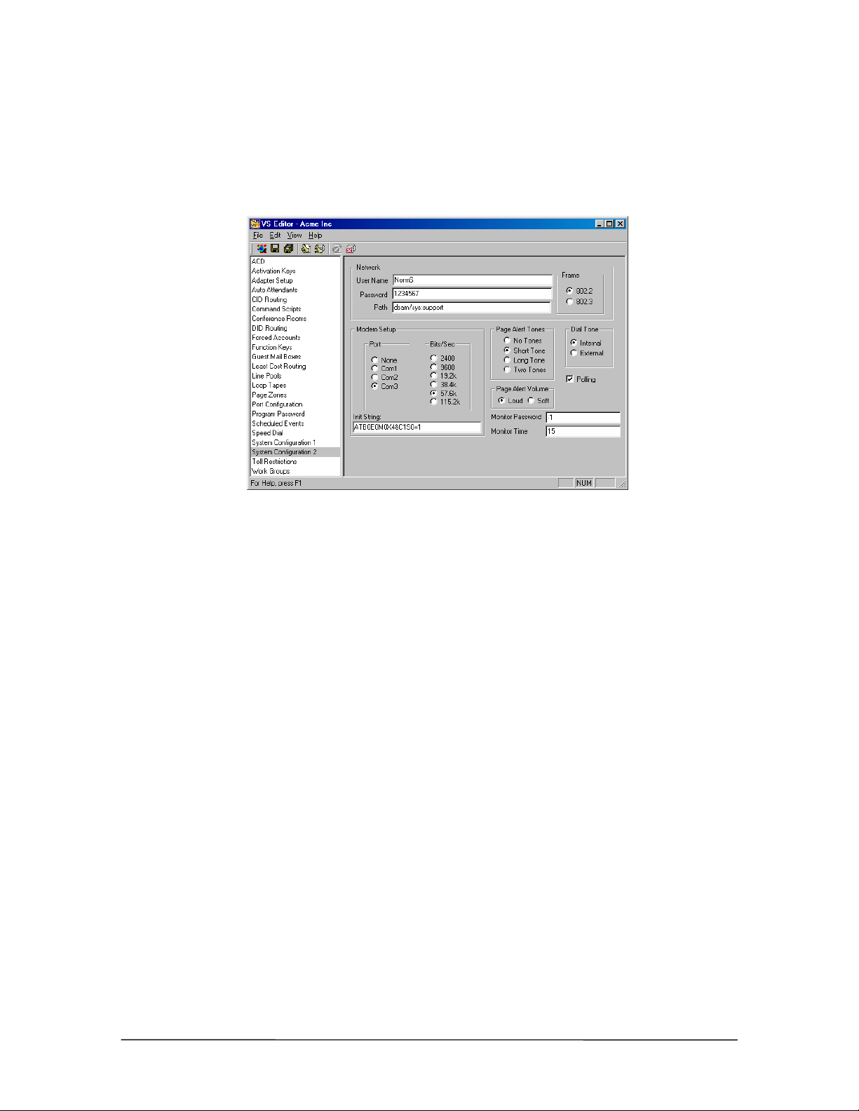
Path: Path is the server name, volume, and path that you want the SMDR information written to on
your server. For example, dsam/sys:support configures the network path to the support
directory on the sys volume of the DSAM server.
3. In the Frame group box, set the frame to match the frame type of the network server that you
are logging on to.
System
Configuration 2 pane
4. Click the Save button in the toolbar to save your changes
See “Station Message Detail Recording (SMDR)” in the Reference section to redirect SMDR files
through a network.
10Base-T Network Interface Card Checklist
Disconnect the CO lines from the PEU, turn off the system, and then remove the TVS
cover.
Locate an available 16-bit ISA slot, and then remove its slot cover.
Install the 10Base-T Network Interface Card in the TVS.
Replace the TVS cover, and then connect the RJ-45 cable from the Network to the
Connector on the 10Base-T Network Interface Card.
Plug in and turn on the system, and then reconnect the CO lines to the PEU.
Use the VS1 Editor configuration program to configure the 10Base-T Network Interface
Card.
See “Station Message Detail Recording (SMDR)” in the Reference section to redirect
SMDR files through a network.
VS1 Installation, Configuration & Operating Guide 41
Page 56
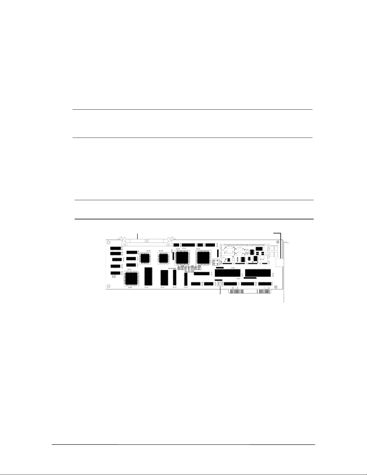
Installing a T1 Interface Card
r
The T1 Interface Card is installed inside the Telecor Voice Server (TVS) and supports 24 T1
channels. A maximum of two T1 Interface Cards can be installed in the TVS. The following table
shows the number of T1 channels and Analog CO lines that can be configured for each T1 card
installed in the TVS.
Number of T1
Cards
T1 channels
Maximum
# of PEUs
Maximum
Analog CO lines
Maximum
Total Ports
0 0 12 96 192
1 24 10 72 184
2 48 8 48 176
The T1 Interface Card is an ISA card and is inserted into any unused ISA slot. The internal bus
connector fits on top of the T1 Interface Card that attaches it to the other Telecor VS1 phone system
cards. The T1 Interface Card has a built-in channel service unit, and no additional Telecor VS1
phone system hardware is required. Switch settings for T1 Interface Cards are different from the
switch settings used for Host Adapter Cards. The first T1 Interface Card (T1 Card 0) must be
installed into the range of ports from 97 to 128. The second T1 Interface Card (T1 Card 1) must be
installed into the range of ports from 65 to 96.
Note If you already have a Host Adapter Card installed and a PEU is configured for Ports
96–128 or Ports 65–96, change the PEU port assignments before configuring the
T1 Interface Card.
PCM Bus Connecto
RJ48C Connection to Network
T1 Interface Card
Switch block
Ordering T1 Service
Before installing a T1 Interface Card, determine what type of service is required on-site, and then
order T1 service from the local phone company. When placing an order, provide the FCC ID
number from the label on the T1 Interface Card. You have the following T1 service options:
• DID (Direct Inward Dialing)—reports the number that was dialed by the calling party. A Service
Provider determines the number of digits in the number string and assign a block of numbers to a
DID hunt group. The smallest block is usually 100 numbers. These numbers can be used as direct
dials to extensions, Guest Mailboxes or Voice Mail for an extension.
• ANI (Automatic Number Identification)—reports the number of the calling party. This is
similar to Caller ID on an analog line. However, the only information provided is the number from
which the caller is calling. Name information is not sent by the Service Provider.
• DNIS (Dialed Number Identification Service)—reports the number that was dialed by the
calling party. A Service Provider determines the number of digits in the number string
42 Hardware
Page 57
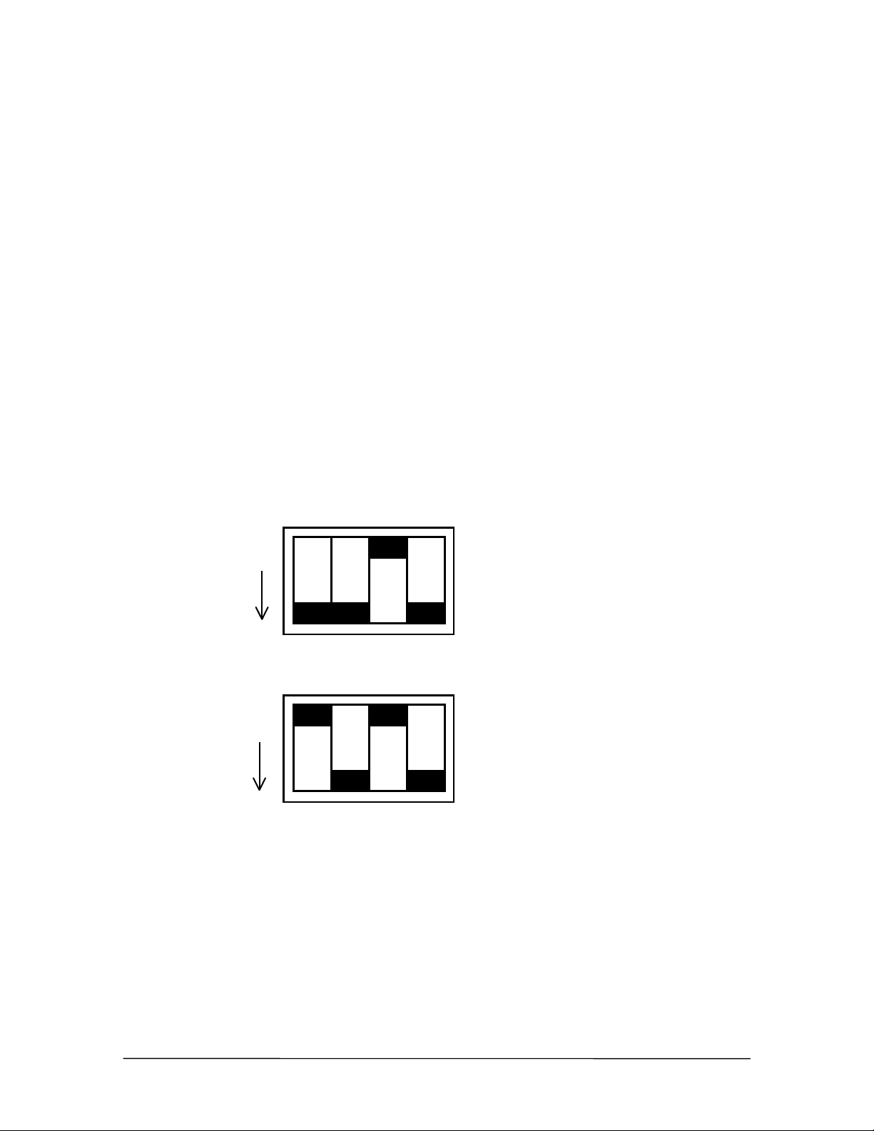
(minimum=1, maximum=10) and assigns numbers as you want. For example, you may want only
the last four digits of similar numbers in order to differentiate between them. DNIS is typically
only available on inbound 800 service.
Outbound lines may or may not have a phone number assigned. If a phone number is assigned by
the Service Provider, these lines can be used to receive incoming calls.
The T1 Interface Card receives DID or ANI information using MF (Multi-Frequency) or DTMF
(Dual Tone Multi-Frequency) tones. The T1 Interface Card automatically determines if MF or
DTMF is present on a call-by-call basis. Dial pulses are not generated or used by the T1 Interface
Card.
When ordering T1 service, request a framing mode of ESF (Extended Super Frame), but be aware
that many Service Providers supply only D4 framing. ESF provides troubleshooting capabilities that
are not available with D4. If ESF framing mode is available, request B8ZS (Bit Eight Zero
Suppression) line coding. If ESF is not available, AMI (Alternative Mark Inversion) line coding is
usually used.
Installing the T1 Interface Card
To install the T1 Interface Card, complete the following steps:
1. Verify that the switches on the T1 Interface Card are set to the correct positions.
• Switches on the first T1 Interface Card should be set for ports 97–128.
OFF
Switch settings for
T1 Card 0
Ports 97-128
SW1
• Switches on the second T1 Interface Card should be set for ports 65–96.
OFF
Switch settings for
T1 Card 1
Ports 65-96
SW1
2. Disconnect the CO lines from the PEU and the Host Adapter cables connecting the TVS to the
PEU. Turn off the TVS, unplug it, and then remove the cover.
3. Locate an available ISA slot, and then unscrew and remove its slot cover from the back of the
TVS case.
4. Insert the T1 Interface Card in the selected ISA slot. Push firmly to set the T1 Interface Card
into the slot and to ensure proper connection, and then secure it with the screw from the slot
cover.
5. Connect the PCM bus cable to the connector at the top of the card.
VS1 Installation, Configuration & Operating Guide 43
Page 58
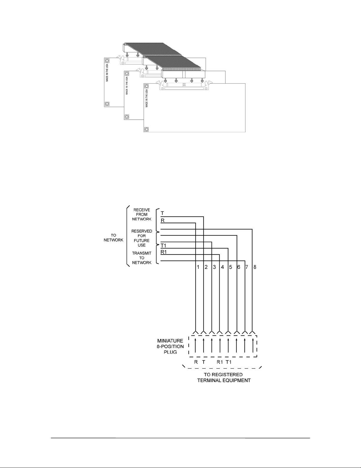
Connecting the T1
Interface Card to the
ribbon bus cable
6. Replace the TVS cover, and then reconnect the Host Adapter Cables. Turn the system on, and
then reconnect the CO lines.
Cable Installation
After installing the T1 Interface Card, make the cable connection from the Telco Demarc
(T1 repeater) point to the RJ48C jack on the end of the T1 Interface Card. Telecor provides a cable
with connectors. If a longer cable is required, it must be constructed from Category 5 twisted pair
wiring connected to pairs 1 and 2 with an RJ48C connector at each end.
T1 cable wiring
diagram
See “T1 Interface Card Configuration” in the Reference section for setting up the T1 Interface
Card.
44 Hardware
Page 59

Installing the CTIM
The Computer Telephony Interface Module (CTIM) provides a digital interface to the VS1 phone
system for the Telecor Attendant and Connect applications. The CTIM is an external device with a
headset jack intended for use only with the VS1 phone system. To install the CTIM, complete the
following steps:
1. Close all applications, and then turn off the computer.
2. Connect the female end of a 9-pin serial port cable to an available 9-pin male COM port on the
computer you want to use with the CTIM.
Note If you computer has an available 25-pin COM port, obtain a 25-to-9-pin serial port adapter
and connect that to the 25-pin COM port on the computer.
3. Connect the male end of the 9-pin serial cable to the DB9 female connector on the CTIM.
Note If you are installing the CTIM for use with Telecor Attendant, the DB9 connector on the
CTIM is not used.
4. Connect a four-conductor RJ-11 patch cord from the wall jack to the RJ-11 jack labeled “Line”
on the CTIM.
5. Connect a headset to the RJ-22 jack labeled “Headset” on the CTIM.
6. Set the Ear, Mic and Sidetone volume control jumper settings on the CTIM for the headset or
handset you use. The table below shows the volume settings for Ear and Mic.
7. Set the Sidetone to Hi or Lo, according to user preference. The Sidetone is set to Low by
default.
8. The CTIM installation is complete. Turn the computer on.
CTIM
Computer Telephony Interface Module
Volume E2/M2 E1/M1 E0/M0
1(LO) off off off
2offoffon
3 off on off
4 off on on
5onoffoff
6onoffon
Volume settings for
Ear and Mic
7 ononoff
8 (HI) on on on
CTIM Checklist
Turn off the computer
Locate an available external 9-pin male COM port on the computer, and connect the
female end of a serial cable to it.
Connect the male end of the serial cable to the female connector on the CTIM.
Connect an RJ-11 cord from the wall jack to the “Line” jack on the CTIM. Connect a
headset to the RJ-22 “Headset” jack on the CTIM.
Set the Ear, Mic, and Sidetone volume control jumper settings on the CTIM.
Turn the computer on.
VS1 Installation, Configuration & Operating Guide 45
Page 60

Installing the PC Option Module (PCOM)
The PC Option Module (PCOM) provides an externally connected serial interface to a computer for
data sent by the Telecor Voice Server (TVS). The PCOM is used with the Telecor Connect CTI
client application. By installing a PCOM, Connect users can use their computer screen for call
processing and keep the phone on their desk. Keeping a phone on the desk also allows calls to be
received when the computer is turned off. To install the PCOM, complete the following steps.
1. Close all applications, and then turn off the computer. Locate an available 9-pin or
25-pin serial port on the back of the computer.
2. If there is not an available serial port on the computer, you need to install one.
3. Connect the 9-pin DB9 female connector of the PCOM cable adapter to the 9-pin DB9 male
connector of the computer.
4. Connect the phone line from the station jack to one of the RJ-11 jacks on the PCOM.
5. Connect the phone to the other RJ-11 jack of the PCOM. PCOM installation is complete. Turn
the computer on.
PCOM Checklist
Turn off the computer
Locate an available external 9-pin or 25-pin serial port or install one.
Connect the PCOM to the computer using the 9-pin DB9F connectors.
Connect the phone line and phone to the RJ-11 jacks on the PCOM.
Turn the computer on.
46 Hardware
Page 61

CREATING AN EMERGENCY BOOT FLOPPY
An Emergency Boot Floppy must be created to restart the TVS in case of system failure. The disk is
created on-site with a monitor and keyboard connected to the TVS. To create an Emergency Boot
Floppy you need one high-density, write-enabled disk. The procedure takes approximately 15
minutes and must occur during downtime. Complete the following steps:
1. If the server is running with the Command prompt displayed (Command - >), type stop or exit
and then press
or
2. If the server is not running and the DOS prompt is displayed (C:\>), press the RESET button
the server.
• The server restarts.
3. When the VS1 Options menu appears, press 2 to select the VS1 Configuration option.
4. On the VS1 Configuration menu, press 4 to select the Create an Emergency Boot Floppy
option.
5. Insert the high-density, write-enabled disk into Drive A of the TVS, and then press ENTER.
• The TVS formats the disk, then copies the necessary files to it. In addition to copying the
files needed to boot the TVS, a copy of the system configurations is saved to the disk. This
procedure takes several minutes to complete.
ENTER on the keyboard.
6. Remove the disk when prompted. Label the disk and store it in a safe place.
7. Press any key when the process is complete.
Note Voice Mail and SMDR data cannot be saved while the system is operating from an
Emergency Boot Floppy.
8. When the VS1 Configuration menu (or TVS Startup menu) appears, press 0 to restart the
server.
VS1 Installation, Configuration & Operating Guide 47
Page 62

Tel-Site
Page 63

OVERVIEW OF TEL-SITE
Tel-Site provides remote system access (RSA) to the VS1 phone system. Tel-Site is used for the
following:
• Connecting with the customer TVS to upload configuration changes
• Downloading and uploading customer TVS files
• Performing file maintenance
• Diagnosing problems
• Setting the date and time on the customer TVS
• Setting up T1 parameters (for systems with a T1 card)
This section first introduces the windows that Tel-Site uses and how to set up a new customer site. It
then documents the different connection methods available for connecting to a site. Finally, it
provides basic Tel-Site operating instructions, which cover the following:
1. Connecting to a site.
2. Downloading any changed files from a site.
3. Accessing the VS1 Editor to change site configurations.
4. Uploading files to a site.
5. Reloading Configuration changes.
The Tel-Site application is available for download from the VS1 Dealer Page of the Telecor Web
Site (www.telecor.com). Please visit the page for details on obtaining licensing information and
installing the application.
The Tel-Site application is a Windows®-based program that operates on Microsoft® Windows® 98,
Windows
To work properly, the modems used for Tel-Site should be 14.4 kilobits per second (Kbps) or faster.
®
2000, and Windows® XP operating systems.
VS1 Installation, Configuration & Operating Guide 51
Page 64
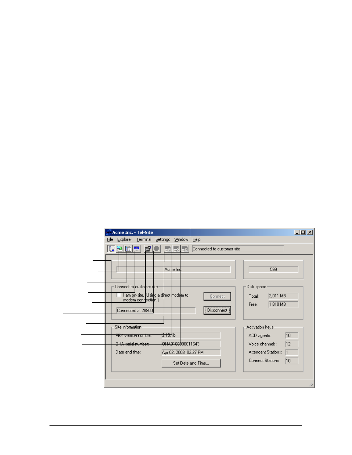
Tel-Site Windows
Tel-Site includes the following windows:
Connection Window – to connect or disconnect from a site
Configuration Window – to configure a customer site
Explorer Window – to perform discretionary file maintenance
Terminal Window – to provide a snapshot of the real-time dynamics of a site for troubleshooting
purposes.
The following pages include brief descriptions of each window. For further information, see the TelSite Help file.
The Connection Window
The Connection window for Tel-Site appears when the application is first started. After setting up a
customer site profile (see “Setting up a New Site,” page 56), the Connection window is where you
can connect or disconnect from a site. In the Connect to customer site group box there is a
Connect and Disconnect command button.
Once connected, information about the Telecor Voice Server at the site is displayed. This includes
site information, such as the version number of the Voice Server at the site, information about free
space on the hard disk, and activation keys. You can also change the date and time of the Voice
Server.
Menu bar
Connection window
Configuration window
Explorer window
Terminal window
Window Properties
Stop
Capture window
Time Capture
Clear Capture
Connection window
Help menu
52 Tel-Site System Management Application
Page 65
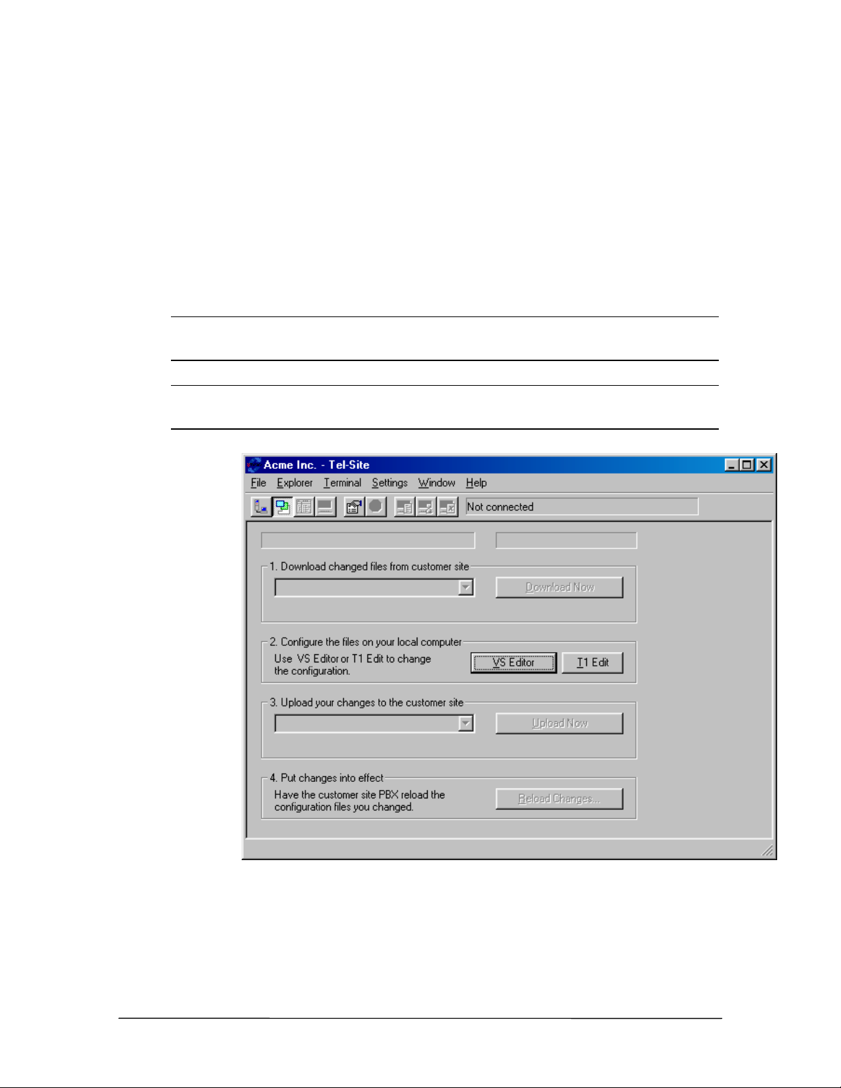
The Configuration Window
The Configuration window is used to perform remote configuration of a customer site. When
connected to a customer site and the Configuration window is opened, Tel-Site scans and displays
any TVS files that have changed since the last remote activity. It can then download any updated
files so that your local computer matches the latest customer site configuration. The VS1 Editor
configuration program is then used to configure the files on your local computer. Once configured,
the changes are uploaded to the customer TVS and put into effect.
The Configuration window is also used to configure a T1 Interface Card by clicking T1 Edit. See
“T1 Interface Card Parameter Setup Using Tel-Site” in the Reference section for more
information.
Note Typically, the Connection window is used to connect to a customer site, but the
Configuration window can be opened prior to connecting to a site to examine the last
downloaded configuration.
Note The first time you open the Configuration window after upgrading the TVS software, a
dialog box opens indicating an upgrade has occurred. You must download all of the
Configuration files so they correspond with the latest VS1 software version.
Configuration
window
VS1 Installation, Configuration & Operating Guide 53
Page 66
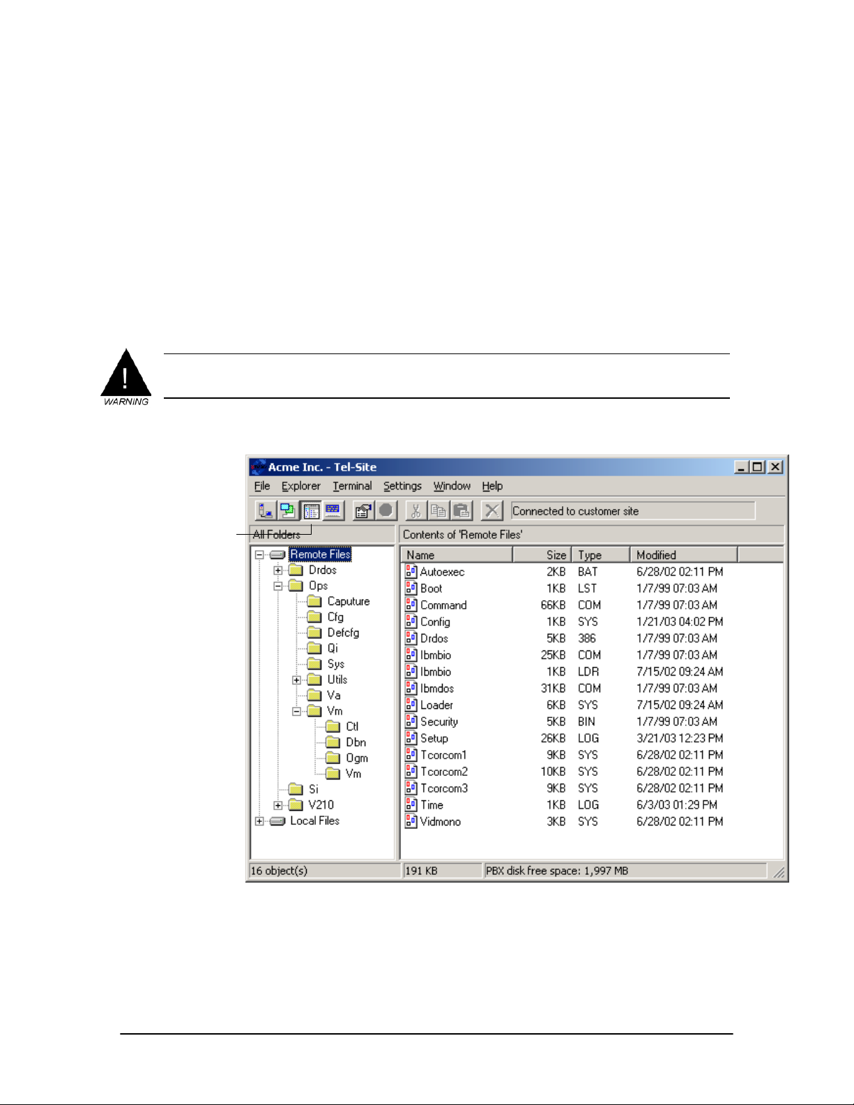
The Explorer Window
The Explorer window is designed to perform discretionary file maintenance. It can be used to
upload and download files that are not automatically handled by the Configuration window.
The Tel-Site application keeps track of all changes made to the customer TVS files within the
Explorer window. The Explorer window does not keep track of changes made in the Connection
window or the Terminal window. The status panel at the bottom of the Explorer window shows
the amount of free disk space available on the TVS.
`The Explorer window design is similar to the Windows® Explorer® and many of the features are
the same. However, you cannot place or delete files in the Recycle Bin. In addition, the Tel-Site
application considers certain folders and files on the customer TVS as critical to operation. These
critical files and folders cannot be deleted.
WARNING! Because you can upload any file to the TVS, there is a risk of uploading a damaged or
incompatible file if you do not have a complete knowledge of the files required for TVS
operation. Uploading a damaged or incompatible file can be as bad as deleting the file.
Explorer window
toolbar button
Explorer window
54 Tel-Site System Management Application
Page 67
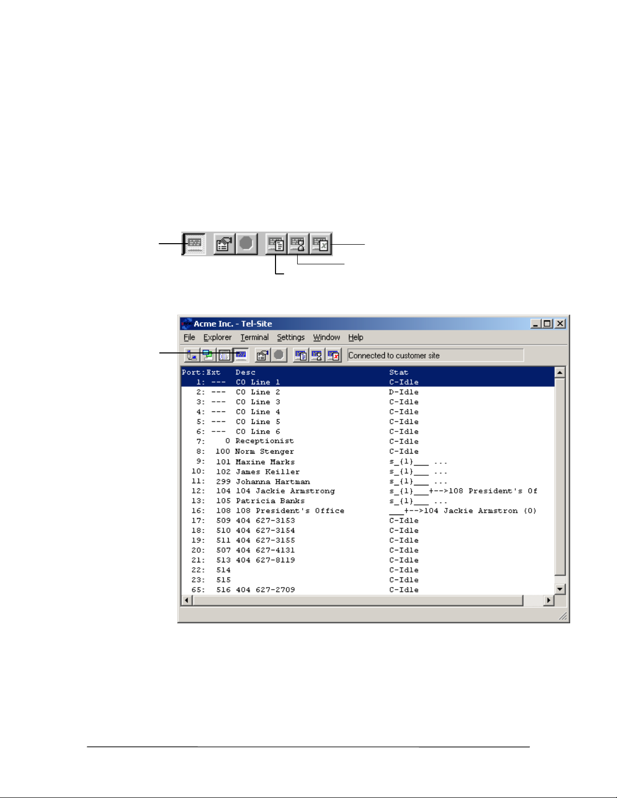
The Terminal Window
The Terminal window simulates the monitor display of the TVS for troubleshooting a site. It
provides snapshots of the real-time dynamics of a remote phone system. With the Terminal window
you can capture and create a text file of important configuration information from a remote site. For
example, you can capture a T1 setup and create a text file for later reference (if the file does not
exist, it is created automatically).
The toolbar has four buttons used for the Terminal window: Terminal Window, Capture
Window, Timed Capture, and Clear Capture buttons. The latter three buttons appear dimmed, or
unavailable, until the Terminal window is activated.
Terminal window
Terminal window
toolbar button
Clear Capture
Timed Capture
Capture window
Terminal window
(displaying “line
status”)
VS1 Installation, Configuration & Operating Guide 55
Page 68
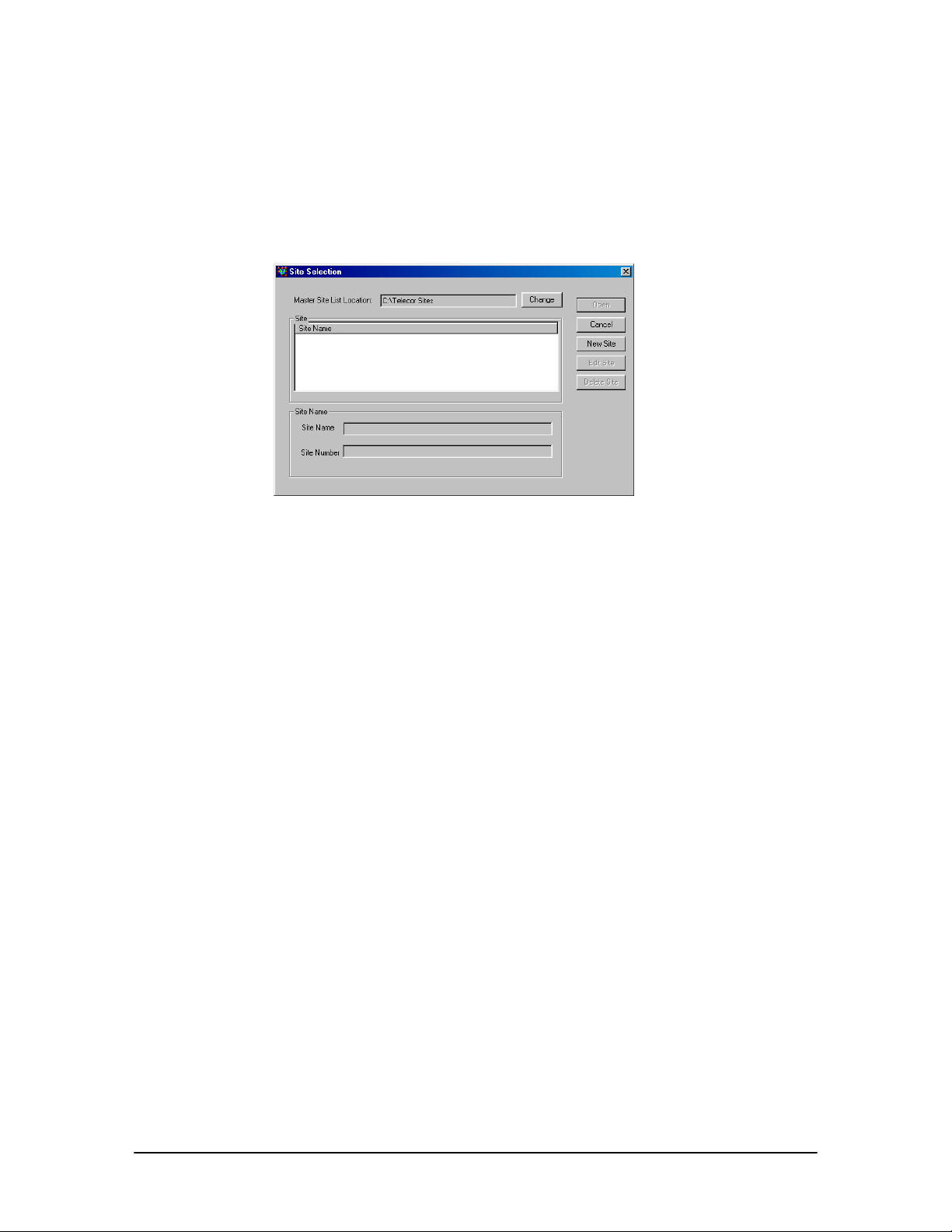
Setting up a New Site
To set up a new customer site, complete the following steps:
1. From the File menu, click Site Selection.
• The Site Selection window appears.
Site Selection
window
2. By default, Site Selection will store customer sites in the C:\Telecor Sites directory, as
displayed in the Master Site List Location box. To change the Master Site List Location, click
Change and navigate to the directory where sites will be stored.
3. Click New Site.
• The New Customer Site dialog box appears.
4. In the Customer Site Name text box, enter a name or description for the customer site.
5. Click Next.
6. Leave the Phone Number text box blank. This box will be filled in later when you connect to
the TVS for the first time.
7. Leave the RSA password text box blank. If the TVS is later assigned a Remote System Access
password, then you will be instructed to fill this box in. See “Remote System Access Password”
on page 78 for more information.
8. Uncheck the Modem shares a CO line check box.
9. Click Finish.
10. The Site Selection window appears with the new site listed under the Site Name column.
Notes:
• Site information can be changed by clicking Edit Site in the Site Selection window.
• The New Customer Site dialog box is available only when you are not connected to a
customer site.
56 Tel-Site System Management Application
Page 69
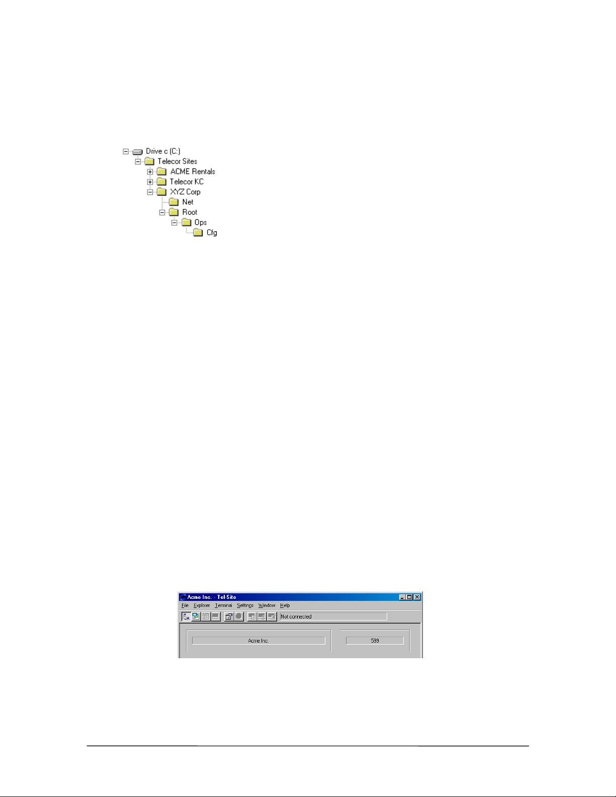
How Tel-Site Organizes Site Information
Tel-Site makes it easy for you to organize multiple customer sites within a single folder on your
local computer. By default, this folder is C:\Telecor Sites, but you can use a different folder if you
like. The illustration shows three customer sites arranged this way.
The XYZ Corp folder also shows the folders that map to the customer TVS. The Net folder
represents the network drive on the TVS, if present. The Root folder represents the TVS root folder,
and the Ops and Cfg folders map directly to their counterparts on the TVS.
When you set up a new customer site, you should choose a descriptive name for the site. This name
serves both as the site name and the folder name, such as XYZ Corp in the illustration. (If you
choose to keep customer sites on a drive that does not support long file names, you will need to use
a short name for the customer site. You can later change the site name to something more
descriptive if you like.)
Tel-Site does not require that the customer site name and the folder name remain the same. You can
change the site name, and you can rename or even move the site folder. After renaming or moving
the folder, you must open the site in its new location before you can connect to it.
Opening a Site
To open a site, complete the following steps:
1. From the File menu, click Site Selection.
• The Site Selection window appears.
2. Select a site from the Site Name column.
3. Click Open.
• The site opens, with its name displayed in the Connection window.
Site name displayed
in Connection
window
VS1 Installation, Configuration & Operating Guide 57
Page 70

CONNECTION METHODS
Tel-Site offers various methods for connecting to a TVS. One method is available for connecting to
a site locally (on-site) and three methods are available for connecting to a site remotely (off-site).
• Tel-Site Modem to TVS Modem through two PEU ports (on-site access)
• TVS Modem as an Extension (off-site access)
• Dedicated CO Line to TVS Modem (off-site access)
• TVS Modem Shares a CO Line (off-site access)
Note The TVS is configured by default to support an on-site connection. This allows for the
initial connection to the server in order to configure it for one of the three remote methods.
Tel-Site Modem to TVS Modem through two PEU ports (onsite)
The method for the on-site connection is a modem-to-modem connection through two Telecor Port
Expansion Unit (PEU) extension ports.
TVS Configuration
If connecting to the TVS for the first time, the TVS Configuration steps do not need to be followed,
as this configuration is enabled by default. Refer to these steps only if required to revert back to an
on-site connection. The on-site configuration tells the modem when to answer an incoming call and
ensures port 16 is defined as a Modem/Fax Port with extension 599.
1. With the site open, through Tel-Site, click the Configuration window button in the toolbar.
2. Click the VS1 Editor button.
• The VS1 Editor configuration program opens.
3. In the Tree Control display, click System Configuration 2.
4. In the Init String: text box, check that the end of the modem initialization string reads S0=1.
(S0=1 sets the modem to answer on the first ring.) By default, this setting is already in place.
58 Tel-Site System Management Application
Page 71
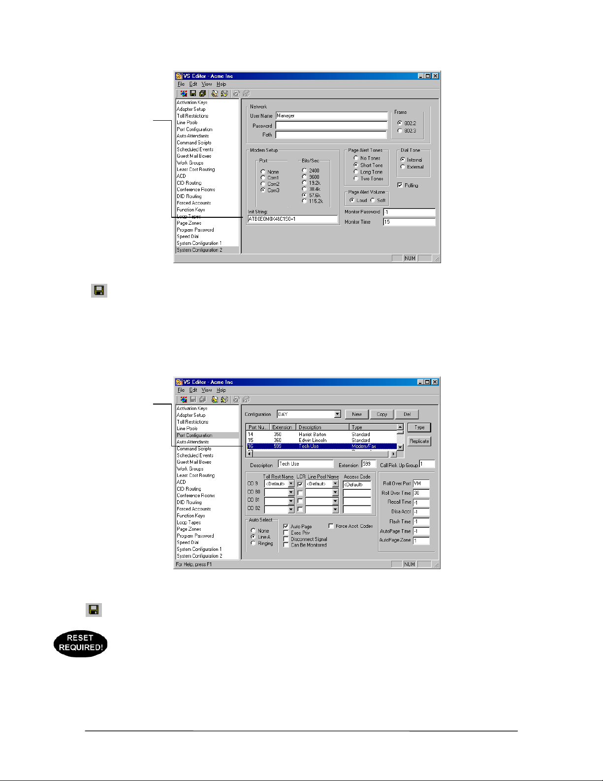
Modem
initialization string
Modem initialization
string for Tel-Site
Modem to TVS
Modem through two
PEU Extension Ports
connection
5. Click the Save button in the toolbar.
6. In the Tree Control display, click Port Configurations.
7. In each configuration, make sure that the extension port connected to the TVS modem is
configured as a Modem/Fax port with the extension 599 (the extension number 599 is reserved
for a Modem/Fax port). By default, extension port 16 is configured in this manner.
Modem/Fax port
Modem/Fax Port
Configuration
8. Click the Save button in the toolbar.
9. If steps 4 or 7 had to be changed from the default settings, use your current connection method
to upload the new settings to the customer TVS and reload the changes. See “Tel-Site Basic
Operation” on page 76.
VS1 Installation, Configuration & Operating Guide 59
Page 72
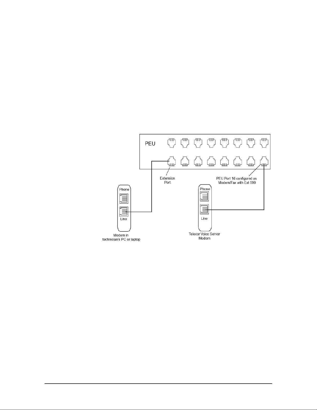
Hardware Setup
Prior to making the necessary hardware changes, ensure the TVS is configured to support the TelSite Modem to TVS Modem through two PEU Ports connection (see page page 58).
The diagram shows an on-site modem-to-modem connection through two PEU ports. A standard
telephone cord from the TVS modem is run to PEU Port 16, which is configured by default as a
Modem/Fax port with the extension number 599. Another telephone cord is run from the Tel-Site
laptop or PC to an unused extension port on the PEU.
Alternatively, the telephone cord from the Tel-Site computer does not need to be directly connected
to the PEU. It can be plugged into the data port of a Telecor DP200 Display Phone, or into a wall
jack of a station extension. The only requirement is that the cord is connected to an extension
somewhere on the system.
Tel-Site Modem to
TVS Modem through
Two PEU Extension
Ports (on-site
access)
60 Tel-Site System Management Application
Page 73
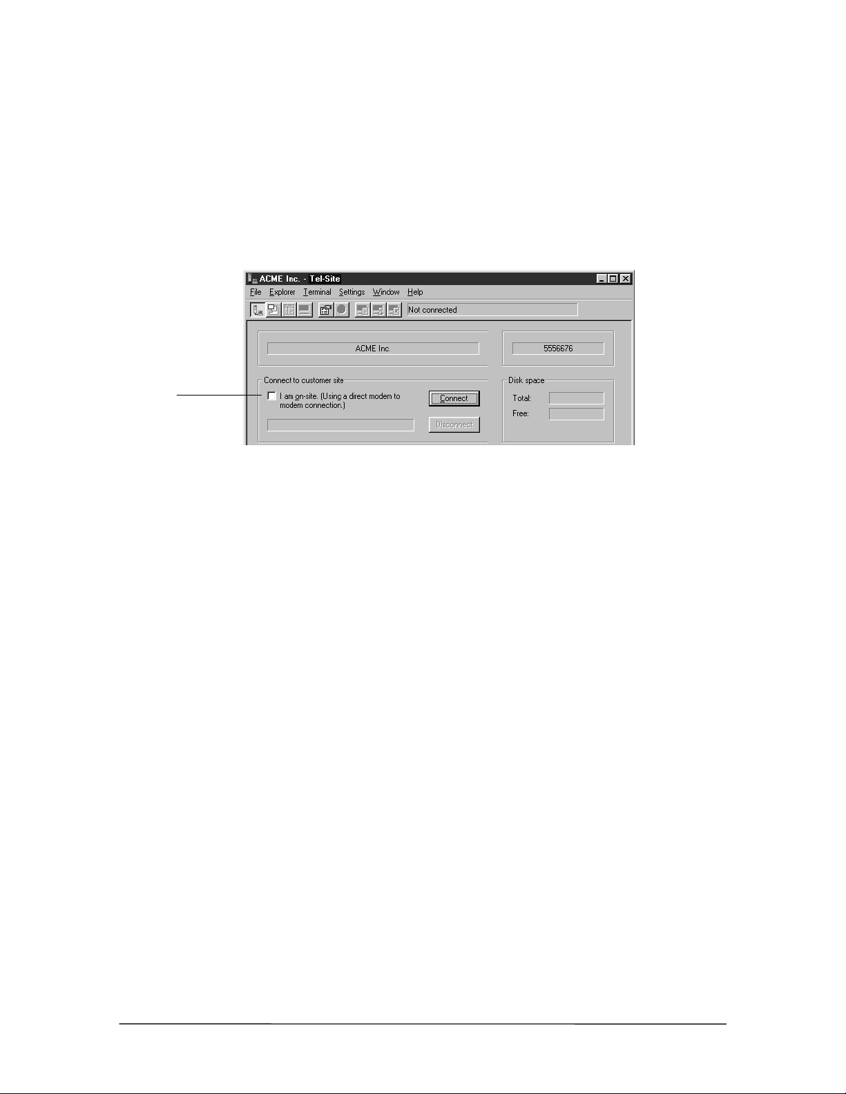
Tel-Site Setup
The connection between Tel-Site and the PEU extension port is made in much the same way as an
internal call, only a modem is answering instead of a station user. The Tel-Site application needs to
know what extension is going to answer the call.
1. In the Connection window, ensure the I am on-site. (Using a direct modem to modem
connection.) check box is cleared. Although you are on-site, the connection is made through an
extension port on the PEU, not directly to the modem in the TVS.
Ensure this box is
cleared
Connection window
2. From the File menu, click Site Selection.
• The Site Selection window appears.
3. Select the site from the Site Name column.
4. Click Edit Site.
• The Connection dialog box appears.
5. If an RSA password is required to enable the Tel-Site modem to communicate with the TVS,
enter it in the RSA password text box. See “Remote System Access (RSA) Password” on page
78 for more information. If connecting for the first time, leave this text box blank
6. In the Phone number text box, enter 599. Extension 599 is the default extension number of
Port 16, which is connected to the TVS modem.
7. Ensure the check box The modem shares a CO line is cleared.
VS1 Installation, Configuration & Operating Guide 61
Page 74
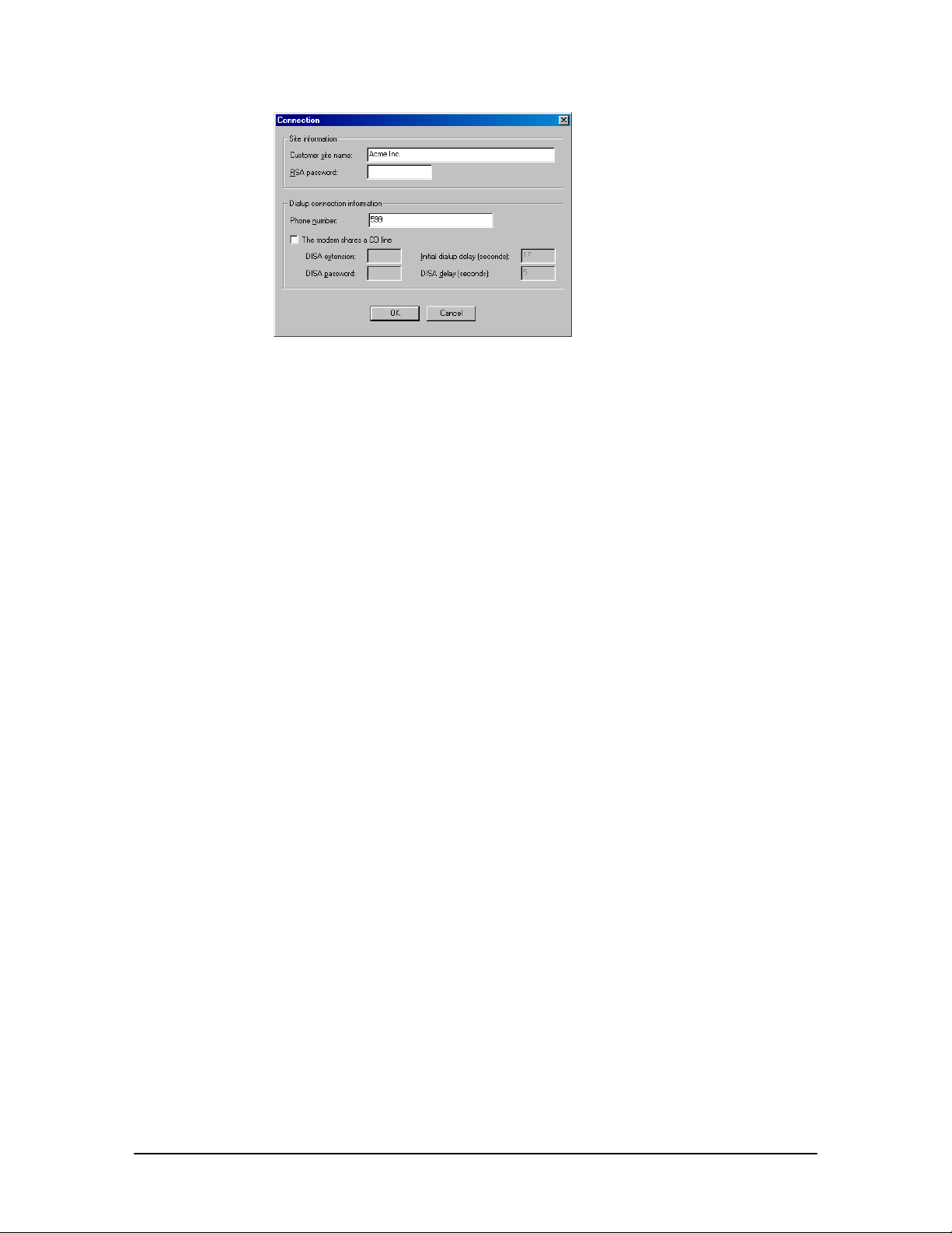
Setup in Connection
dialog box for TelSite Modem to TVS
Modem through two
PEU Extension Ports
connection
8. Click OK to return to the Site Selection window.
9. Click OK to return to the Connection window.
10. See “Tel-Site Basic Operation” on page 76 to:
• Connect to a site
• Download files from a site
• Change site configurations
• Assign an RSA (Remote System Access) password
• Upload files to a site
• Reload configuration changes
Tel-Site Modem to TVS Modem through Two PEU Extension Ports Connection Checklist
In the System Configuration 2 pane of the VS1 Editor program, set the modem to
answer on the first ring.
In each configuration, make sure that PEU Port 16 is configured as a Modem/Fax port
with the extension 599.
Using your current connection method, upload the new configuration settings (only if
changed from default) to the customer TVS and reload the changes.
Connect a standard telephone cord between the line jack of the TVS modem and PEU
port 16.
In the Tel-Site Connection window, verify that the I am on-site (Using a direct modem
to modem connection.) check box is not selected.
In the Connection dialog box of the Site Selection window, enter an RSA password if
required.
In the Phone Number text box, enter 599. Ensure The modem shares a CO line check
box is cleared.
62 Tel-Site System Management Application
Page 75
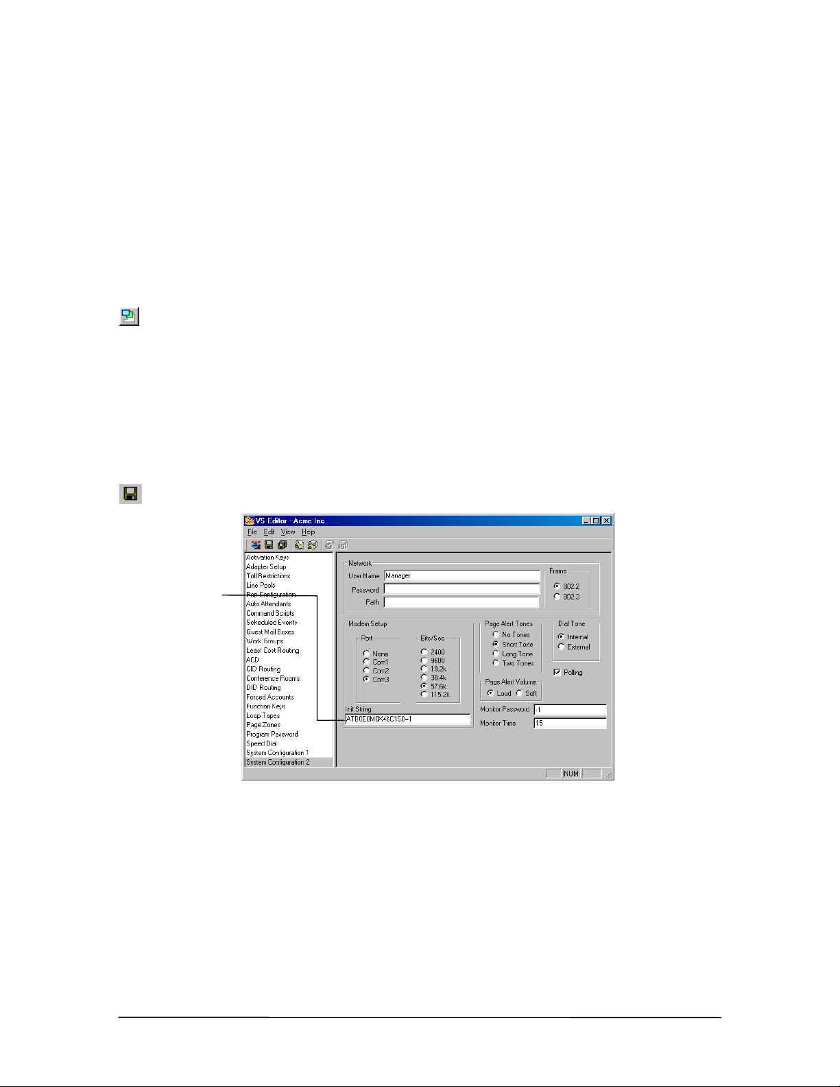
TVS Modem as an Extension Connection (off-site access)
The setup for this method is similar to the on-site modem to modem connection through two PEU
extension ports. The difference is that Tel-Site is calling in from a remote site and transferred (either
automatically by an Auto Attendant or manually by a receptionist) to the PEU extension port
connected to the TVS modem.
TVS Configuration
For a TVS Modem as an Extension Connection, the configuration tells the modem when to answer
an incoming call and ensures port 16 is defined as a Modem/Fax Port with extension 599.
1. With the site open through Tel-Site, click the Configuration window button in the toolbar.
2. Click the VS1 Editor button.
• The VS1 Editor configuration program opens.
3. In the Tree Control display, click System Configuration 2.
4. In the Init String: text box, check that the end of the modem initialization string reads S0=1.
(S0=1 sets the modem to answer on the first ring.) By default, this setting is already in place.
5. Click the Save button in the toolbar.
Modem
initialization string
Modem initialization
string for TVS
Modem as an
Extension
connection
6. In the Tree Control display, click Port Configurations.
7. In each configuration, make sure that the extension port connected to the TVS modem is
configured as a Modem/Fax port with the extension 599 (the extension number 599 is reserved
for a Modem/Fax port). By default, extension port 16 is configured in this manner.
VS1 Installation, Configuration & Operating Guide 63
Page 76
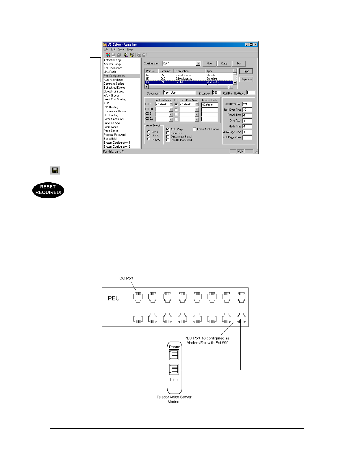
Modem/Fax port
Modem/Fax Port
Configuration
8. Click the Save button in the toolbar.
9. If step 4 or step 7 had to be changed from the default settings, use your current connection
method (such as the default on-site connection) to upload the new settings to the customer TVS
and reload the changes. See “Tel-Site Basic Operation” on page 76.
Hardware Setup
Prior to making the necessary hardware changes, ensure the TVS is configured to support the TVS
Modem as an Extension connection (see page 63).
The diagram below shows the hardware setup for a modem as an extension connection. A standard
telephone cord is run from the line jack of the TVS modem to PEU port 16 configured as a
Modem/Fax Port with the extension 599.
TVS Modem as an
Extension (off-site
access)
64 Tel-Site System Management Application
Page 77
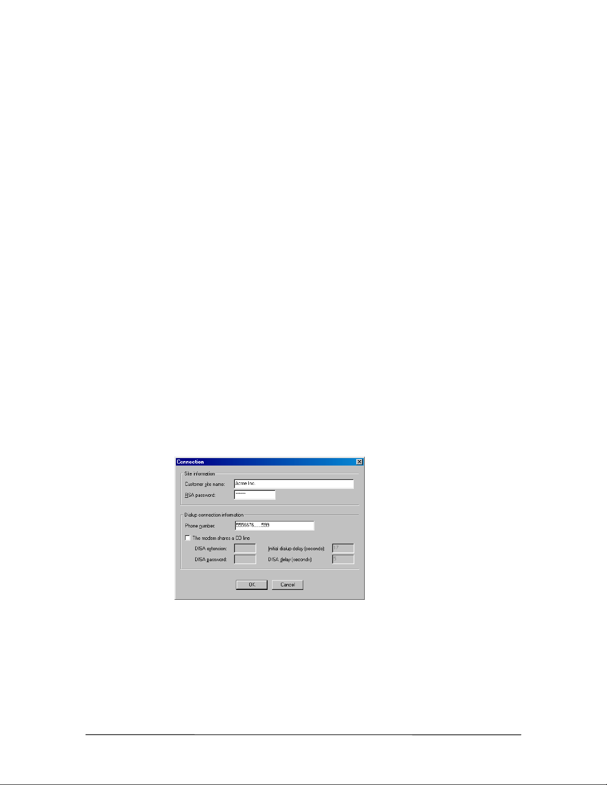
Tel-Site Setup
For a TVS Modem as an Extension Connection, Tel-Site must be set up so that it can dial the
customer site phone number. If answered by an Auto Attendant, Tel-Site must automatically dial the
extension number 599. If answered by a receptionist, the call must be manually transferred to
extension number 599.
1. From the File menu, click Site Selection.
• The Site Selection window appears.
2. Select the site from the Site Name column.
3. Click Edit Site.
• The Connection dialog box appears.
4. If an RSA password is required to enable the Tel-Site modem to communicate with the TVS,
enter it in the RSA password text box. See “Remote System Access (RSA) Password” on page
78 for more information.
5. In the Phone number text box, enter the customer site phone number to dial. If the Tel-Site call
is to be answered by an Auto Attendant, enter five or six commas after the phone number and
then the extension number 599. Each comma is used as a 1-second delay in the dialing process
to give the Auto Attendant time to answer before it receives the digits 599. The number of
commas used may vary depending on how long it takes for the Auto Attendant to answer.
If the Tel-Site call is to be answered by a receptionist, you must contact the receptionist
beforehand and let her know that a modem call will be made. Inform her that when she answers
the modem call to please transfer it to extension 599.
6. In the Dialup connection information group box, ensure The modem shares a CO line check
box is cleared.
Connection dialog
box for TVS Modem
as an Extension
connection with Auto
Attendant answering
7. Click OK to return to the Site Selection window.
8. Click OK to return to the Connection window.
9. See “Tel-Site Basic Operation” on page 76 to:
• Connect to a site
VS1 Installation, Configuration & Operating Guide 65
Page 78

• Download files from a site
• Change site configurations
• Assign an RSA (Remote System Access) password
• Upload files to a site
• Reload configuration changes
TVS Modem as an Extension Connection Checklist
In the System Configuration 2 pane of the VS1 Editor program, set the modem to
answer on the first ring.
In each configuration, make sure that PEU Port 16 is configured as a Modem/Fax port
with the extension 599.
Using your current connection method, upload the new configuration settings (only if
changed from default) to the customer TVS and reload the changes.
Connect a standard telephone cord between the line jack of the TVS modem and PEU
Port 16, which is configured by default as a Modem/Fax port.
In the Connection dialog box of the Site Selection window, enter an RSA password if
required.
Enter a phone number of the CO line plugged into the line jack of the TVS modem.
If an Auto Attendant will answer the Tel-Site call, enter five or six commas after the
phone number and then the extension number 599.
Ensure The modem shares a CO line check box is cleared.
66 Tel-Site System Management Application
Page 79
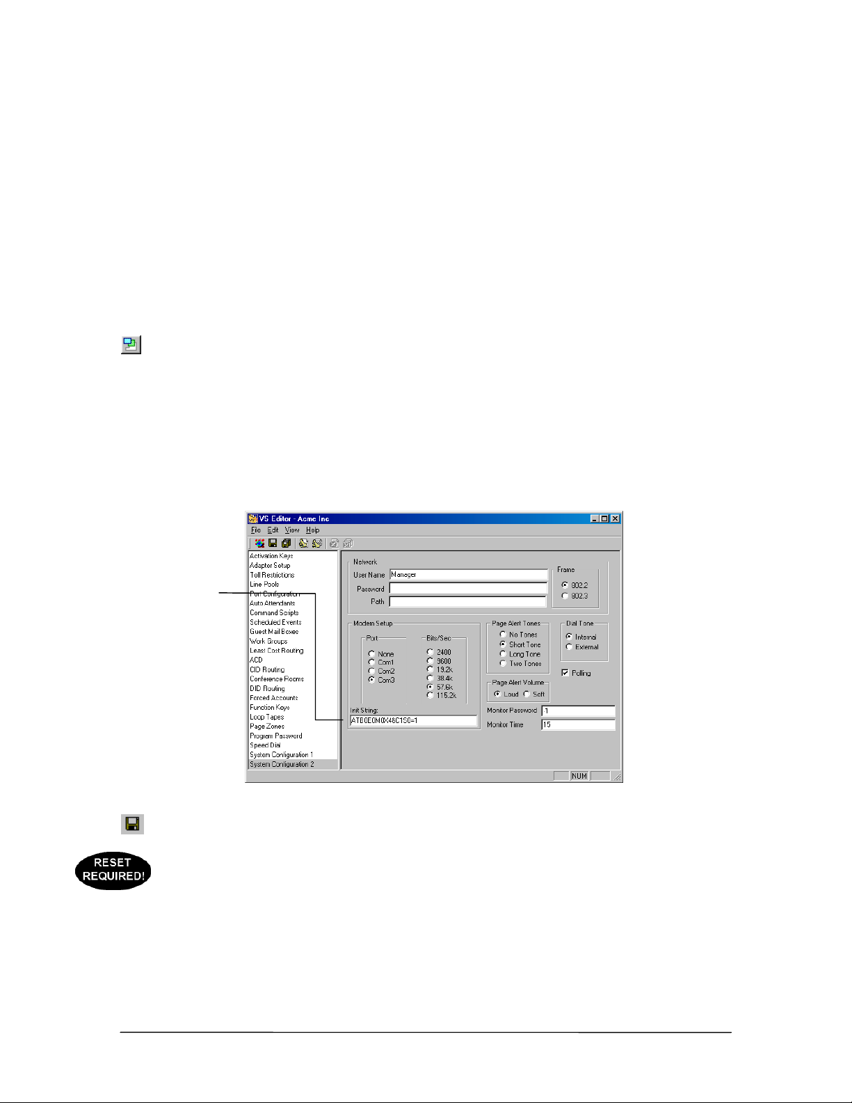
Dedicated CO Line to TVS Modem Connection (off-site access)
With this connection method, the Tel-Site application dials the site and waits for the TVS modem to
answer and connect. The advantage of having a dedicated CO line for the TVS modem is the ease of
use and reliability of the connection. The disadvantage is that the CO line cannot be used for
anything other than the TVS modem.
TVS Configuration
For a Dedicated CO to Modem Connection, you must configure the TVS modem to answer the TelSite modem call.
1. With the site open through Tel-Site, click the Configuration window button in the toolbar.
2. Click the VS1 Editor button.
• The VS1 Editor configuration program opens.
3. In the Tree Control display, click System Configuration 2.
4. In the Init String: text box, check that the end of the modem initialization string reads S0=1.
(S0=1 sets the modem to answer on the first ring.) By default, this setting is already in place.
Modem
initialization string
Modem initialization
string for Dedicated
CO Line to TVS
Modem connection
5. Click the Save button in the toolbar.
6. If step 4 had to be changed from the default setting, use your current connection method (such
as the default on-site connection) to upload the new settings to the customer TVS and reload the
changes. See “Tel-Site Basic Operation” on page 76.
VS1 Installation, Configuration & Operating Guide 67
Page 80
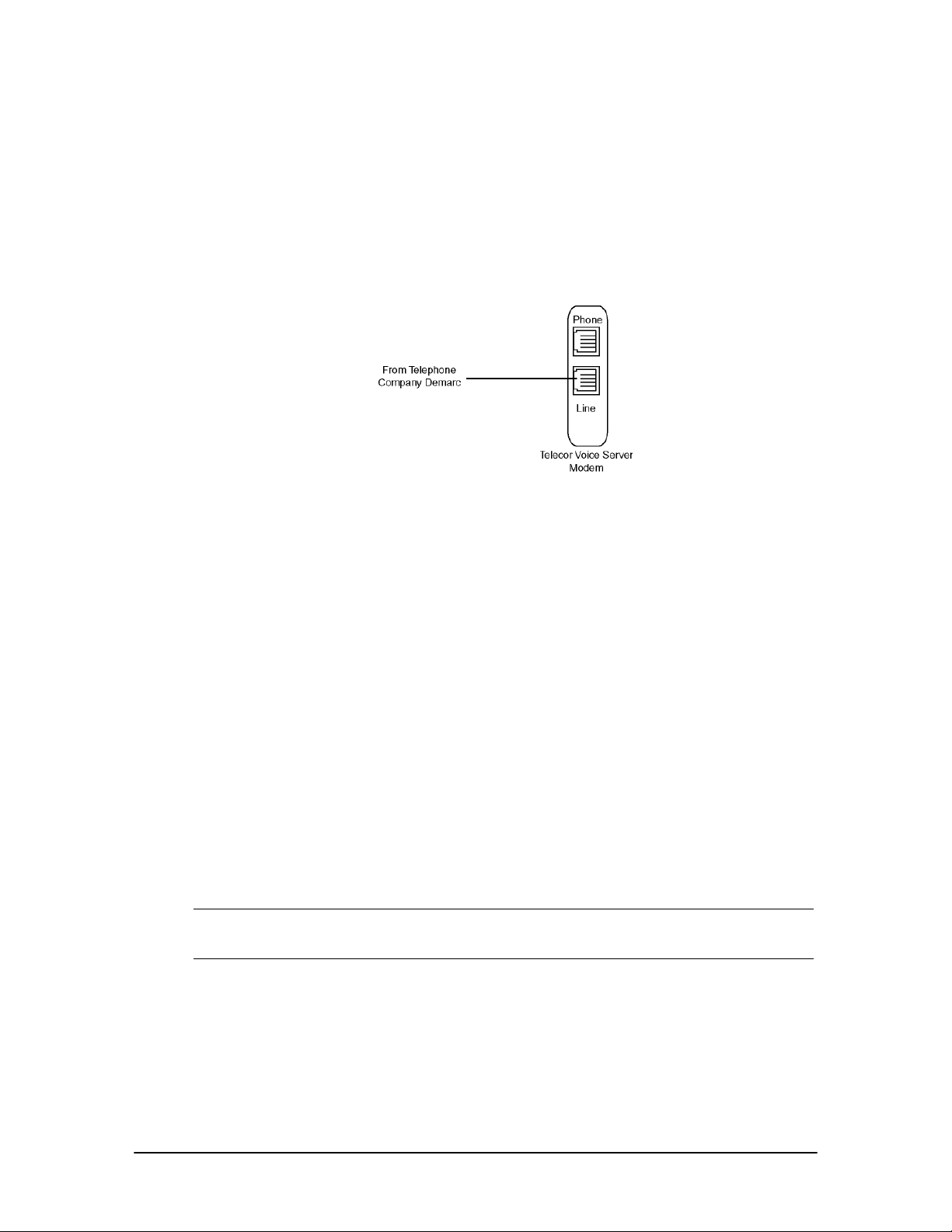
Hardware Setup
Prior to making the necessary hardware changes, ensure the TVS is configured to support the
Dedicated CO Line to TVS Modem connection (see page 67).
The diagram below shows the hardware setup for a dedicated CO line connection. A CO line from
the telephone company demarc is run to the line jack of the TVS modem.
Dedicated CO Line to
TVS Modem (off-site
access)
Tel-Site Setup
For a Dedicated CO Line to TVS Modem connection, Tel-Site must be set up so that it can dial the
phone number of the CO line plugged into the line jack of the TVS modem.
1. From the File menu, click Site Selection.
• The Site Selection window appears.
2. Select the site from the Site Name column.
3. Click Edit Site.
• The Connection dialog box appears.
4. If an RSA password is required to enable the Tel-Site modem to communicate with the TVS,
enter it in the RSA password text box. See “Remote System Access (RSA) Password” on page
78 for more information.
5. In the Phone number text box, enter the phone number of the CO line plugged into the line
jack of the TVS modem.
Note When specifying the customer site phone number, you can either specify the number
explicitly (using a 9 to get an outside line, for example) or use Standard Number Format.
See the Tel-Site Help topic Standard Number Format for more information.
6. In the Dialup connection information group box, ensure The modem shares a CO line check
box is cleared.
68 Tel-Site System Management Application
Page 81
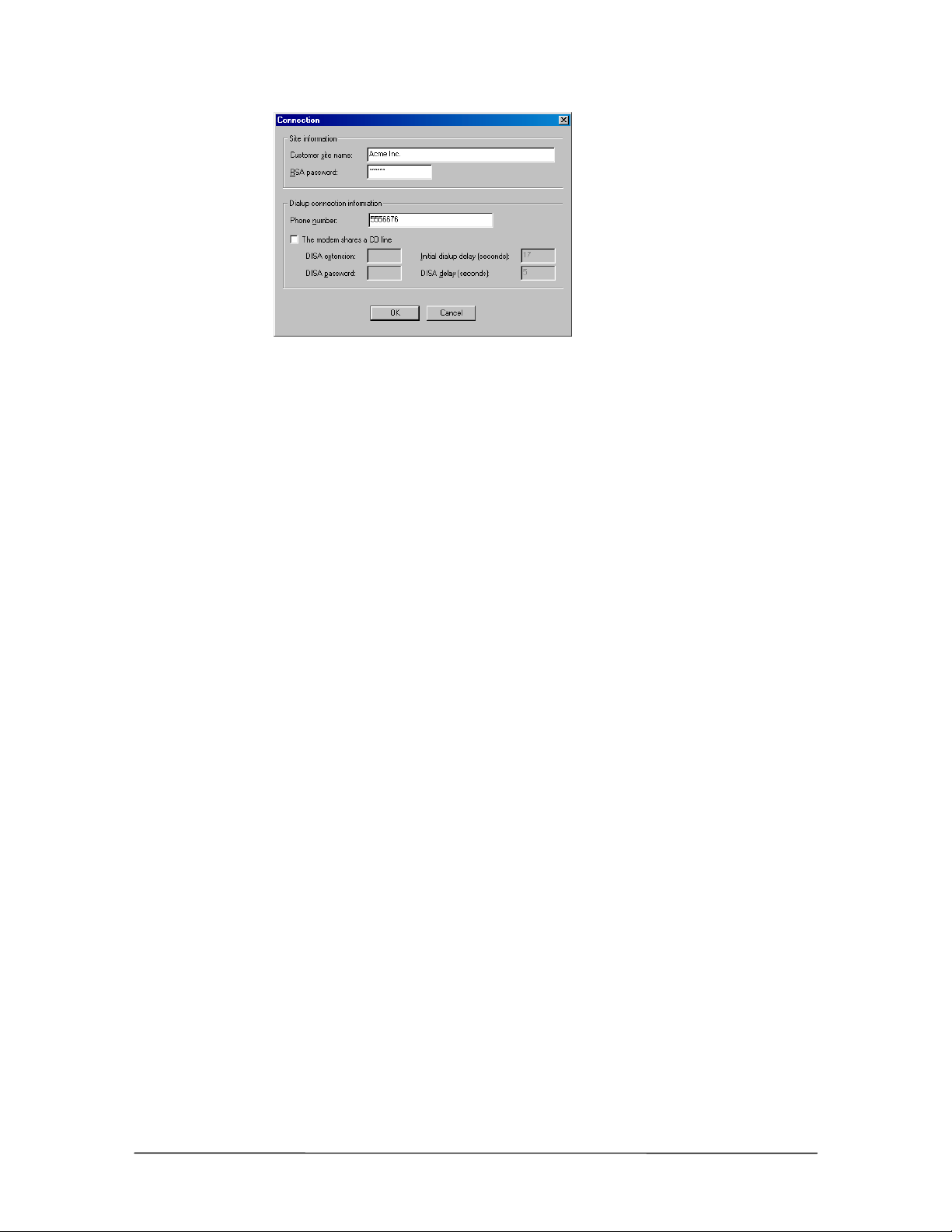
Setup in Connection
dialog box for
Dedicated CO Line
to TVS Modem
connection
7. Click OK to return to the Site Selection window.
8. Click OK to return to the Connection window.
9. See “Tel-Site Basic Operation” on page 76 to:
• Connect to a site
• Download files from a site
• Change site configurations
• Assign an RSA (Remote System Access) password
• Upload files to a site
• Reload configuration changes
Dedicated CO Line to TVS Modem Connection Checklist
In the System Configuration 2 pane of the VS1 Editor program, set the modem to
answer on the first ring.
Using your current connection method, upload the new configuration setting (only if
changed from default) to the customer TVS and reload the changes.
Connect the CO line from the telephone company demarc to the line jack of the TVS
modem.
In the Connection dialog box of the Site Selection window, enter an RSA password if
required.
Enter the phone number of the CO line plugged into the line jack of the TVS modem.
Ensure The modem shares a CO line check box is cleared.
VS1 Installation, Configuration & Operating Guide 69
Page 82

TVS Modem Shares a CO Line Connection (off-site access)
Sharing a CO line for a connection is a common way to access remote sites. This section describes
the TVS configuration required for a successful connection. In addition, you learn why Tel-Site uses
DISA (Direct Inward System Access) accounts and where to enter that information.
Note The modems used for shared CO connections must support partial dialing. Partial dialing
enables Tel-Site to dial the customer site, delay long enough for the TVS to answer, and
then send a Direct Inward System Access (DISA) logon password to complete the
connection. For more information, see the Modem Properly Installed topic in the Tel-Site
Help menu.
About Direct Inward System Access (DISA)
The TVS Modem Shares a CO Line connection uses DISA (Direct Inward System Access) as part
of its logon to the system. DISA is a way to gain access to the internal dial tone of the VS1
telephone system from an external phone not connected to the system. For example, you are off-site
and want to access an outside line from the office. You perform the normal DISA steps of pressing
#, then your extension, and then your DISA account.
DISA for the Tel-Site application uses the same procedures as normal DISA activity. The only
difference is that Tel-Site performs the steps automatically to connect.
TVS Configuration
For TVS Modem Shares a CO Line connection, the following steps must be completed:
• Configure the TVS modem to not answer the Tel-Site modem call.
• Enable DISA on the CO port connected to the TVS modem.
• Set up a DISA account on an extension port type
With the site open through Tel-Site, click the VS1 Editor button in the Configuration window.
This opens the VS1 Editor configuration program to make the above changes.
Configure the TVS modem to not answer the Tel-Site modem call
1. In the Tree Control display, click System Configuration 2.
2. In the Init String: text box, replace the current S0=[n] with S0=0 at the end of the modem
initialization string. (Typing S0=0 sets the modem so that it does not answer.)
3. Click the Save button in the toolbar.
70 Tel-Site System Management Application
Page 83
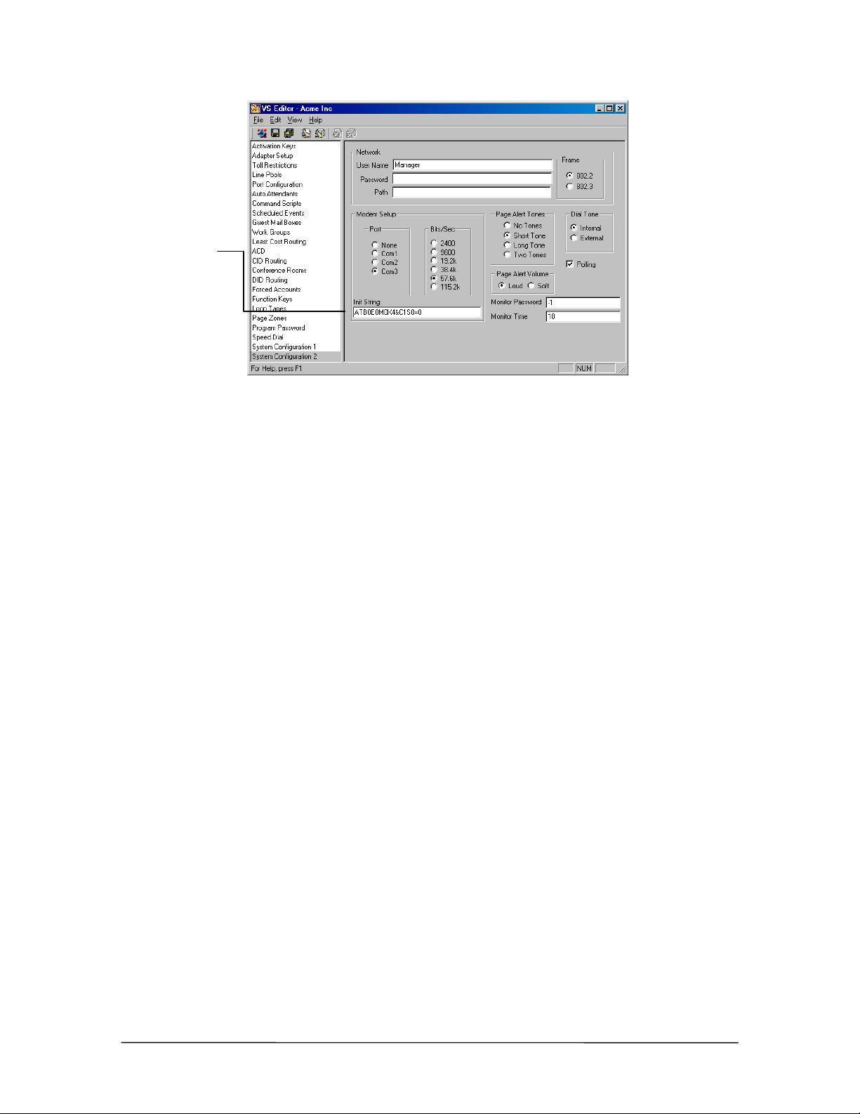
Modem
initialization string
Modem initialization
string for TVS
Modem Shares a CO
Line connection
Enabling DISA on the CO Port connected to the TVS modem
1. In the VS1 Editor Tree Control display, click Port Configurations.
2. In the Port Configurations pane, select the configuration where you want to make changes.
For example, select the DAY configuration.
3. Select the CO port that is shared with the TVS modem.
4. Under Rings, set the CO port to ring the first target for two rings.
5. Under Target Ports, set the target by typing null. (The null device doesn’t ring a physical
extension. It gives Tel-Site time to send the DISA sequence to the TVS.)
6. Set the number of rings for the remaining targets according to your configuration.
7. Select the DISA check box.
8. Make sure you replicate the changes made to this port in all configurations, not just for the
DAY configuration.
VS1 Installation, Configuration & Operating Guide 71
Page 84
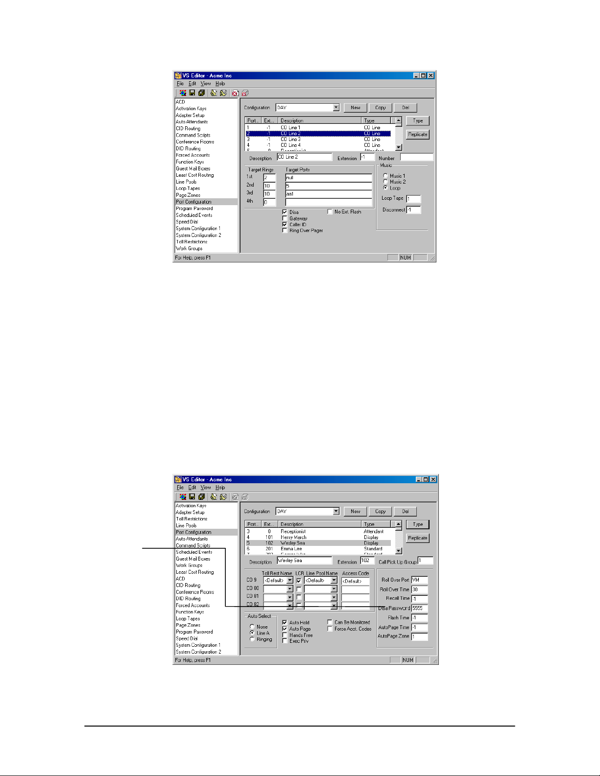
DISA setup on CO
Port
Setting up a DISA Password on an Extension Port
1. In the VS1 Editor Tree Control display, click Port Configurations.
2. In the Port Configurations pane, select the configuration where you want to make changes.
For example, select the DAY configuration.
3. In the Port Configurations pane, select the Extension port of a user you want to give a DISA
password.
4. In the DISA Password text box, enter a five-digit number ranging from 00000–99999. By
default, the DISA Password is set to –1, which means no password has been assigned, and no
DISA features are available for that extension.
5. Make sure you replicate the changes made to this port in all configurations, not just for the
DAY configuration.
DISA Password
text box
DISA Password on
extension port
72 Tel-Site System Management Application
Page 85
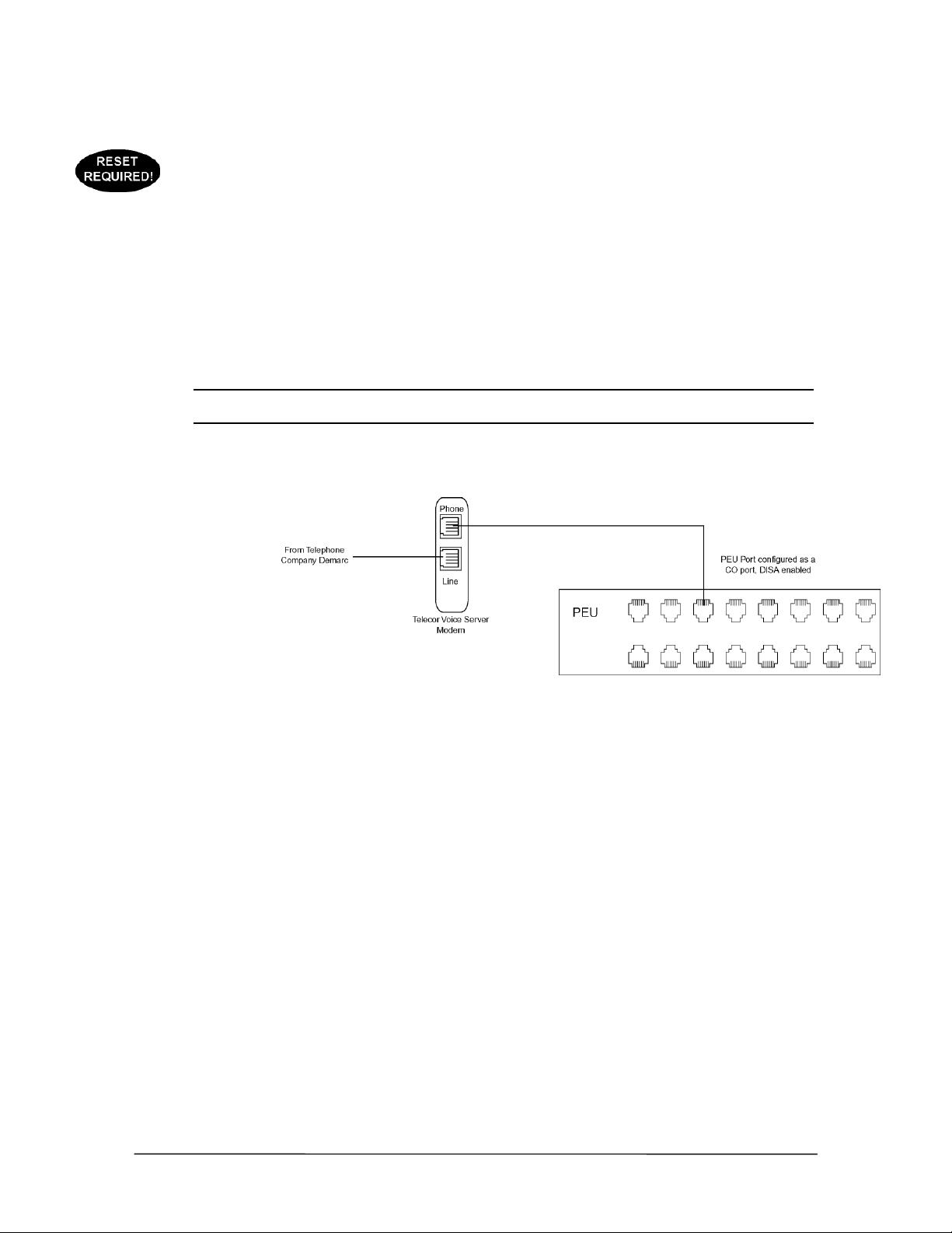
Uploading new settings and reloading changes
After the above settings have been configured, use your current connection method (such as the
default on-site connection) to upload the new settings to the customer TVS and reload the changes.
See “Tel-Site Basic Operation” on page 76.
Hardware Setup
Prior to making the necessary hardware changes, ensure the TVS is configured to support the TVS
Modem Shares a CO Line connection (see page 70).
The diagram below shows the hardware setup for a shared CO connection. The CO line from the
telephone company demarc is run to the line jack of the TVS modem. Another telephone cord is run
from the phone jack of the TVS modem to a CO port on the PEU.
Note: It is important that you share one of the least-used CO lines. Usually a CO line in the
middle of the inbound hunt group and outbound line pool is best.
TVS Modem Shares a
CO Line (off-site
access)
Tel-Site Setup
Tel-Site must be set up so that it can dial the phone number of the CO Line plugged into the line
jack of the TVS modem. It then must automatically dial the extension number set up with DISA and
the associated DISA account to complete the connection. Complete the following steps:
1. From the File menu, click Site Selection.
• The Site Selection window appears.
2. Select the site from the Site Name column.
3. Click Edit Site.
• The Connection dialog box appears.
4. If an RSA password is required to enable the Tel-Site modem to communicate with the TVS,
enter it in the RSA password text box. See “Remote System Access (RSA) Password” on page
78 for more information.
VS1 Installation, Configuration & Operating Guide 73
Page 86
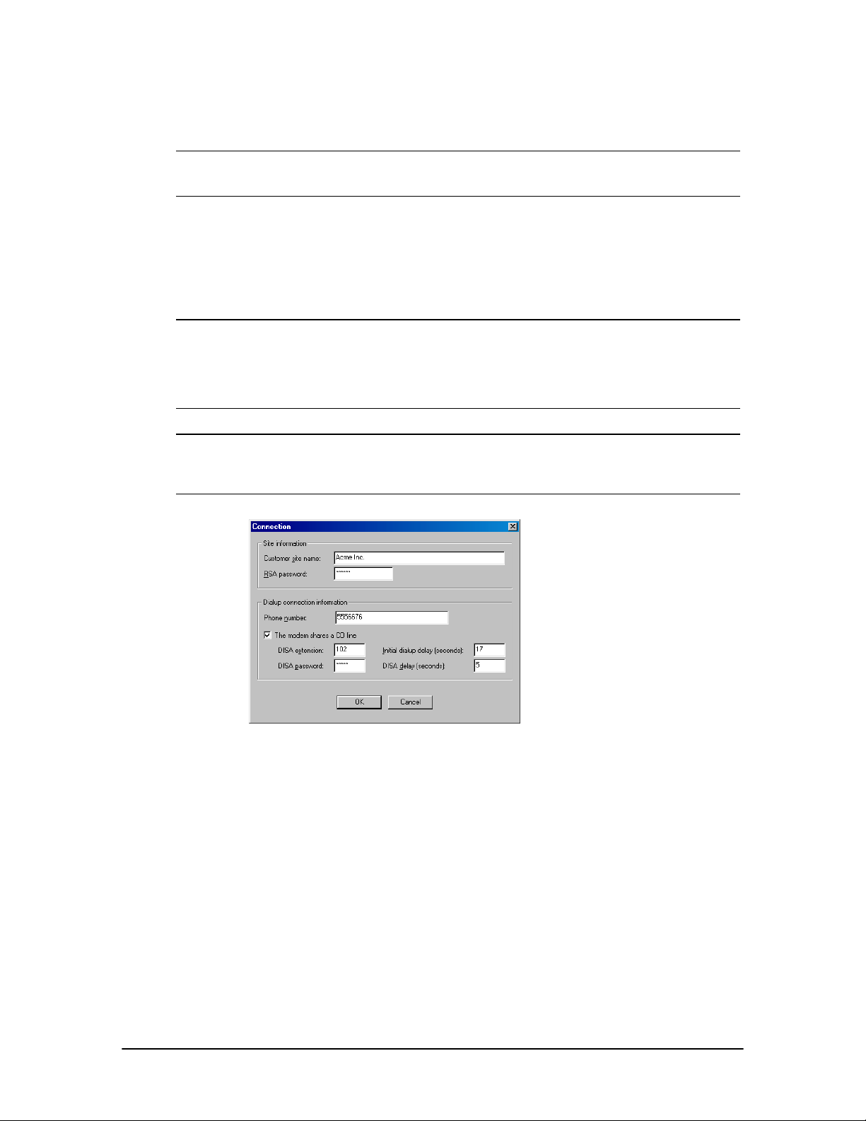
5. In the Phone number text box, enter the phone number of the CO line plugged into the line
jack of the TVS modem.
Note When specifying the customer site phone number, you can either specify the number
explicitly (using a 9 to get an outside line, for example) or use Standard Number Format.
See the Tel-Site Help topic Standard Number Format for more information.
6. In the Dialup connection information group box, select The modem shares a CO line check
box.
7. In the DISA extension text box, enter an extension set up with a DISA password.
8. In the DISA password text box, enter the associated DISA password for the extension.
Note 1 Generally, the default value of five seconds for the DISA delay does not need to be
changed. However, the Initial dialup delay may need to be changed. If the default setting
does not work, connect a phone to the phone jack on the modem and listen in parallel
while the modem tries to connect. Count the number of seconds between the time of the
last digit dialed and after the first ring back, and then enter that number in the Initial
dialup delay text box.
Note 2 If your modem speaker is set loud enough for you to hear the ring backs, you can listen for
the Voice Server ring back, and then press Shift while clicking the Connect button. This
will cause Tel-Site to send the DISA logon immediately instead of waiting for the Initial
dialup delay time to expire.
Setup in Connection
dialog box for TVS
Modem Shares a CO
Line connection
9. Click OK to return to the Site Selection window.
10. Click OK to return to the Connection window.
11. See “Tel-Site Basic Operation” on page 76 to:
• Connect to a site
• Download files from a site
• Change site configurations
• Assign an RSA (Remote System Access) password
• Upload files to a site
• Reload configuration changes
74 Tel-Site System Management Application
Page 87

TVS Modem Shares a CO Line Connection Checklist
In the System Configuration 2 pane of the VS1 Editor program, set the modem so it
does not answer.
In each configuration, enable DISA on the CO Port connected to the TVS modem.
On the same extension port in each configuration, set up a DISA password.
Using your current connection method, upload the new configuration to the customer
TVS and reload the changes.
Connect the CO line from the telephone company demarc to the line jack of the TVS
modem.
Connect a standard telephone cord from the phone jack of the TVS modem to a DISA-
enabled CO port on the PEU.
In the Connection dialog box of the Site Selection window, enter an RSA password if
required.
Enter the phone number of the DISA-enabled CO line plugged into the line jack of the
TVS modem.
Select The modem shares a CO line check box.
Enter the extension set up with a DISA password. Enter the associated DISA password
for the extension.
VS1 Installation, Configuration & Operating Guide 75
Page 88
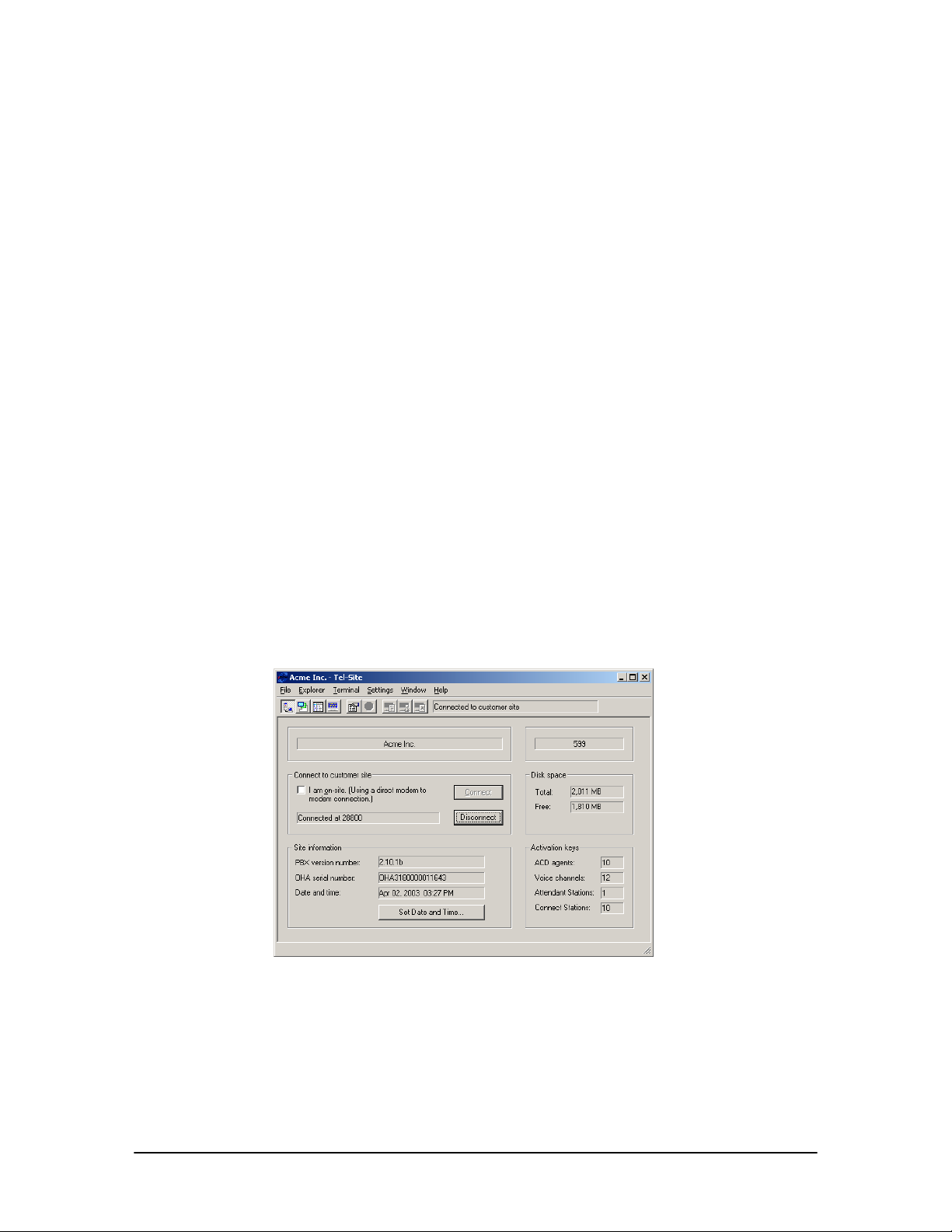
TEL-SITE BASIC OPERATION
The Tel-Site system management application enables you to make site changes in five steps after
you have set up a profile for that site. These steps are:
1. Connecting to a site.
2. Downloading any files that have changes from a site.
3. Changing those files on your local computer using VS1 Editor.
4. Uploading those changes to the site.
5. Reloading those changes to put them in effect
Connecting to a Site
The Connection window for Tel-Site appears when the application is first started. Before you can
connect to a site using Tel-Site, you must first make hardware, wiring, and system configuration
changes. See “Connection Methods,” page 58.
1. From the File menu, click Site Selection.
• The Site Selection window appears.
2. Select the site from the Site Name column.
3. Click Open.
4. In the Connection window, click Connect.
5. Tel-Site dials the site, logs on, and supplies any necessary passwords to complete the
connection.
Connection window
76 Tel-Site System Management Application
Page 89
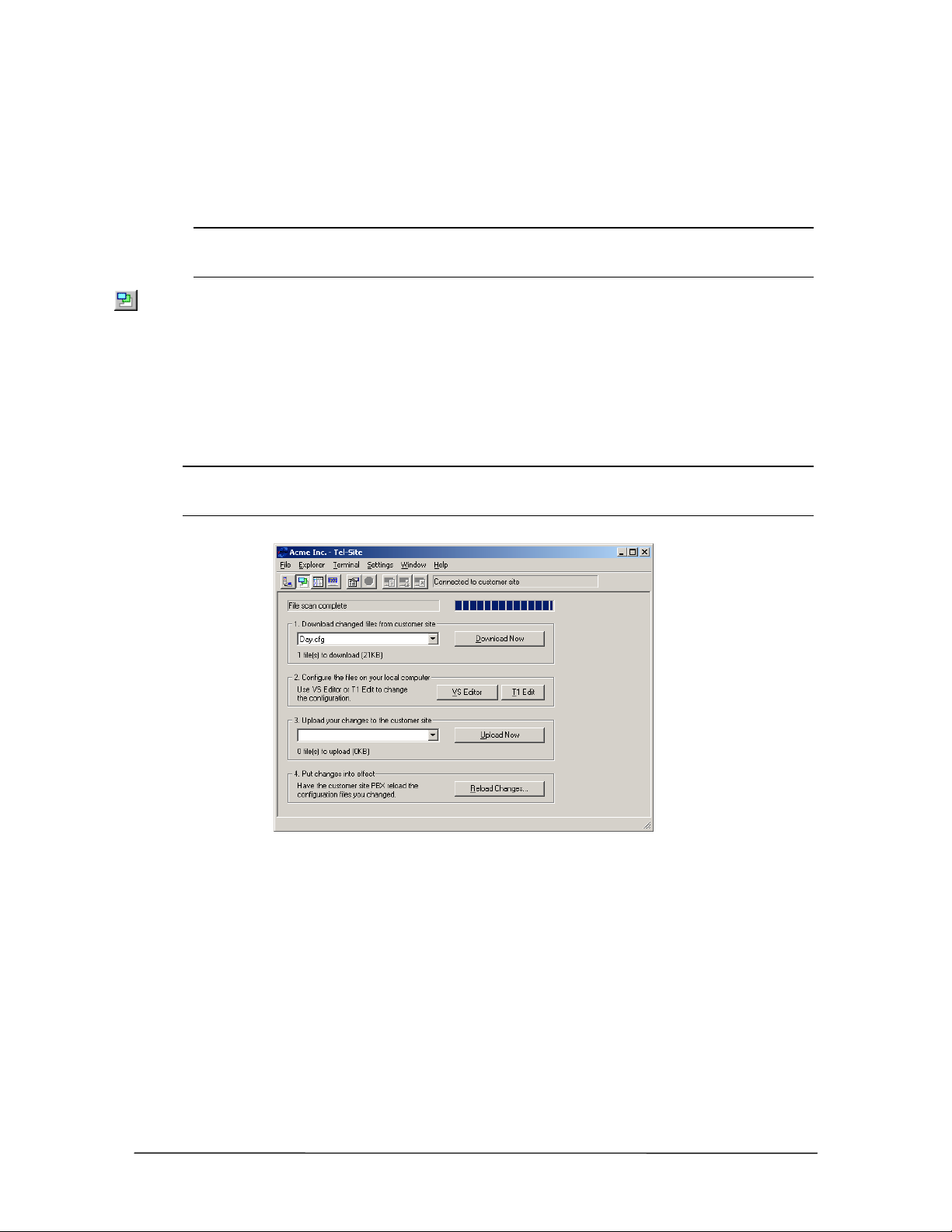
Downloading Files from a Site
When connected to a customer site and the Configuration window is opened, Tel-Site scans and
displays any TVS files that have changed since the last remote activity. It can then download any
updated files so that your local computer matches the latest customer site configuration.
Note The first time you open the Configuration window after upgrading the TVS software, a
dialog box opens indicating an upgrade has occurred. You must download all of the
Configuration files so they correspond with the latest VS1 software version.
1. On the toolbar, click the Configuration window button.
2. Wait for Tel-Site to scan the files on the TVS. After scanning, files that need to be downloaded
appear in the Download changed files from customer site drop-down list box. If no files have
changed, the drop-down list box is empty.
3. Click Download Now to download the files to your local computer. For example, the screen
below shows file Day.cfg has changed since the last remote activity.
Warning! Clicking the Download Now button when there are no files present causes Tel-Site to
download all the configuration files from the site. This should be done only if you believe
the Tel-Site application failed to detect changed files.
Download remote
files
Changing Site Configurations
Configuration changes are performed on copies of site files on the Tel-Site computer. After any
changed customer site files are downloaded to the Tel-Site computer to match the latest customer
site configuration, the VS1 Editor program is used to configure the files.
1. In the Configuration window, click the VS1 Editor to open the VS1 Editor configuration
program.
2. Change the system configuration files as needed. See the VS1 Editor section for information .
VS1 Installation, Configuration & Operating Guide 77
Page 90
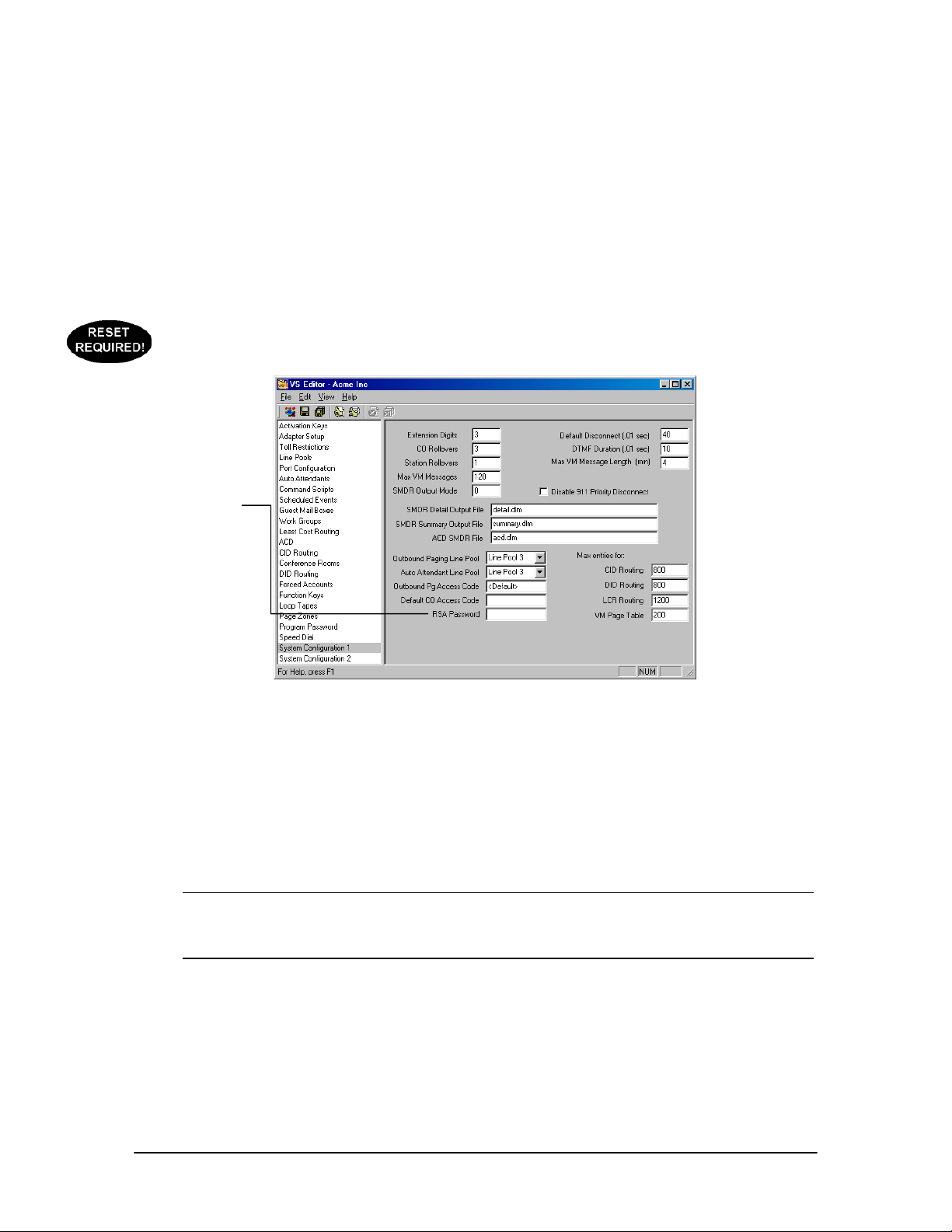
Remote System Access (RSA) Password
The TVS can be set up with a password to enable a remote modem to communicate with the system.
To assign a RSA password to the TVS, complete the following steps.
1. In the Tree Control display of the VS1 Editor program, click System Configuration 1.
2. In the RSA Password text box, assign a password. The password can be alphanumeric. Leaving
3. Click the Save button in the toolbar.
4. Upload the password to the customer TVS and reload the changes (see page 79).
RSA Password
the box blank means there is no password.
System
Configuration 1 pane
Uploading Files to a Site
After making changes using VS1 Editor, the drop-down list box for Upload Now in the
Configuration window shows the configuration files that have changed. For example, Day.cfg.
1. Click Upload Now to upload the files to the TVS at the customer site.
Warning! Clicking Upload Now when there are no files listed in the Upload your changes to
customer site drop-down list box causes Tel-Site to upload all the configuration files to
the site. You should do this only if you think Tel-Site failed to detect one or more
changed files on your computer.
78 Tel-Site System Management Application
Page 91
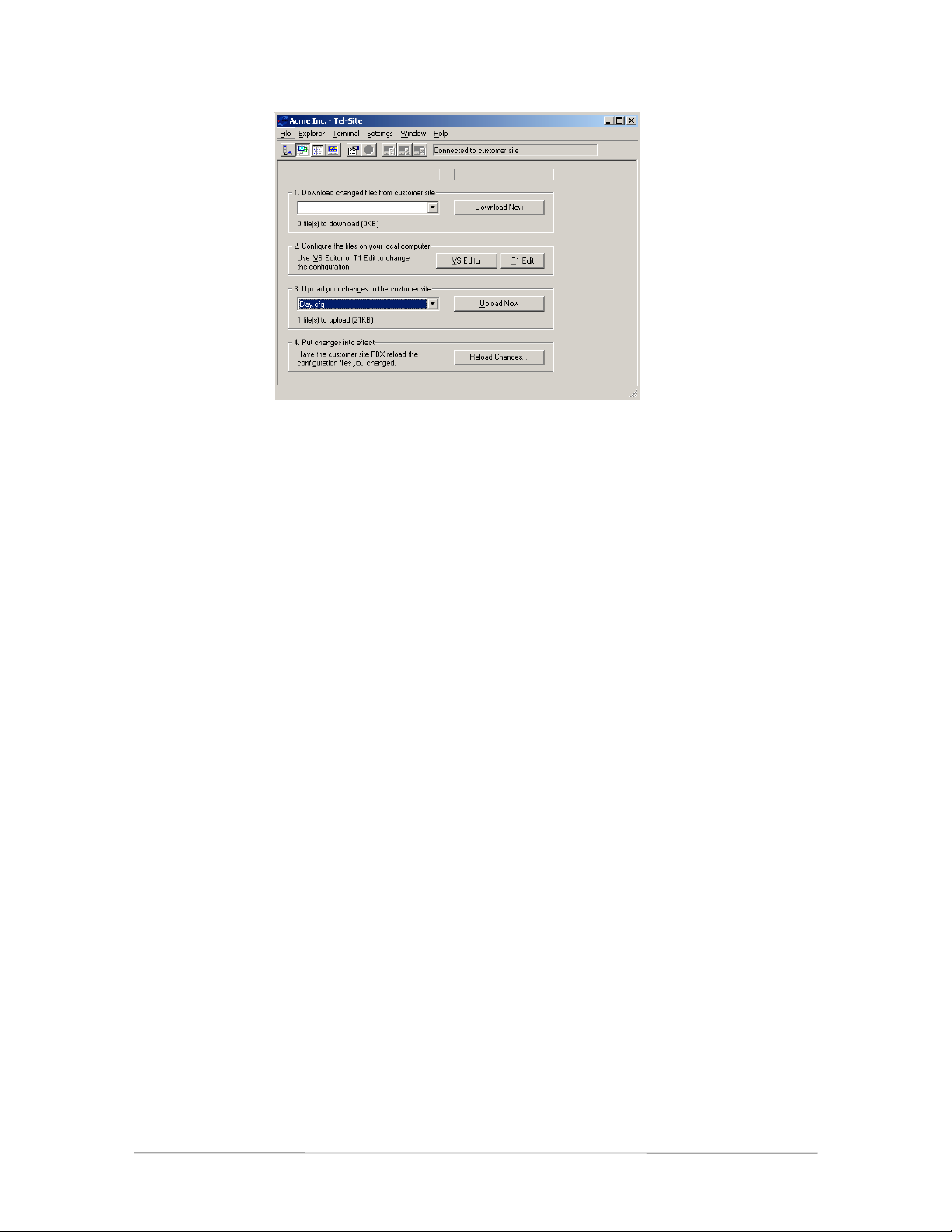
Upload files
Reloading Configuration Changes
Some configuration changes require a reset of the TVS. Resets should be made during periods of
low call activity, such as after-business hours. Call traffic is interrupted when the TVS is reset.
However, not all configuration changes require a system reset. To instruct the customer TVS to put
the changes in effect, complete the following steps:
1. Click Reload Changes.
• The Reload Changes dialog box appears.
2. In the Reload options group box, you can choose between a Standard reload, which is
recommended for all changes, or a T1 reload, which is used for changes to T1 settings.
3. The Shutdown options group box is where the TVS is instructed to either reset to put
configuration changes into effect, or not to reset because the configuration changes made do not
require a system reset.
If a reset of the TVS is required, the reset should be made during periods of low call activity,
such as after business hours. Call traffic is interrupted when the TVS is reset.
VS1 Installation, Configuration & Operating Guide 79
Page 92
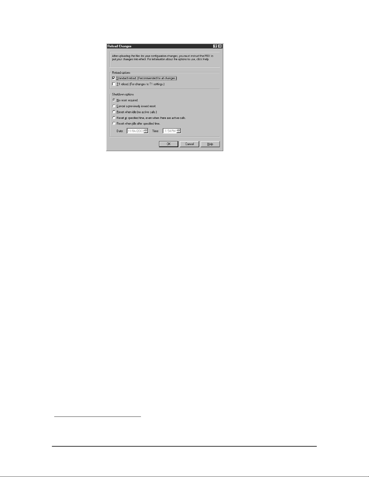
Reload changes
System Reset Required
If any of the following items are changed with the VS1 Editor and uploaded to the server, a system
resest is required.
• ACDs
• Adapter Setup
• Activation Keys
• Auto Attendants (except extension numbers)
• Auto-Select in Extension Port Configuration
• AutoPage in Extension Port Configuration
• Conference Rooms
• Function Keys
• Forced Account Codes1
• Guest Mailboxes
• Handsfree in Extension Port Configuration
• Loop Tapes
• Page Zones
• Port Types
• System Configuration 1-2
• Work Groups
1
A System Reset for Forced Account Codes is only required if changing the number of digits or changing
between verified and non-verified.
80 Tel-Site System Management Application
Page 93

VS1 Editor
Page 94
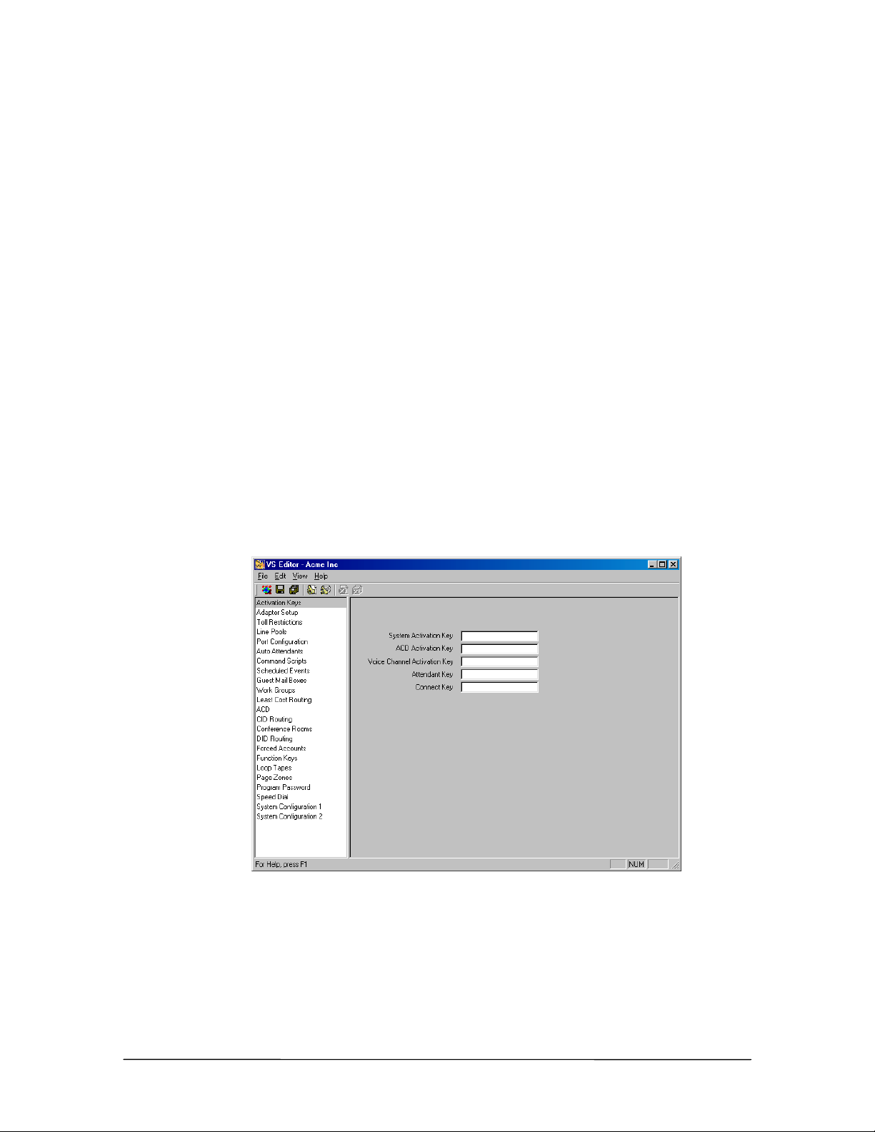
OVERVIEW OF VS1 EDITOR
The VS1 Editor application allows a VS1 Telephone System to be configured for operational use.
All system configuration settings and properties are set up and controlled using this application.
VS1 Editor can be opened independently or can be opened through Tel-Site via the Configuration
window.
The VS1 Editor application is available for download from the VS1 Dealer Page of the Telecor Web
Site (www.telecor.com). Please visit the page for details on licensing information and installing the
application.
In addition, the VS1 Editor can be installed with limited features to allow end-users the ability to
make common changes to the VS1 system without risk of modifying or damaging important
configuration data (see VS1 Editor – Limited Feature Version, page 168).
The VS1 Editor application is a Windows®-based program that operates on Microsoft® Windows
98, Windows® 2000, and Windows® XP operating systems.
The left pane consists of the Tree Control, which by default displays items in a logical order.
Logical order means that the items are displayed in an ideal top-to-bottom sequence that can be
followed when configuring a VS1 System. Clicking on an item brings up its accompanying pane to
the right.
The order in which the items are displayed in the Tree Control can be changed from logical to
alphabetical by selecting View > Order from the menu bar. The order in which each pane is
described in this section is Alphabetical
®
Activation Key pane
appears when VS1
Editor is opened
VS1 Installation, Configuration & Operating Guide 83
Page 95

ACTIVATION KEYS
The VS1 system controls software features through the use of Activation Keys. Activation Keys
“turn on” or activate certain VS1 phone system options purchased from Telecor. Activation Keys
are linked to the Telecor Voice Server (TVS) System ID Number (OHA Serial Number) and only
activate software installed on that TVS.
The software options that require Activation Keys include:
• System Activation Key (version specific)
• Automatic Call Distribution (ACD) Agent Package (for every 5 agents)
• Voice Channel Activation (for every 4 voice channels)
• Telecor Attendant CTI client application
• Telecor Connect CTI client application
Receiving Activation Keys
Each software option has its own Activation Key Request card that arrives in the box shipped to you
from your distributor. There are four steps you must follow in order to receive your software
Activation Keys from Telecor.
1. Review the Activation Key Request card number for each option purchased. The Activation
Key Request card number is a 13-digit number similar in pattern to the following example: 00000000-00000.
2. Call Telecor Technical Support.
3. Give the Technical Support representative the Activation Key Request card number and the
System ID Number (OHA Serial Number) for the TVS on-site.
• OHA numbers can be found in three areas: the shipping package; in the Connection
window of Tel-Site, or by typing sysinfo at the TVS Command prompt.
4. The Technical Support representative generates a 12-digit Activation Key for each option.
84 VS1 Editor Configuration Application
Page 96
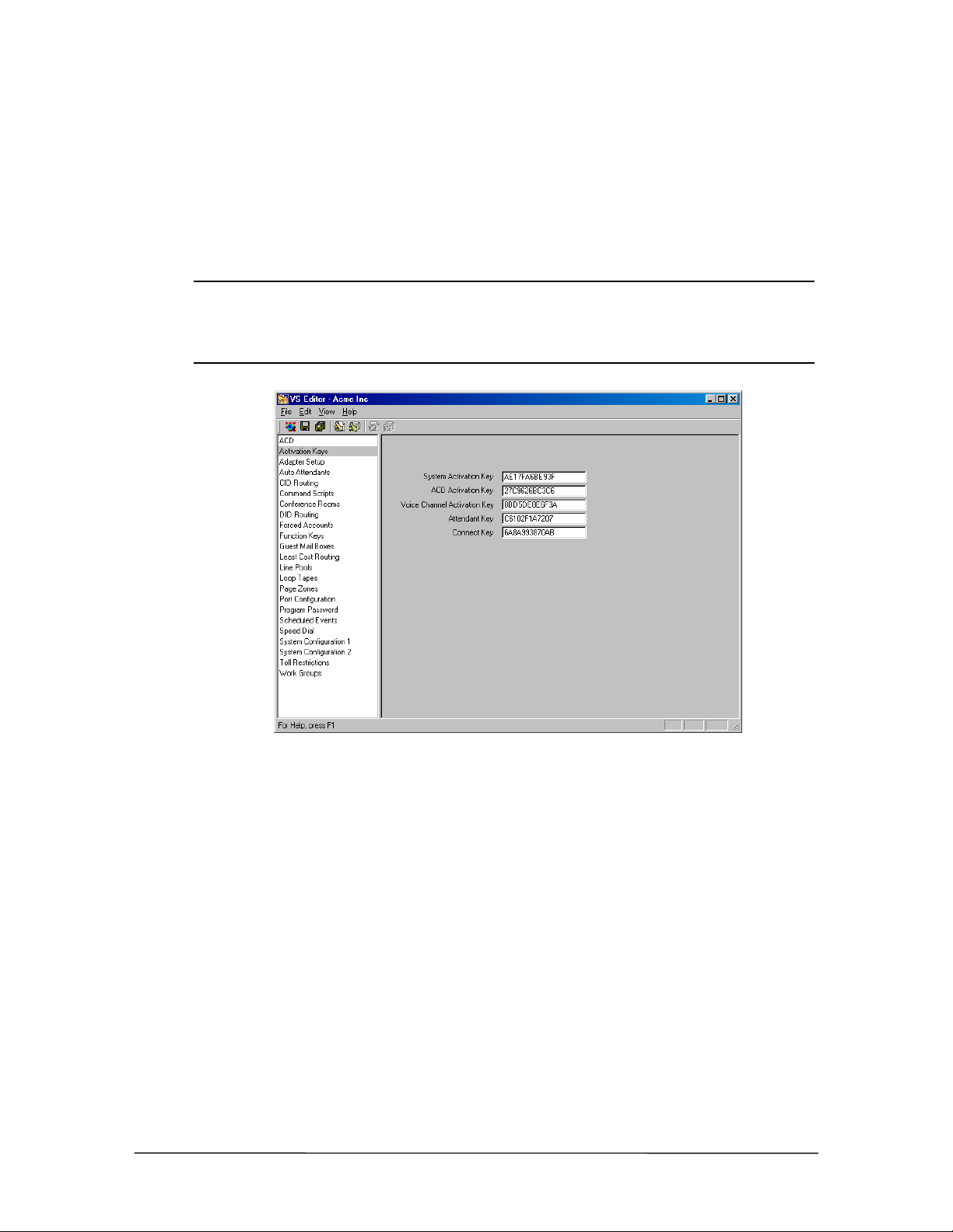
Installing Activation Keys
1. Click Activation Keys in the Tree Control display.
2. In the Activation Keys pane, type the 12-digit code in the appropriate software option text
boxes.
3. Click the Save button in the toolbar.
Note Each Host Adapter Card has a unique Serial Number. The TVS uses the Serial Number of
the first Host Adapter Card (ports 1-32) as the System ID Number. The System ID
Number is used to authenticate Activation Keys for that particular TVS. If the Host Adapter
Card is configured for ports 1-32 is replaced, you must call Technical Support for new
Activation Keys.
Activation Key pane
VS1 Installation, Configuration & Operating Guide 85
Page 97
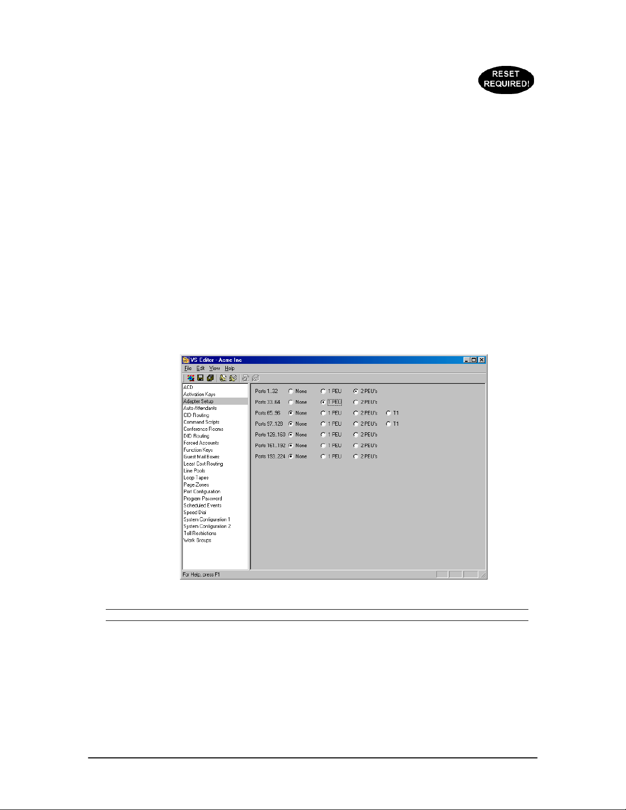
ADAPTER SETUP
Adapter Setup is required to indicate to the VS1 System what hardware is allocated for its ports. If
upgrading system hardware, Adapter Setup can save you time by enabling you to perform the
following actions before installing the new hardware:
• Change port types
• Change configurations
• Upload those configurations using Tel-Site
Complete the following steps:
1. Select Adapter Settings in the Tree Control display.
• The Adapter Settings pane appears.
2. For Ports 1..32 select if one or two PEUs are used. Repeat this step for additional ports.
3. If one T1 Card is installed, select Ports 97..128. If a second T1 Card is installed, select Ports
65..96.
4. Click the Save button in the toolbar.
Adapter Setup pane
Note Ports 193 to 224 are not applicable with 2.10 software and are reserved for future use.
86 VS1 Editor Configuration Application
Page 98

AUTOMATIC CALL DISTRIBUTION
Automatic Call Distribution distributes incoming calls in a logical pattern to available company
personnel. Incoming CO lines can be routed directly to an ACD or calls can also be transferred
manually to an ACD extension from any VS1 station or Auto Attendant. The ACD feature
immediately routes the calls to the first available agent. If the agent cannot immediately pick up the
call, the ACD system plays a message defined as the Primary Loop Tape. For example, the message
could say: “Thank you for calling XYZ, Inc. All our agents are helping other callers. Please hold for
the next available agent.”
Each caller hears the Primary Loop Tape message from the beginning. If the Primary Loop Tape is
currently being played, a new caller continues to hear ringing until the loop starts over. When the
Primary Loop Tape message concludes, the ACD feature automatically plays the Secondary Loop
Tape, if it is available. The Secondary Loop Tape message may consist of music or promotional
information. If a Secondary Loop Tape message is not available, the system can play music on-hold
from the music source connected to the dry contacts on the Port Expansion Unit Model 205 (PEU-
205) or the Dry Contact Unit (DCU). If no music is available, the caller hears silence. Both Loop
Tape messages are interrupted immediately when an agent answers the call.
There are 10 ACDs available on the VS1 System. A maximum of 95 agents can be logged on to the
10 ACDs, and a maximum of 30 callers can be in the ACD queue at any given time. The definition
of a logged on agent is a station option that is logged on to one or more ACDs. For example, if an
agent is logged on to three ACDs from a DP200 display phone, that agent is considered only as one
agent logged on to the system.
Call Distribution: Within an ACD, the standard method of call distribution is to route incoming
calls to the highest priority agent available (top-down distribution). If all available agents have the
same priority level, the incoming calls are routed to each agent in order (round-robin distribution).
Agents can log on to the ACD from any VS1 System station option except the Attendant CTI client
application. The system automatically recognizes the logged on station option and routes calls to
that station.
With the standard method, a call in the ACD is answered by the highest priority agent available, or
if all available agents have the same priority level, to each agent in order.
Warnings: The ACD also generates alert messages based on call criteria such as calls per agent
ratio, age of the oldest call in the queue, or if there are callers in queue but no agents logged on. The
alerts can be configured in several ways, but one approach is to have a voice message played over
the paging system (or over speakerphones) to alert the manager or supervisor.
An Activation Key code is required for ACD use on the VS1 phone system. An ACD Activation
Key will activate 5 agents. You will find an Activation Key Request card located in the shipment of
equipment from your distributor.
VS1 Installation, Configuration & Operating Guide 87
Page 99
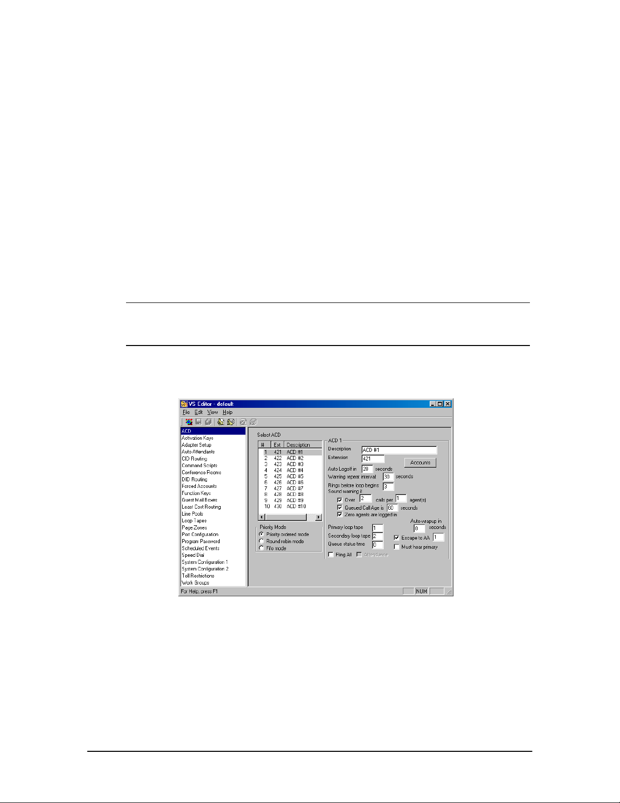
Creating an ACD
1. Click ACD in the Tree Control display.
• The ACD pane appears.
2. In the Select ACD box, select an ACD you want to configure.
3. In the Priority Mode group box, select how the calls are distributed amongst multiple ACDs:
• Priority Ordered Mode: This is the default setting. All calls in ACD #1 are answered,
then all calls in ACD #2 are answered, and so on.
• Round Robin Mode: The oldest call in the first called ACD is answered, then the oldest
call in the second called ACD is answered, and so on.
• FIFO Mode (First In First Out): The oldest waiting call is answered first, regardless of
the ACD queue that it is in.
Note The difference between Round Robin Mode and FIFO Mode is that in Round Robin Mode,
it is possible for the oldest call in the queue not to be answered first depending on what
ACD it is in. Whereas, in FIFO Mode, the oldest call is answered first regardless of the
ACD it is in.
4. Set up Account Codes for the ACD.
ACD pane
ACD Account Codes
Account Codes are used by agents to log on and log off the ACD system. Each Account Code has
an assigned priority to determine how calls in the ACD queue are routed. Up to 100 account codes
can be created for each ACD.
1. To add Account Codes for an ACD, select the ACD in the Select ACD box and then click the
Accounts button.
88 VS1 Editor Configuration Application
Page 100
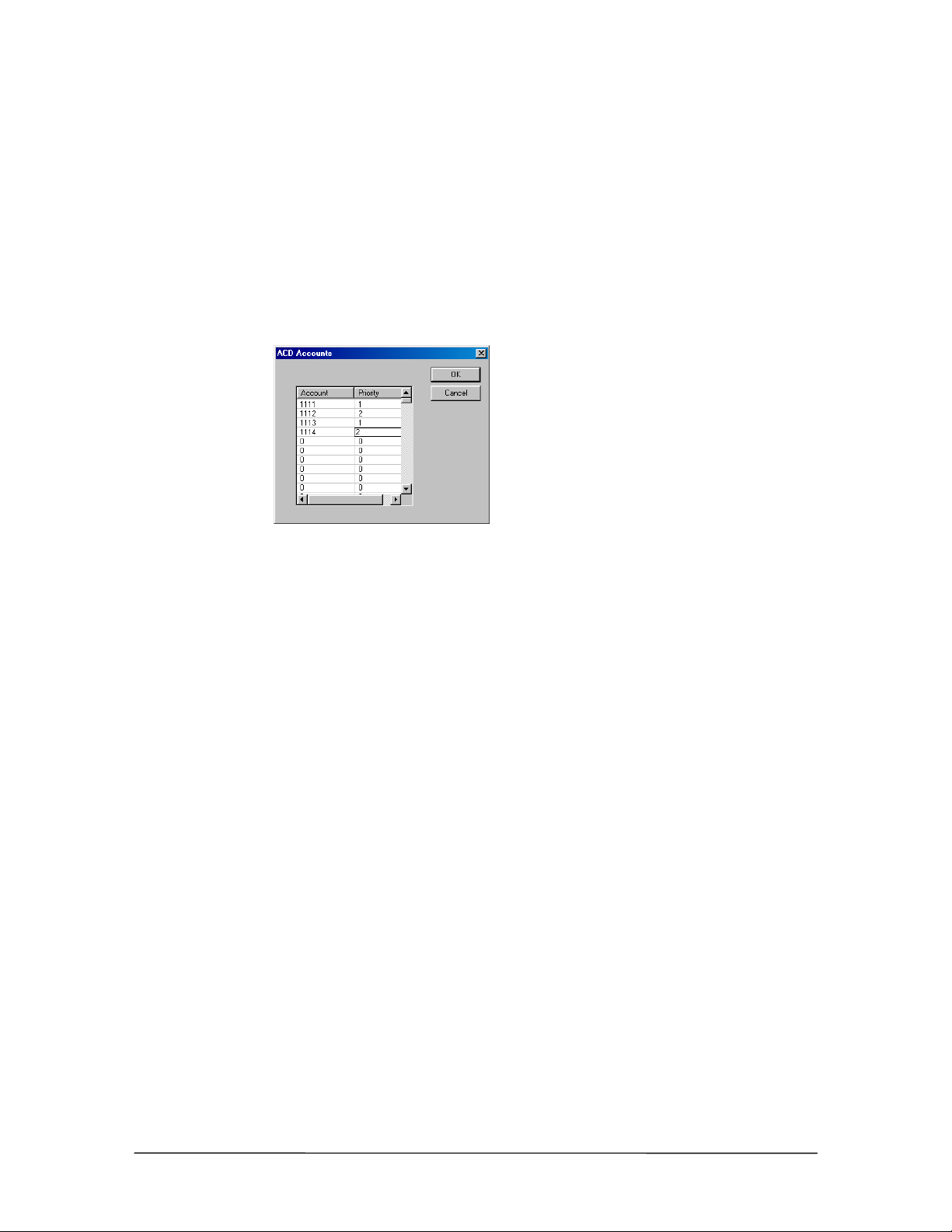
• The ACD Accounts window appears.
2. In a space under the Account column enter a unique Account Code of four digits. Do not
include spaces or other punctuation.
3. Beside to the newly-created Account code, under the Priority column, enter a Priority number
of one or two digits. When more than one agent is available on the ACD system, callers are
routed to the highest priority agent (top-down distribution). For example, if Agent A has a
priority level of 1, and Agent B has a priority level of 2, calls are routed to Agent A first. If all
available agents have the same priority level, the incoming calls are routed to each agent in
order (round-robin distribution).
ACD Accounts
window
4. Click OK to return to the ACD pane.
Agent Account Codes can be assigned to more than one ACD, enabling that agent to receive calls
from all ACDs in which their account code appears. Note that the account codes in multiple ACDs
can have different priority levels for each ACD.
ACD No. 1 ACD No. 2 ACD No. 3 ACD No. 4
1111-1 1111-2 1111-3 1111-3
1112-2 1112-1 1112-3 1112-4
1113-4 1113-2 1113-1 1113-3
VS1 Installation, Configuration & Operating Guide 89
 Loading...