

Page 1
TEL-125, TEL-250 Power Amplifier Manual
1114 Westport Crescent; Mississauga, Ontario; Canada; L5T 1G1 April 22, 1997
Phone: (905) 564-0801 Fax: (905) 564-0806 E:\T2-37\T2-M37.WP
The Telecor TEL-125 and TEL-250 Power Amplifiers deliver 125 Watts and 250 Watts of power, respectively. These amplifiers will accept
either balanced or single ended input sources. A sensitivity “Input Level” switch is provided to select 1 V (0 dB) or 100 mV (-20 dB) input
levels. A 25 V input signal can also be used if the optional PA-AM Power Amplifier Attenuator module is installed (for details, see the
PA-AM Power Amplifier Module Manual). Output terminals are provided for 4 Ω, 8 Ω, 25 V and 70 V speaker lines. The amplifiers have
current limiting circuitry on the output to protect the amplifiers from overloading. The amplifiers also have circuitry to protect them from
overheating. The TEL-125 and TEL-250 Power Amplifiers are both UL approved units (UL 813.)
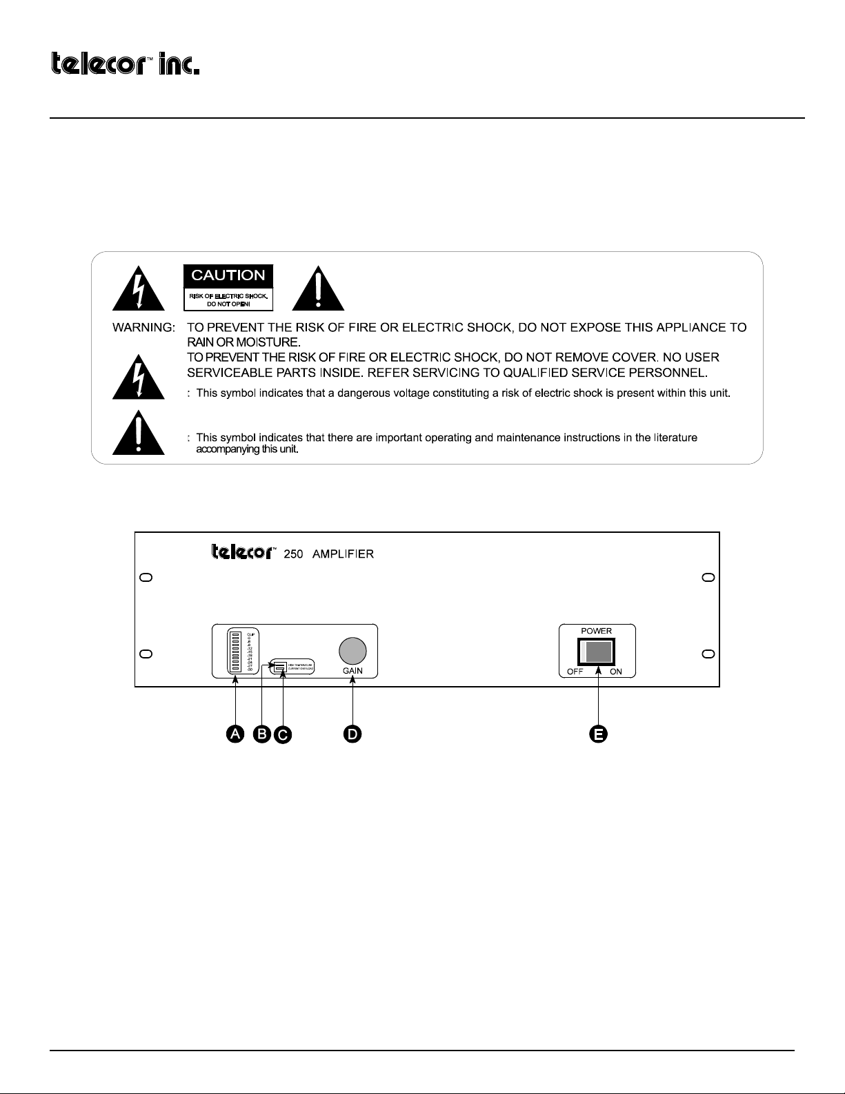
The various amplifier parts are indicated in the figures to follow:
Figure 1: Front View of Power Amplifier
A VU METER:
The 30 dB digital VU meter shows 0 dB when the amplifier is operating at its rated output. Exceeding the rated
output will cause the output to be clipped, which will be indicated by the illumination of the CLIP light.
B HIGH TEMPERATURE Light:
When the internal temperature of the amplifier exceeds its normal operating limit, the “High
Temperature” light will illuminate and the output level will begin to be reduced. The amplifier will continue to operate at a reduced
output level until the temperature returns to an acceptable level. If the “High Temperature” light is illuminated, see the section on
Troubleshooting.
C CURRENT OVERLOAD Light:
When the current output of the amplifier exceeds its maximum power output, the “Current
Overload” light will illuminate and the output level will begin to be reduced. The amplifier will continue to operate with the current
limiting circuit reducing the output power. If the “Current Overload” light is illuminated, see the section on Troubleshooting.
D GAIN Control:
The gain of the amplifier can be adjusted using this potentiometer. The potentiometer is concealed behind a snapon cover. The cover can be snapped off when the level needs to be adjusted but must be replaced to prevent unauthorized
tampering. The amplifier gain is set by both this control, and the sensitivity “Input Level” switch on the back of the amplifier.
E POWER Switch:
Turns the amplifier on and off. The switch will illuminate when the amplifier is turned on.
Telecor Administrative Communication Systems Page 1
Page 2
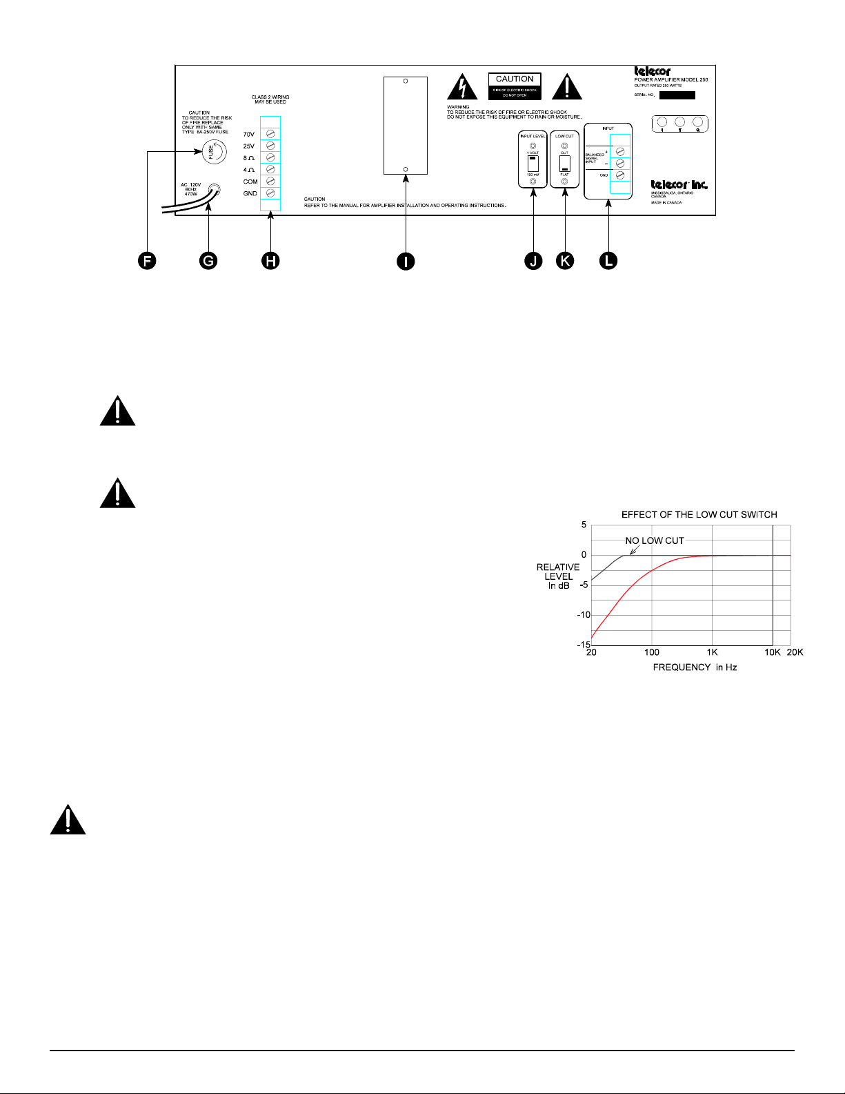
Figure 2: Rear View of Power Amplifier
F FUSE:
G AC Power Cord:
H OUTPUT TERMINALS:
Protects the amplifier if the maximum current draw is exceeded. If the fuse blows, see the section on Troubleshooting.
Connects the amplifier to a standard 120 V, 60 Hz grounded outlet.
Terminals are provided for 70 V and 25 V speaker lines, as well as 8 Ω and 4 Ω loads. Class 2 wiring
may be used.
Ensure the amplifier is OFF before making, removing or handling any output connections. The output terminal cover
must be in place when the amplifier is operating.
I ACCESSORY MODULE SLOT
the amplifiers. If no accessory module is installed, a blank cover plate must cover the slot.
Please note that the accessory modules are not user installable. They must be factory installed and ordered with the
amplifiers. Do not remove any modules or the cover plate.
J INPUT LEVEL:
The “Input Level” switch selects the range of the input level.
This switch works in conjunction with the “Gain” control on the front of the
amplifier. The “Input Level” switch should be set to match the level of the
input in either the 1 V or 100 mV range.
K LOW CUT:
The “Low Cut” switch will reduce the low end frequency response
of the amplifier as shown in Figure 3.
L INPUT TERMINALS:
The input terminals are electronically balanced with
an input impedance of 10 kΩ. The input signal level should be in either the 1V
or 100 mV range with the “Input Level” switch set to the appropriate position.
The GND terminal is provided, if required, for grounding the cable shield.
Installation
(for optional accessories): Several accessory modules are available which may be installed into
Figure 3: Relative Level (dB) vs. Frequency (kHz)
Before installing a TEL-125 or TEL-250 Amplifier, carefully inspect the device for any damages that may have occurred during shipping.
The shipping package should contain only the Power Amplifier. If any part of the amplifier has been damaged, please contact the shipping
company as soon as possible.
DO NOT ATTEMPT TO INSTALL EQUIPMENT THAT WAS RECEIVED DAMAGED.
The amplifier mounts into a standard 19" Telecor equipment rack with 10-32 screws. Both TEL-125 and TEL-250 amplifiers require 5 ¼"
of vertical rack space. When mounting an amplifier into a rack with other equipment, be sure to allow for adequate ventilation. To
accomplish this, ensure that a blank panel of 1 ¾" height (or greater) is installed between the amplifier and any other equipment (i.e.
additional amplifiers, power supplies, etc.) in the rack.
Do Not mount the amplifier such that: - there is inadequate ventilation.
- the top, bottom or side of the amplifier vents are covered or blocked.
- it is susceptible to vibration.
- it is in an area of high ambient temperature.
- it is adjacent to other heat radiating equipment.
- it is exposed to direct sunlight.
Page 2 Telecor Administrative Communication Systems
Page 3
The amplifier should be plugged into a standard three prong 120 V, 60 Hz grounded outlet. Turn the Power Switch off when connecting
and disconnecting the AC receptacle.
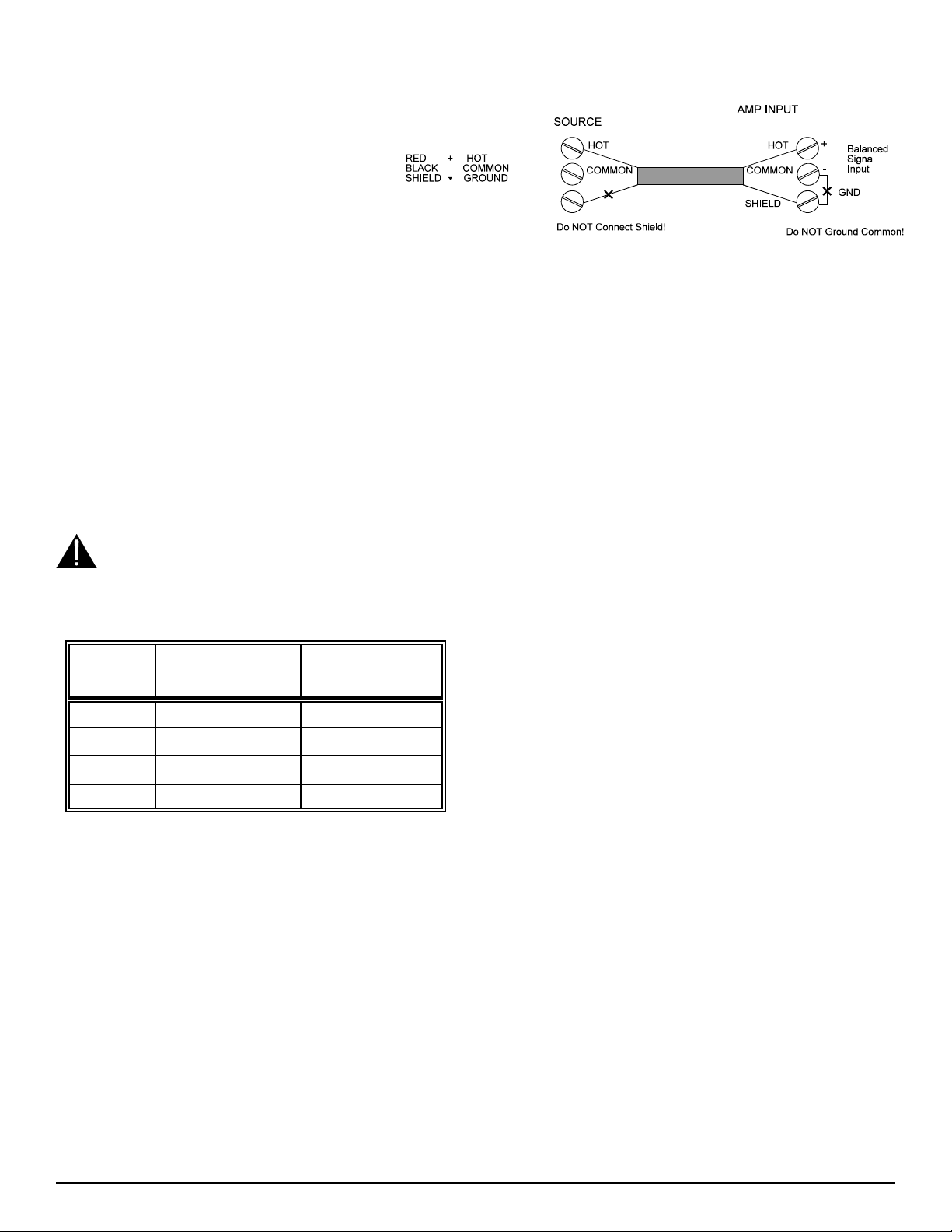
Input Connections: The screw terminals on the right
side of the back of the amplifier are for signal input.
The input terminals are suitable for both balanced and
single ended inputs. A ground terminal is provided for
grounding the shield of the cable if required. An
example of typical input wiring is shown in Figure 4.
Figure 4: Input Connections
To reduce the incidence of ground loop hum, oscillation, or interference from other audio sources:
1) Use a shielded cable for input wiring. The shield must be grounded at one end of the cable only, not at both.
2) Regardless of what type of input signal is supplied to the amplifier (balanced or single ended), the GND terminal should not
be connected to the - (common) terminal.
Set the “Input Level” switch to match the level of your input. If connecting the input of the amplifier to an unknown level signal, set the
“Input Level” switch to 1 V and the “Gain” to 0. Then apply the signal and increase the gain. If an unacceptable level is not reached with
the gain at maximum: turn the “Gain” to 0, switch the “Input Level” to 100 mV, and then increase the gain.
Output Connections: The left terminal strip is the signal output of the amplifier. Terminals are provided for 70 V and 25 V speaker
lines, as well as 8 Ω and 4 Ω loads. Connect the speaker load to the appropriate terminals depending on the load impedance. Class 2 wiring
may be used. The output of the amplifier is floating with respect to ground and should remain that way. Do not connect the COM and GND
terminals together. The GND terminal is provided for use with shielded cable only.
Ensure the amplifier is OFF before making, removing or handling any output connections. The output terminal cover must be
in place when the amplifier is operating.
To reduce the incidence of output audio being induced into other conductors, use twisted pair wiring and keep the input and output wiring
separated. To avoid overloading the amplifier, ensure that the total speaker load impedance is no less than the values in the table below:
Output
Terminals
70 V 39 Ω 19.5 Ω
TEL-125
Maximum Load /
Minimum Impedance
Maximum Load /
Minimum Impedance
TEL-250
Line Impedance Measurements: Measure the amplifier's load
impedance using an audio signal impedance meter (1 kHz) with the
amplifier output disconnected. Also, measure the impedance of each
side of the load to earth ground, which should be open circuit. If it is not
(i.e. there is a fault to ground), isolate the fault and correct it. Do not
25 V 5 Ω 2.5 Ω
8 Ω 8 Ω 8 Ω
operate the amplifier on a ground faulted output line. Note: In school
applications, there is often a privacy switch in the room which when
activated will ground one side of the room speaker line to ground
4 Ω 4 Ω 4 Ω
through a transformer. Make sure all these privacy switches are not in
the “Privacy” position when measuring line impedance to ground. These
switches do not adversely affect the operation of the amplifier. When
measuring load impedance on a Telecor installation: disconnect the amplifier output from the line, connect the impedance meter across the
line, make sure the system is in an ALL CALL mode, then measure the line’s impedance and check for line ground faults.
Operation
• Before turning the amplifier on, ensure that - the speakers have an adequate power rating.
- the proper output terminals have been used.
- the gain of the amplifier is appropriate for the input signal supplied.
• If you are unsure about the “Input Level” and “Gain” settings, turn the “Gain” control to minimum before turning the amplifier on.
• Once the amplifier is mounted and wired, turn the unit on. The Power Switch should illuminate. Watch the VU Meter on the front of
the Power Amplifier. With no signal connected, ensure that none of the LEDs are illuminated. If any LEDs illuminate, see the section
on Troubleshooting in this document.
• With the signal applied, adjust the “Gain” control until an appropriate output level is obtained. If the “Current Overload” or “Clip”
lights illuminate, see the section on Troubleshooting in this document.
• To reduce the low frequency amplification, set the “Low Cut” switch to the CUT position.
Telecor Administrative Communication Systems Page 3
Page 4
Troubleshooting
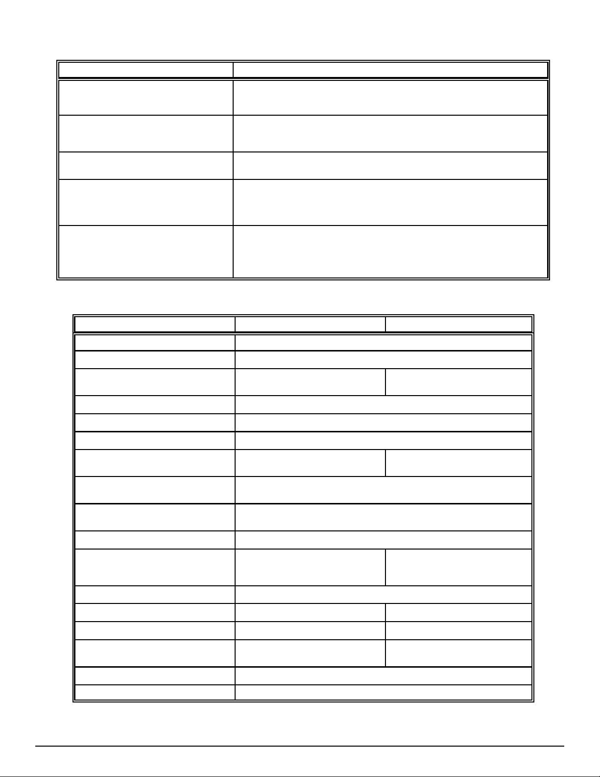
Problem Description
VU Meter registers a signal when no signal should
be present.
The “Current Overload” light illuminates or flashes.
The “Clip” light illuminates or flashes.
The “High Temperature” light illuminates.
Fuse blows.
Specifications
Characteristics: TEL-125 Power Amplifier TEL-250 Power Amplifier
Input Level
Input Impedance
The amplifier may be oscillating, possibly at a very high frequency. This may be caused by:
running input and output wires close together, grounding the input, or incorrect grounding of
shield.
This indicates that the amplifier is being overloaded. Check the total speaker load on the
amplifier. Also check for shorts in the output wiring, and for shorts to ground. If the amplifier
is being overloaded, reducing the load or the gain should solve the problem.
Reduce the output level of the amplifier either by turning down the “Gain” control or by
reducing the “Input Level”.
This indicates an excessively high temperature on the heat sinks. When this occurs, the
output level is reduced until the temperature returns to normal. Overheating of the heat sinks is
usually caused by insufficient ventilation or operating the amplifier in an overload state for an
extended period of time. Check the loading and ventilation of the amplifier.
This indicates excessive current draw by the amplifier. To replace the fuse, turn the amplifier
Power Switch OFF and unplug the amplifier from the AC receptacle. Unscrew the fuse knob
and replace the fuse with the same type, voltage and current rating as indicated on the amplifier:
TEL-125 amplifiers use a 3AG 250V 3A fuse, TEL-250 amplifiers use a 3AG 250V 8A fuse. If
new fuse also blows, unplug amplifier, contact Telecor Technical Support.
1 V or 100 mV (switchable)
10 kΩ (balanced)
(into balanced 4 Ω, 8 Ω, 25 V, or 70 V line)
Output
Frequency Response
Total Harmonic Distortion
Output Regulation (with Transformer)
Signal to Noise Ratio
(Band Pass 20 to 20000 Hz)
Connectors
Controls
Indicators
Protection
Temperature Range
Power Consumption
Weight
Dimensions
(without amplifier handles)
125 watts RMS 250 watts RMS
40 to 15000 Hz (± 1 dB)
0.05% @ 1 kHz rated output
< 1 dB, no load to full load
Input Level @ 0 dBv (1 V): > 94 dB Input Level @ 0 dBv (1 V): > 84 dB
Screw-Barrier Terminals on input and output.
Mas-Con connectors are used with optional modules.
Power Switch (Illuminated), Gain Control, Low Cut Switch,
“Clip”, “High Temperature”, “VU Meter” and “Current Overload” indicators
Foldback current limiting
Over-temperature protection
Primary circuit fused at 3 A
AC 120 V, 60 Hz, 180 W AC 120 V, 50 Hz, 340 W
11.8 kg (26 lbs.) 19 kg (42 lbs.)
5¼" H X 19" W X 11c" D 5¼" H X 19" W X 12c" D
Input Level Switch (1 V / 100 mV)
Foldback current limiting
Over-temperature protection
Primary circuit fused at 8 A
N
C to +60NC (12NF to 140NF)
-10
Approved Standards
Finish
50/50 Fine Texture Semi-Gloss Splatter Black
Specifications subject to change without notice.
UL 813
Page 4 Telecor Administrative Communication Systems
 Loading...