

Page 1
Intended for use with
eCLK-2.5-PoE and eCLK-4-PoE
November 2013
Rev 0.1
Telecor Inc.
1114 Westport Crescent
Mississauga, Ontario
Canada, L5T 1G1
A. Introduction
eClock Quick
Start Guide
Tel: (905) 564-0801
Fax: (905) 564-0806
www.mytelecor.com
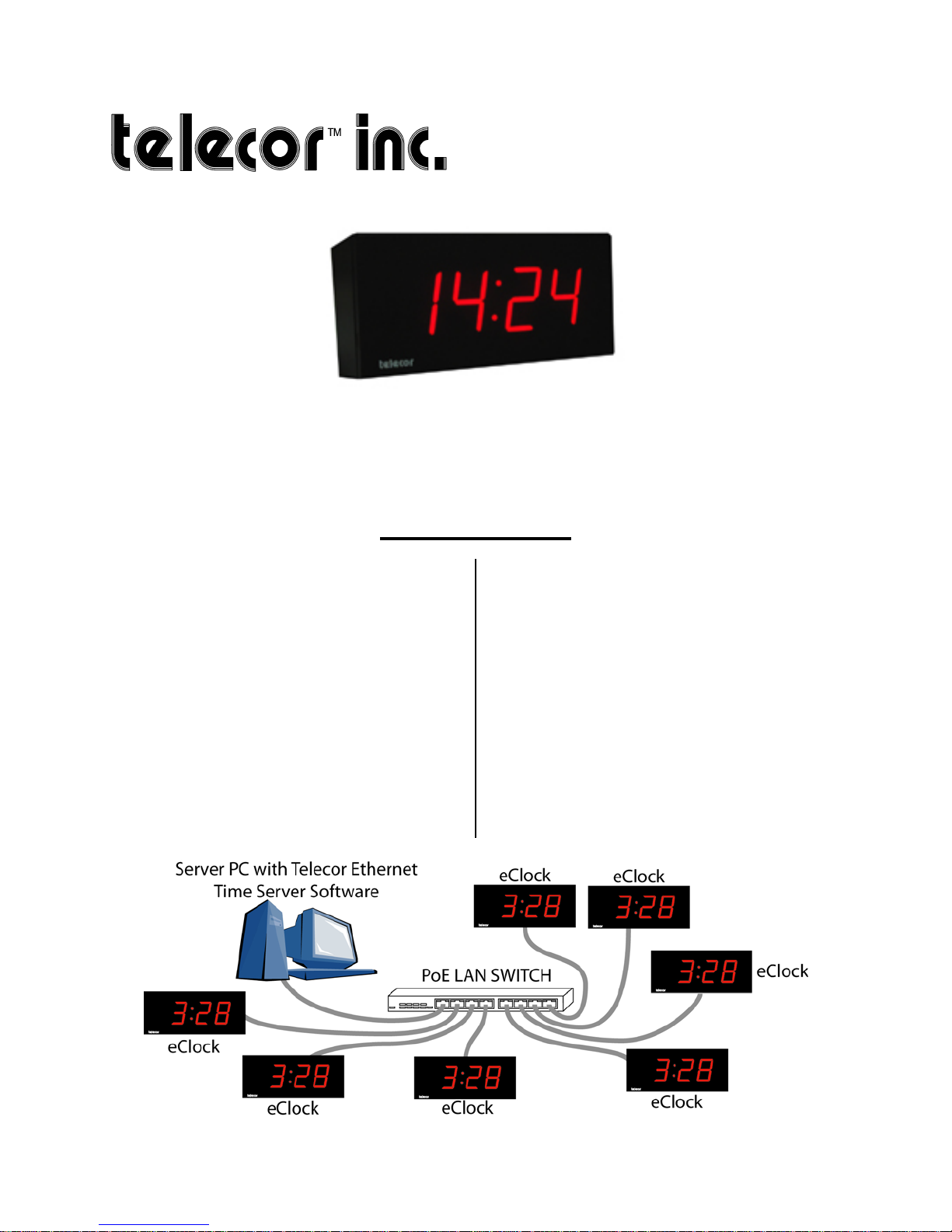
This document provides instructions for the
quick installation and operation of the
Telecor eClock. The eClock uses Powerover-Ethernet technology to draw both
power and data from a local area network
(LAN). This allows for an eClock network
to be easily and quickly installed in a
facility. The eClock receives its clock data
from a computer on the same network that is
running the Telecor Ethernet Time Server
Software. If an eClock loses its connection
to this computer or the LAN, it will
independently keep the time. The eClock
will resynchronize with the Time Server
once the connection is re-established.
eClocks are available in 2" and 4" models
This document is organized into the
following topics:
A. Introduction
B. Software Installation
C. eClock Installation
Appendix 1 – Backbox Dimensions
D.
E.
Appendix 2 – CAT5 Wiring
Appendix 3 - Troubleshooting
F.
Introduction 1
Page 2
B. Software Installation
The Telecor Ethernet Time Server Software
must be installed on a computer connected
to the same LAN as the eClocks.
Note: The Telecor Ethernet Time Server
Software is only supported on Microsoft
Windows 7 64-bit Professional,
Enterprise, and Ultimate editions.
1
Follow the instructions below to install the
Telecor Ethernet Time Server Software:
1. Use your Internet browser to go to
the MyTelecor website at
http://www.mytelecor.com.
2. At the main menu, click the Web
Store option.
3. From the left column, click on the
eClocks option.
4. From the list of displayed products,
click on the SW-ETS item.
8. Using Windows Explorer, navigate
to the folder where the file was
downloaded to. Double-click the file
to open the ZIP file. Copy the
contents of the ZIP file to a
temporary folder.
9. Using Windows Explorer, navigate
to the folder where the contents of
the ZIP file were copied to. Double
click on Setup.exe to run the
installation program.
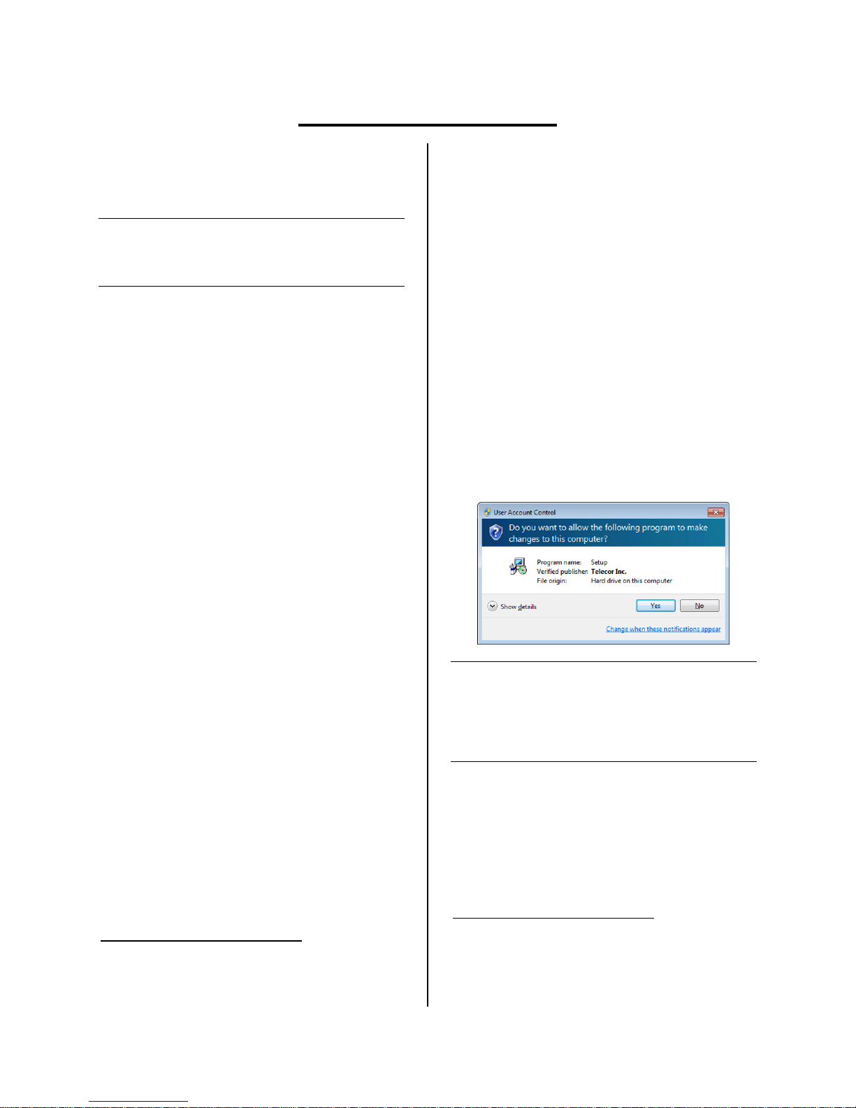
10. You may see a User Account Control
message asking to allow a program
published by Telecor Inc. to make
changes to your computer. Click
Yes.
5. At the Time Server Software page,
scroll down to the related documents
section and click on the Telecor
Ethernet Time Server Software
link.
6. The Telecor Ethernet Time Server
Software will have a suffix
indicating its version. E.g., Telecor
Ethernet Time Server Software V1.0
GR1.
7. When prompted by your Internet
browser, save the file to a temporary
folder. E.g., C:\TEMP\
1
Telecor tests the installation of its software products on the
U.S. English version of Microsoft operating systems. Other
regional or languages versions of Microsoft operating
systems may not fully support Telecor software.
Note: If the User Account Control message
states that the program publisher is
unknown, you need to update your
computer's certificate store. Go to
https://www.startcom.org using
Microsoft Internet Explorer.
2
Be sure to note the https in the URL. Certificates are
automatically updated when the website is visited.
Microsoft Internet Explorer must be used to view the
website. Any other web browser cannot be used to update
the certificate store.
2
2 Software Installation
Page 3
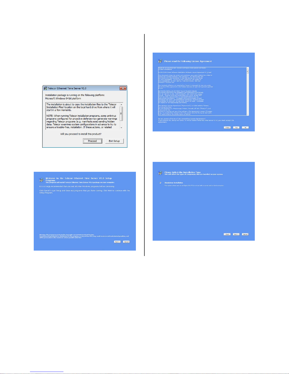
11. A window will appear explaining
that the installation procedure may
generate antivirus warnings. Telecor
confirms that that it is safe to
proceed with the installation despite
these antivirus warnings. Click
Proceed.
12. A welcome screen will appear. Click
Next.
13. Read the terms of the License
Agreement and then click Yes.
14. When prompted to select the
installation type, choose Standalone
Installation, and then click Next.
Software Installation 3
Page 4

15. A summary of software components
to be installed will appear. Click
Next.
16. When prompted to enter registration
information for the Telecor Ethernet
Time Server Software, enter the
registration information you received
with your Telecor Ethernet Time
Server Software package. Then click
Next.
17. Wait for the software to finish
installing.
18. When the installation is finished,
click Reboot to reboot your
computer. If you need to complete
other tasks on the computer, click
Exit. Reboot your computer once
you are ready to do so.
4 Software Installation
Now that the Telecor Ethernet Time Server
Software has been successfully installed,
you are ready to install the eClocks.
Page 5
C. eClock Installation
Materials required:
Flush backbox (2421-BBF for 2.5", 2431-BBF for 4") (purchased separately) or
Surface backbox (2421-BBS for 2.5", 2431-BBS for 4") (purchased separately)
Four backbox mounting screws (and anchors for surface mount backbox) appropriate for
wall surface (not provided)
Four #8 x 1" screws (provided)
One #4 x 5/8" self-tap locking screw (provided, used with 2431-BBF or 2431-BBS)
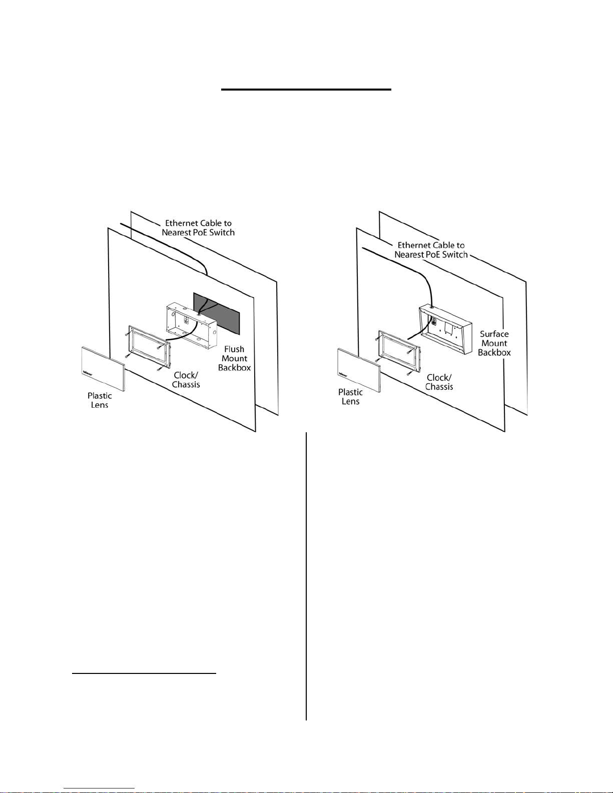
1. Install a flush or surface mount
backbox to the wall where the
eClock will be installed.1
a. Install Flush Backbox (2421-BBF or
2431-BBF)
i. Ensure the recessed portion of
the wall is the appropriate size
for the flush backbox. Refer to
Appendix 1 – Backbox
Dimensions.
ii. Punch out the appropriate
knockout on the backbox for
desired cable entry.
iii. Secure the backbox within the
wall using four screws.
1
CAT5 Ethernet cables have a maximum effective length of
328 ft (100m). Ensure that the eClock will not be located at a
distance from the PoE network switch that requires a cable
length greater than 328 ft.
b. Install Surface Backbox (2421-BBS
or 2431-BBS)
i. Ensure there is ample space on
the wall surface for the surface
backbox. Refer to
Appendix 1 –
Backbox Dimensions.
ii. Punch out the appropriate
knockout on the backbox for
desired cable entry.
iii. Place the backbox onto the wall
surface and mark the four
mounting screw locations.
iv. Install anchors at the four mark
locations
v. Secure the backbox to the
anchors/wall using four screws.
eClock Installation 5
Page 6

2. Pull a CAT5 Ethernet cable through
the knockout of the backbox.
3. Terminate the end of the CAT5
Ethernet cable pulled through the
backbox. The cable must be
terminated according to T568B
wiring specifications. Refer to
Appendix 2 – CAT5 Wiring.1
4. Remove the red plastic lens from the
eClock chassis by inserting a
flathead screwdriver into the tabs on
the side of the lines. Carefully twist
the screwdriver to snap each tab out
of the clock chassis. 4" eClocks have
a #4 x 5/8" self-tap locking screw on
the top or bottom edge of the lens
that must be removed before
removing the releasing the tabs.
5. Plug the CAT5 Ethernet cable to the
eClock Ethernet port.
7. Replace the plastic lens over the
eClock chassis and snap it into place.
Ensure that the paper framing insert
is inside the lens. For 4" eClocks,
secure the lens to the clock chassis
using the #4 x 5/8" self-tap locking
screw.
8. Terminate the other end of the CAT5
Ethernet cable. The cable must be
terminated according to T568B
wiring specifications. Refer to
Appendix 2 – CAT5 Wiring. Plug the
cable to the PoE network switch. The
eClock will power up, perform a
display testing sequence, and then
display the time.2
9. Repeat steps 1 through 8 for each
eClock in the facility.
6. Carefully mount the eClock onto the
installed backbox using the four #8 x
1" screws.
1
After terminating the CAT5 Ethernet cable, ensure that it is
wired properly by using a RJ45 cable tester before
connecting the cable to the eClock and PoE network switch.
If desired, the CAT5 Ethernet cable can be terminated using
a toolless keystone jack inside the backbox for easier wiring.
Refer to Appendix 2 – CAT5 Wiring.
If the CAT5 Ethernet cable running outside the backbox is
exposed, steps should be taken to protect the cable using
cable raceways or conduits. Refer to Appendix 2 – CAT5
Wiring.
2
The PoE network switch must be able to support maximum
power for each eClock connected to it. Each port on the
switch must support IEEE 802.3af with a maximum power of
15.4W (12.95W at the eClock).
6 eClock Installation
Page 7
D. Appendix 1 – Backbox Dimensions
The dimensions of the backboxes available for eClock flush or surface mounting are as follows:
Model eClock Display Size Mounting Type Dimensions (inches)
2421-BBF 2.5" Flush 10.75W x 4.5H x 3.75D
2421-BBS 2.5" Surface 10.75W x 4.5H x 3.75D
2431-BBF 4" Flush 14.25W x 7.25H x 3.75D
2431-BBS 4" Surface 14.25W x 7.25H x 3.75D
E. Appendix 2 – CAT5 Wiring
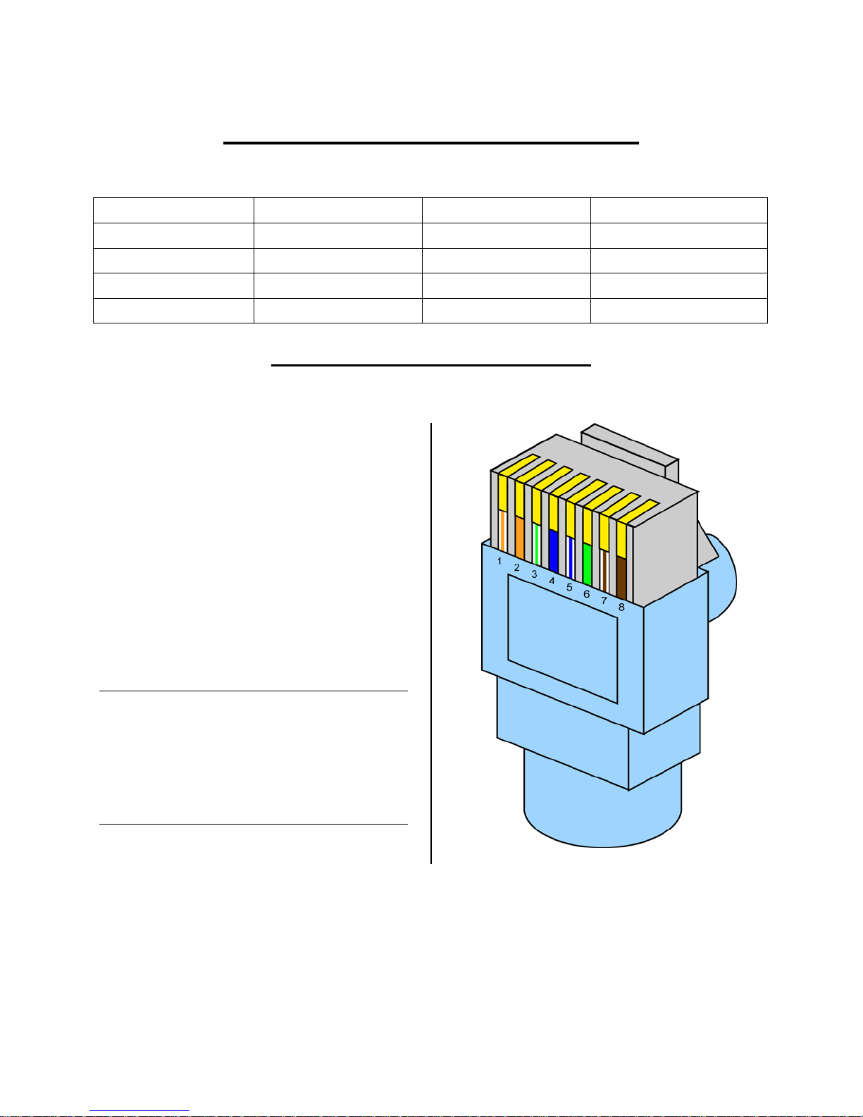
E.1 T568B Wiring Specifications
The Ethernet cables used to wire the
eClocks must be wired according to the
T568B wiring specification. The T568B
wiring specification is as follows:
1.White/orange stripe
2. Solid orange
3. White/green stripe
4. Solid blue
5. White/blue stripe
6. Solid green
7. White/brown stripe
8. Solid brown
Note: The following diagram shows the T568B
wiring specification in a common RJ45
plug. Manufacturers of toolless RJ45
plugs and (toolless and non-toolless)
RJ45 keystone jacks may include
specific instructions on how to wire their
products according to T568B
specification.
Appendices 7
Page 8
E.2 Terminating CAT5 Ethernet Cable
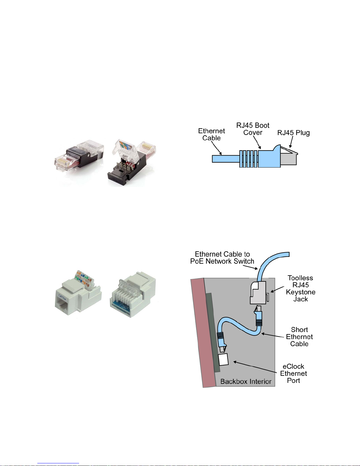
The Ethernet cable used to wire the eClocks
must be terminated using RJ45 boot covers
(to prevent cable pinching and snagging)
and RJ45 plugs to ensure connection
compatibility and quality.
Telecor recommends the use of toolless
As the directions for the installation of RJ45
boot covers and RJ45 plugs vary by
manufacturer, refer to the installation
instructions provided by your RJ45 boot
cover and RJ45 plug manufacturer.
RJ45 plugs for ease of installation without
the use of a crimping tool.
E.3 Terminating CAT5 Ethernet Cable with Toolless RJ45 Keystone
Jack
Alternatively, you can terminate the
Ethernet cable originating from the PoE
network switch using a toolless RJ45
keystone jack for ease of installation without
the use of a punch down tool.
The final connection between the eClock
Ethernet port and the toolless RJ45 keystone
jack can then be made with a short (6") store
bought, pre-terminated CAT5 Ethernet
cable.
As the directions for the installation of
toolless RJ45 keystone jacks vary by
manufacturer, refer to the installation
instructions provided by your toolless RJ45
keystone jack manufacturer.
8 Appendices
Page 9
E.4 Protecting CAT5 Ethernet Cables
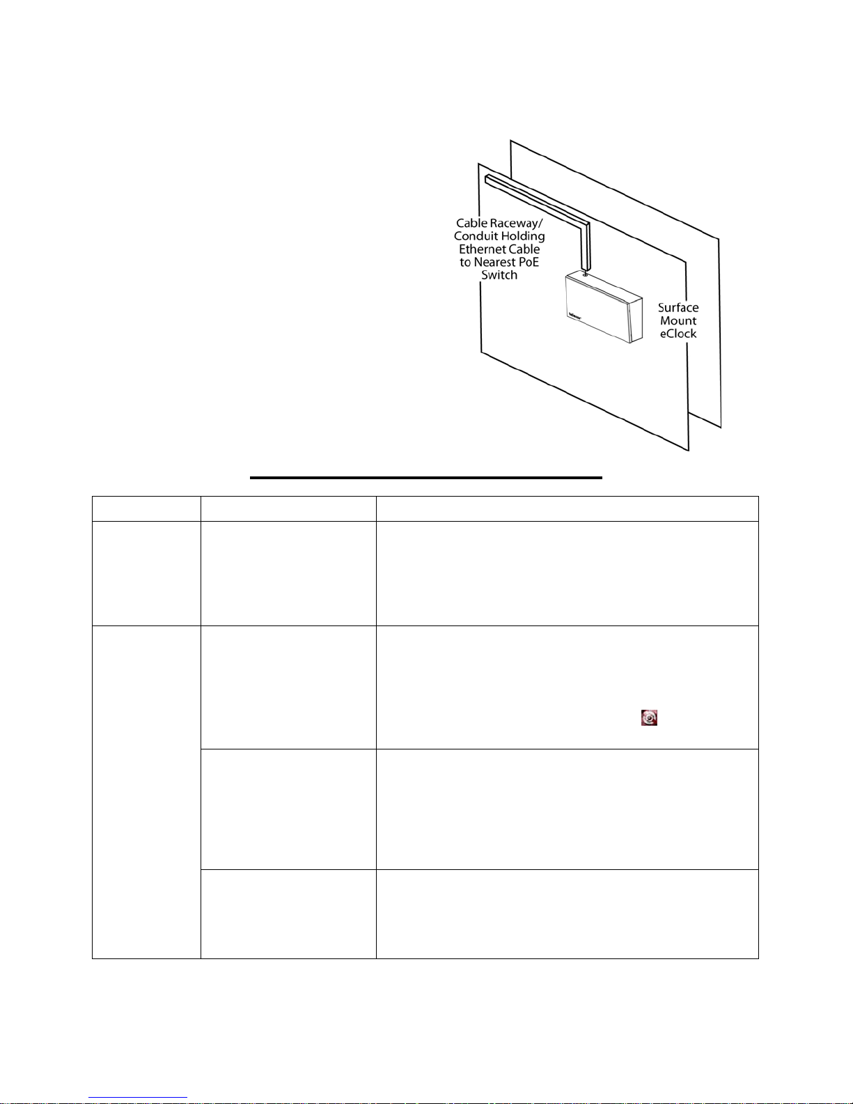
Steps should be taken to organize and
protect any portions of the CAT5 Ethernet
cables beyond the eClock backbox that are
exposed, e.g., lengths of cable connected to
the eClock that hang loosely.
Telecor recommends that cable raceways or
conduits are used to protect any lengthy
portions of exposed cabling.
As the directions for the installation of cable
raceways or conduits vary by manufacturer,
refer to the installation instructions provided
by your cable raceway or conduit
manufacturer.
F. Appendix 3 - Troubleshooting
Symptom Possible Cause Recommended Solutions
eClock
displays
incorrect time.
The colon ( : )
on the eClock
display is
blinking at a
rapid rate of ⅓
second on-⅔
second off.
The Server PC running
the Telecor Ethernet
Time Server Software
and connected to the
eClock network is set to
an incorrect time.
The Server PC running
the Telecor Ethernet
Time Server Software
has been shut down or
the Telecor Ethernet
Time Server Software is
not running.
The network the eClock
and the Server PC
running the Telecor
Ethernet Time Server
Software is not a single
local area network (LAN).
There is a connection
issue with the LAN.
The Server PC running the Telecor Ethernet Time Server
Software must have the correct time in order for the
eClocks to display the correct time. Ensure that the Server
PC has the correct time and is updated correctly for
Daylight Savings Time.
If the Server PC has been turned off, turn the PC back on.
If the Telecor Ethernet Time Server Software is not
running, the icon in the system tray will not display a green
checkmark. To turn on the Telecor Ethernet Time Server
Software, right-click the system tray icon (
Turn On from the list.
The Server PC running the Telecor Ethernet Time Server
Software must be on the same local area network (LAN) as
the eClock. A single, continuous LAN-based connection is
required between the Server PC and the eClock. The
eClock cannot communicate with the Server PC through a
wide area network (WAN) or Internet-based network.
Contact your network administrator for support.
Ensure that all CAT5 Ethernet cable connections between
the eClock and the Server PC running the Telecor Ethernet
Time Server Software are connected and working properly.
If the problem persists, contact your network administrator
for support.
) and select
© Copyright 2013 by Telecor Inc. All rights reserved. No part of this publication may be reproduced in any form or by any means without the prior written permission of Telecor
Inc. Telecor Inc. makes no representation of warranties with respect to this manual. Furthermore, Telecor reserves the right to make changes in the specifications of the product
described in this manual anytime without notice and without obligation of Telecor to notify any person of such revisions or changes.
Appendices 9
E:\T3-112\QuickStart\T3-M112-B.doc
 Loading...