

Teleconnect Socrates Series, SHDSL.EVB.4CH User Manual

Teleconnect GmbH
Am Lehmberg 54
01157 Dresden/Germany
© 2019 Teleconnect GmbH
SOCRATES Series
SHDSL.EVB.4CH
User Manual
Revision: 1.0.0, 2019-02-05

SHDSL.EVB.4CH User Manual
Revision: 1.0.0, 2019-02-05 2/37 shdsl@teleconnect.de
Revision History:
Current Revision: 1.0.0, 2019-02-05
Revision
Date
Comment
1.0.0
2019-02-05
Initial release

SHDSL.EVB.4CH User Manual
Revision: 1.0.0, 2019-02-05 3/37 shdsl@teleconnect.de
Table of Contents
1 Introduction .................................................................................................................... 5
1.1 Scope of this Document .......................................................................................... 5
1.2 General Introduction ................................................................................................ 5
1.3 Content of the SHDSL.EVB.4CH Evaluation Board Kit ............................................ 6
2 Block Diagram ................................................................................................................ 7
3 Interfaces ....................................................................................................................... 9
3.1 Design Overview ..................................................................................................... 9
3.2 SHDSL Interface ..................................................................................................... 9
3.3 Ethernet Interface via PHY .....................................................................................12
3.4 Ethernet Interface via Switch ..................................................................................14
3.5 Power Supply Input ................................................................................................14
3.6 Power Consumption ...............................................................................................15
3.7 Serial Interface (UART) ..........................................................................................15
3.8 Debug interface ......................................................................................................16
3.9 Control and Monitoring Interface ............................................................................16
3.9.1 Buttons ............................................................................................................16
3.9.2 DIP switches ...................................................................................................17
3.9.3 Rotary switch (10 pole) ....................................................................................18
3.9.4 Rotary switch (16 pole) ....................................................................................18
3.9.5 LEDs ...............................................................................................................18
4 Software ........................................................................................................................20
4.1 Updating Firmware .................................................................................................20
4.1.1 Preparation .....................................................................................................20
4.1.2 Using the in-system programmer ....................................................................20
4.2 SHDSL.EVB.4CH Firmware 3.0 .............................................................................22
4.3 Functions and packages ........................................................................................23
5 User Interfaces ..............................................................................................................24
5.1 Establish a Connection ...........................................................................................24
5.2 BSI - Basic Status/SHDSL Interface .......................................................................24
5.3 CLI - Command Line Interface ...............................................................................26
5.3.1 Login ...............................................................................................................26
5.3.2 CLI commands ................................................................................................27
5.3.3 Password modification ....................................................................................28
5.3.4 Configuring the system ....................................................................................29
5.3.5 Firmware update .............................................................................................30
6 Operation ......................................................................................................................33
6.1 Start-up with two boards .........................................................................................33
7 Using SHDSL.EVB.4CH as Module ...............................................................................34
7.1 Scope .....................................................................................................................34
7.2 Connection .............................................................................................................34
7.3 Protection ...............................................................................................................34
8 Literature .......................................................................................................................35
Appendix A. Quick Start-up guide ....................................................................................36

SHDSL.EVB.4CH User Manual
Revision: 1.0.0, 2019-02-05 4/37 shdsl@teleconnect.de
List of Figures
Figure 1: Structure of SHDSL Link ......................................................................................... 5
Figure 2: Main components of SHDSL.EVB.4CH Evaluation Board ....................................... 6
Figure 3: Block Diagram of the SHDSL.EVB.4CH Evaluation Board....................................... 7
Figure 4: Functions of the SHDSL.EVB.4CH Evaluation Board .............................................. 9
Figure 5: SHDSL Interface ..................................................................................................... 9
Figure 6: (Extract from) Schematic of SHDSL Hybrid ........................................................... 11
Figure 7: Ethernet interface .................................................................................................. 12
Figure 8: Schematic of Ethernet Interface via PHY ................................ ............................... 13
Figure 9: Schematic of Ethernet Interface via Switch ............................................................ 14
Figure 10: SAM-BA menu: select connection and board ....................................................... 21
Figure 11: SAM-BA menu: select firmware image and download them ................................. 21
Figure 12: SAM-BA menu: press execute ............................................................................. 22
Figure 13: CLI menu tree ...................................................................................................... 27
Figure 14: CLI example: config/show ? ................................................................................. 28
Figure 15: CLI example: password modification ................................................................... 28
Figure 16: CLI example for show modified SHDSL configuration ................................ .......... 29
Figure 17: CLI example for net configuration ........................................................................ 30
Figure 18: CLI example for show stored firmware list ........................................................... 31
SHDSL.EVB.4CH User Manual
Revision: 1.0.0, 2019-02-05 5/37 shdsl@teleconnect.de
1 Introduction
1.1 Scope of this Document
This document describes the hardware and software to get started with the SHDSL 4-Channel
Evaluation Board from the Teleconnect SOCRATES series. The product code
“SHDSL.EVB.4CH” used for this document.
Teleconnect (http://www.teleconnect.de/xdsl/socrates-evb) provides all necessary
documentations for recreating of the hardware. This includes schematic, components layout
placement, board outline, PCB layout, bill of materials and available software features. Gerber
files are available upon request at shdsl@teleconnect.de.
1.2 General Introduction
The new SHDSL.EVB.4CH reference design targeting industrial designs enables customers
to take advantage of Intel® SHDSL Chipset (previously known as "Lantiq SOCRATES™-4E")
for long reach broadband connectivity. It is the first ever ready-to-copy reference design
developed for the Intel® SHDSL Chipsets. The SHDSL/Ethernet Bridge Modem was developed
by Teleconnect and measures only about 11 x 12,5 cm. It is available for online purchase
through:
• Würth Elektronik webshop (http://www.we-online.com/socratesdemo).
Teleconnect offers dedicated support for board and software customizations. With this
Evaluation Board you get an Evaluation License for the Software Packages P1-P2-P3-P4-P5P6-P8-PD including bootloader and firmware update. For more information please see chapter
4.3 Functions and packages. With this, for the first time ever, even smaller companies without
DSL expertise can include SHDSL and Long-Reach-Ethernet connectivity into their designs.
SHDSL’s unique rate/reach performance makes it the product of choice in an ever more
diversified field of applications ranging from business broadband access to enterprise networks
and industrial communications.
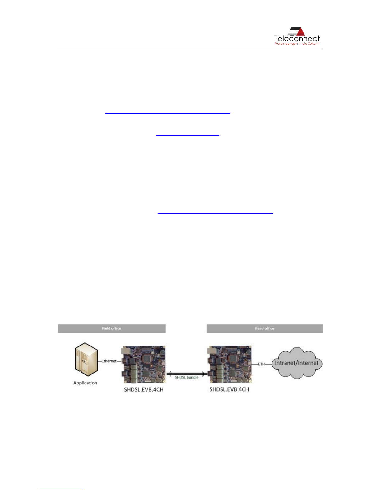
Known as long haul Ethernet, SHDSL was included in the Ethernet standard IEEE 802.3-2008
[1], where it is named 2BASE-TL. Standard Ethernet has a maximum reach of 100 m. SHDSL
has a reach beyond 15 kilometers.
Using SHDSL enables costumer to transmit Ethernet over only one unshielded twisted wire
pair or over any other cable. An example structure of SHDSL is shown at Figure 1.
Figure 1: Structure of SHDSL Link
SHDSL.EVB.4CH User Manual
Revision: 1.0.0, 2019-02-05 6/37 shdsl@teleconnect.de
1.3 Content of the SHDSL.EVB.4CH Evaluation Board Kit
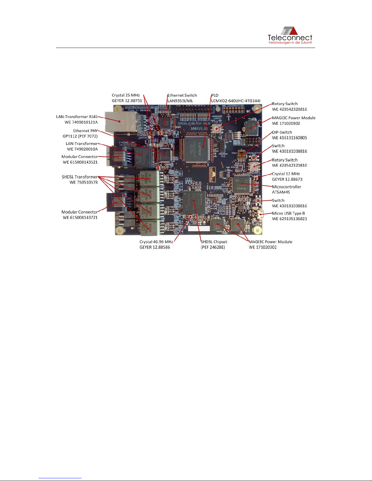
The evaluation kit contains the SHDSL.EVB.4CH Evaluation Board shown in Figure 2. Beside
this you need a power source provided via short and high quality micro USB cable. For
Ethernet and SHDSL connection, standard Ethernet patch cables can be used.
Figure 2: Main components of SHDSL.EVB.4CH Evaluation Board
Please consider the changes for the chip manufacturers (Lantiq was acquired by Intel®). In the
past, the SHDSL transceiver PEF 24628 E was offered by Lantiq as SOCRATES™-4E with
identical PEF number. Now the SHDSL chipset is offered by Intel® as Intel® SHDSL Chipset.
This also applies to the Ethernet PHY. In the past, the XWAY™ PHY11G was offered by Lantiq,
now the chip is called Intel® Ethernet Network Connection GPY112 and offered by Intel®.
In 2016, Microchip agreed to buy Atmel®. That´s the reason why the Atmel® microcontroller
ATSAM4S is now part of Microchip product spectrum.
SHDSL.EVB.4CH User Manual
Revision: 1.0.0, 2019-02-05 7/37 shdsl@teleconnect.de
2 Block Diagram
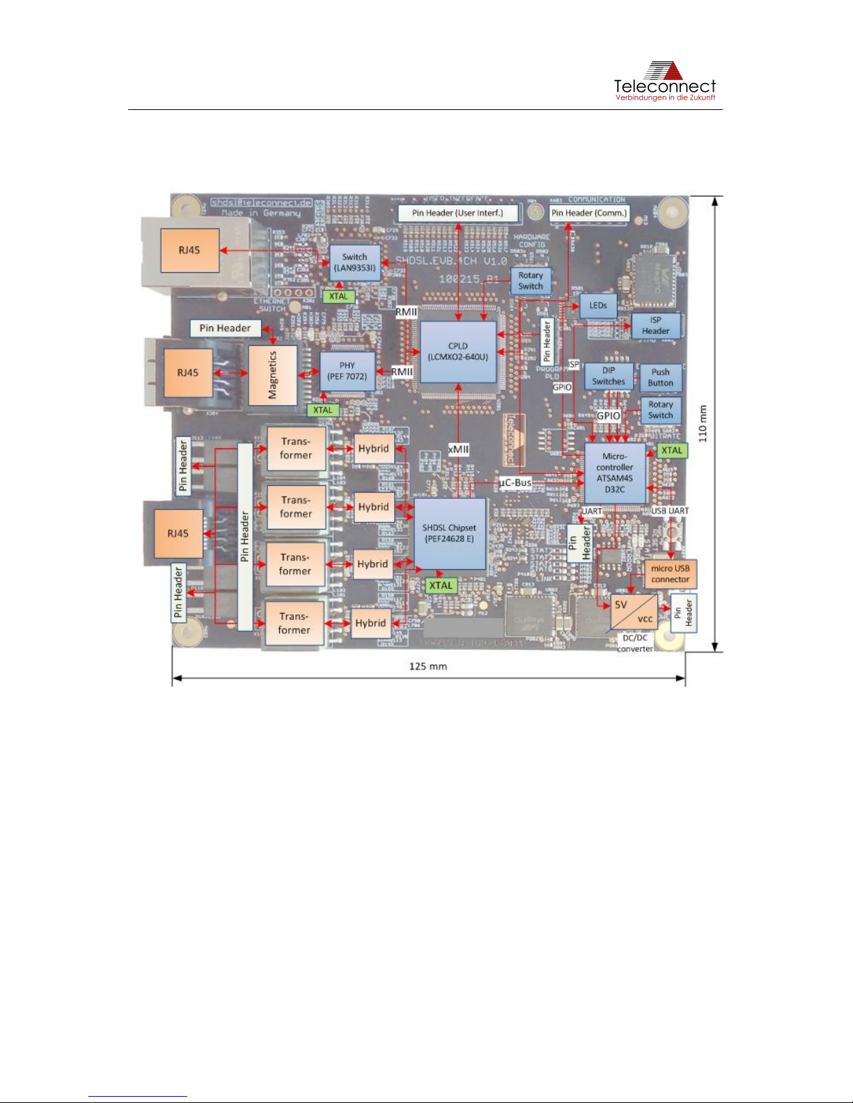
Figure 3 shows the block diagram of the SHDSL.EVB.4CH Evaluation Board.
Figure 3: Block Diagram of the SHDSL.EVB.4CH Evaluation Board
The SHDSL.EVB.4CH Evaluation Board consists of the following blocks:
• SHDSL transceiver Intel® SHDSL Chipset (PEF 24628 E) (previously known as "Lantiq
SOCRATES-4E" with same PEF number).
The functionality of the Evaluation Board could also be realized with the 1ch versions
of the Intel® SHDSL Chipsets (PEF 21628 E). Teleconnect provides 1ch SHDSL
Evaluation Board also (product code: SHDSL.1CH.EVB [2]).
You can use one up to four channels with SHDSL.EVB.4CH.
• Intel® Ethernet Network Connection GPY112 (PEF 7072), Version 1.6 (previously
known as "Lantiq PHY11G").
The GPY112 is a Gigabit Ethernet PHY. However, in this application only
10/100BaseTX is available.
• Ethernet switch LAN9353 is prepared for future use cases. It cannot be used at the
current development stage.
• CPLD LCMXO2-640U is for the adaption between PHY interface, Switch interface and
SHDSL chipset.

SHDSL.EVB.4CH User Manual
Revision: 1.0.0, 2019-02-05 8/37 shdsl@teleconnect.de
• Microcontroller Microchip ATSAM4SD32C (previously known as "Atmel
ATSAM4SD32C").
The microcontroller is used for configuration, controlling and monitoring. The
requirements of the microcontroller are very low, e.g. an 8-bit controller has enough
performance for SHDSL. We use the ARM® based microcontroller to provide a highly
flexible evaluation platform.
• RJ45 connectors (shielded for Ethernet and unshielded for SHDSL), both from Würth
Elektronik eiSos GmbH
• Micro USB connector Type B (Würth Elektronik eiSos GmbH),
• SHDSL Hybrid including SHDSL transformer (Würth Elektronik eiSos GmbH),
• Ethernet magnetics (Würth Elektronik eiSos GmbH),
• DC/DC converter from 5 V to 3.3 V, 1.5 V and 1.0 V. Three voltage regulators from
MPS (Mini-Module Family) are used.
• XTAL for SHDSL-transceiver, Ethernet-PHY and Microcontroller (Geyer Electronic),
• Input and Output components (Würth Elektronik eiSos GmbH):
o two Rotary switches and one DIP switch 5 pole,
o two Push buttons,
o ISP pin header for debugging of the microcontroller,
o nine LEDs.
SHDSL.EVB.4CH User Manual
Revision: 1.0.0, 2019-02-05 9/37 shdsl@teleconnect.de
3 Interfaces
This chapter describes the interfaces and header pinouts of the SHDSL.EVB.4CH Evaluation
Board.
3.1 Design Overview
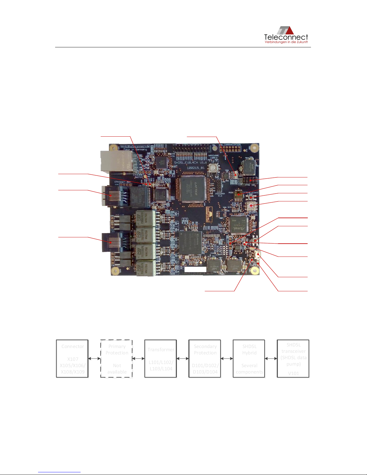
The design with its main function blocks and important components are shown in Figure 4. The
description for it is given in the following section.
Figure 4: Functions of the SHDSL.EVB.4CH Evaluation Board
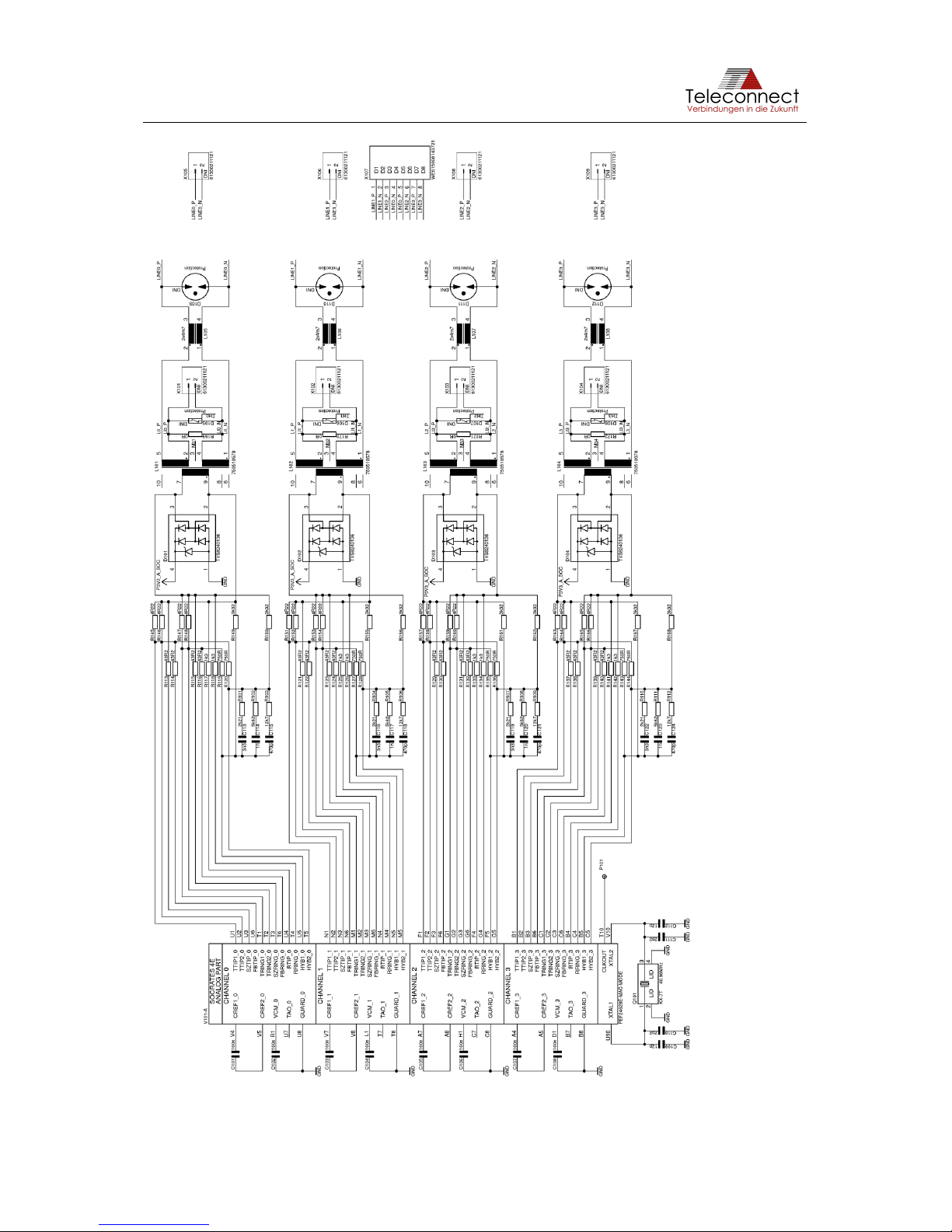
3.2 SHDSL Interface
The SHDSL interface is divided in SHDSL connector, SHDSL Transformer, Protection, Hybrid
and SHDSL data pump (see Figure 5).
Figure 5: SHDSL Interface
Additional primary protection is necessary depending on requirements. There is no primary
protection on the evaluation board available.
The connector X107 is an unshielded RJ45 connector. It is used for connecting the
SHDSL.EVB.4CH up to four SHDSL lines (according ITU-T G.991.2 [3]). Table 1 shows the
pin definition of X107.
Erase Button
Micro USB:
Power and UART
emulation
Reset Button
Alternative
Power: +5,0V
Alternative
UART
JTAG:
Connection to
AVR debugger/
programmer
Select Mode
Select Bitrate
Ethernet
Connector
SHDSL
Connector
Green LED:
Ethernet Link/
Activity
Amber LED:
Ethernet Error
detected
Green LEDs:
SHDSL line states
(connection established, Training, Idle)
Green LED:
Power
Amber LED:
Status
Red LED:
Error
SHDSL
transceiver
(SHDSL data
pump)
V101
SHDSL
Hybrid
Several
components
Secondary
Protection
D101/D102/
D103/D104
Transformer
L101/L102/
L103/L104
Primary
Protection
Not
available
Connector
X107
X105/X106/
X108/X109
SHDSL.EVB.4CH User Manual
Revision: 1.0.0, 2019-02-05 10/37 shdsl@teleconnect.de
Table 1: Pin Definition of X107
Pin Number
Pin Name / Function
1
SHDSL line #2 – Ring
2
SHDSL line #2 – Tip
3
SHDSL line #3 – Ring
4
SHDSL line #1 – Tip
5
SHDSL line #1 – Ring
6
SHDSL line #3 – Tip
7
SHDSL line #4 – Ring
6
SHDSL line #4 – Tip
Typical lines are unshielded twisted pair cables. Any standard Ethernet cable is also usable.
Beside the RJ45 connector X107 SHDSL.EVB.4CH provides the possibility to use the pin
header X105 (SHDSL line #1), X106 (SHDSL line #2), X108 (SHDSL line #3) and X109
(SHDSL line #4) spaced 2.54 millimeters (0.1 in). Table 2 gives the pin definition.
Table 2: Pin Definition of X105, X106, X108 and X109
Pin Number
Pin Name / Function
1
SHDSL line #X – Tip (X = 1...4)
2
SHDSL line #X – Ring (X = 1...4)
The pin header X105 (SHDSL line #1), X106 (SHDSL line #2), X108 (SHDSL line #3) and
X109 (SHDSL line #4) are not mounted by default. It is possible to mount it on both PCB sides
to get an easy test adapter for evaluation or to use the SHDSL.EVB.4CH as a module.
Figure 6 shows the schematic of the SHDSL hybrid with line transformer L101, L102, L103
and L104 and SHDSL data pump V101 (PEF 24628 E).
Components and layout are influencing the SHDSL performance. Teleconnect can assist you
with the selection of additional line protection at raw ambient conditions.
SHDSL.EVB.4CH User Manual
Revision: 1.0.0, 2019-02-05 11/37 shdsl@teleconnect.de
Figure 6: (Extract from) Schematic of SHDSL Hybrid
SHDSL.EVB.4CH User Manual
Revision: 1.0.0, 2019-02-05 12/37 shdsl@teleconnect.de
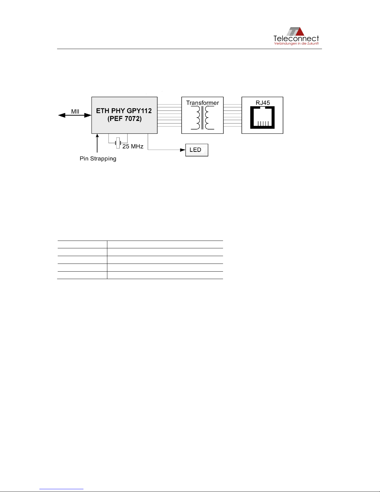
3.3 Ethernet Interface via PHY
The useable Ethernet interface via PHY is divided in connector, transformer (magnetics) and
Ethernet PHY (see Figure 7).
Figure 7: Ethernet interface
The shielded RJ45 connector X304 is a standard Ethernet interface. It is compatible with
10BASE-T and 100BASE-TX Ethernet according to IEEE 802.3 [1] and can be connected to a
twisted pair medium such as CAT5 cable infrastructure.
Beside the RJ45 connector, SHDSL.EVB.4CH provides the possibility to use the pin header
X302 spaced 2.54 millimeters (0.1in). Table 3 gives the pin definition.
Table 3: Pin Definition of X302
Pin Number
Pin Name / Function
1
TX/RX1 +
2
TX/RX1 -
3
TX/RX2 +
4
TX/RX2 -
The pin header X302 is not mounted by default. It is possible to mount it on both PCB sides to
get an easy test adapter for evaluation or to use the SHDSL.EVB.4CH as module (see
chapter 7).
The transformer L302 connects the connector to the Ethernet PHY GPY112 V201 (PEF7072).
The connection to the SHDSL data pump Intel® SHDSL Chipset V101 is realized via standard
MII interface.
Figure 8 shows the schematic of the Ethernet interface via PHY.
 Loading...