

Page 1

Teleconnect GmbH
Am Lehmberg 54
01157 Dresden/Germany
© 2019 Teleconnect GmbH
SOCRATES Series
SHDSL.EVB.4CH
User Manual
Revision: 1.0.0, 2019-02-05
Page 2

SHDSL.EVB.4CH User Manual
Revision History:
Current Revision: 1.0.0, 2019-02-05
Revision
Date
Comment
1.0.0
2019-02-05
Initial release
Page 3

SHDSL.EVB.4CH User Manual
Table of Contents
1 Introduction .................................................................................................................... 5
1.1 Scope of this Document .......................................................................................... 5
1.2 General Introduction ................................................................................................ 5
1.3 Content of the SHDSL.EVB.4CH Evaluation Board Kit ............................................ 6
2 Block Diagram ................................................................................................................ 7
3 Interfaces ....................................................................................................................... 9
3.1 Design Overview ..................................................................................................... 9
3.2 SHDSL Interface ..................................................................................................... 9
3.3 Ethernet Interface via PHY .....................................................................................12
3.4 Ethernet Interface via Switch ..................................................................................14
3.5 Power Supply Input ................................................................................................14
3.6 Power Consumption ...............................................................................................15
3.7 Serial Interface (UART) ..........................................................................................15
3.8 Debug interface ......................................................................................................16
3.9 Control and Monitoring Interface ............................................................................16
3.9.1 Buttons ............................................................................................................16
3.9.2 DIP switches ...................................................................................................17
3.9.3 Rotary switch (10 pole) ....................................................................................18
3.9.4 Rotary switch (16 pole) ....................................................................................18
3.9.5 LEDs ...............................................................................................................18
4 Software ........................................................................................................................20
4.1 Updating Firmware .................................................................................................20
4.1.1 Preparation .....................................................................................................20
4.1.2 Using the in-system programmer ....................................................................20
4.2 SHDSL.EVB.4CH Firmware 3.0 .............................................................................22
4.3 Functions and packages ........................................................................................23
5 User Interfaces ..............................................................................................................24
5.1 Establish a Connection ...........................................................................................24
5.2 BSI - Basic Status/SHDSL Interface .......................................................................24
5.3 CLI - Command Line Interface ...............................................................................26
5.3.1 Login ...............................................................................................................26
5.3.2 CLI commands ................................................................................................27
5.3.3 Password modification ....................................................................................28
5.3.4 Configuring the system ....................................................................................29
5.3.5 Firmware update .............................................................................................30
6 Operation ......................................................................................................................33
6.1 Start-up with two boards .........................................................................................33
7 Using SHDSL.EVB.4CH as Module ...............................................................................34
7.1 Scope .....................................................................................................................34
7.2 Connection .............................................................................................................34
7.3 Protection ...............................................................................................................34
8 Literature .......................................................................................................................35
Appendix A. Quick Start-up guide ....................................................................................36
Page 4

SHDSL.EVB.4CH User Manual
List of Figures
Figure 1: Structure of SHDSL Link ......................................................................................... 5
Figure 2: Main components of SHDSL.EVB.4CH Evaluation Board ....................................... 6
Figure 3: Block Diagram of the SHDSL.EVB.4CH Evaluation Board....................................... 7
Figure 4: Functions of the SHDSL.EVB.4CH Evaluation Board .............................................. 9
Figure 5: SHDSL Interface ..................................................................................................... 9
Figure 6: (Extract from) Schematic of SHDSL Hybrid ........................................................... 11
Figure 7: Ethernet interface .................................................................................................. 12
Figure 8: Schematic of Ethernet Interface via PHY ................................ ............................... 13
Figure 9: Schematic of Ethernet Interface via Switch ............................................................ 14
Figure 10: SAM-BA menu: select connection and board ....................................................... 21
Figure 11: SAM-BA menu: select firmware image and download them ................................. 21
Figure 12: SAM-BA menu: press execute ............................................................................. 22
Figure 13: CLI menu tree ...................................................................................................... 27
Figure 14: CLI example: config/show ? ................................................................................. 28
Figure 15: CLI example: password modification ................................................................... 28
Figure 16: CLI example for show modified SHDSL configuration ................................ .......... 29
Figure 17: CLI example for net configuration ........................................................................ 30
Figure 18: CLI example for show stored firmware list ........................................................... 31
Page 5
SHDSL.EVB.4CH User Manual
1 Introduction
1.1 Scope of this Document
This document describes the hardware and software to get started with the SHDSL 4-Channel
Evaluation Board from the Teleconnect SOCRATES series. The product code
“SHDSL.EVB.4CH” used for this document.
Teleconnect (http://www.teleconnect.de/xdsl/socrates-evb) provides all necessary
documentations for recreating of the hardware. This includes schematic, components layout
placement, board outline, PCB layout, bill of materials and available software features. Gerber
files are available upon request at [email protected].
1.2 General Introduction
The new SHDSL.EVB.4CH reference design targeting industrial designs enables customers
to take advantage of Intel® SHDSL Chipset (previously known as "Lantiq SOCRATES™-4E")
for long reach broadband connectivity. It is the first ever ready-to-copy reference design
developed for the Intel® SHDSL Chipsets. The SHDSL/Ethernet Bridge Modem was developed
by Teleconnect and measures only about 11 x 12,5 cm. It is available for online purchase
through:
• Würth Elektronik webshop (http://www.we-online.com/socratesdemo).
Teleconnect offers dedicated support for board and software customizations. With this
Evaluation Board you get an Evaluation License for the Software Packages P1-P2-P3-P4-P5P6-P8-PD including bootloader and firmware update. For more information please see chapter
4.3 Functions and packages. With this, for the first time ever, even smaller companies without
DSL expertise can include SHDSL and Long-Reach-Ethernet connectivity into their designs.
SHDSL’s unique rate/reach performance makes it the product of choice in an ever more
diversified field of applications ranging from business broadband access to enterprise networks
and industrial communications.
Known as long haul Ethernet, SHDSL was included in the Ethernet standard IEEE 802.3-2008
[1], where it is named 2BASE-TL. Standard Ethernet has a maximum reach of 100 m. SHDSL
has a reach beyond 15 kilometers.
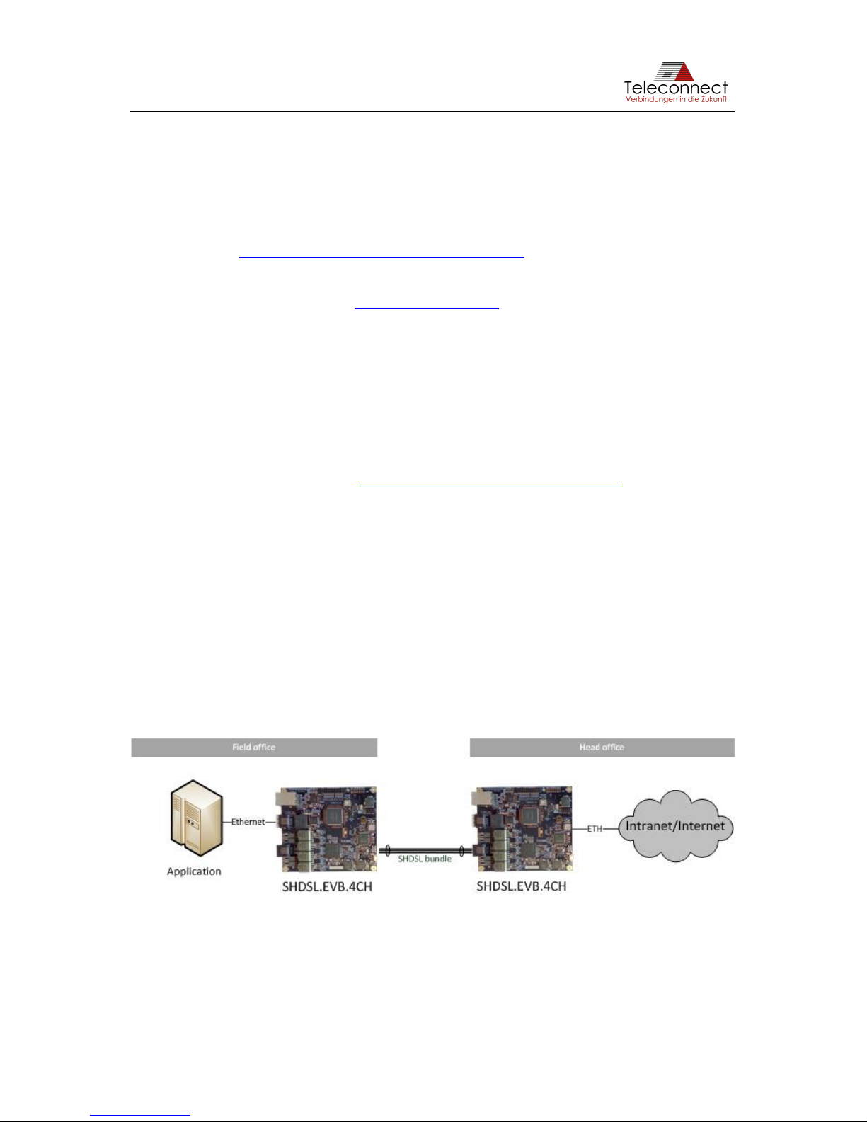
Using SHDSL enables costumer to transmit Ethernet over only one unshielded twisted wire
pair or over any other cable. An example structure of SHDSL is shown at Figure 1.
Figure 1: Structure of SHDSL Link
Page 6
SHDSL.EVB.4CH User Manual
1.3 Content of the SHDSL.EVB.4CH Evaluation Board Kit
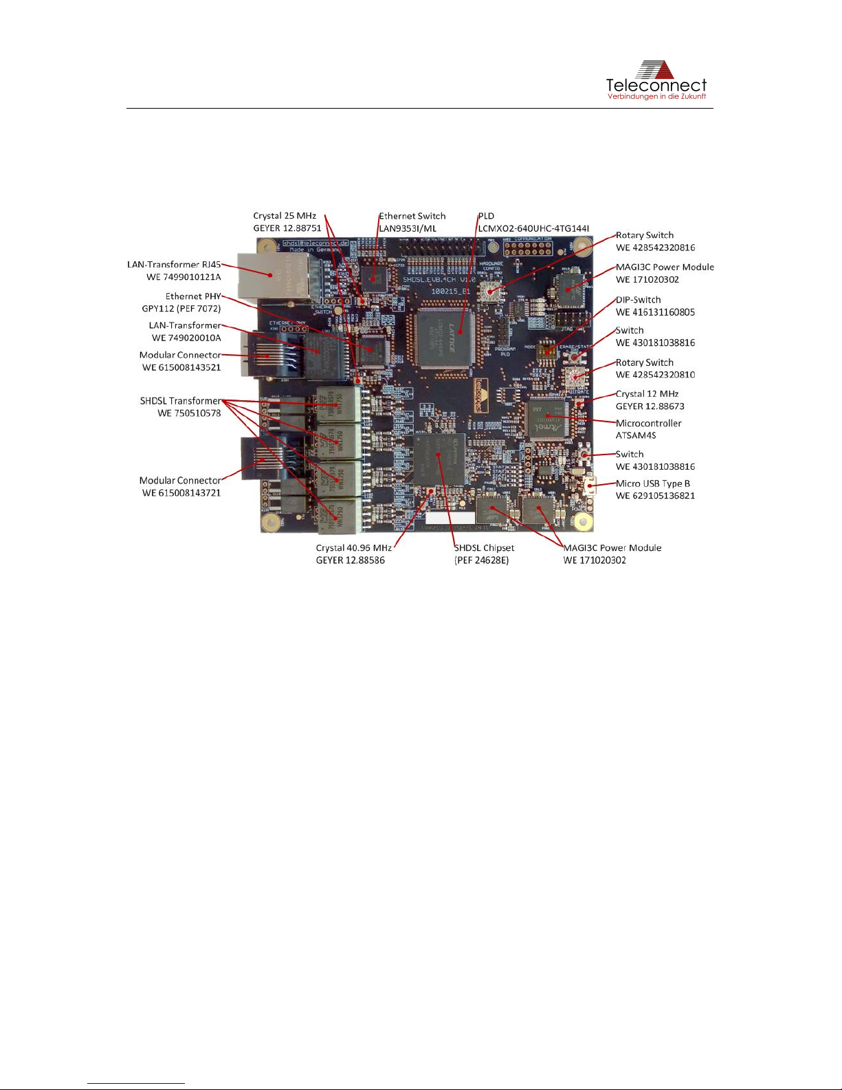
The evaluation kit contains the SHDSL.EVB.4CH Evaluation Board shown in Figure 2. Beside
this you need a power source provided via short and high quality micro USB cable. For
Ethernet and SHDSL connection, standard Ethernet patch cables can be used.
Figure 2: Main components of SHDSL.EVB.4CH Evaluation Board
Please consider the changes for the chip manufacturers (Lantiq was acquired by Intel®). In the
past, the SHDSL transceiver PEF 24628 E was offered by Lantiq as SOCRATES™-4E with
identical PEF number. Now the SHDSL chipset is offered by Intel® as Intel® SHDSL Chipset.
This also applies to the Ethernet PHY. In the past, the XWAY™ PHY11G was offered by Lantiq,
now the chip is called Intel® Ethernet Network Connection GPY112 and offered by Intel®.
In 2016, Microchip agreed to buy Atmel®. That´s the reason why the Atmel® microcontroller
ATSAM4S is now part of Microchip product spectrum.
Page 7
SHDSL.EVB.4CH User Manual
2 Block Diagram
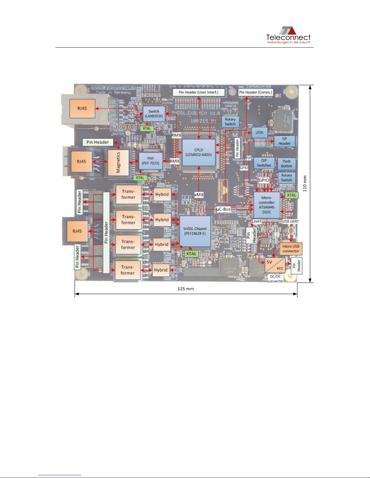
Figure 3 shows the block diagram of the SHDSL.EVB.4CH Evaluation Board.
Figure 3: Block Diagram of the SHDSL.EVB.4CH Evaluation Board
The SHDSL.EVB.4CH Evaluation Board consists of the following blocks:
• SHDSL transceiver Intel® SHDSL Chipset (PEF 24628 E) (previously known as "Lantiq
SOCRATES-4E" with same PEF number).
The functionality of the Evaluation Board could also be realized with the 1ch versions
of the Intel® SHDSL Chipsets (PEF 21628 E). Teleconnect provides 1ch SHDSL
Evaluation Board also (product code: SHDSL.1CH.EVB [2]).
You can use one up to four channels with SHDSL.EVB.4CH.
• Intel® Ethernet Network Connection GPY112 (PEF 7072), Version 1.6 (previously
known as "Lantiq PHY11G").
The GPY112 is a Gigabit Ethernet PHY. However, in this application only
10/100BaseTX is available.
• Ethernet switch LAN9353 is prepared for future use cases. It cannot be used at the
current development stage.
• CPLD LCMXO2-640U is for the adaption between PHY interface, Switch interface and
SHDSL chipset.
Page 8

SHDSL.EVB.4CH User Manual
• Microcontroller Microchip ATSAM4SD32C (previously known as "Atmel
ATSAM4SD32C").
The microcontroller is used for configuration, controlling and monitoring. The
requirements of the microcontroller are very low, e.g. an 8-bit controller has enough
performance for SHDSL. We use the ARM® based microcontroller to provide a highly
flexible evaluation platform.
• RJ45 connectors (shielded for Ethernet and unshielded for SHDSL), both from Würth
Elektronik eiSos GmbH
• Micro USB connector Type B (Würth Elektronik eiSos GmbH),
• SHDSL Hybrid including SHDSL transformer (Würth Elektronik eiSos GmbH),
• Ethernet magnetics (Würth Elektronik eiSos GmbH),
• DC/DC converter from 5 V to 3.3 V, 1.5 V and 1.0 V. Three voltage regulators from
MPS (Mini-Module Family) are used.
• XTAL for SHDSL-transceiver, Ethernet-PHY and Microcontroller (Geyer Electronic),
• Input and Output components (Würth Elektronik eiSos GmbH):
o two Rotary switches and one DIP switch 5 pole,
o two Push buttons,
o ISP pin header for debugging of the microcontroller,
o nine LEDs.
Page 9
SHDSL.EVB.4CH User Manual
3 Interfaces
This chapter describes the interfaces and header pinouts of the SHDSL.EVB.4CH Evaluation
Board.
3.1 Design Overview
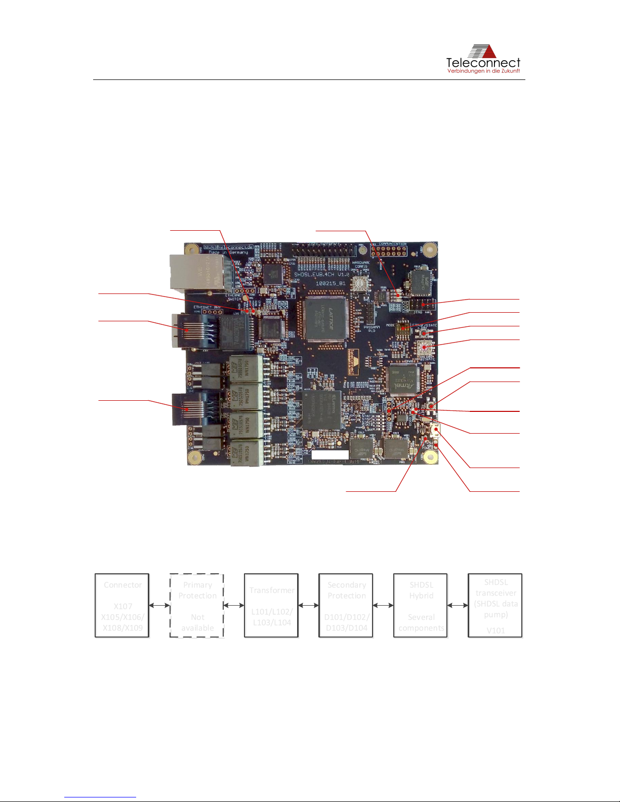
The design with its main function blocks and important components are shown in Figure 4. The
description for it is given in the following section.
Figure 4: Functions of the SHDSL.EVB.4CH Evaluation Board
3.2 SHDSL Interface
The SHDSL interface is divided in SHDSL connector, SHDSL Transformer, Protection, Hybrid
and SHDSL data pump (see Figure 5).
Figure 5: SHDSL Interface
Additional primary protection is necessary depending on requirements. There is no primary
protection on the evaluation board available.
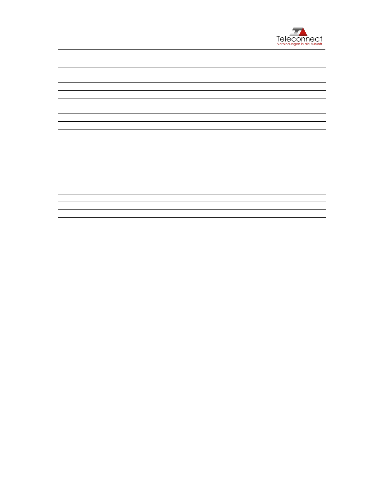
The connector X107 is an unshielded RJ45 connector. It is used for connecting the
SHDSL.EVB.4CH up to four SHDSL lines (according ITU-T G.991.2 [3]). Table 1 shows the
pin definition of X107.
Erase Button
Micro USB:
Power and UART
emulation
Reset Button
Alternative
Power: +5,0V
Alternative
UART
JTAG:
Connection to
AVR debugger/
programmer
Select Mode
Select Bitrate
Ethernet
Connector
SHDSL
Connector
Green LED:
Ethernet Link/
Activity
Amber LED:
Ethernet Error
detected
Green LEDs:
SHDSL line states
(connection established, Training, Idle)
Green LED:
Power
Amber LED:
Status
Red LED:
Error
SHDSL
transceiver
(SHDSL data
pump)
V101
SHDSL
Hybrid
Several
components
Secondary
Protection
D101/D102/
D103/D104
Transformer
L101/L102/
L103/L104
Primary
Protection
Not
available
Connector
X107
X105/X106/
X108/X109
Page 10
SHDSL.EVB.4CH User Manual
Table 1: Pin Definition of X107
Pin Number
Pin Name / Function
1
SHDSL line #2 – Ring
2
SHDSL line #2 – Tip
3
SHDSL line #3 – Ring
4
SHDSL line #1 – Tip
5
SHDSL line #1 – Ring
6
SHDSL line #3 – Tip
7
SHDSL line #4 – Ring
6
SHDSL line #4 – Tip
Typical lines are unshielded twisted pair cables. Any standard Ethernet cable is also usable.
Beside the RJ45 connector X107 SHDSL.EVB.4CH provides the possibility to use the pin
header X105 (SHDSL line #1), X106 (SHDSL line #2), X108 (SHDSL line #3) and X109
(SHDSL line #4) spaced 2.54 millimeters (0.1 in). Table 2 gives the pin definition.
Table 2: Pin Definition of X105, X106, X108 and X109
Pin Number
Pin Name / Function
1
SHDSL line #X – Tip (X = 1...4)
2
SHDSL line #X – Ring (X = 1...4)
The pin header X105 (SHDSL line #1), X106 (SHDSL line #2), X108 (SHDSL line #3) and
X109 (SHDSL line #4) are not mounted by default. It is possible to mount it on both PCB sides
to get an easy test adapter for evaluation or to use the SHDSL.EVB.4CH as a module.
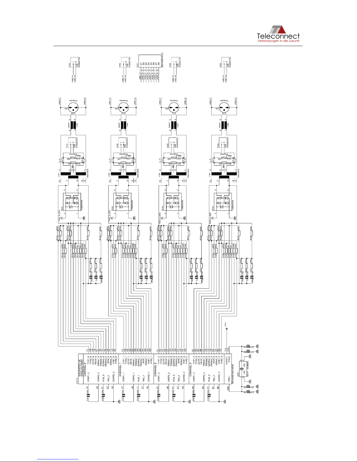
Figure 6 shows the schematic of the SHDSL hybrid with line transformer L101, L102, L103
and L104 and SHDSL data pump V101 (PEF 24628 E).
Components and layout are influencing the SHDSL performance. Teleconnect can assist you
with the selection of additional line protection at raw ambient conditions.
Page 11
SHDSL.EVB.4CH User Manual
Figure 6: (Extract from) Schematic of SHDSL Hybrid
Page 12
SHDSL.EVB.4CH User Manual
3.3 Ethernet Interface via PHY
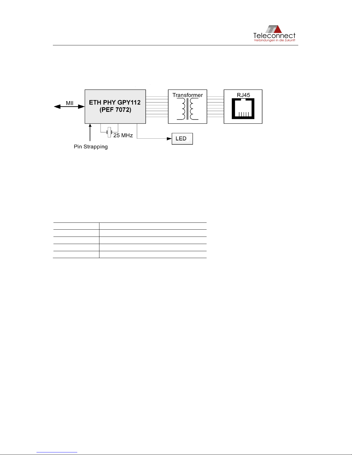
The useable Ethernet interface via PHY is divided in connector, transformer (magnetics) and
Ethernet PHY (see Figure 7).
Figure 7: Ethernet interface
The shielded RJ45 connector X304 is a standard Ethernet interface. It is compatible with
10BASE-T and 100BASE-TX Ethernet according to IEEE 802.3 [1] and can be connected to a
twisted pair medium such as CAT5 cable infrastructure.
Beside the RJ45 connector, SHDSL.EVB.4CH provides the possibility to use the pin header
X302 spaced 2.54 millimeters (0.1in). Table 3 gives the pin definition.
Table 3: Pin Definition of X302
Pin Number
Pin Name / Function
1
TX/RX1 +
2
TX/RX1 -
3
TX/RX2 +
4
TX/RX2 -
The pin header X302 is not mounted by default. It is possible to mount it on both PCB sides to
get an easy test adapter for evaluation or to use the SHDSL.EVB.4CH as module (see
chapter 7).
The transformer L302 connects the connector to the Ethernet PHY GPY112 V201 (PEF7072).
The connection to the SHDSL data pump Intel® SHDSL Chipset V101 is realized via standard
MII interface.
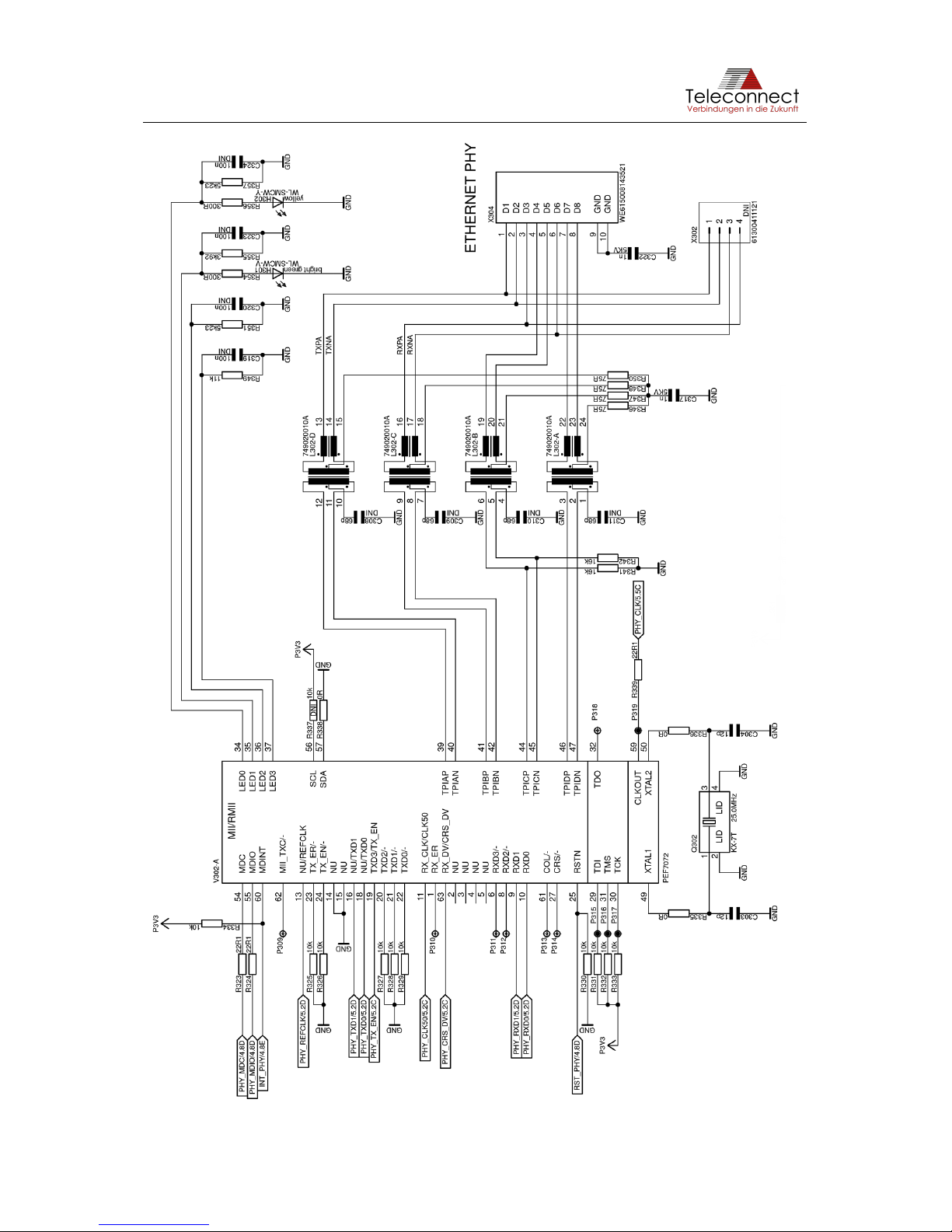
Figure 8 shows the schematic of the Ethernet interface via PHY.
Page 13
SHDSL.EVB.4CH User Manual
Figure 8: Schematic of Ethernet Interface via PHY
Page 14
SHDSL.EVB.4CH User Manual
3.4 Ethernet Interface via Switch
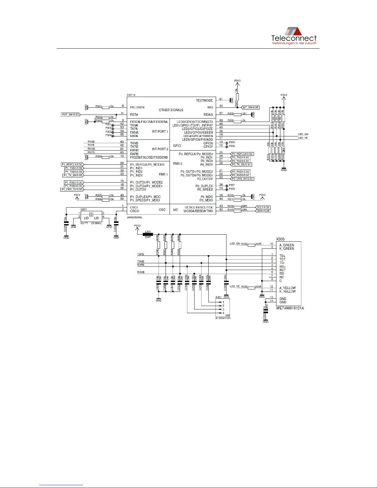
The SHDSL.EVB.4CH consists also an Ethernet interface via switch. It cannot be used at the
current development stage. Figure 9 shows the schematic of the Ethernet interface via Switch.
Figure 9: Schematic of Ethernet Interface via Switch
3.5 Power Supply Input
For the power supply a Micro USB connector Type B with standard pin assignment (according
to USB specification) is used. This enables the EVB to utilize a standard 5V USB plug-in power
supply as power source. We recommend using power supply with at least 1000 mA (better:
2000 mA) output current and a cable with low voltage-drop.
As from our tests it is also possible to connect the Micro USB connector to any self-powered
USB host interface with a short and high-quality USB cable.
Beside the Micro USB connector SHDSL.EVB.4CH provides the possibility to use the pin
header X801 spaced 2.54 millimeters (0.1 in) for power supply. Table 4 gives the pin definition.
Page 15

SHDSL.EVB.4CH User Manual
Table 4: Pin Definition of X601
Pin Number
Pin Name / Function
1
+ 5 V (4.7 … 6.0 V)
2
- (Ground)
The pin header X801 is not mounted by default. It is possible to mount it on both PCB sides
getting an adapter or using the SHDSL.EVB.4CH as module.
The Micro USB connector is also usable for data transmission to the processor. In that case
UART emulation provides a serial interface.
3.6 Power Consumption
The power consumption of the SHDSL.EVB.4CH Evaluation Board is nearly independent from
the traffic on the line. It is maximum 4,9 W.
Boundary conditions:
• Intel® SHDSL Chipsets (PEF 24628 E)
• Firmware: 3.0-R2563
• Function: CO
• Cable length: 1 m
• Power Back Off inactive
• Power 5 V
Table 5: Power Consumption of the SHDSL.EVB.4CH Evaluation Board with full traffic
1-Channel
Bitrate [Kbps]
per SHDSL line
Power [mA]
Power Consumption [W]
TCPAM
Ethernet active
no connection
630
3,15
auto
no
192
710
3,55
16
yes
512
710
3,55
16
yes
2048
720
3,60
16
yes
5696
740
3,70
32
yes
15288
740
3,70
128
yes
4-Channel
Bitrate [Kbps]
per SHDSL line
Power [mA]
Power Consumption [W]
TCPAM
Ethernet active
no connection
660
3,30
auto
no
192
800
4,00
16
yes
512
800
4,00
16
yes
2048
890
4,45
16
yes
5696
940
4,70
32
yes
15288
940
4,70
128
yes
3.7 Serial Interface (UART)
SHDSL.EVB.4CH features a serial interface (UART) for controlling and monitoring purposes.
The interface is usable in two ways: UART emulation via USB interface and TTL-compatible
interface via connector X601. Both interfaces have the same function and can work
simultaneously.
Page 16
SHDSL.EVB.4CH User Manual
The pin header X601, also named “UART”, is not mounted by default. It is possible to mount
any 2.54 millimeters (0.1 in) spaced pin header at both sides of the PCB. So, the soldering
pads are usable as an easy test adapter for evaluation or as a module placed on a host board.
Table 6 shows the pin definition of X601.
Table 6: Pin Definition of X601
Pin Number
Pin Name / Function
1
+ 3.3V
2
TX (sending data from SAM4S)
3
RX (receiving data by SAM4S)
4
Ground
3.8 Debug interface
The controlling processor of SHDSL.EVB.4CH is Microchip ATSAM4SD32C. Based on the
powerful ARM® Cortex®-M4 core, the SAM4S series gives improved performance, low power
consumption and an easy to use processor. The processor gives much more performance and
periphery than SHDSL chipset needs. This offers a good basis for the development of own
software.
With the connector X602 (“JTAG”) SHDSL.EVB.4CH provides a compatible interface to
Microchips development and debugging tools. For example, the SAM-ICE™ Microchips JTAG
Emulator for ARM® core-based microcontrollers is usable.
X602 is a 2.54 millimeter (0.1 in) spaced pin header. The pin definition is given at Table 7.
Table 7: Pin Definition of X602
Pin Number
Pin Name / Function
1
TCK
2
Ground
3
TDO
4
+ 3.3V
5
TMS
6
Reset (NRST)
7
Not used
8
Not used
9
TDI
10
Ground
3.9 Control and Monitoring Interface
SHDSL.EVB.4CH provides on board software usable for many standard applications. For
configuration and status information, several buttons, switches and LEDs are available. The
following section gives more information.
3.9.1 Buttons
There are two buttons available. The first is the button S601 called “RESET”. Pressing this
button triggers hardware reset of the processor and the SHDSL interface. The software restarts
and makes new initialization of SHDSL.EVB.4CH.
The second button is the button S602 called “ERASE” with two functions. During reset (Reset
button is also pressed) the whole flash memory will be cleared. This is only necessary for
updating a complete firmware image including bootloader for example. A normal firmware
update can be done by the CLI firmware update procedure. Please see chapter 5.3.5 Firmware
update for further information. During runtime and active BSI mode (DIP switch 3 = 0),
Page 17
SHDSL.EVB.4CH User Manual
additional information about software, SHDSL firmware version and SHDSL configuration will
be printed to serial interfaces (UART and USB) if the button “ERASE” is pressed.
Please see Figure 4 for the location of the buttons.
3.9.2 DIP switches
There is a protective tab on top of DIP switch. Please remove it from the DIP switch before first
use. The dual in-line package switch S604 is used for selection of operation mode. If the switch
position is stable for more than four seconds the software will accept the new setting and
reconfigure the SHDSL chipset.
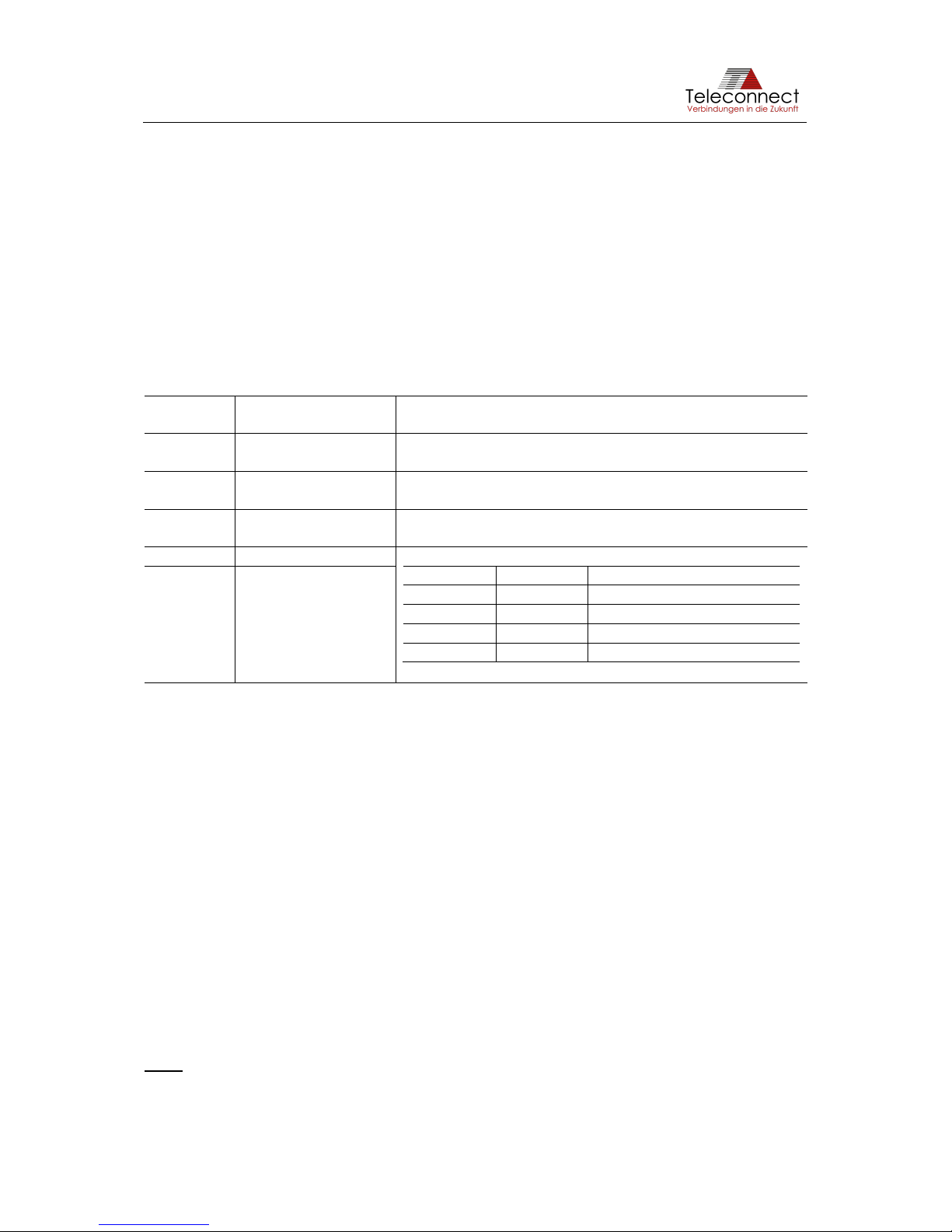
There are five switches available. Table 8 describes the function of the DIP switch called
“MODE”.
Table 8: Function of “MODE” Switch S604
Switch
number
Description
Switch function
1
Device Mode
On: STU-C (Master, CO mode)
Off: STU-R (Slave, CPE mode)
2
Extended Rates
On: Enables extended bitrates (64...15336kbps)
Off: ITU-T standard bitrates (192...5696kbps)
3
User Interface Mode
On: CLI is active (only with SW Packages P3)
Off: BSI is active
4
Line using (LU1)
The number of used SHDSL lines will be defined
LU2
LU1
Number of SHDSL lines
0
0
4 lines (1-4) (normal mode)
0
1
3 lines (1, 2 and 4)
1
0
2 lines (1 and 4)
1
1
1 line (1)
5
Line using (LU2)
SHDSL is a point to point connection. SHDSL interconnections need two different device
modes, called SHDSL Termination Unit Central Office (STU-C) and SHDSL Termination Unit
Remote (STU-R). Switch 1 is usable for device mode selection. Please ensure to switch one
modem to STU-C and the other to STU-R. Otherwise no data transmission will be established.
Beside the standard data rates according to ITU-T G.991.2 [3] Intel® SHDSL Chipset provides
higher (and lower) data rates. Intel® SHDSL Chipset is capable to use about three times higher
transmission speed compared to high speed standard SHDSL connections. The lower bitrates,
for example, match better to ISDN-BRI. Switch 2 selects full performance or compatibility to
other SHDSL equipment. For SHDSL systems with Intel® SHDSL Chipset on both sides Intel®
recommend using the extended bitrates (switch 2 on). For highest interoperability let switch 2
off.
If more than one SHDSL line will be used the data rate settings will be set to all lines. It therefor
follows that the data rate will be a multiple of number of lines and data rate.
Example:
configured data rate: 192 Kbps
number of SHDSL lines: two
complete data rate: 2 x 192 Kbps = 384 Kbps
Note: The test mode configuration via switch number 4 and 5 like at the SHDSL.EVB.1CH is
not supported with SHDSL.EVB.4CH. This configuration can be done by the CLI (chapter 5.3).
Page 18

SHDSL.EVB.4CH User Manual
3.9.3 Rotary switch (10 pole)
The rotary switch S603 (named “BITRATE”) is used for selection of the bitrates. Table 9 shows
choice of bitrates.
If the switch position is stable for more than 4 seconds the software will accept the new setting
and reconfigure the SHDSL chipset. An established data transmission will be interrupted
during reconfiguration.
Table 9: Selectable Bitrates of SHDSL.EVB.4CH
Switch
position
Extended Rates
(DIP switch 2)
Line probing
Bitrate [Kbps]
PAM
0 (default)
Off
Enabled
192…5696
Auto
1
Off
Disabled
192
16
2
Off
Disabled
384
16
3
Off
Disabled
512
16 4 Off
Disabled
768
16
5
Off
Disabled
1536
16
6
Off
Disabled
2048
16
7
Off
Disabled
2304
32
8
Off
Disabled
3072
32
9
Off
Disabled
5696
32
Switch
position
Extended Rates
(DIP switch 2)
Line probing
Bitrate [Kbps]
PAM
0 (default)
On
Enabled
64…15336
Auto
11
On
Disabled
64 *
4
2 *
On
Disabled
192 *
4
3 *
On
Disabled
192 *
8
4 *
On
Disabled
2496 *
4
5 *
On
Disabled
5056 *
8
6 *
On
Disabled
7616 *
16
7 *
On
Disabled
10176 *
32
8 *
On
Disabled
12736 *
64
9 *
On
Disabled
15288 *
128
The best choice for most applications is switch position 0 which enables the Power
Measurement Modulation Session (PMMS), also called “Line Probing”. PMMS works like an
automatic mode, in that case SHDSL chipset selects the highest given bitrate for actual noise
floor and loop length. The bitrate differs depending on extended rates that are enabled or not
(see Table 8). The target SNR margin is always set to 6 dB.
3.9.4 Rotary switch (16 pole)
The rotary switch S501 (named “HARDWARE CONFIG”) cannot be used at the current
development stage.
3.9.5 LEDs
Nine LEDs indicating the current state of SHDSL.EVB.4CH. For the location of the LEDs
please have a look at Figure 4 on page 9.
1
The configuration of fixed bitrates in extended rates mode is only possible by SHDSL Master (CO
mode, STU-C). The SHDSL Slave (CPE mode, STU-R) ignores the switch position and always uses
line probing (switch position 0).
Page 19

SHDSL.EVB.4CH User Manual
The green LED H801 “POWER” indicates that power is connected. This LED is on if the board
is active and off if the SHDSL.EVB.4CH is not powered up.
The four green LEDs H501 - H505 signaling the status of the SHDSL lines. The LED is off if
SHDSL is not active (e.g. during initialization). If the SHDSL chipset is initialized, the LED
blinks slowly (approximately 1Hz). The SHDSL chipset is ready to work and waits for detecting
counterpart station. Once the counterpart station is detected, the training process starts and
the LED blinks faster (approximately 3 Hz). This process takes some seconds and if the
SHDSL chipset can establish a SHDSL link the LED stops blinking.
The state of the Ethernet port is indicated by the green LED H301 and the amber LED H302.
The LEDs are off if the Ethernet PHY hasn’t detected any Ethernet counterpart. The green
LED goes on if an Ethernet link is established. The amber LED starts blinking if data
transmission is active.
The amber blinking LED H505 (“STATE”) shows the normal status of the SHDSL.EVB.4CH. If
the amber LED stops blinking or switch off a software error has occurred. In this case the
software Watchdog will be resetting the board after 30 seconds.
A red LED H506 (“ERROR”) indicates an error state. For normal operation this LED is off. The
LED is on or starts blinking if an error has occurred. The error type will also print to the serial
interface (USB UART emulation and hardware UART).
Page 20

SHDSL.EVB.4CH User Manual
4 Software
4.1 Updating Firmware
The control and monitor processor ATSAM4SD32C supports Microchip SAM Boot Assistance
(SAM-BA), an open set of tools for programming the Microchip ARM® core-based
microcontrollers. This is only necessary for updating a complete firmware image including
bootloader for example. A normal firmware update can be done by the CLI firmware update
procedure. Please see chapter 5.3.5 Firmware update for further information.
The following section provides a guide on how to install the in-system programmer and how to
use it.
4.1.1 Preparation
If you have already installed the SAM-BA programmer, please go to the next section.
Please regard, that to date SAM-BA revision 2.18 is proven to work correctly with the
microcontroller device SAM4S at SHDSL.EVB.4CH. Subject to change without notice.
This is a guide on how to install the in-system programmer on your PC.
1. Download the version 2.18 of SAM-BA in-system programmer from Microchip web
page (http://www.microchip.com). (regard comment above)
2. Install the downloaded software on your PC. Follow the instruction of the installer of
user interface (more info: see "sam-ba user guide.pdf" or "usb_notice.html")
3. Connect the SHDSL.EVB.4CH with a Micro-USB 2.0 cable (USB-Micro-B connector
to USB-A connector) to your PC and clear the whole memory including the firmware
of EVB by pressing "RESET" and "ERASE" button at the same time.
4. Install the driver for the unknown device.
(For Microsoft Windows 10 users this step is not necessary.)
Please select "search for driver software at local computer". The driver is located in
your installation directory "<your SAM-BA installation directory>\drv".
Attention: do not select "automatic search for driver software" (search in the internet).
Select "Install from ATMEL Rousset" trust. After a while the driver software "AT91
USB to Serial Converter" is installed successfully and assigned to a COM port.
For more information please have a look at "<your SAM-BA installation
directory>\doc\usb_notice.html"
If you have installed another revision than 2.18, you may experience errors with the driver.
Or if Windows version (8 or lower) loads another driver version via Windows Update called
"Bossa Program Port" please do not hesitate to contact us by E-mail: [email protected].
The “Bossa Program Port” driver should work for Windows 10.
4.1.2 Using the in-system programmer
Before starting, prepare the new firmware image. You cannot generate it by yourself. Please
use latest firmware image only provided by Teleconnect:
http://www.teleconnect.de/xdsl/socrates-evb
You need the firmware image in *.bin file format.
1. Connect the SHDSL.EVB.4CH to your PC using the micro USB cable.
2. Press both buttons of the EVB (“RESET” and “ERASE”) at the same time. This clears
the whole memory including the firmware of EVB.
Page 21
SHDSL.EVB.4CH User Manual
3. Disconnect and reconnect the USB connection of EVB. After reconnection, the LEDs
“SHDSL STATE” and “ERROR” will not light up/flash. This indicates that no firmware
is present.
4. Call the SAM-BA programmer
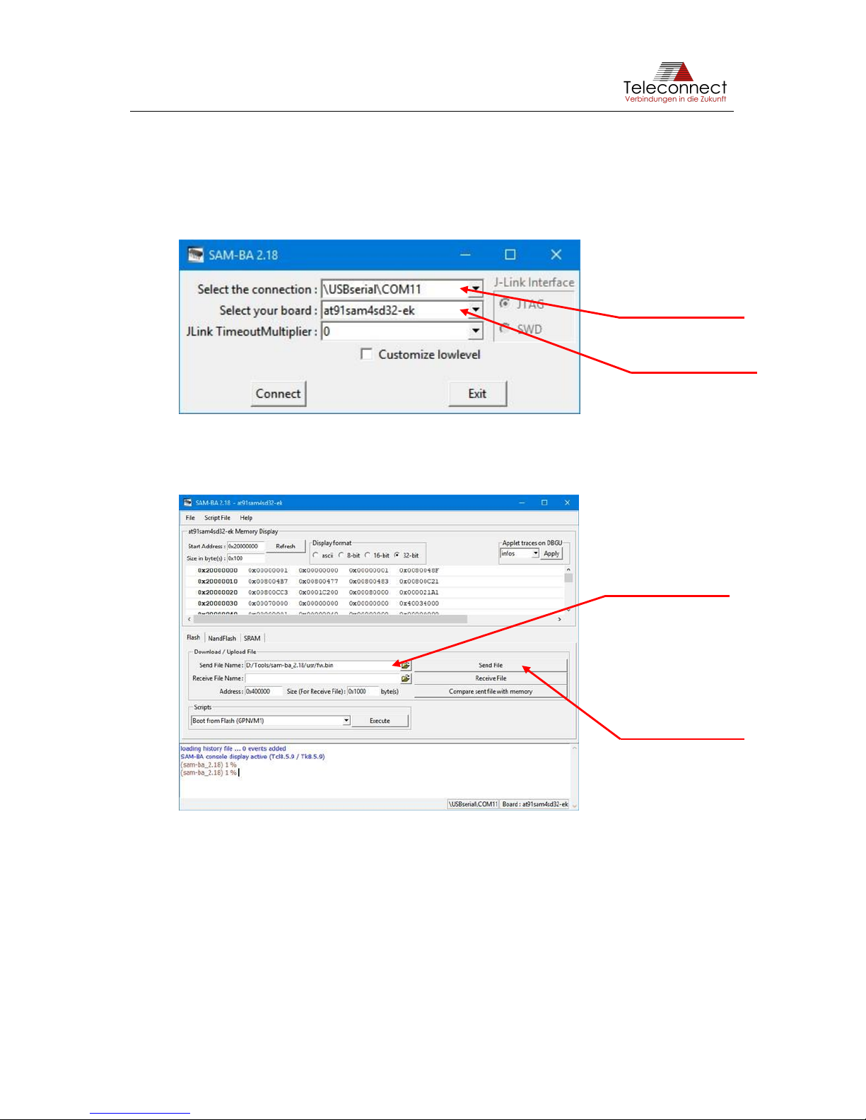
5. Select the connection, e.g. COM1 or \USBserial\COM11, select your board and
choose at91sam4sd32-ek as board type.
Figure 10: SAM-BA menu: select connection and board
6. Press button "Connect".
7. Select the firmware image binary and press “Send File” button.
Figure 11: SAM-BA menu: select firmware image and download them
8. The file will download. After that you can lock the involved lock regions or not.
Select your
COM port
Select
at91sam4sd32-ek
Select the
firmware image
Download the
image to
SHDSL.EVB.4CH
Page 22
SHDSL.EVB.4CH User Manual
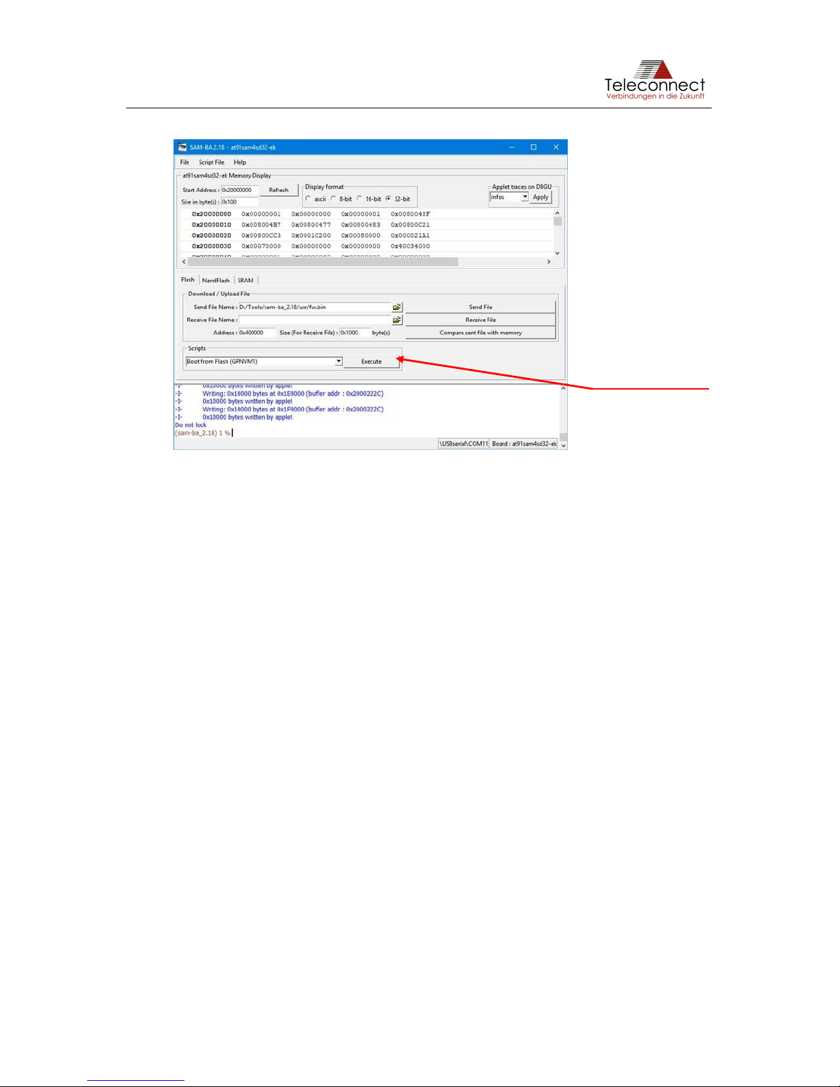
9. Press the button “Execute” and close the SAM-BA programmer.
Figure 12: SAM-BA menu: press execute
Remark: With some SAM-BA versions you may get the following error sometimes:
ScriptGPNMV 2-E-Set GPNVM1 failed.
In that case you must disconnect and reconnect the power connection. The
SHDSL.EVB.4CH should work normally.
10. Disconnect and reconnect the USB connection of SHDSL.EVB.4CH. Ready.
4.2 SHDSL.EVB.4CH Firmware 3.0
SHDSL.EVB.4CH comes with on-board software "Firmware 3.0" ready to use. It works
autonomous without connection to host controller. The configuration is selectable by switches
(see section 3.9).
The firmware includes the following main features:
• Adjust the line rate with enabled Line probing,
• Select several fixed line rates (see Quick Start Guide),
• Support for EFM-CU,
• Line coding: 16 and 32 TC-PAM according to ITU-T G.991.2 [3],
• Extended rates configuration (min rate: 64kbps, max rate: 15336kbps),
• Monitoring of basic SHDSL line parameters and
• Usage of one, two, three or four SHDSL lines (PAF bonding).
Teleconnect provides this free firmware image for evaluation proposes only. You can buy
software license for commercial use from Teleconnect. Please see an overview over possible
functionalities and packages in the following chapter. Beside this, Teleconnect can assist you
in SHDSL software development for your customized version.
The firmware revision 3.0 of SHDSL.EVB.4CH includes PEF24628 driver by Intel. You can use
this driver for your own software development.
Press this button
Page 23
SHDSL.EVB.4CH User Manual
4.3 Functions and packages
The following chapter should give you a short overview over functionalities provided by
Teleconnect. All packages are included in this free firmware image for evaluation purposes.
For further information and prices please contact us at [email protected].
Table 10: Available software packages and functions
Package
number
Function
P1
basic software
P2
basic management (BSI)
P3
advanced management (CLI)
P4
PAF bonding for SHDSL.EVB.4CH
P5
networking (Telnet, Webserver etc.)
P6
bootloader and update
P7
ATM support (only on request and additionally customization needed)
P8
advanced operation (Emergency freeze, EOC handling, VLAN, BERT etc.)
S
predefined configurations
Page 24

SHDSL.EVB.4CH User Manual
5 User Interfaces
There are two management versions available:
1. BSI - Basic Status/SHDSL Interface (P2 is needed) (more information in chapter 5.2),
2. CLI - Command Line Interface (P3 is needed) (more information in chapter 5.3).
The two different user interface versions can be activated via DIP switch 3:
• On: CLI is active,
• Off: BSI is active (more in information in Table 8).
5.1 Establish a Connection
SHDSL.EVB.4CH provides user interface via serial interface (UART) and Telnet interface.
For serial interface are two equal alternatives available: TTL compatible interface and
emulation via USB (see section 3.7). The baud rate is 115.2 kbaud/s with 8 data bits, 1 stop
bit and none parity. With a Terminal Emulation Software like PuTTY, TeraTerm and Minicom
or other VT-100 compatible software program you can establish a connection to the evaluation
board.
To establish a connection via the Telnet interface please use following settings: IPv4 address:
10.10.10.1 (default IP), Netmask: 255.255.255.0.
5.2 BSI - Basic Status/SHDSL Interface
The BSI interface provides a cyclic printout of SHDSL status to UART and / or USB only.
During startup you will see for example the following print out:
Start SHDSL.EVB.4CH bootloader (3.0-R2559) ...
Start application ...
-- Startup --
=======================================================
Boot-Ver#: 3.0-R2559
SW-Ver#: 3.0-R2569
PHY-Ver#: 1.1-2.1.0__001
IDC-Ver#: 2.1.0.0
Serial#: 0123.E60B.C44F.2007
Vendor: Teleconnect GmbH
Am Lehmberg 54 - 01157 Dresden - Germany
[email protected]
Copyright (c) Teleconnect GmbH 2013-2018.
All rights reserved.
=======================================================
Page 25

SHDSL.EVB.4CH User Manual
SHDSL Configuration:
=======================================================
Active: yes
Lines: 1,2,3,4
Masterline: 1
CO/CPE: CPE
TC Layer: EFM
Ext. rates: Enabled
Lineprobing: Enabled
Bitrate min: 64 kbps
Bitrate max: 15336 kbps
PAM: Auto
Annex: ANNEX_B
SNRM: 6 dB
=======================================================
SDFE download ... ok.
IDC download ... ok.
IDC start ... ok.
Line #1 Line #2 Line #3 Line #4
Linestate: DOWN_NOT_READY DOWN_NOT_READY DOWN_NOT_READY DOWN_NOT_READY
Mode: STU-R (CPE) STU-R (CPE) STU-R (CPE) STU-R (CPE)
Bitrate/PAM:
SNRM/LATN(NE):
SNRM/LATN(FE):
0======================================================
If the hardware configuration is changed (e.g. new switch position of rotary switch) you get a
confirmation print out like that:
HW Config changed (dip:0x01, rot:1)
SHDSL config activate successful
During operation you get a cyclic status print out like that:
Line #1 Line #2 Line #3 Line #4
Linestate: UP_DATA_MODE UP_DATA_MODE UP_DATA_MODE UP_DATA_MODE
Mode: STU-C (CO) STU-C (CO) STU-C (CO) STU-C (CO)
Bitrate/PAM: 192 kbps/16-TCPAM 192 kbps/16-TCPAM 192 kbps/16-TCPAM 192 kbps/16-TCPAM
SNRM/LATN(NE): 29 dB/ 1 dB 28 dB/ 1 dB 29 dB/ 1 dB 28 dB/ 1 dB
SNRM/LATN(FE): 28 dB/ 1 dB 27 dB/ 1 dB 26 dB/ 1 dB 27 dB/ 1 dB
==========================================0============
If you press the “ERASE” button, you will get a summary of state information. It looks like this:
#######################################################
Boot-Ver#: 3.0-R2559
SW-Ver#: 3.0-R2569
PHY-Ver#: 1.1-2.1.0__001
IDC-Ver#: 2.1.0.0
Serial#: 0123.E60B.C44F.2007
Vendor: Teleconnect GmbH
Am Lehmberg 54 - 01157 Dresden - Germany
[email protected]
Copyright (c) Teleconnect GmbH 2013-2018.
All rights reserved.
=======================================================
Page 26

SHDSL.EVB.4CH User Manual
SHDSL Configuration:
=======================================================
Active: yes
Lines: 1,2,3,4
Masterline: 1
CO/CPE: CO
TC Layer: EFM
Ext. rates: Disabled
Lineprobing: Disabled
Bitrate min: 192 kbps
Bitrate max: 192 kbps
PAM: 16-TCPAM
Annex: ANNEX_B
SNRM: 6 dB
#######################################################
Please note, there is a special behavior in Microsoft Windows environment. The COM port
initializing happens during the connection to the USB port. During this process you get the
COM port number and then you can assign a terminal program. So, it is possible you miss the
first notifications.
Further a reset of SHDSL.EVB.4CH initiates a new initialization of the COM port. Your
connection to the terminal program will be lost.
5.3 CLI - Command Line Interface
The command line interface (CLI) is an advanced user interface with session-management
and auto-completion. The CLI has a CISCO®-like syntax. With it an advanced configuration
and status management is possible. The CLI has a VT100 emulation for UART, USB and
Telnet.
The focus of the CLI was at:
• a hierarchical organization of (sub-)menus and commands,
• a command history,
• auto-completion of commands which are unique,
• password protection.
5.3.1 Login
The login to SHDSL.EVB.4CH via CLI is password protected. Every unit has its own password
and it depends on your serial number. The following output will be displayed:
## Thanks for using our SHDSL evaluation board. Please register ##
## to get your password for free. Send your serial number and ##
## your contact information to [email protected] ##
please enter password
password:
Please contact us at [email protected], and we can provide you your password. When
you have changed the first password into your individual password the output will be
deactivated (please see chapter 5.3.3).
The next password input will be delayed after wrong password.
If a user was successfully authenticated his session is exclusive - Simultaneous login attempts
from other interfaces will be suppressed. Unused CLI sessions will be terminated after 5
minutes of inactivity.
Page 27
SHDSL.EVB.4CH User Manual
5.3.2 CLI commands
The CLI commands are organized hierarchical in various directories. The amount of functions
and menus in the CLI depends on the enabled features during compilation. For instance, it is
possible to disable Networking (no package P5). Consequently, the CLI menu "iface net" is not
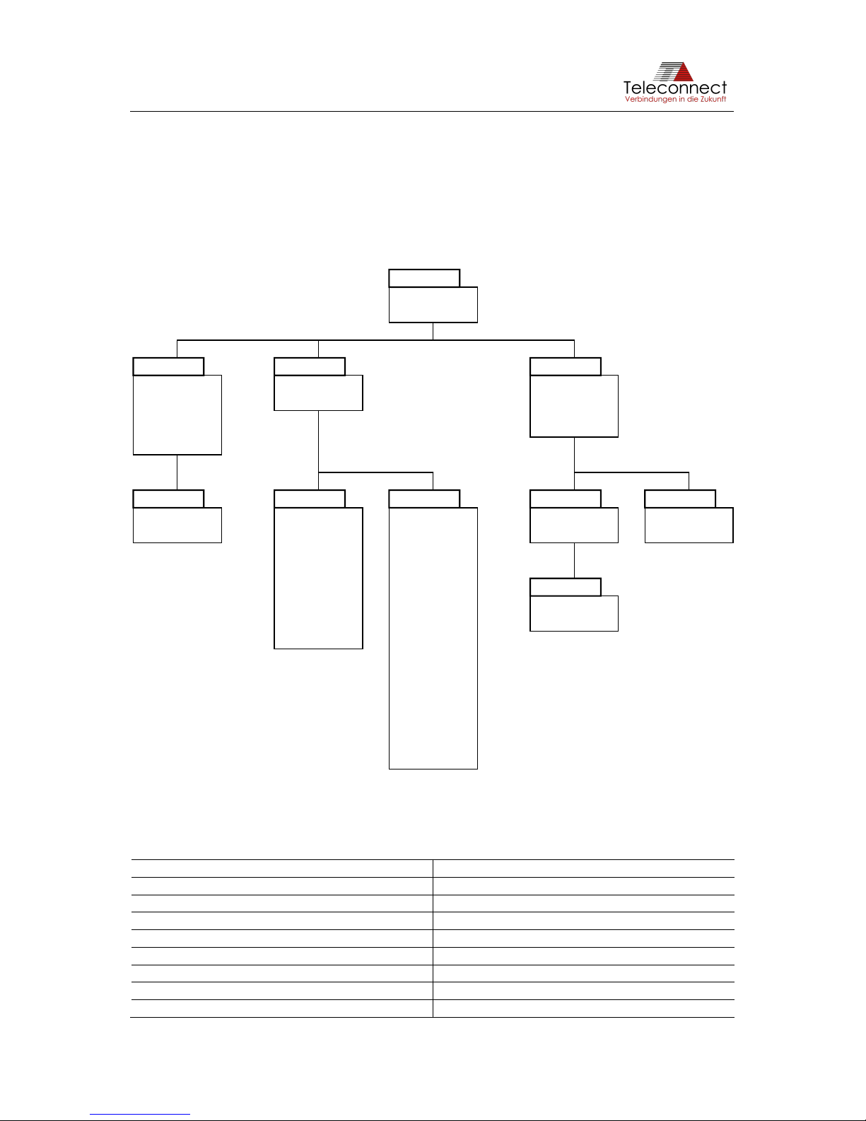
available.
The following diagram gives an overview of the menu hierarchy.
Figure 13: CLI menu tree
Table 11 gives an overview of the CLI menus and their function.
Table 11: CLI menus
Menu
Function
/config/
Manage system configuration sets
/config/upload/
Upload new configuration sets
/iface/
Manage interfaces
/iface/net/
Manage network interface
/iface/shdsl/
Manage SHDSL interface
/sys/
Get the system information
/sys/fw/
firmware update functions
/sys/syslog/
Access the systems error log
-- none --
copy
default
delete
dump
show
activate
check
info
password
reset
status
ascii
xmodem
activate
check
enabled
gateway
ip
netmask
show
side
vlanid
activate
annex
check
ef
enabled
iop
line
mode
pam
rate
ratemode
reset
show
snrm
status
tclayer
testmode
activate
show
clear
show
ascii
xmodem
config
root
iface sys
netupload
update
shdsl fw syslog
Page 28
SHDSL.EVB.4CH User Manual
In addition to the menu specific functions, the following navigation functions are available in
every menu:
• exit (exit the current menu and move up in the menu hierarchy)
• logout (end the CLI session)
• ‘...’ (3 dots) (go to root directory)
• ‘..’ (2 dots) (exit the current menu and move up in the menu hierarchy - see also ’exit’)
To get a list of available subdirectories and functions in the current menu enter a question mark
("?") directly following the prompt. It is also possible to get context sensitive help for your
entered command. This can be achieved by pressing question mark after typing a command.
Depending on whether the command refers to a directory of a function, a list of available
subdirectories and functions or the function-specific help will be shown.
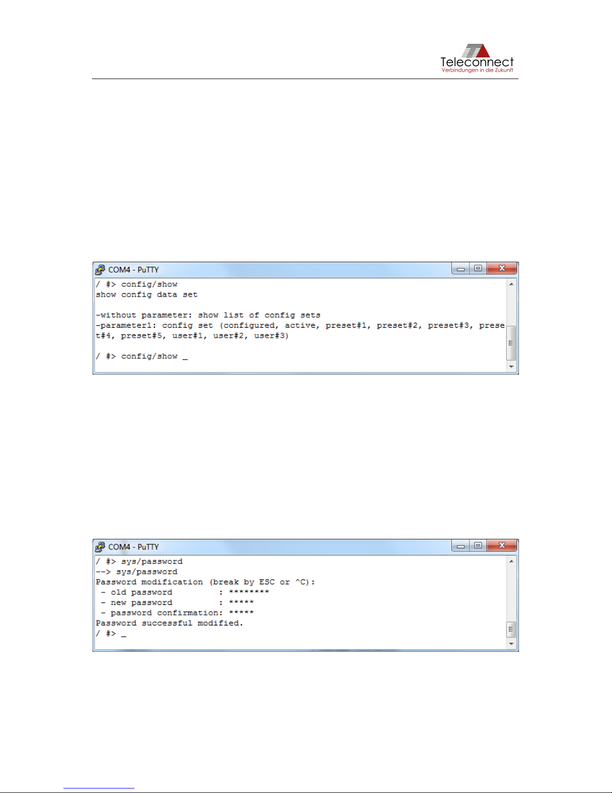
Figure 14: CLI example: config/show ?
When typing commands, it is always possible to shorten subdirectory or function names. By
pressing <tab> the entered command will be completed. If a command is ambiguous CLI will
provide a list of possible completions.
5.3.3 Password modification
Via command „sys/password“ the password can be changed into an individual one.
The current password is needed to change it. It will be saved at flash memory after the
confirmation of the new password and is active for the next login. The password needs
between 5 and 20 characters.
Figure 15: CLI example: password modification
Page 29
SHDSL.EVB.4CH User Manual
5.3.4 Configuring the system
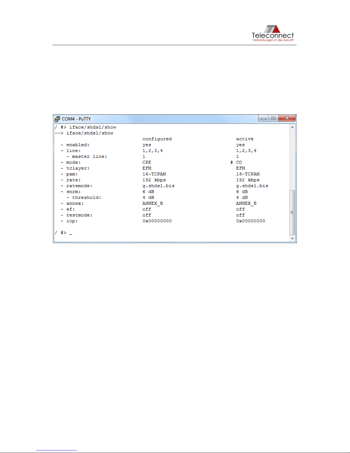
Changing settings is done in two steps. First the configuration is changed and in a second step
it must be activated. The show command provided in the /iface/shdsl directory will display both,
the current configured and the active (currently running) settings. Differences between them
are indicated by an "#" sign.
The following example shows SHDSL parameters, after the mode has been modified from CO
to CPE (with command: "iface/shdsl/mode cpe")
Figure 16: CLI example for show modified SHDSL configuration
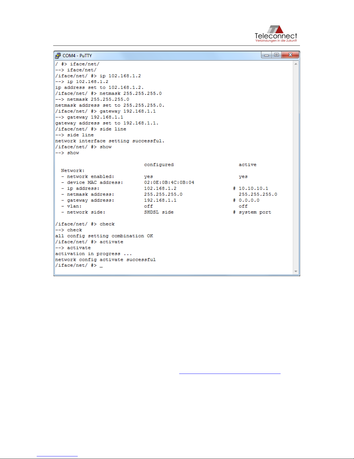
All configuration options related to the IP interface can be found in the directory /iface/net.
Network can either be used on SHDSL line side or system side (Ethernet port) of one SHDSL
Configuration.
The following example changes IP address, netmask, gateway and side of the network
interface.
Page 30
SHDSL.EVB.4CH User Manual
Figure 17: CLI example for net configuration
5.3.5 Firmware update
The firmware update takes place in 4 steps:
1. determination of the inactive firmware bank
2. upload of firmware file
3. activation of new firmware
4. reset and reboot module.
The transfer of the packed fw binary file (* .bin) takes place on the UART and USB interface
using the Classic XMODEM protocol (see also https://en.wikipedia.org/wiki/XMODEM) with a
128-byte data packet.
The telnet interface uses a packed and specially prepared ASCII file (*, asc). This file can be
easily sent to the interface.
Both terminal applications ("Transfer XMODEM send" and "File send") are not supported by
Putty by default. At this point we recommend the terminal program TeraTerm, where both
actions can be found under the menu item "File".
Page 31
SHDSL.EVB.4CH User Manual
5.3.5.1 Determination of the inactive firmware bank
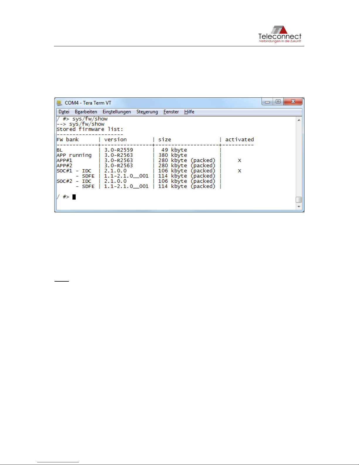
The "sys/fw/show" command lists the fw parts stored in the flash. Behind each application
firmware and an Intel® SHDSL chipset firmware, a cross is set in the column "activated", which
marks the active fw bank. The other fw bank is the inactive one to which a fw upload can be
executed.
Figure 18: CLI example for show stored firmware list
5.3.5.2 Upload of fw file
With the command "sys/fw/upload/xmodem <fw-bank>" (with fw-bank: app1, app2, soc1, soc2)
for UART and USB access or command "sys/fw/upload/ascii <fw -bank>" for telnet access the
upload is started.
Note: Please provide the firmware file in a location on the PC that can be easily navigated
within 60s.
A line appears, that now within the next 60s the file transfer should be started.
APP#2 firmware update started - please start data transmission with classic XMODEM
protocol (in next 60 sec.).
At this point, the terminal enters a mode in which no text output can be made on the console.
Notes do not take place.
If no action is taken via the interface, the upload process stops.
Data receive timeout - APP#2 firmware update process disabled.
APP#2 firmware update failed.
/ #>
On the other hand, if the transmission starts after the 60s have elapsed, e.g. if the file selection
took too long, the upload process timed out on the board, but the terminal continues the action
undisturbed. It can happen that the start of the file transfer leads to a series of error outputs.
In this case, the upload of the firmware file can be repeated.
After successful file transfer (may take several minutes), the output is made:
APP#2 firmware update successful finished.
/ #>
Page 32

SHDSL.EVB.4CH User Manual
5.3.5.3 Activation of new firmware
After the firmware file upload, the new firmware is not yet activated. If the module is rebooted,
the current firmware will continue to be used.
To change the active firmware, use the command "sys/fw/activate <fw-bank>" (with fw-bank:
app1, app2, soc1, soc2).
5.3.5.4 Reset and reboot of module
A reset of the module with the command "sys/reset" or a power-on reset causes the firmware
to be used with the activation flag at startup. If the previously running firmware is not the one
of the active firmware bank, the firmware is unpacked and copied to the flash area of the
current firmware and started.
This completes the firmware update process.
Page 33

SHDSL.EVB.4CH User Manual
6 Operation
The following description gives an easy way to make a data connection using SHDSL. You
need at least one Intel® SHDSL Chipset and one other standard compliant SHDSL modem.
However, the easiest way to make a SHDSL connection is to use two SHDSL.EVB.4CH.
6.1 Start-up with two boards
1. Verify settings: DIP switch 2 on (for highest possible data rate up to 15 Mbps), all other
DIP switches off, rotary switch on 0 (exempt you wish a special bit rate).
2. Switch on Device Mode (DIP switch 1) for master mode (STU-C) at one board, the
other stays in slave mode (STU-R, DIP switch 1 off).
3. Select the SHDSL line number used (DIP switch 4 and 5 - see Section 3.9.2).
4. Connect both SHDSL connectors together. You can use a standard Ethernet patch
cable.
5. Power up both boards, e.g. connect the micro USB plugs to PC.
• The power LED, Error LED, Status LED and the SHDSL LEDs go on.
• After some seconds the red Error LED and green SHDSL LEDs go off, the amber
Status LED is blinking.
• The SHDSL LEDs start blinking slowly after some seconds.
• The SHDSL LEDs blink fast during SHDSL Training.
• The SHDSL LEDs are on if the SHDSL connection is established.
6. Disconnect the Ethernet cable from your computer; plug it into the Ethernet connector
of the first board. Connect the wall outlet to the Ethernet connector to the second board.
• The green Ethernet LED is on if Ethernet connection was established.
• The amber Ethernet LED starts blinking indicating Ethernet traffic.
7. Ready! You are using SHDSL for your data connection.
Page 34

SHDSL.EVB.4CH User Manual
7 Using SHDSL.EVB.4CH as Module
7.1 Scope
The main goal of SHDSL.EVB.4CH is a simple evaluation platform of the Intel® SHDSL
Chipset. Beside this it is possible to use SHDSL.EVB.4CH as SHDSL EFM module. That is
why SHDSL.EVB.4CH is made in a small form factor, not typical for evaluation platforms. This
may be interesting for small volume applications.
This chapter covers using SHDSL.EVB.4CH as a module.
7.2 Connection
If SHDSL.EVB.4CH is used as module, it can power up via X801. Please connect pin 1 to + 5
V (4.7 … 6.0 V) and pin two to Ground. The SHDSL line should connect to X105, X106, X108
and X109 and the Ethernet interface to X302. Optionally, a control and monitor interface are
available to connect at X601. If you want to use it, please connect it to serial interface of host
processor. There is one mounting hole at EVB. It can be used for fixing the EVB to the host
board via an M2.5 screw.
The pin header connectors X105, X106, X108 and X109, X302, X601 and X801 are not
mounted by default and can be populated if necessary.
The connectors X107, X304 and X604 are not used and should be left open.
7.3 Protection
The SHDSL.EVB.4CH is conceptualized as an evaluation platform. For this, SHDSL.EVB.4CH
includes only basic protection. It is possible to add additional protection circuits on the host
board to use SHDSL.EVB.4CH in rough environments.
For further assistance you can contact Teleconnect at [email protected].
Page 35

SHDSL.EVB.4CH User Manual
8 Literature
[1]
IEEE, „IEEE Std. 802.3-2008, Section 5: Part 3: Carrier Sense Multiple Access with Collision
Detection (CSMA/CD) access method and physical layer specifications,“ 2008-12-26.
[2]
Teleconnect GmbH, SOCRATES Series, SHDSL.EVB.1CH, User Manual, Dresden, 01/2019.
[3]
ITU, „ITU-T G.991.2: Single-pair high-speed digital subscriber line (SHDSL) transceivers,“ 12/2003.
Page 36

SHDSL.EVB.4CH User Manual
Appendix A. Quick Start-up guide
The following description provides an easy way to establish a data connection using SHDSL. You need
at least one SHDSL.EVB.4CH and one other standard compliant SHDSL EFM modem. However, the
easiest way to make a SHDSL connection is to use two SHDSL.EVB.4CH. The following sections are
describing two common use cases.
Realize Long-Reach-Ethernet Connectivity
• Check your existing application for an existing Ethernet (ETH) interface and connect to EVB.
• Select bit rate and operation mode
o standard (192…5696 Kbps) or extended bit rate (64…15336 Kbps),
o master mode (STU-C) or slave mode (STU-R).
• Select number of SHDSL lines.
• Connect 5 V power supply to the Micro USB connector.
o The power LED, Error LED, Status LED and the SHDSL LEDs go on.
o After some seconds the red Error LED and green SHDSL LEDs go off, the amber Status
LED is blinking.
o The SHDSL LEDs start blinking slowly after some seconds.
• Connect SHDSL lines.
o The SHDSL LEDs blink fast during SHDSL Training.
o The SHDSL LEDs are on if the SHDSL connection is established.
• Ready! You are using SHDSL for your data connection.
Start-up using two boards
1. Verify settings: DIP switch 2 on (for highest possible data rate up to 15 Mbps), all other DIP
switches off, rotary switch on 0 (exempt you wish a special bit rate).
2. Switch on Device Mode (DIP switch 1) for master mode (STU-C) at one board, the other stays
in slave mode (STU-R, DIP switch 1 off).
3. Select the SHDSL line number used (DIP switch 4 and 5 - see Section 3.9.2).
4. Connect both SHDSL connectors together. You can use a standard ETH patch cable.
5. Power up both boards. E.g. connect the micro USB plugs to PC.
• The power LED, Error LED, Status LED and the SHDSL LEDs go on.
• After some seconds the red Error LED and green SHDSL LEDs go off, the amber Status
LED is blinking.
• The SHDSL LEDs start blinking slowly after some seconds.
• The SHDSL LEDs blink fast during SHDSL Training.
• The SHDSL LEDs are on if the SHDSL connection is established.
6. Disconnect the Ethernet cable from your computer; plug it into the Ethernet connector of the
first board. Connect the wall outlet to the Ethernet connector to the second board.
• The Ethernet green LED is on if Ethernet connection was established.
• The Ethernet amber LED starts blinking indicating Ethernet traffic.
7. Ready! You are using SHDSL for your data connection.
Page 37
SHDSL.EVB.4CH User Manual
Table 12: Selection of bit rates with DIP switch and rotary
Switch
position
Extended Rates
(DIP switch 2)
Line probing
(PMMS)
Bitrate [Kbps]
PAM
0 (default)
On / Off
Enabled
64..15288 / 192…5696
Auto
1*
On / Off
Disabled
64* / 192
4 / 16
2*
On / Off
Disabled
192* / 384
4 / 16
3*
On / Off
Disabled
192* / 512
8 / 16
4*
On / Off
Disabled
2496* / 768
4 / 16
5*
On / Off
Disabled
5056* / 1536
8 / 16
6*
On / Off
Disabled
7616* / 2048
16
7*
On / Off
Disabled
10176* / 2304
32
8*
On / Off
Disabled
12736* / 3072
64 / 32
9*
On / Off
Disabled
15288* / 5696
128 / 32
* The configuration of fixed bitrates in extended rates mode is only possible by SHDSL Master (CO mode, STU-C). The SHDSL
Slave (CPE mode, STU-R) ignores the switch position and always uses line probing (switch position 0).
 Loading...