

Telecom FM DataRoute voice Installation And User Manual
DataRoute voice
Installation and User Manual
Version 3 – January 2011

DataRoute voice User Manual
Document Control
Date Doc
Version
Change
Dec 2010 1 1st release of document
Dec 2010 2 Added VoIP options
Jan 2011 3 Security Options
Notices
Emergency Calls
This terminal operates using mobile signals, which cannot guarantee connection in all
conditions. Therefore, you should never rely solely on the terminal equipment for essential
communications such as medical or emergency services.
No responsibility is assumed by TFM for the use or reliability of the DataRoute voice when
used in a situation or with other equipment not supplied or specified by TFM.
TelecomFM shall accept no liability for any error or damages of any kind resulting from the
use of this document or the equipment it relates to.
The wording in this document may change from time to time. Please refer to the
TelecomFM web site www.telecomfm.co.uk for the latest release.
2
DataRoute voice User Manual
1. Overview
The DataRoute voice is a high-speed gateway with multi-functions including:
•
Build-in WCDMA wireless module with speed up to 7.2Mbps;
•
ADSL2/2+ modem for broadband connection;
•
Four 10/100M auto-sensing Ethernet ports for wired connections;
•
Build-in 802.11n enhanced WLAN complies with IEEE 802.11n draft v2.0 and
backward to 802.11b/g specifications. It supports 2x2 MIMO and up to 300Mbps of
bandwidth. The throughput of WLAN to LAN is more than 100Mbps;
•
Integrated FXS port for voice calls;
•
Supports TR-069 remote management;
2. Specification
2.1 Interface Introduction
2.1.1 Indicators & Interface
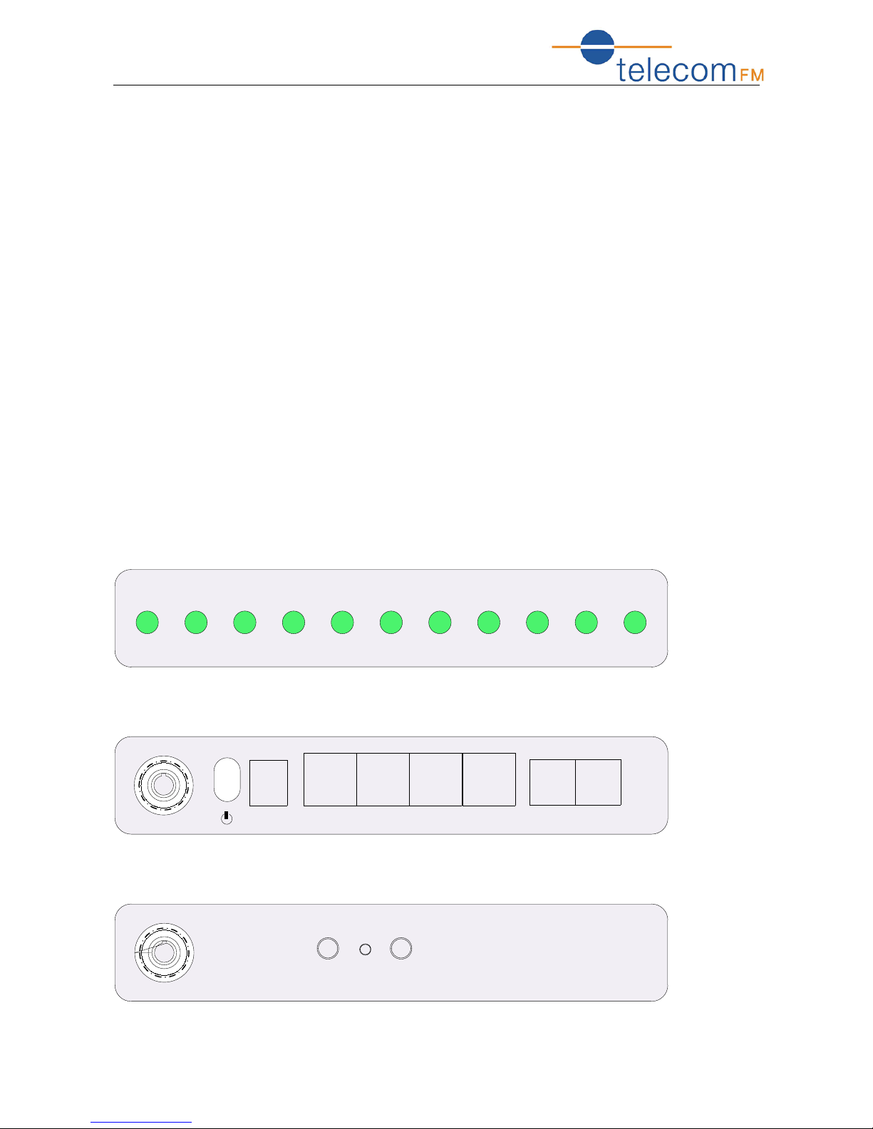
Indicators:
Power LAN 1 LAN 4
LAN 3LAN 2
I nternet DSL Wi Fi 3G VoI P
Interface 1:
Power
LAN 1 LAN 4LAN 3LAN 2 VoI P DSL
Interface 2:
WPSResetWi Fi
3
DataRoute voice User Manual
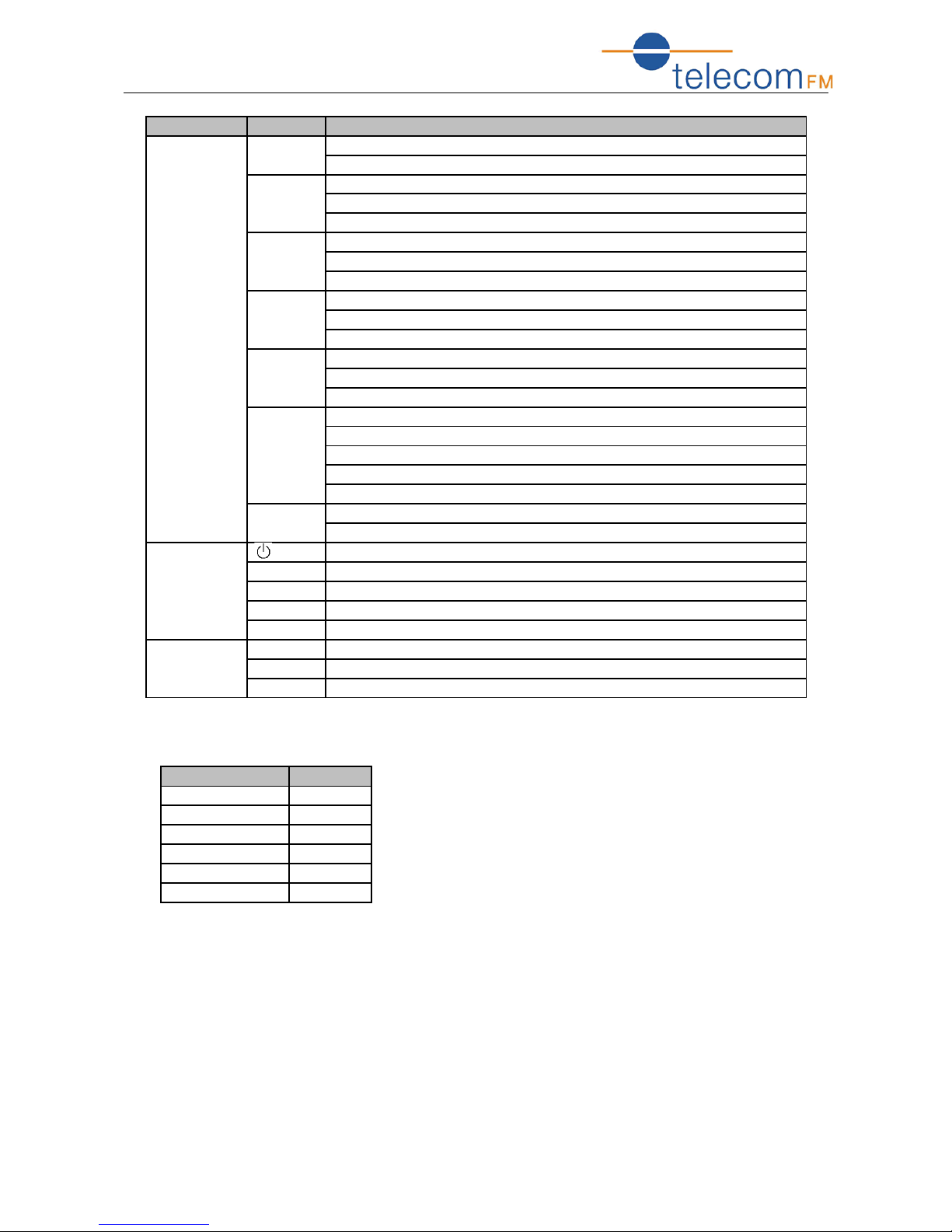
Item Label Description
Indicators Power On: Modem power up
Off: Modem Power off
LAN1-4 On: Ethernet is connected
Blinking green: Ethernet Traffic flows
Off: Ethernet is disconnected
Internet Blinking green: PPP/DHCP negotiation
Solid green: PPP/DHCP up
Quick blinking green: Tx/Rx traffic on line
DSL On: Modem synchronized to the DSLAM
Quick blinking green: Modem training, but not synchronized
Slow blinking green: Modem Idle
Wi-Fi On: Wi-Fi connection is available
Blinking green: Negotiation or traffic on line
Off: Wi-Fi connection is not available
3G Blinking green: Negotiation or traffic on line
Solid green: Up
Quick blinking green: Tx/Rx traffic on line
Solid red: Authentication failed
Off: Traffic through DSL interface
VoIP On: The analog phone connected to VoIP off-hook
Off: The analog phone connected to VoIP on-hook
Interface 1 Power switch
Power For 12V DC power adapter
LAN1-4 LAN interface for connecting to computers
VoIP Connecting to analog telephones
DSL Connecting to ADSL enabled telephone line
Interface 2 WiFi WiFi switch
WPS WPS switch
Reset Restore to factory default settings
2.1.2 Package Contents
Item Quantity
Power Adapter 1
Phone Line 2
RJ-45 Cable 1
Modem 1
User Manual 1
Splitter 1
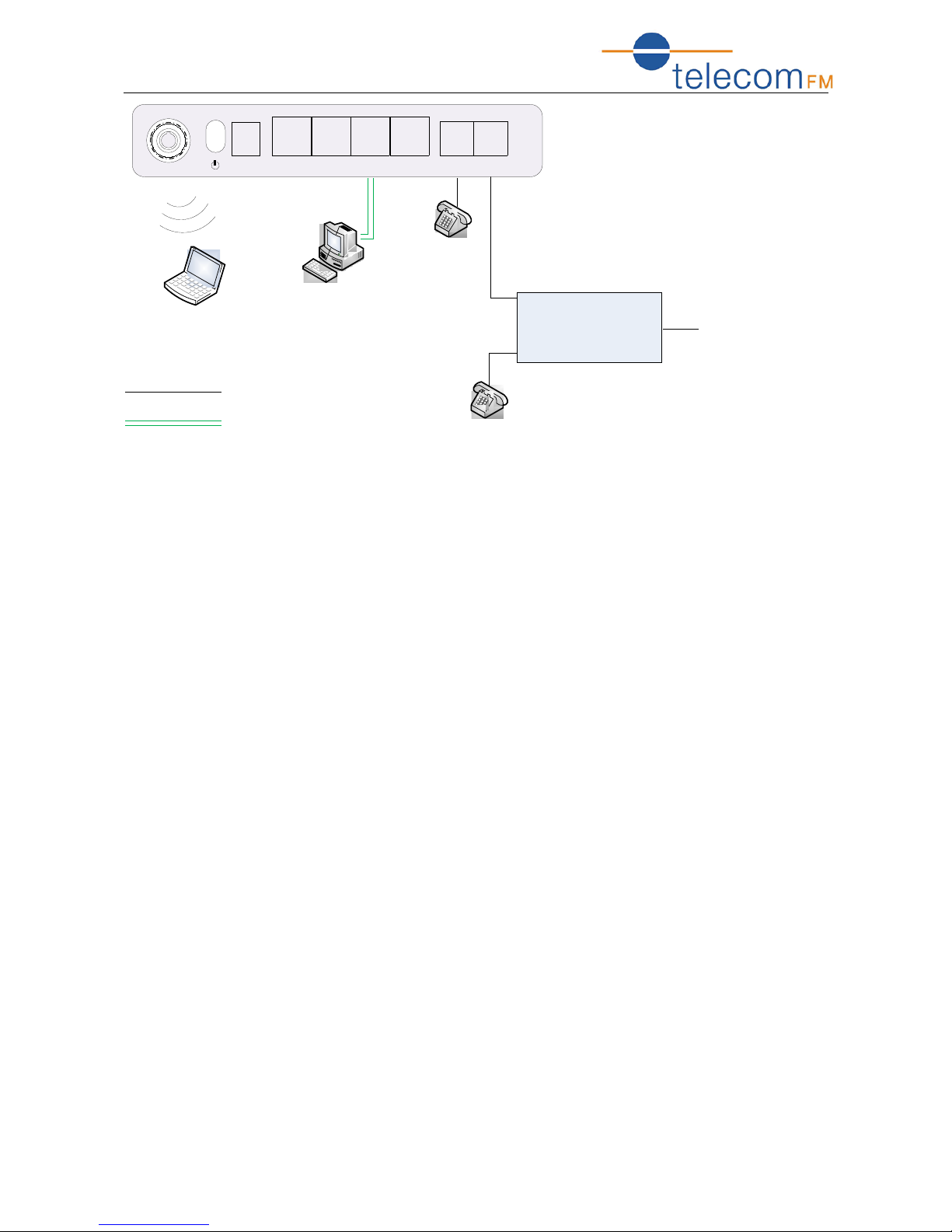
2.1.3 Connection Topological Diagram
4
DataRoute voice User Manual
Anal og Phone
Modem
Spl i tter
LI NE
Phone
LapTop
PC
Anal og Phone
RJ 45 Cable
RJ 11 Cable
DSL Li ne
W
i
-
F
i
Power
LAN 1 LAN 4LAN 3LAN 2 VoIP DSL
2.2 Hardware Connection
1.
Use a telephone cord to connect the LINE port of the splitter with the phone socket on
the wall (only if using ADSL).
2.
Use another telephone cord to connect the ADSL port of the splitter with the DSL port
of the DataRoute voice (only is using ADSL).
3.
Connect Ethernet port of the DataRoute voice with 10/100BASE-T port of the computer
using the network cable that comes with the unit.
4. Plug in the power cord, and turn on the power.
5

DataRoute voice User Manual
3. Configuration Guide
3.1 Default Configuration
The DataRoute voice is pre-configured with the common VCI/VPI settings. The default
dial-up mode is bridge encapsulation. For bridge mode, there is no need to configure any
more parameters. However, the third party dial-up software is needed for connection with
the Internet.
3.2 Computer Configuration
The default IP address for DataRoute voice is: 192.168.1.1; The Subnet Mask is
:
255.255.255.0. Users can configure the DataRoute voice through a web browser. The
DataRoute voice can be used as a gateway and DNS server; users need to set the
computer’s TCP/IP protocol as follow:
1.
Set the computer IP address to the same subnet as the DataRoute voice i.e. set the IP
address of the PC to one in the range of 192.168.1.2 - 192.168.1.254” excluding
192.168.1.1.
2.
Set the computer’s gateway address to the IP address of the DataRoute voice.
3.
Set the computer’s Primary DNS server to the IP address of the DataRoute voice or to
that of an effective DNS server.
6
DataRoute voice User Manual
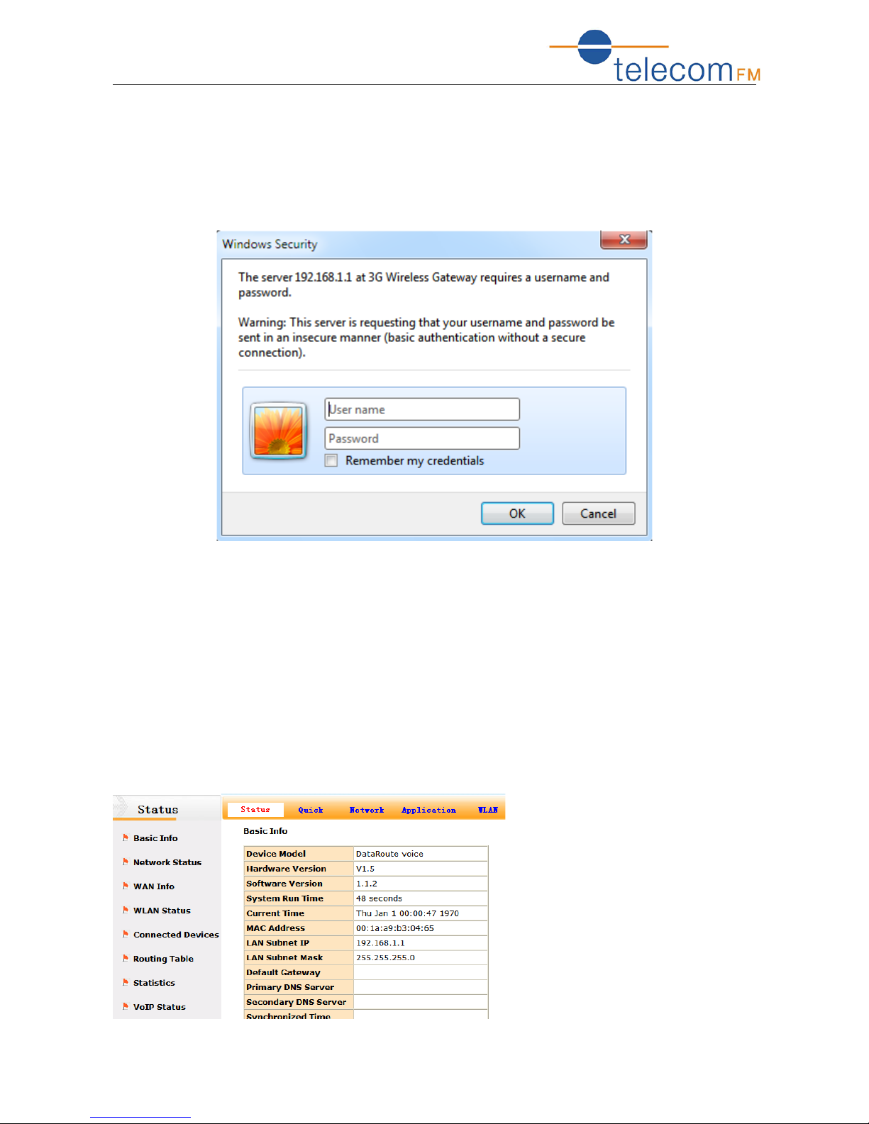
3.2.1 Log In
Power on to start the device, then make sure your computer can PING the DataRoute
voice (the factory default IP is 192.168.1.1), then run the web broswer. Enter
http://192.168.1.1 in the address bar, press ENTER, and the authentication interface
will pop up as below:
The default user name and password is admin for web log-on. Press ENTER or click
on ‘OK’ to enter the configuration interface.
Warning: Please be sure the IP of the computer network card is in the same IP range
as the DataRoute voice LAN port before trying to log on (ex: 192.168.1.2 and 192.168.1.1
are in the same IP range). If the login is not displayed please check in Internet Explorer-Tools---Internet Options---Connection---LAN Setup---Proxy server, disable the function
‘Proxy for LAN’ and then retry.
If log on successfull, the main page will be displayed as follows:
7
DataRoute voice User Manual
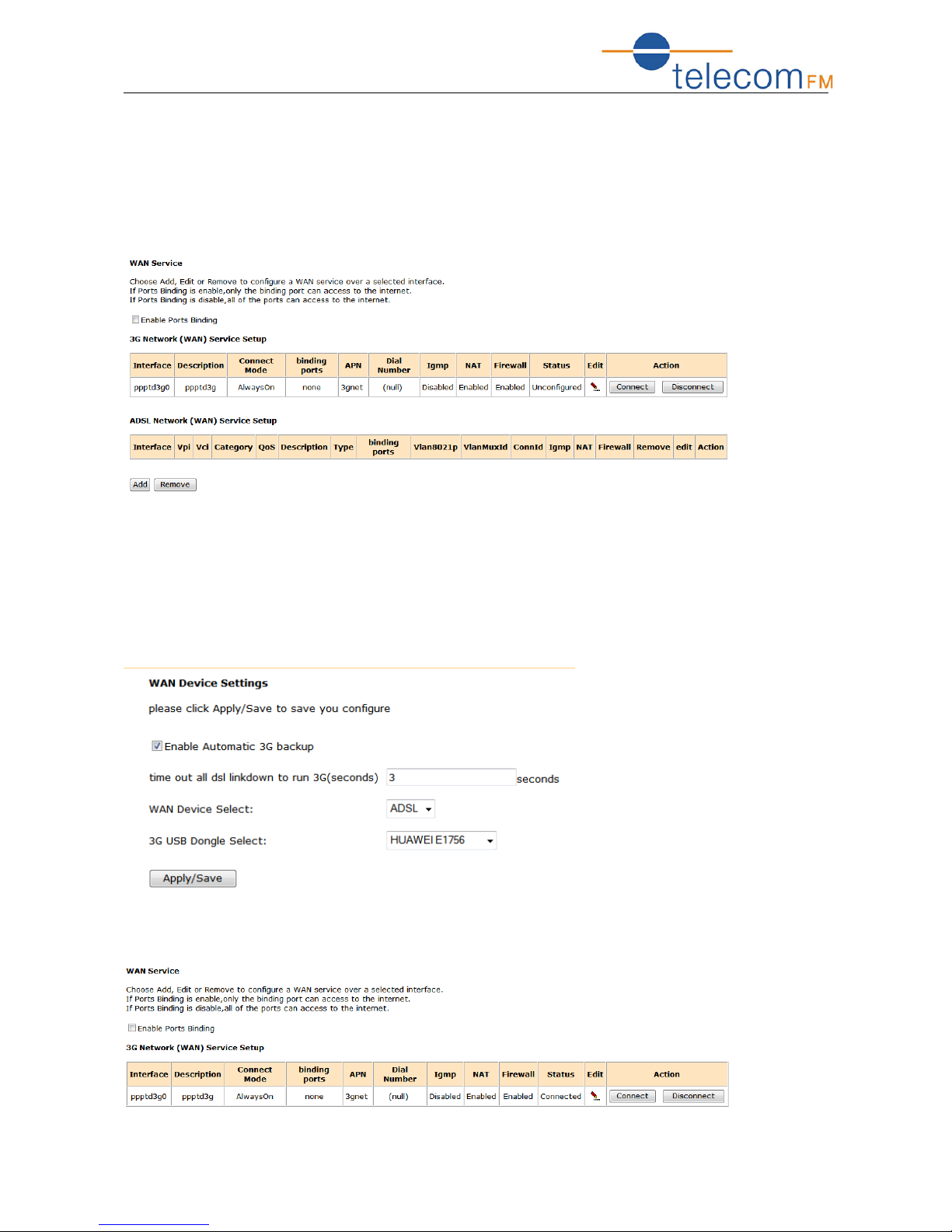
3.2.2 WAN Configuration
Please go to Network interface to select the WAN Service. Users can either edit a
3G network or an ADSL network.
Note: please power off the Gateway before inserting the SIM card.
3.2.2.1. 3G Network Service Setup
Please go to path: Network -> WAN Device page. Check the Enable Automatic 3G
backup, and configure the time out all DSL link down to run 3G – the value here is
used to determine the time interval for using 3G after DSL link is down. Then click
Apply/Save.
Then go to path: Network -> WAN Service to check the status. Please refer to the
following figure.
8
 Loading...