


Version 1.0
D myintercom Plus IP-Video Türstation Seite ...........3
GB myintercom Plus IP video door station Page ........... 43
Anleitung myintercom Plus IP-Video Türstation
D
Wichtige Hinweise
Wichtige Hinweise
Bitte beachten Sie, dass Behnke Sprechstellen und Zubehörteile ausschließlich von
Elektrofachkräften unter Einhaltung der
entsprechenden Sicherheitsbestimmungen
installiert und gewartet werden dürfen.
KONTAK T
Info-Hotline
Ausführliche Informationen zu Produkten,
Projekten und unseren Dienstleistungen:
Tel.: +49 (0) 68 41 / 81 77-700
24 h Service-Hotline
Sie brauchen Hilfe? Wir sind 24 Stunden
für Sie da und beraten Sie in allen tech nischen Fragen und geben Starthilfen:
Tel.: +49 (0) 68 41 / 81 77-777
Achten Sie bitte darauf, dass die Geräte
vor Wartungs- oder Reparaturarbeiten vom
Stromnetz (Steckernetzteil) und vom Netzwerk getrennt sind.
Weitere rechtliche Hinweise finden Sie auf
Seite 39.
Telecom Behnke GmbH
Gewerbepark „An der Autobahn“
Robert-Jungk-Straße 3
66459 Kirkel
E-Mail- und Internet-Adresse
info@behnke-online.de
www.behnke-online.de
2 www.behnke-online.de

Anleitung myintercom Plus IP-Video Türstation
Inhalt
INHALT
1. Einleitung 4
1.1. Lieferumfang ................................................................................................................... 4
1.2. Allgemein ....................................................................................................................... 4
1.3. Die myintercom Plus IP-Video Türstation ........................................................................ 6
1.4. Empfohlene Montage-Position ........................................................................................ 7
1.5. Lichtverhältnisse ............................................................................................................ 7
1.6. Beschriftungsfelder wechseln ........................................................................................ 7
1.7. Türstation anbringen .......................................................................................................8
1.8. Einsatzszenarien ............................................................................................................9
2. Installation 12
2.1. POE ................................................................................................................................14
2.2. Zweidrahttechnik ..........................................................................................................14
2.3. Türöffner/ Relais/Gong ................................................................................................15
2.4. Türgong einstellen ........................................................................................................16
3. Zusatzmodule 17
3.1. Sicherheitsrelais ............................................................................................................17
D
4. Kartenleser 20
4.1. Speicherplatz auswählen ...............................................................................................21
4.2. Transponder ..................................................................................................................21
4.3. Türöffnerzeit konfigurieren .......................................................................................... 22
4.4. Zweite Masterkarte ...................................................................................................... 23
5. Konfiguration 25
5.1. Starten der App „myintercom“ ...................................................................................... 25
5.2. Übersicht ...................................................................................................................... 25
5.3. Administration der Video-Türstation ............................................................................. 27
5.4. Verwalten von Video-Türstationen ................................................................................ 30
5.5. Bedienung der App ........................................................................................................ 32
6. Technische Merkmale 34
7. Fehlerbehebung 36
8. Bemaßung 37
9. Rechtliche Hinweise 39
3www.behnke-online.de

Anleitung myintercom Plus IP-Video Türstation
D
Einleitung
. EINLEITUNG
1.1. Lieferumfang
myintercom Plus IP-Video Türstation
▸
Bedienungsanleitung
▸
Beiblatt „Einrichtung“
▸
Bei Ausführung mit Zweidrahttechnik:
▸
• 2 Koaxialadapter
• 2-Draht Empfänger zur Montage im
geschützten Innenbereich
1.2. Allgemein
Leistungsmerkmale
Bei der myintercom IP-Video Türstation
handelt es sich um ein Kompaktgerät mit integrierter Kamera, Lautsprecher und Mikrofon.
Die bis zu drei Ruftasten sind mit beleuchteten Beschriftungsfeldern ausgestattet.
Der integrierte Sabotagekontakt erfüllt
zusammen mit einem separat erhältlichen,
abgesetzten Sicherheitsrelais erhöhte
Anforderungen an Sicherheit und Komfort.
für die myintercom IP-Video Türstation. Der
Nutzer sieht mit dem Smartphone oder Tablet,
wer vor der Tür steht, spricht mit ihm oder ihr
und öffnet bei Bedarf per Knopfdruck von dem
Smartphone oder Tablet aus die Tür. Hierzu ist
das Smartphone oder das Tablet im lokalen
WLAN eingebucht.
Um das Gespräch von der Tür auch unterwegs
annehmen zu können, ist die Freischaltung
der Video-Türstation über
www.myintercom.de/activate erforderlich.
Die Bild- und Tonübertragung erfolgt dann
via Inter net (WL AN / 3G / LTE ). Be i sc hlechten
Lichtverhältnissen kann die in der VideoTürstation vorhandene Beleuchtung während
des Gespräches vom Smartphone oder Tablet
aus aktiviert werden.
Durch die integrierte Echounterdrückung
ist eine Voll-Duplex Sprachverbindung vom
Smartphone oder Tablet zur Tür gegeben.
Damit kein Anruf von der Tür verloren geht,
werden die letzten 20 Ereignisse mit Kamerabild und Uhrzeit in der Türstation gespeicher t.
Die myintercom Technik ermöglicht es die vorhandene Infrastruktur auch zur Video-Türkommunikation zu nutzen. Mit myintercom wird
das Smartphone oder Tablet zur Gegenstelle
4 www.behnke-online.de

Anleitung myintercom Plus IP-Video Türstation
Einleitung
D
Systemvoraussetzungen
Zur Nutzung der myintercom IP-Video
Türstation sind folgende Mindestvoraussetzungen erforderlich:
Variante Zweidrahttechnik: Zweiadriges
▸
Telekommunikationskabel
Variante Ethernet: PoE (nach IEEE
▸
802.af-2003) gespeistes Cat5 EthernetKabel
Freier Netzwerk-Port am Switch/Router
▸
WLAN
▸
Die myintercom App aus dem Apple
▸
AppStore bzw. Google PlayStore
DHCP-Server, der eine IP-Adresse, Subnetz-
▸
maske, Gateway und DNS-Server vergibt
(Standard)
Optional, sofern auf die Türstation auch
▸
außerhalb des LAN, z.B. von unterwegs über
Internet, zugegriffen werden soll: Festnetz
Breitbandinternetverbindung (ohne Proxy-/
Socksserver) über einen Internetanbieter,
z. B. DSL 2000 oder schneller. Flatrate
(Datenvolumen) empfohlen. Die Türstation
muss eine direkte Verbindung ins Internet
aufbauen können (ohne Proxy- /Socksserver).
iOS 5 und neuer – iPhone4S, iPhone5, iPad
▸
mit aktivier ter Apple-ID zum Download der
kostenfreien App
Android 4 und neuer – Smartphones und
▸
Tablets (mind. Dual Core-Prozessor 2 x 1,2
GHz oder schneller) und aktiviertem Google
Play Konto zum Download der kostenfreien
App
Achtung: Bitte bewahren Sie das Beiblatt
„Einrichtung“ sorgfältig auf. Ohne die darauf
abgedruckten Zugangsdaten ist eine spätere
Änderung der Konfiguration nicht möglich.
5www.behnke-online.de
Anleitung myintercom Plus IP-Video Türstation
D
Einleitung
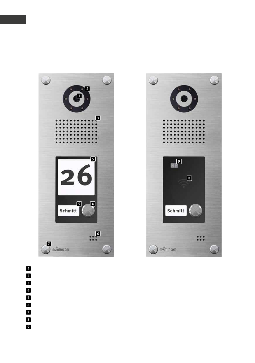
1.3. Die myintercom Plus IP-Video Türstation
5
5
Kamera
Beleuchtungsring
Lautsprecher
Ruftaste
Beschriftungsfeld
Mikrofon
Schraubenabdeckung
Kartenleser
Kartenleseranzeige
6 www.behnke-online.de
Anleitung myintercom Plus IP-Video Türstation
Inbetriebnahme
D
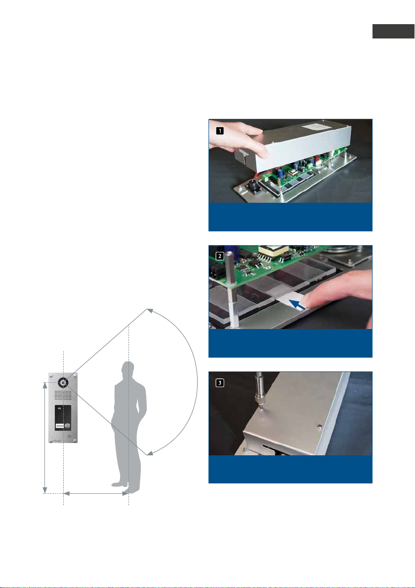
1.4. Empfohlene Montage-Position
Für einen optimalen Blickwinkel der Kamera,
wird eine Installationshöhe von 155 cm empfohlen. Weitere Einzelheiten entnehmen Sie
bitte der Abbildung.
1.5. Lichtverhältnisse
Um eine bessere Bildqualität bei schlechten
Lichtverhältnissen oder nachts zu erhalten,
wird eine Außenbeleuchtung empfohlen.
1.6. Beschriftungsfelder wechseln
1
Um die Beschriftungsfelder zu wechseln, nehmen Sie
zuers t den Gehäusedeckel de r Türs tation ab.
Schieb en Sie danach den Papierstreifen in die dafür
vorgesehene Öffnung des Beschriftungsfeldes.
155 cm
50 cm
Schrauben Sie danach den Gehäusedeckel wieder
an – fer tig.
7www.behnke-online.de
Anleitung myintercom Plus IP-Video Türstation
D
Inbetriebnahme
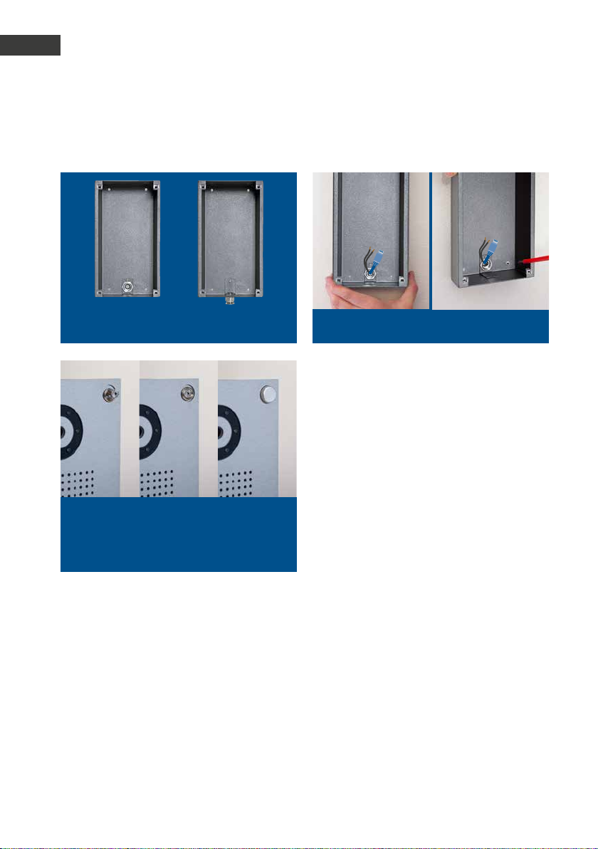
1.7. Türstation anbringen
Gehäuse anbringen un d die Türstation anschließenAufputzgehäuse für Kabelzuführung vorbereiten
Türs tation ins Gehäuse einsetzen und mit vier
Schrauben mit dem Auf putzgehäuse ver schrauben.
Danach die Schraubenabdeckungen aufschrauben
- fertig!
Das Beispiel zeigt die Montage der Aufputzvariante. Die Türstation kann alternativ auch
Unterputz montiert werden. Hierfür wird das
passende Unterputzgehäuse in die Wandöffnung oder den Hohlwandausschnitt montiert und die Türstation wie gezeigt befestigt.
8 www.behnke-online.de
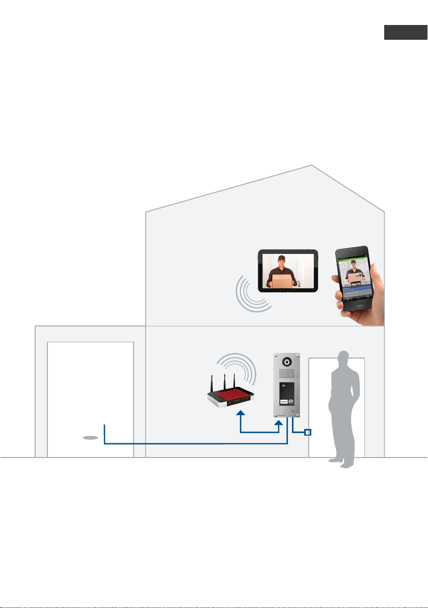
1.8. Einsatzszenarien
Lokal
Die Graf ik zeig t die Verwendung innerhalb
eines Wohn- oder Bürogebäudes mit Zugriff
über das lokale WLAN.
Anleitung myintercom Plus IP-Video Türstation
Inbetriebnahme
D
Zusatzrelais
(Garage)
Büro-Etage
Foyer
DSL-Router / Switch
WLAN
WLAN
Tablet / Smartphone
myintercom Plus VideoTürstation mit Kamera
Ethernet
Türöffner
9www.behnke-online.de
Anleitung myintercom Plus IP-Video Türstation
D
Einleitung
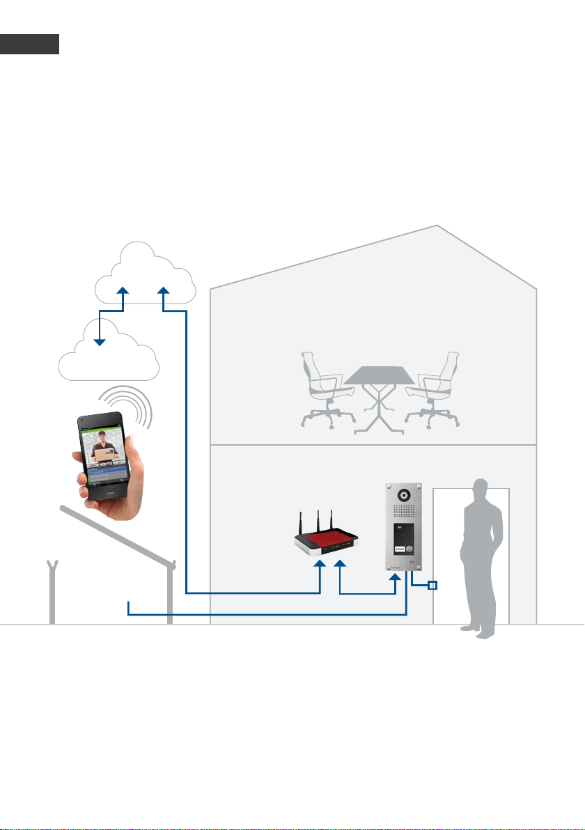
Global
Die Graf ik zeig t die Verwendung außerhalb
eines Wohn- oder Bürogebäudes mit Zugriff
via Internet.
INTERNET
Büro-Etage
WLAN / 3G / LTE
Sprache,
Bild
Foyer
myintercom Plus VideoTürstation mit Kamera
DSL-Router / Switch
Zusatzrelais
(Schranke)
Ethernet
Türöff ner
10 www.behnke-online.de
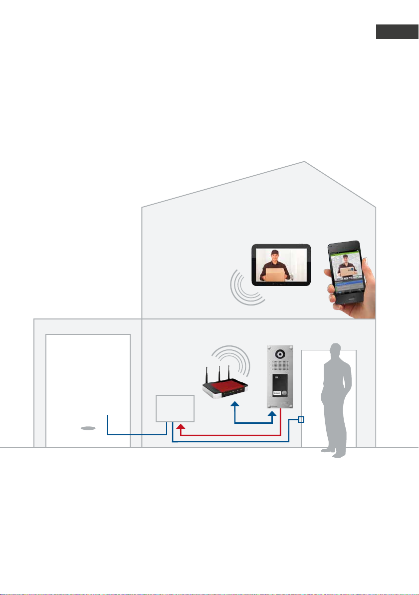
Lokal oder Global (mit Sicherheitsrelais)
Die Graf ik zeig t die Verwendung innerhalb
eines Wohn- oder Bürogebäudes mit innenliegendem Sicherheitsrelais.
Anleitung myintercom Plus IP-Video Türstation
Einleitung
D
Büro-Etage
Foyer
DSL-Router / Switch
Zusatzrelais
(Garage)
Sicherheitsrelais:
Sicherheit durch Montage im sabotage-
▸
geschützten Innenbereich
Verbunden mit myintercom Plus IP-Video
▸
Türstation
Sicherheits-
relais
Tablet / Smartphone
WLAN
myintercom Plus Video-
WLAN
sichere Kommunikation
Kommunikation zwischen Sicherheitsrelais
▸
Türstation mit Kamera
Ethernet
Türöff ner
und Türstation über gesichertes Protokoll
Stellt zwei potentialfreie Relaiskontakte zur
▸
Verfügung
11www.behnke-online.de
Anleitung myintercom Plus IP-Video Türstation
D
Installation
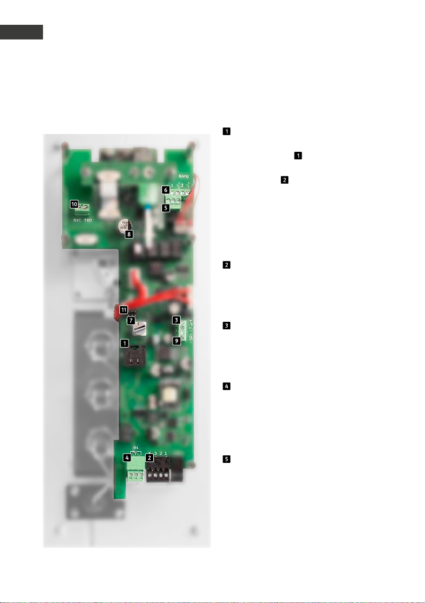
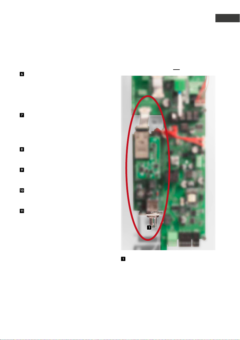
. INSTALLATION
Elektronik der Türstation
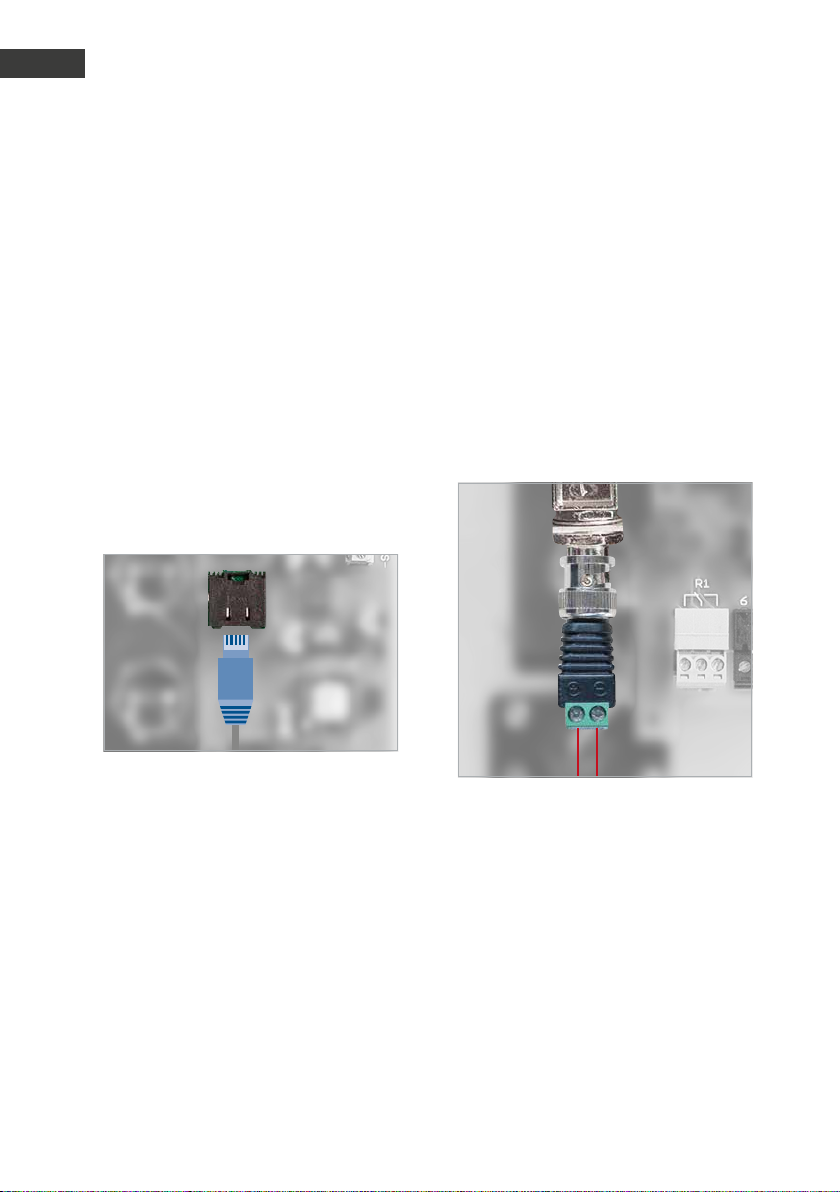
Ethernetbuchse
Der LAN-Anschluss erfolgt üblicherweise über
einen RJ-45 Stecker . Alternativ lassen sich
die einzelnen Adern aber auch via Klemmleiste anbinden : Das Netzwerk wird auf
die mit 1 (orange-weiß), 2 (orange) 3 (grünweiß) und 6 (grün) bezeichneten Klemmen
nach EIA/TIA 568 B angeschlossen. Die Zahl
bezeichnet die Pin-Nummer des RJ-45 Steckers/der RJ-45 Dose.
Alternativer Ethernetanschluss
Ein gleichzeitiger Anschluss von Buchse und
Schraubklemmen ist nicht zulässig! Dies kann
zu einem Defekt der Türstation führen!
Türöffneranschluss
Anschlussmöglichkeit für einen Türöffner
(12 V max. 9 W). Siehe Kapitel 2.4 Türöffner/
Relais / Gong.
Relais 1 (Türöffnerrelais)
Potentialfreier Anschluss (belastbar mit
30 VDC /max. 1 A) für einen Türöffner, der
durch die App „myintercom“ aktivier t wird.
Siehe Kapitel 2.4 Türöffner /Relais /Gong.
Relais 2 (Zusatzrelais)
Potentialfreier Anschluss (belastbar mit
30 VDC /max. 1 A), welcher durch die App
„myintercom“ aktivierbar ist. Siehe Kapitel
2.4 Türöffner /Relais / Gong.
12 www.behnke-online.de
Gonganschlüsse
Potentialfreie Anschlüsse für drei Türgongs
(belastbar mit 30VDC /max. 1A), die bei
Tastendruck aktiviert werden. Siehe Kapitel
2.4 Türöffner /Relais / Gong.
Gongschalter
Mit Hilfe des Gongschalters kann die Anzahl
der Gongschläge bei Tastendruck eingestellt
werden. Siehe Kapitel 2.5 Türgong einstellen.
Sabotagekontakt
Siehe Kapitel 1.2 Allgemein.
Versorgungsbuchse des Sicherheitsrelais
Siehe Kapitel 3.1 Sicherheitsrelais.
Anleitung myintercom Plus IP-Video Türstation
Installation
Elektronik der Türstation mit Zweidrahttechnik
D
Anschlussbuchse für Sicherheitsrelais
Siehe Kapitel 3.1 Sicherheitsrelais.
Anschluss für Türöffnertaster
Siehe Kapitel 2.4 Türöffner /Relais /Gong.
Anschlussbuchse für Koaxialkabel
Datenübertragungs- und Versorgungsmöglichkeit für die myintercom Plus Video-Türstation. Siehe Kapitel 2-Drahtrahttechnik auf
Seite 14.
Achtung: Eine gleichzeitige Nutzung von
2-Draht Über trager und Ethernet ist nicht
zulässig.
13www.behnke-online.de
Anleitung myintercom Plus IP-Video Türstation
D
Installation
Die myintercom Plus IP-Video Türstation
bietet mehrere Optionen die Türstation und
die Zusatzmodule mit Energie zu versorgen.
2.1. POE
Diese Möglichkeit kann genutzt werden, sobald ein PoE-fähiger Router oder Switch bzw.
ein PoE-Injektor (nach IEEE 802.3af-2003)
vorhanden ist.
Zum Anschließen der Türstation bitte den
Gehäusedeckel abnehmen und das Patchkabel in die dafür vorgesehene RJ45 Buchse
stecken.
2.2. Zweidrahttechnik
Eine weitere Option die Türstation zu versorgen, besteht in der Verwendung des
Zusatzmoduls 2-Draht Übertrager. Nehmen
Sie den Gehäusedeckel der Türstation ab und
schließen Sie ein Koaxialkabel an die dafür
vorgesehene Buchse am Zweidrahtsender an.
Falls Sie kein Koaxialkabel, sondern lediglich
zwei Adern zur Verfügung haben, verwenden
Sie bitte den beiliegenden Koaxialkabeladapter.
Wichtig! Damit der Sabotageschutz wirksam
wird, muss der Gehäusedeckel wieder angeschraubt werden!
14 www.behnke-online.de
Wichtig! Damit der Sabotageschutz wirksam
wird, muss der Gehäusedeckel wieder angeschraubt werden!
Das zweite Ende des Koaxialkabels wird an
den Zweidrahtempfänger angeschlossen.
Speisen Sie PoE über das Patchkabel ein, das
in die RJ45 Buchse des Zweidrahtempfänger
gesteckt wird. Verwenden Sie dazu bitte einen
PoE-Injektor bzw. einen PoE-fähigen Router
oder Switch nach dem IEEE 802.at Standard.
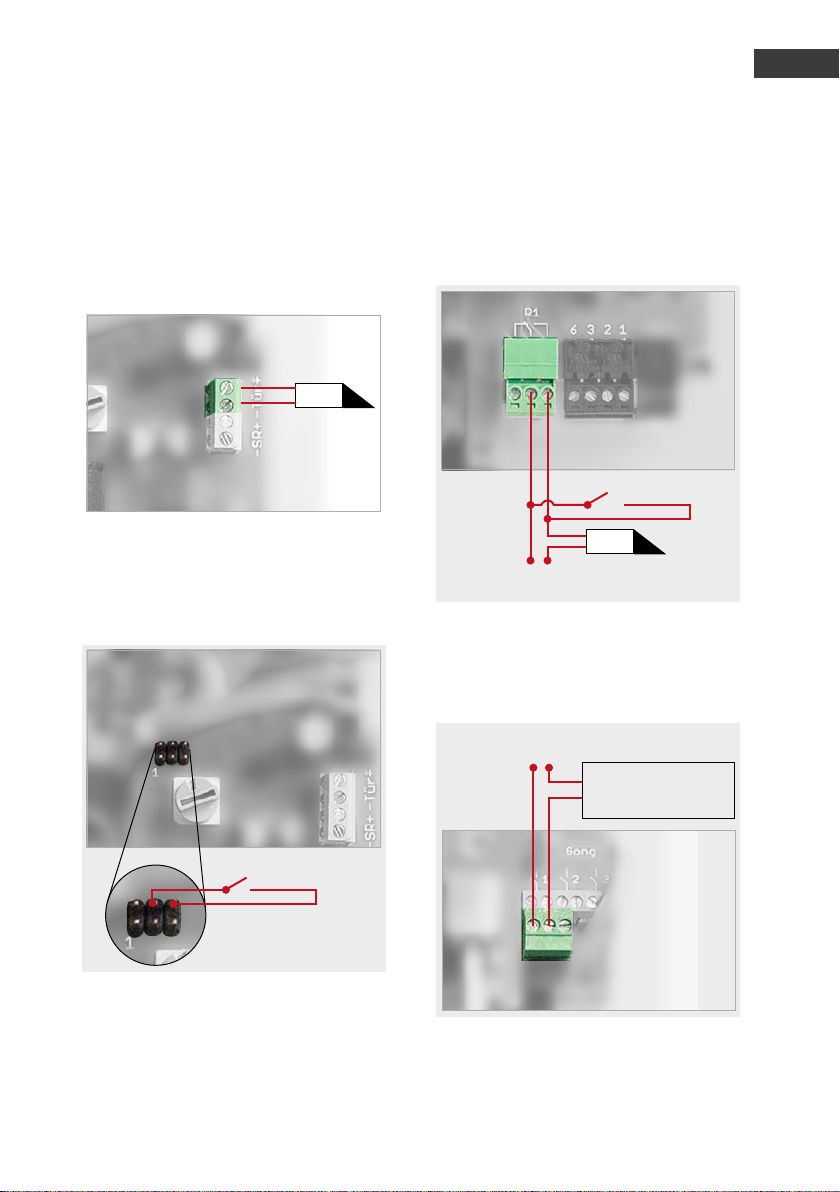
2.3. Türöffner/ Relais/Gong
Nehmen Sie den Gehäusedeckel der Türstation ab und schließen Sie die Komponenten
wie folgt an:
TÖ
Anleitung myintercom Plus IP-Video Türstation
Installation
Relais 1 steht an der Klemme mit der Bezeichnung „R1“ und Relais 2 steht an der Klemme
mit der Bezeichnung „R2“ zur Verfügung.
Optionale ex terne Türöffner taste (bauseits)
D
Der Türöffner, den die Türstation direkt
betreibt (12 V DC / AC max. 9 W ), wird an die
Anschlussklemme mit der Bezeichnung „Tür“
angeschlossen.
Optionale ex terne Türöffner taste (bauseits)
Wird der Türöffner direkt über die Türstation
versorgt, so kann ein externer Türöffnertaster
angeschlossen werden, um die Tür zu öffnen.
TÖ
Externe s Türöff ner Netzte il
(siehe te chn. Merkmale)
Anschluss Relais 1
Hinweis: Die Türöffnerspannung und das
Relais 1 werden immer parallel geschaltet.
Exter nes Netzteil
(siehe te chn. Merkmale)
Beleuchtungsteuerung,
Garagentoröffner,
Schrankensteuer ung, ...
Anschluss Relais 2
15www.behnke-online.de
Anleitung myintercom Plus IP-Video Türstation
D
Installation
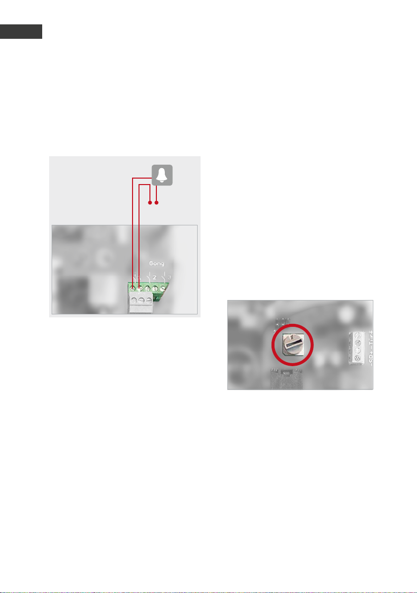
Die Türgongs werden an die Anschlussklemmen mit der Bezeichnung „Gong“ angeschlossen. Taste 1 schaltet Gong 1, Taste 2 schaltet
Gong 2,… Die Tasten sind von oben nach unten
nummeriert.
Gong 1
(bauseits)
Klingeltraf o
(bauseits)
Wichtig! Damit der Sabotageschutz wirksam
wird, muss der Gehäusedeckel wieder angeschraubt werden!
2.4. Türgong einstellen
Die Anzahl der pro Tastendruck an der Türstation ausgelösten Gongschläge kann eingestellt werden. In der Grundeinstellung schaltet
die Station bei einem Tastendruck den Gong
zweimal an und wieder aus (Schalterstellung 2). Mit Hilfe eines Drehschalters auf der
Elektronik der Türstation kann die Anzahl zwischen Null und Neun variiert werden. Bei der
Schalterstellung Null ertönt kein Gong mehr,
es erscheint lediglich eine Push Meldung auf
dem Endgerät.
Um den Drehschalter einzustellen, nehmen
Sie den Gehäusedeckel ab und stellen den
Schalter auf die gewünschte Zahl.
Wichtig! Damit der Sabotageschutz wirksam
wird, muss der Gehäusedeckel wieder angeschraubt werden!
16 www.behnke-online.de
. ZUSATZMODULE
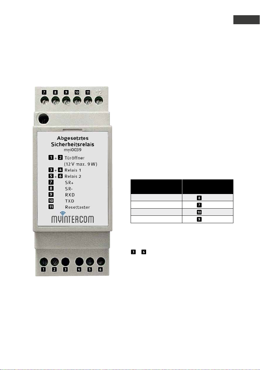
3.1. Sicherheitsrelais
Anleitung myintercom Plus IP-Video Türstation
Zusatzmodule
Dieses Modul bietet weitergehende Sicherheitsmaßnahmen, indem es den Türöffner und
die beiden Relais in den geschützten Innenbereich des Hauses verlagert.
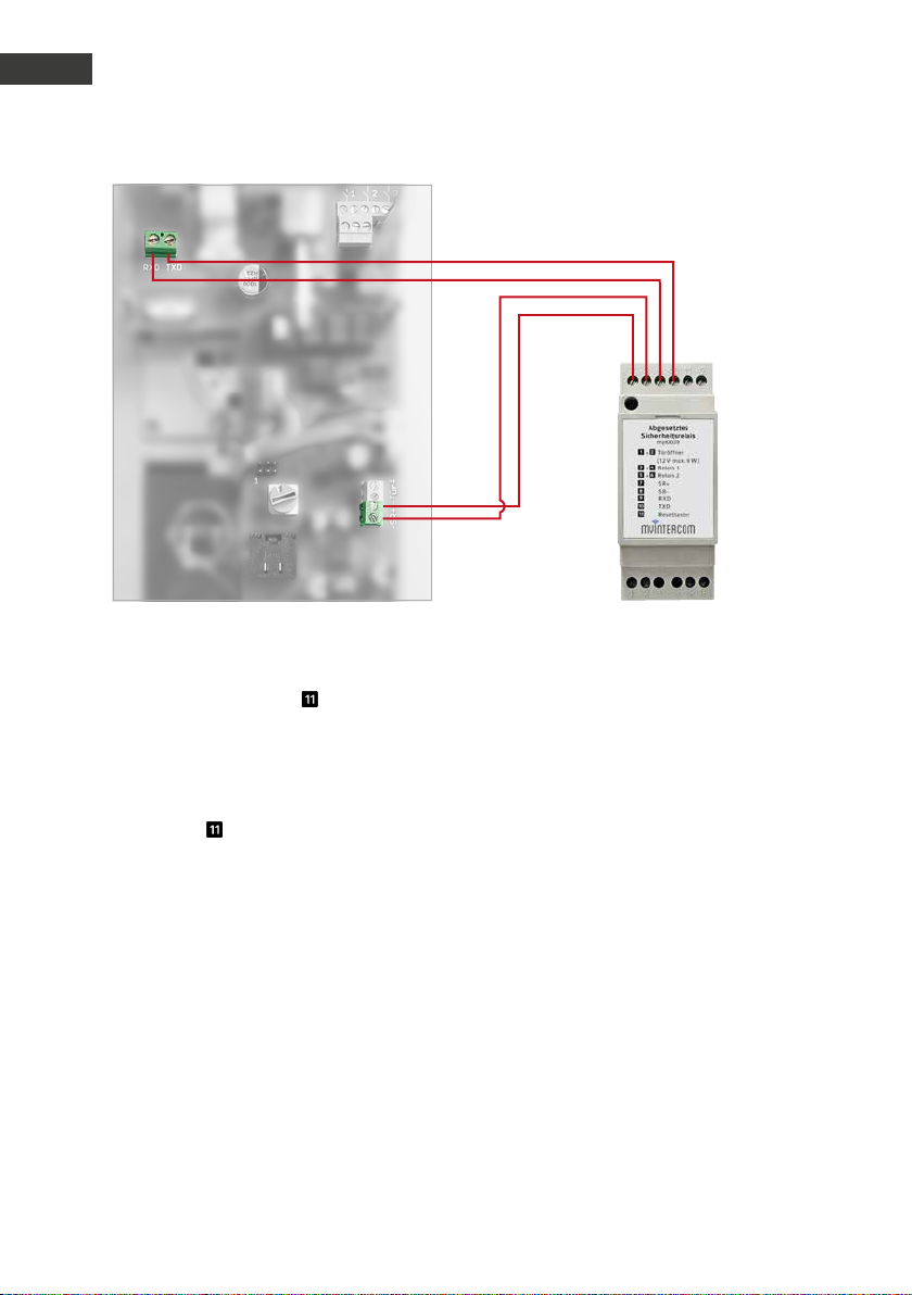
Das Sicherheitsrelais wird mit vier Adern an
die Türstation angeschlossen und durch diese
auch mit Energie versorgt.
Verbinden Sie folgende Anschlussklemmen
der Türstation mit den Klemmen des Sicherheitsrelais:
D
Kennzeichnung an
der Türstation
SR- SRSR+ SR+
TXD TXD
RXD RXD
– Schließer, bel. 30 VDC max. 1 A
Potentialfreier Kontakt, separate Stromversorgung für das angeschlossene Gerät erforderlich.
Kennzeichnung am
Sicherheitsrelais
17www.behnke-online.de
Anleitung myintercom Plus IP-Video Türstation
D
Zusatzmodule
Mit Hilfe des Resettasters wird ein Reset
der Türstation durchgeführt, wenn der
Sabotagekontakt ausgelöst hat. Stellen Sie
dazu sicher, dass der Gehäusedeckel der
IP-Türstation angeschraubt ist und drücken
Ebenfalls besteht die Möglichkeit bei diesem
Zusatzmodul ein zweites Zusatzrelais zu nutzen. Darüber kann beispielsweise ein Garagentoröffner, ein zweiter Türöf fner, eine Schranke
oder die Außenbeleuchtung gesteuert werden.
Sie den Taster auf dem Sicherheitsrelais für
mindestens 2 Sekunden.
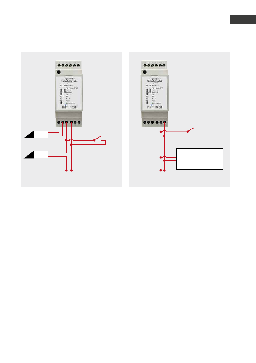
An die Klemmen des Sicherheitsrelais mit
der Beschriftung „Türöffner“ kann direkt ein
Türöf fner (12 V DC /AC max. 9 W) angeschlossen werden. Optional kann dieser auch mit
einer externen Stromversorgung an Relais 1
betrieben werden. Es ist zu beachten, dass
die Türöffnerspannung und das Relais 1 immer
gleichzeitig geschaltet werden.
18 www.behnke-online.de
Anleitung myintercom Plus IP-Video Türstation
Zusatzmodule
D
TÖ
TÖ
Externe s Türöff ner Netzte il
(siehe te chn. Merkmale)
Optionale ex t. Türöffner taste (bauseits)
Exter nes Netzteil
(siehe te chn. Merkmale)
Optionale ex t. Bestät igungstaste (bau seits)
Beleuchtungsteuerung,
Garagentoröffner,
zweiter Türöffner,
Schrankensteuer ung, ...
Relais 1 und Türöffner Relais 2
Wichtig! Bitte beachten Sie, dass die myintercom Plus IP-Video Türstation lediglich einen
Türöf fner direkt betreiben kann. Dieser darf nur am Sicherheitsrelais oder nur an der Türstation
angeschlossen werden.
Hinweis: Das Sicherheitsrelais stellt keine separat ansteuerbaren Relais bereit, es ersetzt
Relais 1 und 2, sowie die Türöffnerspannung der Türstation.
19www.behnke-online.de
Anleitung myintercom Plus IP-Video Türstation
D
Kartenleser
. KARTENLESER
Es besteht die Möglichkeit die myintercom
Plus IP-Video Türstation mit einem integrierten Kartenleser zu erwerben. So kann eine
einfache Zugangskontrolle realisiert werden,
indem alle berechtigten Personen eine RFID
Karte erhalten, die an der Türstation registrier t
werden. Durch Anhalten einer registrierten
Karte an den Kar tenleser schaltet das Relais 1
und der Türöffner.
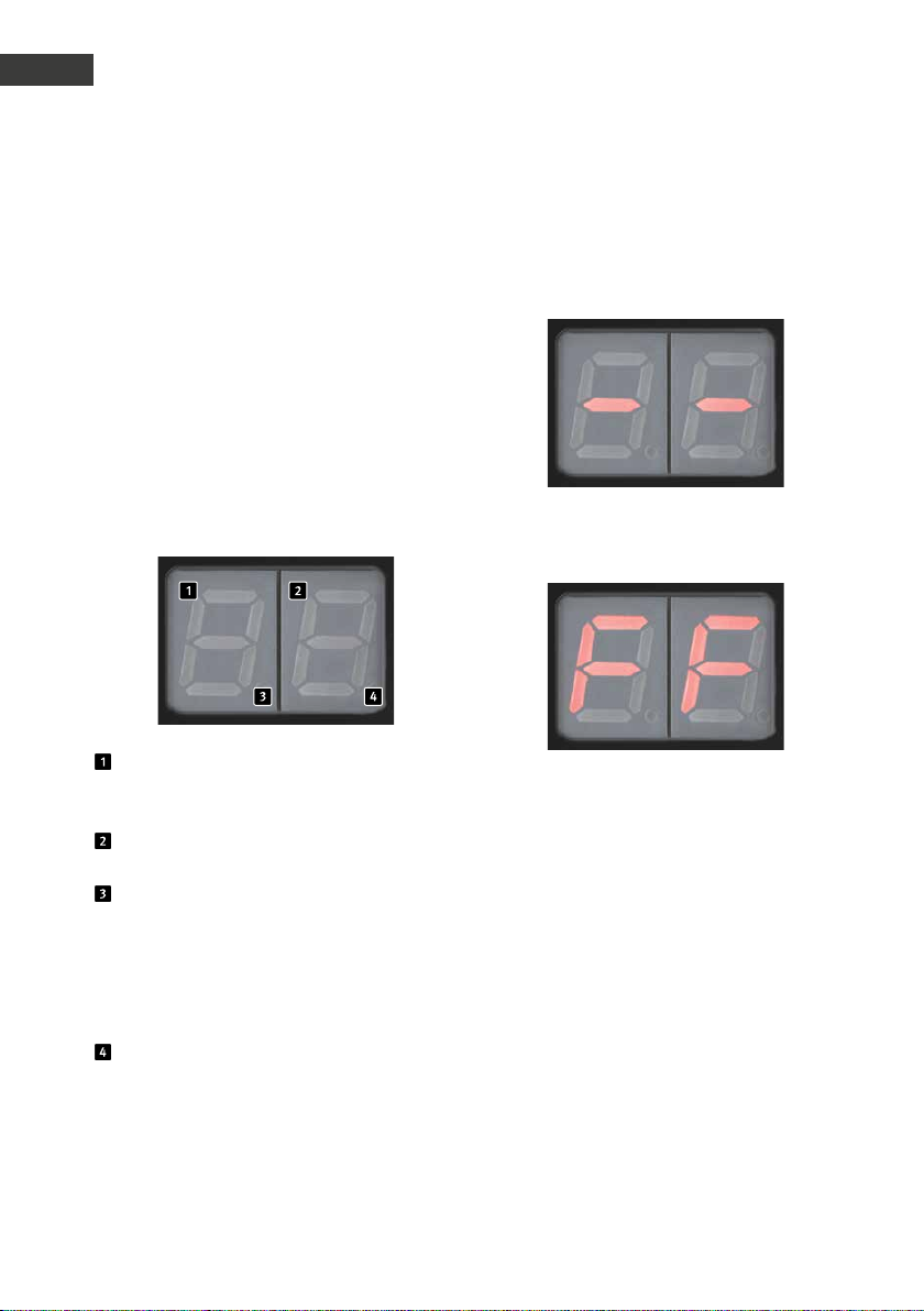
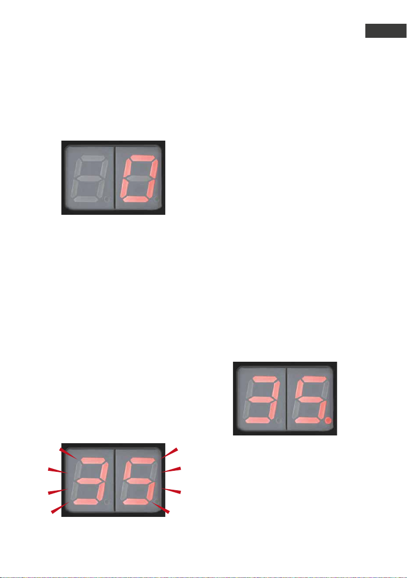
Übersicht Display
Anzeige der 10er-Stellen des aktuellen
Speicherplatzes (10; 20; 30; ... 90; 1.1;
1.2; 1.3; ... 9.9)
Anzeige der 1er-Stellen des aktuellen
Speicherplatzes (Von 0 bis 9 )
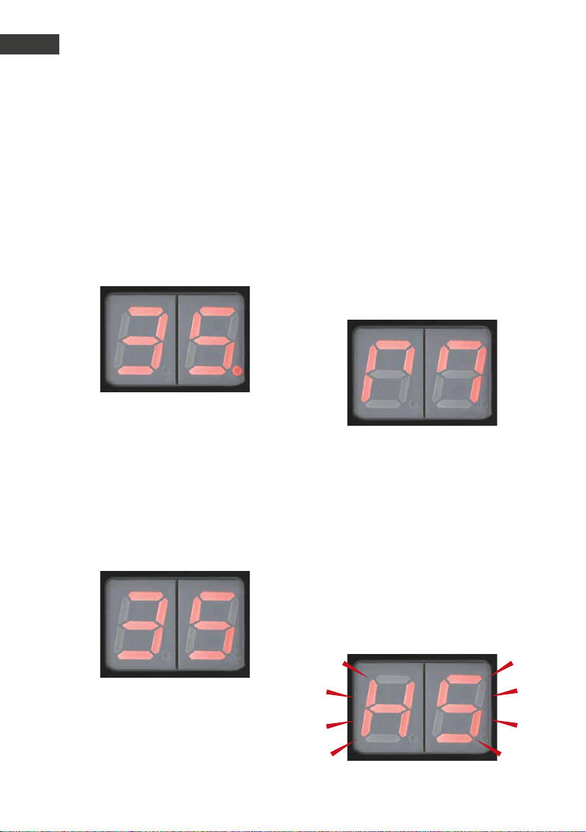
Dieser Dezimalpunkt symbolisiert die
100er-Stelle. Ab dem Speicherplatz 100
leuchtet der linke Dezimalpunkt (z.B. „5.3 “
für 153) Bei den Speicherplätzen von 0 bis
99 leuchtet der Dezimalpunkt nicht.
(z.B. „5 3“ für 53)
Dieser Dezimalpunkt zeigt an, ob der
aktuelle Speicherplatz belegt ist.
(z.B. „3.8.“ : der Speicherplatz 138 ist
durch einen Transponder beleg t).
Wenn die Anzeige blinkt, können Änderungen
vorgenommen werden.
Weitere Betriebsanzeigen:
Der im Erfassungsbereich befindliche Trans-
ponder wurde noch nicht programmier t.
Fehlfunktion!
Der Kar tenleser arbeitet nicht einwandfrei, es
liegt ein interner Fehler vor. Bitte schicken Sie
die Türstation zur Reparatur.
20 www.behnke-online.de
Anleitung myintercom Plus IP-Video Türstation
Kartenleser
D
4.1. Speicherplatz auswählen
Halten Sie die Masterkarte vor den Kartenleser. Die Anzeige schaltet sich ein:
Die Speicherplätze werden von 0 bis 10 in 1er
Schritten angezeigt. (00...01...02...03...)
Ab dem 10. Speicherplatz wird in 10er Schritten (Schnellmodus) weitergezählt.
Um wieder in 1er Schritten zu zählen entfernen Sie die Masterkarte kurz und halten Sie
sie wieder vor den Kar tenleser. Die nächsten
10 Speicherplätze werden nun wieder in
einzelnen Schrit ten gezählt, danach startet
wieder der Schnellmodus.
Um einen Speicherplatz auszuwählen entfernen Sie die Masterkarte. Die Anzeige im
Display leuchtet für ca. 3 Sekunden dauerhaft
und blinkt danach für ca. 6 Sekunden. Der
Speicherplatz kann nun programmiert oder
gelöscht werden.
4.2. Transponder
Transponder programmieren
Achtung:
Bei der Programmierung ist darauf zu achten,
dass kein bereits belegter Speicherplatz mit
einer neuen Nummer überschrieben wird, da
der Transponder, dessen Nummer überschrieben wird, hierdurch seine Zutrittsberechtigung verliert.
Halten Sie die Masterkarte vor den Kartenleser und wählen Sie den gewünschten
Speicherplatz aus (siehe „4.1. Speicherplatz
auswählen“ auf Seite 21). Halten Sie den
neuen Transponder vor den Kartenleser, während die Anzeige blinkt. Der Transponder wird
mit dem gewählten Speicherplatz programmiert und der rechte Dezimalpunkt leuchtet.
Hinweis: Wurde ein bereits gespeicherter
Transponder eingeführt, so springt die
Anzeige zu dessen Speicherplatz.
Nun können Sie den Transponder wieder entfernen. Die Anzeige springt automatisch zum
nächsten Speicherplatz. Um den Speichervorgang zu beenden entfernen Sie die Masterkarte, die Anzeige erlischt und der Kartenleser
schaltet in den Betriebsmodus.
21www.behnke-online.de
Anleitung myintercom Plus IP-Video Türstation
D
Kartenleser
Transponder löschen
Halten Sie die Masterkarte vor den Kartenleser und wählen Sie den gewünschten
Speicherplatz aus (siehe „4.1. Speicherplatz
auswählen“ auf Seite 21).
Der Speicherplatz ist belegt, wenn der rechte
Dezimalpunkt leuchtet.
Entfernen Sie nun die Masterkarte von dem
Kartenleser. Der Speicherplatz leuchtet für ca.
3 Sekunden dauerhaft und blinkt danach für
ca. 6 Sekunden. Halten Sie die Masterkarte
erneut von den Kartenleser, während die
Anzeige blinkt.
Der Speicherplatz wird nun gelöscht und der
rechte Dezimalpunkt erlischt.
4.3. Türöffnerzeit konfigurieren
Die Türöffnerzeit kann vom Benutzer von 0,5
Sekunden bis 9 Sekunden eingestellt werden.
Werksseitig ist eine Haltezeit von 4 Sekunden
eingestellt.
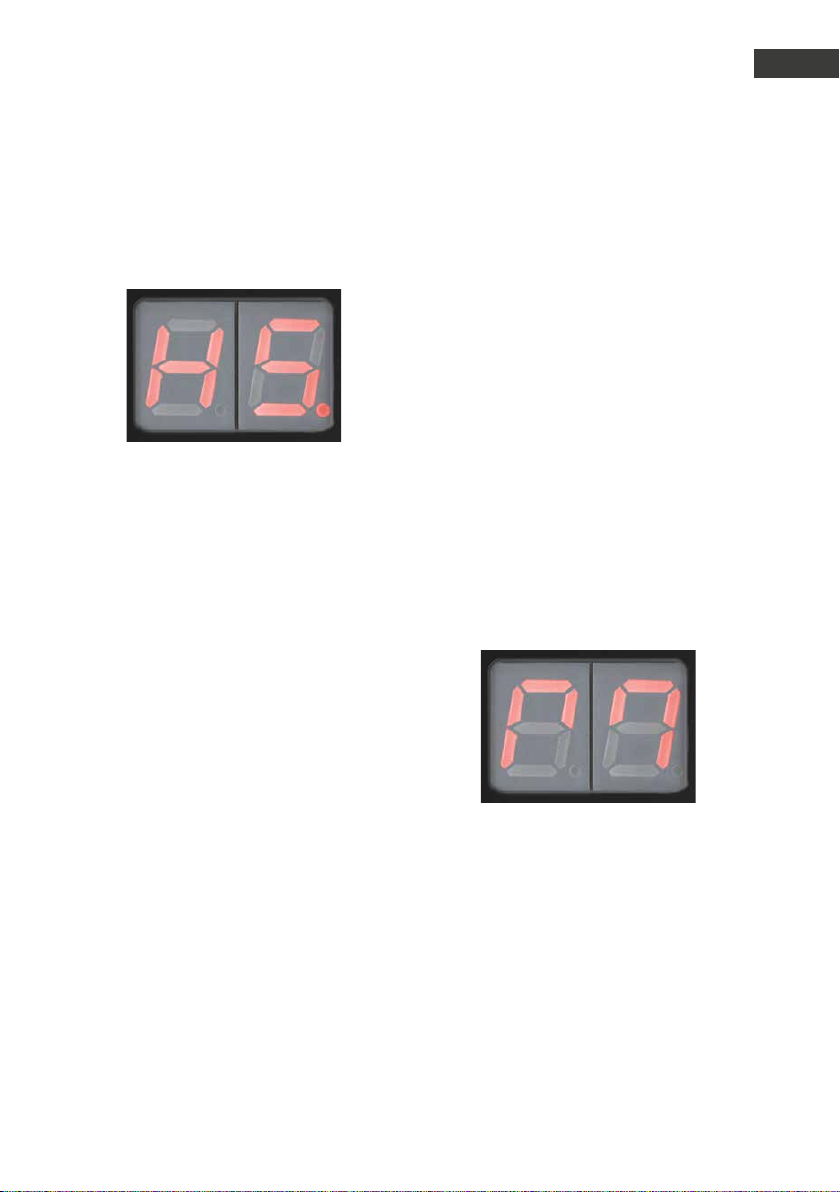
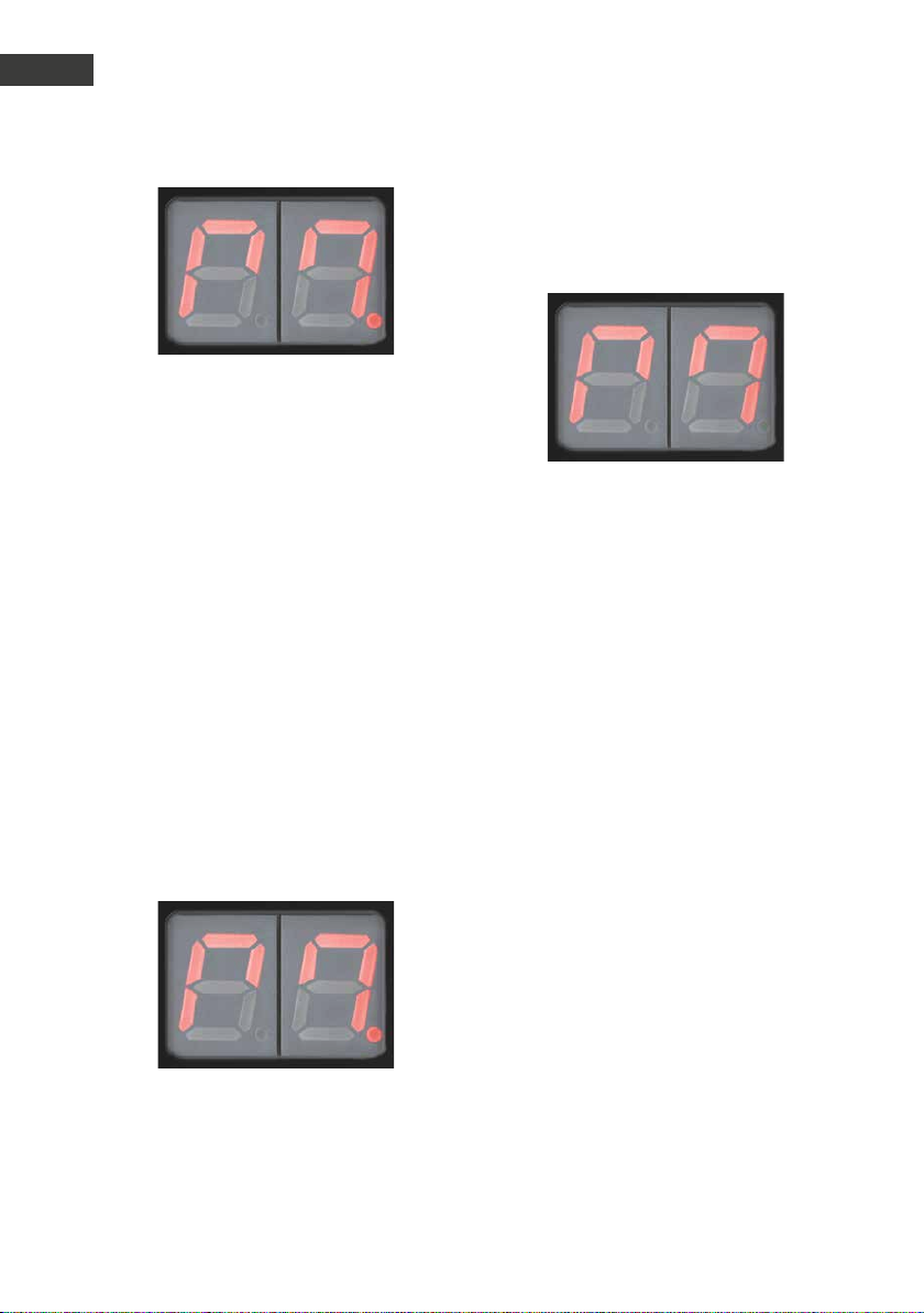
Halten Sie die Masterkarte vor den Karten-
leser. Die Speicherplätze werden bis 190
(„1.9“) durchgezählt. Danach erscheint
folgende Anzeige:
Anschließend erscheinen die Türöffnerzeiten
nacheinander.
H0 = 0,5 Sekunden
H1 = 1 Sekunde
...
H9 = 9 Sekunden
Entfernen Sie bei der gewünschten Zeit die
Masterkarte. Die Anzeige im Display leuch-
tet für ca. 3 Sekunden dauerhaft und blinkt
danach für ca. 6 Sekunden.
22 www.behnke-online.de
Anleitung myintercom Plus IP-Video Türstation
Kartenleser
D
Halten Sie die Masterkarte erneut vor den
Kartenleser, während die Anzeige blinkt. Die
angezeig te Zeit wird programmiert und der
rechte Dezimalpunkt leuchtet.
Die Masterkarte kann nun entfernt werden.
Die Anzeige erlischt.
4.4. Zweite Masterkarte
Zweite Masterkarte programmieren
Um ein Höchstmaß an Sicherheit zu gewährleisten, kann die Werksmasterkarte nur von
Telecom Behnke GmbH programmiert werden.
Deshalb sollte diese unbedingt an einem
sicheren Ort aufbewahrt werden.
Es besteht die Möglichkeit, neben der Werksmasterkarte einen weiteren Transponder als
2. Masterkar te zuzulassen. Hierzu wird die
mitgelieferte Werksmasterkarte benötigt.
Halten Sie die Werksmasterkarte vor den
Kartenleser. Die Speicherplätze werden bis
190 („1.9“) durchgezählt. Danach erscheint
folgende Anzeige:
Entfernen Sie die Werksmasterkar te von dem
Kartenleser. Die Anzeige leuchtet für ca. 3
Sekunden dauerhaft und blinkt danach für
ca. 6 Sekunden. Halten Sie den Transponder,
der als 2. Masterkarte dienen soll, vor den
Kartenleser.
Der neue Transponder ist nun als 2. Masterkarte programmier t und der rechte Dezimalpunkt leuchtet.
23www.behnke-online.de
Anleitung myintercom Plus IP-Video Türstation
D
Kartenleser
Die zweite Masterkar te kann nun entfernt
werden. Die Anzeige erlischt.
Hinweis: Ein bereits als Ausweis gespeicherter Transponder kann nicht als 2.Masterkarte
verwendet werden. In diesem Fall springt die
Anzeige zu dem entsprechenden Speicherplatz.
Zweite Masterkarte löschen
Das Löschen der Werksmasterkarte ist nicht
möglich. Für das Löschen der 2. Masterkar te
wird die „Werksmasterkar te“ benötig t.
Halten Sie die Werksmasterkarte vor den Kar-
tenleser. Die zweite Masterkarte wird gelöscht
und der rechte Dezimalpunkt erlischt.
Die Werksmasterkar te kann nun entfernt
werden. Die Anzeige erlischt.
Halten Sie die Werksmasterkarte vor den
Kartenleser. Die Speicherplätze werden bis
190 („1.9“) durchgezählt. Danach erscheint
folgende Anzeige:
Entfernen Sie die Werksmasterkar te von dem
Kartenleser. Die Anzeige leuchtet für ca. 3
Sekunden dauerhaft und blinkt danach für ca.
6 Sekunden.
24 www.behnke-online.de
Anleitung myintercom Plus IP-Video Türstation
Zusatzmodule
. KONFIGURATION
Die myintercom App wird laufend um neue Features und Funktionen erweitert, das neuste
Handbuch kann über die Webseite www.myintercom.de angefordert werden.
D
5.1. Starten der App „myintercom“
Laden Sie die App „myintercom“ je nach
Typ des Smartphones oder Tablet aus dem
Apple AppStore bzw. Google Play Store
herunter. Die in dieser Anleitung gezeig ten
Screenshots wurden auf einem iOS-Gerät
erstellt. Die Darstellung der App unter Android
identisch. Nach dem Start der App sehen Sie
einen leeren Star tbildschirm. Um die App mit
Ihrer myintercom Video-Türstation nutzen
zu können, fügen Sie zuerst einen Benutzer
zur Video-Türstation hinzu, wie es im Kapitel
„Administration der Video-Türstation“
beschrieben ist. Fügen Sie dann die VideoTürstation hinzu, wie es im Kapitel „Verwalten
von Video-Türstationen“ beschrieben ist. Dor t
benötigen Sie die Zugangsdaten, die Sie beim
Hinzufügen des Benutzers generiert haben.
Legen Sie in jedem Fall zuerst einen Benutzer
in der Video-Türstation an. Wenn die myintercom-Funktion auch außerhalb des eigenen
Netzwerkes über Internet erfolgen soll, so ist
die Aktivierung der entsprechenden Lizenz über
www.myintercom.de/activate erforderlich.
5.2. Übersicht
Nachfolgend sind die drei wichtigsten Bildschirme der App „myintercom“ dargestellt.
Hauptbildschirm
Danach ist die myintercom-Einrichtung abgeschlossen.
Dieser Bildschirm erscheint beim Starten der
App.
25www.behnke-online.de
Anleitung myintercom Plus IP-Video Türstation
D
Konfiguration
Historie
Auf dieser Seite können Sie die letzten Anrufe
von der Tür mit Uhrzeit und Bild einsehen. Die
Sprache wird nicht aufgezeichnet. Pro VideoTürstation wird eine Historie von 20 Besuchern
gepflegt.
Administration
Auf dieser Seite nehmen Sie die Einrichtung
der Video-Türstation und der App vor.
26 www.behnke-online.de

Anleitung myintercom Plus IP-Video Türstation
Konfiguration
D
5.3. Administration der Video-Türstation
Alle für das myintercom-System notwendigen
Einstellungen können mit Hilfe der App auf
dem Smartphone oder Tablet vorgenommen
werden. Ein separater PC ist nicht erforderlich. Die Administration der Video-Türstation
kann von einem beliebigen Endgerät aus
durchgeführt werden, unabhängig davon, ob
dieses Endgerät später benutzt wird, um mit
der Video-Türstation zu kommunizieren oder
nicht. Über den Punkt „Einstellungen“ aus
dem Hauptmenü der App erreichen Sie das
Einstellungs-Fenster:
Wählen Sie hier „ Administration “ aus, um
die Video-Türstation zu verwalten. Vorher
werden Benutzername und Passwort
abgefragt:
Diese Daten entnehmen Sie bitte dem Beiblatt
„Einrichtung“. Der Benutzername enthält
bereits den Bezug zur Video-Türstation, sodass
keine weiteren Informationen über die zu
konfigurierende Video-Türstation eingegeben
werden müssen. Drücken Sie „Weiter
sich an der Video-Türstation anzumelden.
“
, um
27www.behnke-online.de

Anleitung myintercom Plus IP-Video Türstation
D
Konfiguration
Administration
Im
Benutzer verwalten
Drücken Sie „Hinzufügen“, um einen neuen
Benutzer anzulegen oder auf einen Benut-
zernamen, um die Benutzereinstellungen zu
ändern.
Administrationsbereich können Sie
Benutzer hinzufügen
▸
Benutzer verwalten
▸
Entscheiden, ob das Licht der Video-Tür-
▸
station beim Rufaufbau automatisch akti vier t wird
Den NTP-Server einrichten
▸
im Anrufprotokoll immer die korrekte Uhr zeit angezei gt.)
28 www.behnke-online.de
(Somit wird

Anleitung myintercom Plus IP-Video Türstation
Konfiguration
D
Der Benutzername und das Passwort
werden automatisch ausgefüllt. Geben Sie
einen „Namen “ ein, um den Benutzer später
leichter identifizieren zu können. Ein „Speichern
möglich. Notieren Sie die hier angezeigten
Zugangsdaten („Benutzer“ und „Passwort“).
Sie werden später benötigt, wenn die App zum
Zugriff auf die Video-Türstation konfiguriert
wird. Dies ist im nächsten Kapitel „Hinzufügen
von Video-Türstationen“ beschrieben. Wählen
Sie mit Türklingel den Klingelknopf aus, der
dem Benutzer zugeordnet werden soll. Dieser
Benutzer erhält eine Push-Meldung, sobald der
zugeordnete Klingelknopf gedrückt wird. Jedem
Benutzer kann genau ein Klingelknopf zugeordnet werden. Somit wird jeder Klingelknopf wie
eine eigene myintercom-Anlage konfiguriert.
Will der Benutzer bei mehr als einem Klingelknopf benachrichtigt werden, so müssen mehrere Benutzer angelegt werden und auf dem
Endgerät des Nutzers mehrere Türstationen
eingerichtet werden (eine pro Klingelknopf).
Drücken Sie „Speichern“, um den Benutzer auf
der Video-Türstation hinzuzufügen.
„Löschen
Video-Türstation. Dieser gelöschte Benutzer
hat danach keinen Zugriff mehr auf die VideoTürstation. „Ändern
des Benutzers. Es wird ein neues zufälliges
Passwort generiert und in der Kamera gespeichert. Tragen Sie dieses neue Passwort danach
auf dem Smartphone oder Tablet des Benutzers
ein. Drücken Sie „Per Mail versenden “, um
die aktuell angezeigten Benutzerdaten per
E-Mail zu versenden.
“
ist ohne Eingabe eines Namens nicht
“
löscht den Benutzer von der
“
ändert das Passwort
Weisen Sie hier dem Benutzer eine Türklingel
zu:
29www.behnke-online.de

Anleitung myintercom Plus IP-Video Türstation
D
Konfiguration
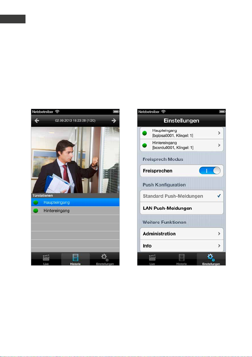
5.4. Verwalten von Video-Türstationen
Drücken Sie auf dem Startbildschirm auf „Einstellungen“, der Einstellungs-Bildschirm wird
angezeigt.
um erweiterte Informationen und Hilfestellung
zur installierten App zu erhalten. Mit dem
Schalter „Freisprechen “ können Sie den
Freisprechmodus aktivieren bzw. deaktivieren.
Die Schaltfläche „Lan Push-Meldungen “
aktiviert Pushmeldungen im Lan Netzwerk,
auch wenn keine Verbindung zum Internet
besteht.
Drücken Sie „Hinzufügen “, um eine neue
Video-Türstation auf diesem Endgerät hinzuzufügen oder drücken Sie auf eine bereits
konfigurierte Video-Türstation , um die Konfiguration zu ändern. Drücken Sie „Info “,
30 www.behnke-online.de

Anleitung myintercom Plus IP-Video Türstation
Konfiguration
D
Türstation hinzufügen
Bezug zur IP-Video Türstation wird auch hier
wieder über den Benutzernamen hergestellt.
Somit ist keine weitere Angabe der hinzuzufügenden IP-Video Türstation notwendig.
Schalten Sie Push-Meldungen aus, wenn Sie
nicht gestört werden möchten. Mittels Schieberegler
Video-Türstation eingestellt werden.
Drücken Sie „Klingelton “ und wählen Sie aus
der folgenden Liste einen Klingelton aus:
kann die Lautsprecher-Lautstärke der
Tragen Sie die Daten des unter „Administration “ (s. Seite 27) angelegten Benutzers
hier ein. Unter „Türstation
Beschreibung für den Eingang eingeben. Der
“
können Sie eine
Drücken Sie auf „Speichern
gang abzuschließen. „Löschen
diese Video-Türstation aus der Konfiguration der App. Mit dem Schalter „Internet “
können Sie prüfen, ob die Internet-Funktion
der Türstation freigeschaltet ist, siehe
www.myintercom.de/activate.
“
, um den Vor-
“
entfernt
31www.behnke-online.de

Anleitung myintercom Plus IP-Video Türstation
D
Konfiguration
Drücken Sie auf „Impressum “, um weitere
Informationen zum Hersteller der App zu
erhalten.
Drücken Sie „Feedback
Feedback-Formular aufzurufen. Nutzen Sie
bitte dieses Feedback Formular auch, wenn Sie
technische Unterstützung benötigen. Die Feedback-Mail enthält Informationen zur Version
der App und zum Typ des Smar tphones oder
Tablet sowie zu dessen Betriebssystem. Diese
Daten helfen unseren Technikern dabei, Fragen
schneller beantworten zu können. Die Daten
werden ausschließlich zu Support-Zwecken
verwendet und nicht an Dritte weitergegeben.
“
, um unser
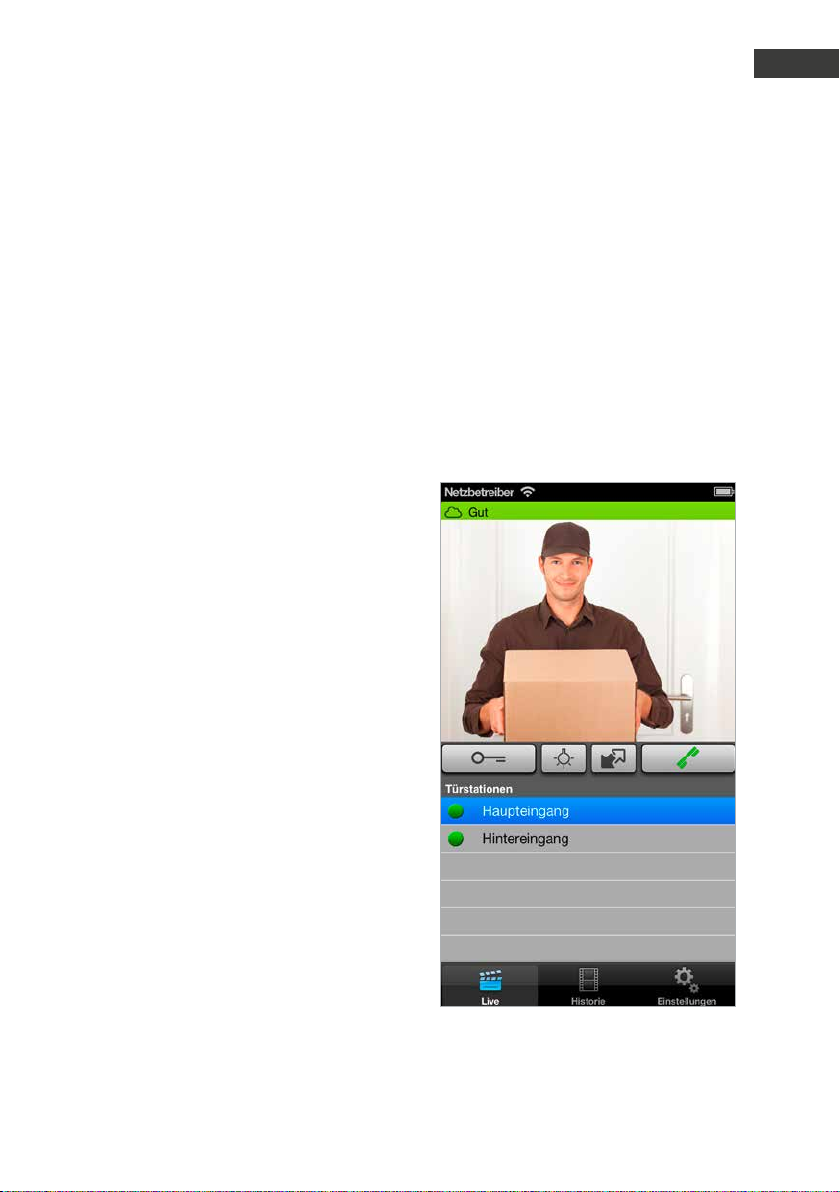
5.5. Bedienung der App
Die App gliedert sich in zwei Teile: Live-Video
und Historie. Der Benutzer kann jederzeit auf
das Live-Bild der Video-Türstation zugreifen.
Gespräche führen
Auf diesem Bildschirm sehen Sie das Video
von der Tür. Der Balken am oberen Bildrand
zeigt an, ob das Video über L AN oder Internet
empfangen wird. Die Farbe und Länge gibt
einen Anhaltspunkt für die Qualität der Über-
tragung (rot: schlecht, grün: gut).
In der unteren Liste sehen Sie die auf
diesem Smartphone konfigurierten IP-Video
32 www.behnke-online.de

Anleitung myintercom Plus IP-Video Türstation
Konfiguration
D
Türstationen. Der Punkt vor dem Namen
zeigt die Erreichbarkeit der Video-Türstation
an. Video-Türstationen mit rotem Punkt
sind offline, Video-Türstationen mit grünem
Punkt sind online. Durch Druck auf die Zeile
können Sie das Video von einer anderen
Video-Türstation aufrufen. Mit dem Knopf „Tür
öffnen
dem Knopf „Licht an
Beleuchtungs-Ring. Sie können mit dem Knopf
Drücken auf „Abheben “ aktivieren Sie
den Lautsprecher der Video-Türstation. Sie
können dann den oder die Besucher ansprechen.
“
lösen Sie den Türöffner aus, mit
das zweite Zusatz-Relais aktivieren. Durch
“
aktivieren Sie den
Historie
Mit Hilfe der Historien-Funktion können Sie
später nachvollziehen, wer während Ihrer
Abwesenheit geklingelt hat. In der oberen
Leiste wird der Zeitpunkt des Türrufes
angezeig t . Durch Wischen oder Drücken
der Pfeil-Knöpfe in der oberen Leiste
können Sie die bis zu 20 Einträge abrufen. In
der unteren Tabelle
welcher Video-Türstation Sie die Historie
sehen wollen. Der Punkt vor dem Namen der
Video-Türstation zeigt auch hier die Erreichbarkeit an.
wählen Sie aus, von
33www.behnke-online.de

Anleitung myintercom Plus IP-Video Türstation
D
Technische Merkmale
. TECHNISCHE MERKMALE
Standardmerkmale der IP-Video Türstation:
IP-Kamera
▸
Beleuchtungsring
▸
Lautsprecher
▸
Mikrofon
▸
Echounterdrückung
▸
Ausführungen mit 1–3 Ruf tasten möglich
▸
Beleuchtete Beschriftungsfelder
▸
(bis zu 3 Beschriftungsfelder möglich)
PoE fähig
▸
Sabotageschutz
▸
1 potentialfreies Türöffnerrelais belastbar
▸
mit 30 V DC /maximaler Strom 1 A
1 potentialfreies Zusatzrelais belastbar mit
▸
30 V DC /maximaler Strom 1 A
3 potentialfreie Türgongrelais belastbar mit
▸
30 V DC /maximaler Strom 1 A
1 Türöf fner (12 V DC /AC max. 9 W) kann
▸
direkt versorgt werden
Optik
¼“ CMOS-Sensor
▸
Brennweite 2,9 mm, F2.0
▸
Horizontaler Bildwinkel 84°
▸
Vertikaler Bildwinkel 48°
▸
Beleuchtung 1.2 – 100000 Lux, F2.0,
▸
0 Lux mit eingeschalteter LED
Verschlusszeit 1 /24500s bis 1 /6s
▸
Auflösung, Framerate und Qualität wird
▸
dynamisch an die Netzwerkverbindung
angepasst
Audio
Proprietäre Audio-Über tragung zur
▸
myintercom App
Integrierte Akustische Echo-Unterdrückung
▸
Voll-Duplex
▸
Verstärker-Leistung 1 Watt
▸
Netzwerk
IPv4, HTTP, HTTPS *, SSL/ TLS *, QoS Layer 3
▸
DiffSer v, Bonjour, UPnP, SNMPv1 /v2c /v3
(MIB-II), DNS, NTP, RTSP, RTP, TCP, UDP,
IGM P, RTCP, I CMP, DHCP, A RP, SOCKS.
* Dieses Produkt enthält Software, die vom
Open SSL Projekt im Open SSL Toolkit entwickelt wurde (www.openssl.org)
HTTPS-Verschlüsselung
▸
Zusatzmodule
Ausführungsvariante der myintercom Plus
▸
Video-Türstation mit Kartenleser (nur eine
Ruftaste möglich)
Ausführungsvariante der myintercom Plus
▸
Video-Türstation mit Zweidrahtempfänger
Optionales Sicherheitsrelais
▸
Video
Motion-JPEG, H.264 Kompression
▸
HDTV Bildsensor von Axis Communications
▸
Proprietäre Videoübertragung zur
▸
myintercom App
34 www.behnke-online.de
Anschluss
Versorgung durch PoE nach IEEE 802.af-2003
▸
bzw. durch Zweidrahttechnik
Leistungsaufnahme: ~5,8 W
▸

Wichtig! Bitte beachten Sie, dass es sich bei
der angegebenen Leistungsaufnahme lediglich um die Aufnahme der Türstation inklusive
der Zusatzmodule handelt. Achten Sie bei
Verwendung eines Netzgerätes darauf, dass
die maximale Leistungsabgabe nicht unter der
Leistungsaufnahme der Türstation zusätzlich
zum verwendeten Türöffner liegt, falls dieser
direkt über sie Türstation versorgt wird.
Anleitung myintercom Plus IP-Video Türstation
Technische Merkmale
D
35www.behnke-online.de

Anleitung myintercom Plus IP-Video Türstation
D
Fehlerbehebung
. FEHLERBEHEBUNG
Die Relais schalten nicht
Lokal
▸
Bitte überprüfen Sie, ob der Gehäusedeckel
angeschraubt ist, da sonst der Sabotagekontakt auslöst und aus Sicherheitsgründen die
Relais deaktiviert werden.
Zusätzlich bei Verwendung des Zusatz-
▸
moduls „Sicherheitsrelais“
Bitte überprüfen Sie die Verkabelung von der
Türstation zum Sicherheitsrelais hin (Siehe
Kapitel 3.1 Sicherheitsrelais). Drücken Sie
danach den Taster am Sicherheitsrelais für
mindestens 2 Sekunden.
Der Türöffner schaltet nicht
Gleiche Vorgehensweise wie bei „Relais schalten nicht“. Bitte überprüfen Sie zusätzlich den
Spannungsbetriebsbereich des Türöffners. Es
können nur Türöffner angeschlossen werden,
welche mit einer Spannung von 12V DC /AC
betrieben werden.
Der Türgong ertönt nicht
Bitte überprüfen Sie die Einstellung des
Gongschalters (siehe Kapitel 4.6 Türgong
einstellen).
Kein Zugriff auf die Türstation möglich
Bitte überprüfen Sie Ihre Installation und
vergewissern sich, dass der Aufbau zu der
jeweiligen Anschlussmöglichkeit passt
(Verwendung von PoE, Zweidrahttechnik).
Sehen Sie dazu in Kapitel 2 Installation nach.
Nehmen Sie den Gehäusedeckel ab und kont-
rollieren Sie bitte, ob die grüne Power-LED auf
der Rückseite des Gerätes leuchtet.
Sollte dies nicht den gewünschten Erfolg
bringt, tauschen Sie das verwendete Patch-
kabel.
Falls nach Überprüfung der Installation und
Vorgehensweise bei der Fehlerbehebung
immer noch ein Fehler vorhanden sein sollte,
wenden Sie sich bitte an unsere 24h Service-
Hotline Tel.: +49 (0) 68 41/ 81 77-777
36 www.behnke-online.de

. BEMASSUNG
12,5
100
Anleitung myintercom Plus IP-Video Türstation
Bemaßung
SeitenansichtFrontblende
504
D
12,5280
Benötigter
Wand-Hohlraum
Breite 101 mm
Höhe 271 mm
125
50 4
100
305
280
270
100
▸ Wir empfehlen eine Hohlraumtiefe von 60-70 mm
(inklusive Platz für die Verkabelung)
▸ Bohrungen mit Gewinde M4 =
M4
37www.behnke-online.de

Anleitung myintercom Plus IP-Video Türstation
D
Bemaßung
Unterputzgehäuse
118
56
15
280
100
Aufputzgehäuse
120
Ø 4
Ø 5,5
20
20
13
298
13
1
55
275
15
Ø 3
70
301
15
1
38 www.behnke-online.de

Anleitung myintercom Plus IP-Video Türstation
Rechtliche Hinweise
D
. RECHTLICHE HINWEISE
1. Änderungen an unseren Produkten, die dem
technischen For tschritt dienen, behalten wir
uns vor. Die abgebildeten Produkte können im
Zuge der ständigen Weiterentwicklung auch
optisch von den ausgeliefer ten Produkten
abweichen.
2. Abdrucke oder Übernahme von Texten,
Abbildungen und Fotos in beliebigen Medien
aus dieser Anleitung – auch auszugsweise –
sind nur mit unserer ausdrücklichen schriftlichen Genehmigung gestattet.
3. Die Gestaltung dieser Anleitung unterliegt
dem Urheberschutz. Für eventuelle Irrtümer,
sowie inhaltliche- bzw. Druckfehler (auch bei
technischen Daten oder innerhalb von Grafiken und technischen Skizzen) übernehmen
wir keine Haf tung.
Elektromagnetische
Verträglichkeit
Niederspannungsrichtlinie
Unsere Produkte sind selbstverständlich nach
den CE-Richtlinien zertifiziert, die EU-weit
gültig sind: EMV nach 2004/108/EG sowie
Niederspannungsrichtlinie nach 2006/95/EG
Infos zum Produkthaftungsgesetz:
1. Alle Produkte aus dieser Anleitung dürfen
nur für den angegebenen Zweck verwendet
werden. Wenn Zweifel bestehen, muss dies
mit einem kompetenten Fachmann oder unserer Serviceabteilung (siehe Hotline-Nummern)
abgeklärt werden.
2. Produkte, die spannungsversorgt sind (insbesondere 230 V-Netzspannung ), müssen vor
dem Öffnen oder Anschließen von Leitungen
von der Spannungsversorgung getrennt sein.
3. Schäden und Folgeschäden, die durch Eingriffe oder Änderungen an unseren Produkten
sowie unsachgemäßer Behandlung verursacht
werden, sind von der Haftung ausgeschlossen. Gleiches gilt für eine unsachgemäße
Lagerung oder Fremdeinwirkungen.
4. Beim Umgang mit 230 V-Netzspannung oder
mit am Netz oder mit Batterie betriebenen
Produkten, sind die einschlägigen Richtlinien
zu beachten, z. B. Richtlinien zur Einhaltung
der elektromagnetischen Verträglichkeit oder
Niederspannungsrichtlinie. Entsprechende
Arbeiten sollten nur von einem Fachmann
ausgeführt werden, der damit vertraut ist.
5. Unsere Produkte entsprechen sämtlichen,
in Deutschland und der EU geltenden, technischen Richtlinien und Telekommunikationsbestimmungen.
39www.behnke-online.de

Anleitung myintercom Plus IP-Video Türstation
D
Konformitätserklärung
40 www.behnke-online.de

Version 1.0
D myintercom Plus IP-Video Türstation Seite ...........3
GB myintercom Plus IP video door station Page ........... 43

myintercom Plus IP video door intercom Instructions
GB
Important information
Important information
Please note that Behnke call stations and
accessories may only be installed and serviced by qualified electricians in compliance
with the relevant safety provisions.
Please ensure that the devices are safely
CONTACT
Info hotline
For detailed information on our products,
projects and services:
+49 (0) 68 41/ 81 77-700
24 h service hotline
You need help? We are there for you
24 hours a day, to advise you in all
technical matters and to help you to
get started:
+49 (0) 68 41/ 81 77-777
disconnected from the power system (mains
adapter) and mains power supply before
carr ying out any maintenance or repair work.
Further legal notices are given on page 79.
Telecom Behnke GmbH
Gewerbepark „An der Autobahn“
Robert-Jungk-Straße 3
66459 Kirkel
Internet and email address
www.behnke-online.de
info@behnke-online.de
42 www.behnke-online.de

myintercom Plus IP video door intercom Instructions
Contents
CONTENTS
1. Introduction 44
1.1. What’s in the box ........................................................................................................... 44
1.2. General information ...................................................................................................... 44
1.3. The myintercom Plus IP video door station .................................................................... 46
1.4. Recommended mounting position ................................................................................. 47
1.5. Light conditions ............................................................................................................ 47
1.6. Changing the nameplates .............................................................................................47
1.7. Attaching the door station .............................................................................................48
1.8. Use scenarios ...............................................................................................................49
2. Installation 52
2.1. POE ............................................................................................................................... 54
2.2. Two-wire technology .................................................................................................... 54
2.3. Door opener/Relay/Gong .............................................................................................. 55
2.4. Setting the door gong................................................................................................... 56
3. Add-on modules 57
3.1. Security relay ................................................................................................................ 57
GB
4. Card reader 60
4.1. Selecting the memory location .......................................................................................61
4.2. Transponder ..................................................................................................................61
4.3. Configuring the door opener time ................................................................................. 62
4.4. Second master card ...................................................................................................... 63
5. Configuration 65
5.1. Starting the “myintercom” app...................................................................................... 65
5.2. Overview ...................................................................................................................... 65
5.3. Administration of the video door station ....................................................................... 67
5.4. Managing video door stations ...................................................................................... 70
5.5. Using the app ................................................................................................................ 72
6. Technical features 74
7. Troubleshooting 76
8. Dimensions 79
9. Legal Notices 79
43www.behnke-online.de

myintercom Plus IP video door intercom Instructions
GB
Introduction
. INTRODUCTION
1.1. What’s in the box
myintercom Plus IP video door station
▸
User instructions
▸
“Setup” leaflet
▸
For version with two-wire technology:
▸
• 2 coaxial adapters
• 2-wire receiver for installation in the
protected indoor area
1.2. General information
Features
The myintercom IP video door station is a
compact device with integrated camera,
loudspeaker and microphone. It has up to
three call buttons, which are equipped with
illuminated nameplates.
The integrated tamper contact, together with
a separately available, remote security relay,
fulfils increased security and convenience
requirements.
smartphone or tablet PC becomes the remote
terminal for the myintercom IP video door
station. With the smartphone or tablet PC, the
user can see who is at the door, can speak to
them and if necessar y can open the door from
their smar tphone or tablet PC by pressing a
button. To this end the smartphone or tablet
PC is logged into the local WLAN.
In order to be able to accept the call from the
door when you are out, away from home or
the office, the video door station must be
activated via www.myintercom.de/activate.
The image and tone (sound) transmission then
takes place via the internet (WLAN / 3G / LTE).
In poor light conditions the lighting in the
video door station can be activated during the
call from a smartphone or tablet PC.
Thanks to the integrated echo suppression
(acoustic echo canceller), a full duplex voice
connection exists between the smartphone or
tablet PC and the door. The last 20 events are
saved in the door station with a camera image
and the time so that no call from the door is
missed.
The myintercom technolog y also enables the
existing infrastructure to be used for video
door communication. With myintercom, the
44 www.behnke-online.de

myintercom Plus IP video door intercom Instructions
Introduction
GB
System requirements
The following minimum requirements are necessar y for use of the myintercom IP video
door station:
Two-wire technology variant: Two-wire
▸
telecommunication cable
Ethernet variant: PoE (to IEEE 802.af-2003)
▸
fed Cat5 ethernet cable
Unused network por t at the switch/router
▸
WLAN
▸
The myintercom app from the Apple
▸
AppStore or Google PlayStore
DHCP Server, which issues an IP address,
▸
subnet mask, gateway and DNS server
(Standard)
Optionally, if access to the door station is
▸
also required outside of the LAN, e.g. away
from home via the internet: Landline
network broadband internet connection
(without proxy/socks ser ver) via an internet
provider, e.g. DSL 2000 or faster. Flatrate
(data volume) recommended. The door
intercom must be able to set up a direct
connection with the internet (without proxy/
socks server).
iOS 5 and higher – iPhone4S, iPhone5, iPad
▸
with activated Apple ID for downloading the
free app
Android 4 and higher – smartphones and
▸
tablet PCs (at least Dual Core Processor 2 x
1.2 GHz or faster) and activated Google Play
account for downloading the free app
Attention: Please keep the “Setup“ leaflet
in a safe place. It is not possible to change
the configuration at a later date without the
access data printed on it.
45www.behnke-online.de

myintercom Plus IP video door intercom Instructions
GB
Introduction
1.3. The myintercom Plus IP video door station
5
5
Camera
Lighting ring
Loudspeaker
Call button
Nameplate
Microphone
Screw cover
Card reader
Card reader display
46 www.behnke-online.de

myintercom Plus IP video door intercom Instructions
Introduction
GB
1.4. Recommended mounting position
The recommended installation height for an
optimum camera viewing angle is 155 cm.
For further details, please refer to the Figure.
1.5. Light conditions
External lighting is recommended for
improved image quality in poor light conditions or at night.
1.6. Changing the nameplates
1
To change the nameplates, remove the housing cover
of the door station f irst.
Then push the paper st rips into the op ening provided
in the nameplate .
155 cm
50 cm
Then s crew the housing cover back on ag ain –
finished.
47www.behnke-online.de

myintercom Plus IP video door intercom Instructions
GB
Introduction
1.7. Attaching the door station
Attach the housing and connect the door stationPrepare the on-wall housing for cable ent ry
Inser t the door station in the housing and use four
screws to screw it onto the on- wall housing.
Then screw on t he screw covers - finished!
The example shows the installation of the
on-wall variant. The door station can alternatively also be installed as a concealed
“in-wall” installation. In this case the suitable
in-wall housing is installed in the wall opening
or in the cavity cutout and the door station is
fixed in place as shown.
48 www.behnke-online.de

1.8. Use scenarios
Local
The diagram shows use inside a residential or
office building with access via the local WLAN.
myintercom Plus IP video door intercom Instructions
Introduction
GB
Additional relay
(garage)
Office storey
Foyer
DSL router /
switch
WLAN
WLAN
Tablet PC / Smar tphone
myintercom Plus Video door
station with camera
Ethernet
Door
opener
49www.behnke-online.de

myintercom Plus IP video door intercom Instructions
GB
Introduction
Global
The diagram shows use outside a residential
or off ice building with access via the internet.
INTERNET
Office storey
WLAN, 3G/4G
(UMTS/LTE)
Voice
Image
Foyer
myintercom Plus Video door
station with camera
DSL router /
switch
Additional
relay (barrier)
Ethernet
Door
opener
50 ww w.behnke-online.de

Local or global (with security relay)
The diagram shows use inside a residential or
office building with internal security relay.
myintercom Plus IP video door intercom Instructions
Introduction
GB
Office storey
Foyer
DSL router /
switch
Additional
relay (garage)
Security relay:
Safety and security through installation in
▸
the tamper-proof indoor area
Connected with myintercom Plus IP video
▸
door station
Security
relay
Tablet PC / Smar tphone
WLAN
myintercom Plus Video door
WLAN
Secure communication
Communication between the security relay
▸
station with camera
Ethernet
Door
opener
and door station over secured protocol
Provides two floating relay contacts
▸
51www.behnke-online.de

myintercom Plus IP video door intercom Instructions
GB
Installation
. INSTALLATION
The door station’s electronics
Ethernet socket
The LAN connection is usually made via
an RJ-45 connector . Alternatively, the
individual wires can also be connected via a
terminal strip : The network is connected
to the terminals marked with 1 (orange-white),
2 (orange), 3 (green-white) and 6 (green) to
EIA / TIA 568 B. The number denotes the pin
number of the RJ45 connector/the RJ45 box.
Alternative ethernet connection
Simultaneous connection of socket and screw
terminals is not allowed! This can cause a
defect in the door station!
Door opener connection
Connection option for one door opener (12
V max. 9 W). See Chapter 2.4 Door opener/
Relay/Gong.
Relay 1 (door opener relay)
Isolated connection (rating: 30 VDC /max. 1
A) for one door opener, which is activated by
the “myintercom” app. See Chapter 2.4 Door
opener/Relay/Gong.
Relay 2 (additional relay)
Isolated connection (rating: 30 VDC /max.
1 A), which can be activated by the “myin-
tercom” app. See Chapter 2.4 Door opener /
Relay/Gong.
52 www.behnke-online.de

Gong connections
Isolated connections for three door gongs
(rating 30VDC /max. 1A), which are activated
at the press of a button. See Chapter 2.4 Door
opener/Relay/Gong.
Gong switch
The gong switch can be used to set the
number of gong strokes when the button is
pressed. See Chapter 2.5 Setting the door
gong.
Anti-tamper contact
See Chapter 1.2 General information.
Supply socket of the security relay
See Chapter 3.1 security relay.
myintercom Plus IP video door intercom Instructions
Installation
Electronics of the door station with two-wire
technology
GB
Connection socket for security relay
See Chapter 3.1 security relay.
Connection for door opener button
See Chapter 2.4 Door opener/Relay/Gong.
Connection socket for coaxial cable
Data transmission and supply option for the
myintercom Plus video door station. See
Chapter 2-wire technology on page 54.
Attention: Simultaneous use of a 2-wire transmitter and the ethernet is not allowed.
53www.behnke-online.de

myintercom Plus IP video door intercom Instructions
GB
Installation
The myintercom Plus IP video door station
provides several options for supplying the
door station and the add-on modules with
power.
2.1. POE
This option can be used as soon as a
PoE-compatible router or switch or a PoE
injector (to IEEE 802.3af-2003) is available.
To connect the door station, please remove
the housing cover and plug the patch cable
into the RJ45 socket provided.
2.2. Two-wire technology
Another option for supplying the door station
with power is to use the add-on 2-wire trans-
mitter module. Remove the cover of the door
station housing and connect a coaxial cable to
the socket provided on the two-wire trans-
mitter. If you do not have a coaxial cable, but
only two wires, please used the coaxial cable
adapter supplied.
Important! The housing cover must be
screwed back on again in order for the tamper
protection to work!
54 www.behnke-online.de
Important! The housing cover must be
screwed back on again in order for the tamper
protection to work!
The second end of the coaxial cable is
connected to the two-wire receiver. Feed PoE
via the cable, which is plugged into the RJ45
socket of the two-wire receiver. To do this,
please use a PoE injector or a PoE-compatible
router or switch to IEEE 802.at standard.

myintercom Plus IP video door intercom Instructions
Installation
GB
2.3. Door opener/Relay/Gong
Remove the cover of the door station housing
and connect the components as follows:
DO
The door opener, which the door station
operates directly (12 V DC / AC max. 9 W), is
connected to the terminal marked “door”.
Relay 1 is available at the terminal marked
“R1” and relay 2 is available at the terminal
marked “R2”.
Optional externa l door
opener button (provided
by the cu stomer)
DO
External door opener power adapter
(see Technical Featur es)
Relay 1 connection
Note: The door opener voltage and relay 1
are always connected in parallel.
External power adapter
(see Technical Featur es)
Lighting control,
Garage door opener,
Barr ier control, ...
Optional externa l door
opener button (provided
by the cu stomer)
If the door opener is supplied directly via the
door station, an external door opener button
can be connected to open the door.
Relay 2 connection
55www.behnke-online.de

myintercom Plus IP video door intercom Instructions
GB
Installation
The door gongs are connected to the terminals
marked “Gong”. Button 1 switches gong 1,
button 2 switches gong 2, … The but tons are
numbered from the top down.
Gong 1
(provided
by the
customer)
Bell transformer
(pro vided by the
customer)
Important! The housing cover must be
screwed back on again in order for the tamper
protection to work!
2.4. Setting the door gong
You can set the number of gong strokes
triggered each time the button at the door
station is pressed. In the basic setting the
station switches the gong on and off twice
when the button is pressed (switch position
2). The number can be set between zero and
nine with the help of a rotary switch on the
door station’s electronics. In switch position
zero the gong does not sound, instead a push
message appears at the terminal device.
To set the rotary switch, please remove the
housing cover and set the switch to the
required number.
Important! The housing cover must be
screwed back on again in order for the tamper
protection to work!
56 www.behnke-online.de

. ADDON MODULES
3.1. Security relay
myintercom Plus IP video door intercom Instructions
Add-on modules
This module provides fur ther security measures by moving the door opener and the two
relays into the protected interior of the house
or building.
The security relay is connected to the door
station by four wires and is also supplied with
power through these.
Connect the following door station terminals
with the terminals of the securit y relay:
GB
Markings on the
door station
SR- SRSR+ SR+
TXD TXD
RXD RXD
– NO (make contact), rating 30 VDC
max. 1 A
Floating contact, separate power supply
required for the connected device.
Markings on the
security relay
57www.behnke-online.de

myintercom Plus IP video door intercom Instructions
GB
Add-on modules
The door station is reset with the help of the
Reset button , if the anti-tamper contact
has tripped. To do this, ensure that the housing cover of the IP door station is screwed on
and press the button on the securit y relay
Equally, with this add-on module it is also
possible to use a second, additional relay.
This can be used, for example, to control a
garage door opener, a second door opener, a
barrier or the outdoor lighting.
for at least 2 seconds.
A door opener (12 V DC/AC max. 9 W) can be
connected directly to the terminals of the
security relay marked “door opener”. Optionally, it can also be operated with an external
power supply at relay 1. Please note that the
door opener voltage and relay 1 are always
switched simultaneously.
58 www.behnke-online.de

myintercom Plus IP video door intercom Instructions
Add-on modules
GB
DO
DO
External door opener power
adapter (see tec hnical features)
Optional ext. Door
opener button (provided
by the cu stomer)
External power adapter
(see Technical Featur es)
Optional ext. Confirmation button
(pro vided by the cu stomer)
Lighting control,
Garage door opener,
second door opener,
Barr ier control, ...
Relay 1 and door opener Relay 2
Important! Please note that the myintercom Plus IP video door station can only operate one
door opener directly. This may only be connected to the security relay or only to the door station.
Note: The security relay does not provide a separately controllable relay, it replaces relay 1 and
2, and the door opener voltage of the door station.
59www.behnke-online.de

myintercom Plus IP video door intercom Instructions
GB
Card reader
. CARD READER
It is possible to purchase the myintercom Plus
IP video door station with an integrated card
reader. In this way, simple access control can
be realised by issuing all authorised persons
with an RFID card which is registered at the
door station. Relay 1 and the door opener are
switched when a registered card is held in
front of the card reader.
Display overview
Display of the 10s digits of the current
memory location (10; 20; 30; ... 90; 1.1;
1.2; 1.3; ... 9.9)
Display of the unit digits of the current
memory location (from 0 to 9 )
This decimal point symbolises the 100s
digit. From memory location 100 the left hand decimal point lights up (e.g. “5.3”
for 153). The decimal point does not light
up for memory locations 0 to 99.
(e.g. “5 3” for 53)
This decimal power indicates whether the
current memory location is allocated.
(E.g. “3.8.”: the memory location 138 is
being used by a transponder).
If the display flashes, changes can be made.
Other operating displays:
The transponder within the sensing range has
not been programmed yet.
Malfunction!
The card reader is not working properly, an
internal error or fault exists. Please send in
the door station for repair.
60 www.behnke-online.de

myintercom Plus IP video door intercom Instructions
Card reader
GB
4.1. Selecting the memory location
Hold the master card in front of the card
reader. The display switches itself on:
The memory locations are displayed from 0 to
10 in steps of 1. (00...01...02...03...)
From the 10th memory location the counting
continues in steps of 10s (fast mode).
To count in steps of 1 again, remove the
master card briefly and then hold it in front
of the card reader again. The next 10 memory
locations are now counted in single steps
again, then fast mode starts again.
To select a memory location, remove the
master card. The display lights up continuously for approx. 3 seconds and then flashes
for approx. 6 seconds. The memory location
can now be programmed or deleted.
4.2. Transponder
Programming the transponder
Attention:
When programming the transponder, ensure
that an already allocated memory location is
not over written with a new number, because
the transponder whose number is overwritten
loses its authorisation as a result.
Hold the master card in front of the card
reader and select the required memor y location (see “4.1. Selecting the memory location“
on page 61). Hold the new transponder
in front of the card reader, while the display
flashes. The transponder is programmed with
the selected memory location and the righthand decimal point lights up.
Note: If an already saved transponder is held
in front of the card reader, the display jumps
to its memory location.
You can now remove the transponder. The display jumps automatically to the next memory
location. To end the write operation, remove
the master card, the display goes out and the
card reader switches to operating mode.
61ww w.behnke-online.de

myintercom Plus IP video door intercom Instructions
GB
Card reader
Deleting the transponder
Hold the master card in front of the card
reader and select the required memor y location (see “4.1. Selecting the memory location“
on page 61).
The memory location is allocated if the righthand decimal point lights up.
Now remove the master card from the card
reader. The memory location lights up continuously for approx. 3 seconds and then flashes
for approx. 6 seconds. Hold the transponder
in front of the card reader again, while the
display flashes.
The memory location is now deleted and the
right-hand decimal point is no longer lit.
4.3. Configuring the door opener time
The user can set the door opener time at
between 0.5 seconds to 9 seconds. A hold
time of 4 seconds is set in the factory.
Hold the master card in front of the card
reader. The memory locations are counted off
up to 190 (“1.9 ”). The following display then
appears:
The door opener times then appear one af ter
the other.
H0 = 0.5 seconds
H1 = 1 second
...
H9 = 9 seconds
Remove the master card at the required time.
The display lights up continuously for approx.
3 seconds and then flashes for approx. 6
seconds.
62 www.behnke-online.de

myintercom Plus IP video door intercom Instructions
Card reader
GB
Hold the master card in front of the card
reader again, while the display flashes. The
displayed time is programmed and the righthand decimal point is lit.
The master card can now be removed. The
display goes out.
4.4. Second master card
Programming a second master card
To ensure maximum security, the factory
master card can only be programmed by
Telecom Behnke GmbH. Therefore, it should
always be kept in a secure place.
In addition to the factory master card, it is
possible to approve another transponder as a
2nd master card. To do this, you will need the
factory master card supplied.
Hold the factor y master card in front of
the card reader. The memory locations are
counted of f up to 190 (“1.9 ”). The following
display then appears:
Remove the factory master card from the card
reader. The display lights up continuously
for approx. 3 seconds and then f lashes for
approx. 6 seconds. Hold the transponder,
which is to be used as the 2nd master card, in
front of the card reader.
The new transponder is now programmed as
the 2nd master card and the right-hand decimal point lights up.
63www.behnke-online.de

myintercom Plus IP video door intercom Instructions
GB
Card reader
The second master card can now be removed.
The display goes out.
Note: A transponder that has already been
saved as an ID pass cannot be used as the
2nd master card. In this case the display
jumps to the corresponding memory location.
Deleting the second master card
It is not possible to delete the factory master
card. To delete the 2nd master card you will
need the “factory master card”.
Hold the factor y master card in front of
the card reader. The second master card is
deleted and the right-hand decimal point is no
longer lit.
The factor y master card can now be removed.
The display goes out.
Hold the factor y master card in front of
the card reader. The memory locations are
counted of f up to 190 (“1.9 ”). The following
display then appears:
Remove the factory master card from the card
reader. The display lights up continuously
for approx. 3 seconds and then f lashes for
approx. 6 seconds.
64 www.behnke-online.de

myintercom Plus IP video door intercom Instructions
Configuration
. CONFIGURATION
New features and functions are added continuously to the myintercom app, the latest manual
can be requested from the website www.myintercom.de/en.
GB
5.1. Starting the “myintercom” app
Download the “myintercom” app from the
Apple AppStore or Google Play Store, depending on the type of smartphone or tablet PC.
The screenshots shown in these instructions
were created on an iOS device. The app display under Android is identical. After starting
the app you can see an empty Start screen. In
order to be able to use the app with your myintercom video door station, you must first add
a user to the video door station, as described
in the “Video Door Station Administration”
chapter. Then add the video door station, as
described in the “Managing video door stations” chapter. There you will need the access
data that you generated on adding the user.
Always create a user in the video door station
first. If the myintercom function is also to be
accessed outside your own network via the
internet, it is necessary to activate the relevant
licence via www.myintercom.de/activate.
The myintercom setup is then completed.
5.2. Overview
The three most important screens of the
“myintercom” app are shown in the following.
Main screen
This screen appears when you star t the app.
65www.behnke-online.de

myintercom Plus IP video door intercom Instructions
GB
Configuration
History
On this page you can view the most recent
calls from the door with the time and image.
The speech / voice data is not recorded. A
history of 20 visitors is maintained for each
video door station.
Administration
On this page you set up the video door
intercom and the app.
66 www.behnke-online.de

myintercom Plus IP video door intercom Instructions
Configuration
GB
5.3. Administration of the video door
station
All settings necessary for the myintercom
system can be made with the help of the app
on a smartphone or tablet PC. A separate PC is
not required. The video door station administration can be carried out from any terminal
device, regardless of whether this terminal
device is used later to display the camera
image or not. Use the “Settings” item from
the main menu of the app to open the Set tings
window:
Select “Administration ” to manage the
video door station. You are asked for your user
name and password f irst:
Please refer to the “Setup” leaflet for this
information. The user name already contains
the reference to the video door station, so
that no further information has to be entered
about the video door station to be configured.
Press “Next ”, to log on to the video door
station.
67www.behnke-online.de

myintercom Plus IP video door intercom Instructions
GB
Configuration
Administration
Manage users
Press “Add” to create a new user, or a user
name to change the user settings.
The user name and the password are
filled automatically. Enter a “Name
”, so that
In the administration area you can
Add users
▸
Manage users
▸
Decide whether the light of the video door
▸
station is activated automatically on setting
up a call
Set up the NTP server (so that the correct
▸
time is always displayed in the call log.)
68 www.behnke-online.de

myintercom Plus IP video door intercom Instructions
Configuration
GB
the user can be more easily identified later.
It
is not possible to “Save ” without entering a name. Make a note of the access data
displayed here (“User” and “Password”). It will
be needed later when the app for accessing
the video door station is configured. This is
described in the next chapter “Adding video
door stations”. Press Doorbell to select the
doorbell button, which is to be assigned to
the user. This user receives a push message
as soon as the assigned doorbell button is
pressed. Each user can be assigned one doorbell button. In this way, each doorbell button is
configured as if it were a separate myintercom
system. If the user wants to be notified for more
than one doorbell button, several users have
to be created and several door stations have to
be set up on the user’s terminal device (one per
doorbell button). Press “Save” to add the user
to the video door station. “Delete ” deletes
the user from the video door station. This
deleted user then no longer has any access to
the video door station. “Change ” changes
the user’s password. A new random password
is generated and saved in the camera. Then
enter this new password on the smartphone or
tablet PC of the user. Press “Send by email ”,
to send the currently displayed user details by
email.
Here you assign a doorbell to the user:
69www.behnke-online.de

myintercom Plus IP video door intercom Instructions
GB
Configuration
5.4. Managing video door station
On the Start screen press “Settings”; the Settings screen is displayed.
switch to enable or disable hands-free mode.
The “LAN Push Messages ” button enables
push messages in the LAN network, even if
there is no connection with the internet.
Press “Add ”, to add a new video door station
to this terminal device or press an already
configured video door station , to change
the configuration. Press “Info ”, to obtain
more detailed information and help with the
installed app. You can use the “Hands-free ”
70 www.behnke-online.de

myintercom Plus IP video door intercom Instructions
Configuration
GB
Adding a door station
erence to the IP video door station is made via
the user name. Therefore, it is not necessary to
enter any further information about the IP video
door station to be added. Switch off Push Messages , if you do not want to be disturbed.
You can use the slide controller to set the
loudspeaker volume of the video door station.
Press “Ring tone ” and choose a ring tone
from the following list:
Enter the details of the user created under
“Administration ” here (see page 67).
Under “Door station ” you can enter a
description for the entrance. Here too the ref-
Press “Save ”, to end the process. “Delete
”
removes this video door station from the
app’s configuration. You can use the “Internet
”
switch to check whether the internet function of the door station is activated, see
www.myintercom.de/activate.
71www.behnke-online.de

myintercom Plus IP video door intercom Instructions
GB
Configuration
Press “Imprint ”, for more information on
the maker of the app.
Press “Feedback ”, to open our feedback
form. Please use this feedback form too, if you
need technical support. The feedback email
contains information on the app version and
the type of smar tphone or tablet PC and its
operating system. This information helps our
technicians to answer questions more quickly.
The data is used for suppor t purposes only and
is not passed on to third parties.
5.5. Using the app
The app is divided into two parts: Live Video
and History. The user can access the live image
of the video door station at any time.
Making calls
On this screen you can see the video from the
door. The bar at the top edge of the screen
indicates whether the video is being received
via LAN or internet. The colour and length of
the bar gives an indication of the transmission
quality (red: poor, green: good).
In the bottom list you can see IP video
door station configured on this smartphone.
72 www.behnke-online.de

myintercom Plus IP video door intercom Instructions
Configuration
GB
The dot in front of the name indicates the
availability of the video door station. Video
door station with a red dot are offline, video
door stations with a green dot are online. If
you press the row you can open the video from
another video door station. Press the “Open
door ” button to trigger the door opener;
press the “Light on ” button to activate
the lighting ring. You can activate the second
additional relay by pressing the button.
Press “Pick up ” to activate the loudspeaker
of the video door station. You can then talk to
the visitor.
History
With the help of the History function you can
later see who rang the doorbell during your
absence. The time of the door call is displayed
in the top bar . You can open up to 20
entries by swiping or pressing the arrow
buttons in the top bar. In the bottom table
you can choose the video door station for
which you would like to see the histor y. The
dot in front of the name of the video door
station also shows its availability.
73www.behnke-online.de

myintercom Plus IP video door intercom Instructions
GB
Technical features
. TECHNICAL FEATURES
Standard features of the IP video door
intercom:
IP camera
▸
Lighting ring
▸
Loudspeaker
▸
Microphone
▸
Acoustic echo canceller (AEC)
▸
Models with 1–3 call buttons possible
▸
Illuminated nameplates
▸
(up to 3 nameplates possible)
PoE compatible
▸
Tamper protection
▸
1 floating door opener relay, load rating
▸
30 V DC/maximum current 1 A
1 floating additional relay, load rating
▸
30 V DC/maximum current 1 A
3 floating door gong relays, load rating
▸
30 V DC/maximum current 1 A
1 door opener (12 V DC/AC max. 9 W) can be
▸
supplied directly
Optics
¼” CMOS sensor
▸
Focal length 2.9 mm, F2.0
▸
Horizontal picture angle 84°
▸
Vertical picture angle 48°
▸
Lighting 1.2 – 100000 Lux, F2.0,
▸
0 Lux with LED switched on
Shutter speed 1/24500s to 1/6s
▸
Video
Motion-JPEG, H.264 compression
▸
Axis Communications HDTV image sensor
▸
Proprietary video transmission to the
▸
myintercom app
Resolution, frame rate and quality are
▸
adjusted dynamically to the network
connection
Audio
Proprietary audio transmission to the
▸
myintercom app
Integrated acoustic echo suppression (AEC)
▸
Full-duplex
▸
Amplifier output 1 wat t
▸
Network
IPv4, HTTP, HTTPS*, SSL/TLS*, QoS Layer 3
▸
DiffSer v, Bonjour, UPnP, SNMPv1/v2c/v3
(MIB-II), DNS, NTP, RTSP, RTP, TCP, UDP,
IGM P, RTCP, I CMP, DHCP, A RP, SOCKS.
* This product contains sof tware, which has
been developed by the Open SSL project in
the Open SSL Toolkit (w ww.openssl.org)
HTTPS encryption
▸
Add-on modules
Model variant of the myintercom Plus video
▸
door station with card reader (only one call
button possible)
Model variant of the myintercom Plus video
▸
door station with two-wire receiver
Optional security relay
▸
Connection
Supply through PoE to IEEE 802.af-2003 or
▸
through two-wire technology
Power input: ~5.8 W
▸
74 www.behnke-online.de

Important! Please note that the given power
input is only the input of the door station
including the add-on modules. If using a
power adapter, ensure that the maximum
power output is not less that the power input
of the door station plus the door opener used,
if this is supplied directly via the door station.
myintercom Plus IP video door intercom Instructions
Technical features
GB
75www.behnke-online.de

myintercom Plus IP video door intercom Instructions
GB
Troubleshooting
. TROUBLESHOOTING
The relays do not switch
Local
▸
Please check whether the housing cover
is screwed on properly, as otherwise the
anti-tamper contact trips and the relays are
deactivated for security reasons.
Additionally, if using the “Security relay”
▸
add-on module
Please check the wiring from the door station
to the security relay (see Chapter 3.1 Security
relay). Then press the button at the security
relay for at least 2 seconds.
The door opener does not switch
Repeat the same procedure as for “Relays do
not switch”. Please also check the voltage
operating range of the door opener. Only door
openers operated with 12V DC/AC voltage can
be connected.
The door gong does not sound
Please check the setting of the gong switch
(see Chapter 4.6 Setting the door gong ).
No access to the door station
Please check your installation and ensure that
the layout matches the respective connection
option (use of PoE, two-wire technology).
Refer to Chapter 2 Installation. Remove the
housing cover and check whether the green
Power-LED at the back of the device is lit.
If this does not solve the problem, please
replace the patch cable used.
If, after checking the installation and complet-
ing the troubleshooting procedure, an error or
fault still remains, please contact our 24h ser-
vice hotline on Tel.: +49 (0) 68 41/81 77-777
76 www.behnke-online.de

. DIMENSIONS
12,5
100
myintercom Plus IP video door intercom Instructions
Dimensions
Side viewFront panel
504
GB
12,5280
cavity required
Height 271 mm
125
Size of wall
Width 101 mm
50 4
100
305
280
270
100
▸ We recommend a cavity depth of 60-70 mm
(including space for the wiring)
▸ Drillholes with thread M4 =
M4
77www.behnke-online.de

myintercom Plus IP video door intercom Instructions
GB
Dimensions
In-wall housing
118
56
15
280
100
On-wall housing
120
Ø 4
Ø 5,5
20
20
13
298
13
1
55
275
15
Ø 3
70
301
15
1
78 www.behnke-online.de

myintercom Plus IP video door intercom Instructions
Legal Notices
GB
. LEGAL NOTICES
1. We reser ve the right to make changes to
our products, without notice, in the interest
of technical progress. As a result of continuous development, the products illustrated
can also differ visually from the delivered
products.
2. Reprint or copying of texts, figures and
photos from these instructions in any media –
even as extracts – are only required with our
explicit written approval.
3. The design and layout of these instructions
are copyright protected. We do not accept any
liability whatsoever for possible errors, as
well as content or printing errors (including in
technical data or within diagrams and technical sketches).
Electromagnetic Compatibility
Low Voltage Directive
Our products are naturally certified according
to the CE Directives, which apply EU-wide:
EMC Directive 2004/108/EC and Low Voltage
Directive 2006/95/EC
Info on the product liability law:
1. All products mentioned in these instructions may only be used for the stated purpose.
If any doubts exist, they must be clarif ied with
a competent, qualif ied person or our service
department (see hotline numbers).
2. Products with a voltage supply (especially
230 V mains voltage), must be disconnected
from the power supply before being opened or
connecting cables.
3. Damage and consequential damage,
caused by interventions or changes to our
products as well as improper handling are
excluded from the liabilit y. The same applies
to improper storage or external influences.
4. When handling 230 V mains voltage or
products operated with a mains power
supply or batter y, the relevant directives and
guidelines must be noted and followed, e.g.
directives concerning compliance with electromagnetic compatibility or the Low Voltage
Directive. Corresponding work should only
be carried out by a qualified person who is
familiar with these.
5. Our products conform to all technical
guidelines, directives and telecommunication
regulations applicable in Germany and the EU.
79www.behnke-online.de

myintercom Plus IP video door intercom Instructions
GB
Dimensions
80 www.behnke-online.de

myintercom Plus IP video door intercom Instructions
Notes
GB
81www.behnke-online.de

myintercom Plus IP video door intercom Instructions
GB
Notes
82 www.behnke-online.de

myintercom Plus IP video door intercom Instructions
Notes
GB
83www.behnke-online.de

Version 1.0
Kirkel, Februar 2014
TCB 1536_0713 500
Telecom Behnke GmbH
Gewerbepark „An der Autobahn“
Robert-Jungk-Straße 3
66459 Kirkel
Germany
Info-Hotline: +49 (0) 68 41/ 81 77-700
Service-Hotline: +49 (0) 68 41/ 81 77-777
Telefax: +49 (0) 68 41/ 81 77-750
info@behnke-online.de
www.behnke-online.de
 Loading...