

Page 1
Door Telephones
Emergency Telephones
Lift Emergency Communication Systems
Quick Reference Guide
Connection, Configuration, Mounting, Operation
Page 2
2
IMPORTANT NOTES ON COMMISSIONING
Thank you very much for buying a quality product from the
Behnke company. Your hands-free telephone has special
features, which you should take into account when
installing and configuring the unit:
(A) The hands-free telephone can be used on an
analogue PBX extension
or on an analogue direct
exchange line.
(B) The hands-free telephone can be used without any
additional power supply.
(C) The hands-free telephone works in full-duplex
mode (and can be switched to semi-duplex and
simplex).
Observing the following 9 notes, you will achieve the
greatest possible operating safety and speech quality with
your Behnke hand-free telephone.
1. MOUNTING CONDITIONS
• The optimum mounting height is when, during opera-
tion of the unit, there is a horizontal distance of 30–50
cm between the user and the loudspeaker and microphone.
• Always choose the greatest possible distance between
microphone and loudspeaker. Thus you will obtain the
highest possible intelligibility in full-duplex mode. (See
also Behnke volume classes in the product catalogue.)
• In the case of rear-mounting modules (i.e. modules
mounted behind an existing front wall or, for instance, a
car operating panel), make sure that there are large
enough sound inlet holes in front of the microphone
and sound outlet holes in front of the loudspeaker (at
least 50% of the loudspeaker membrane surface for
sound exit and 50% of the sound inlet of the microphone casing).
• To ensure best sound quality, always mount rear-mounting modules flush (without a distance) behind their
front wall. The supplied gasket must be mounted
between front wall and module.
2. OUTDOOR MOUNTING
• Only use Series 10 hands-free telephones in moisture-
protected situations.
• Hands-free telephones must be protected from direct
rain exposure.
• When Series 20 hands-free telephones are used at
weather sides, they should be equipped with a rain
guard in the case of flush mounting or with a surfacemounted casing in the case of surface mounting.
• In the case of flush mounting, always seal the upper
edge of the telephones well to protect them from rainwater (especially when the wall is not level, using e.g.
silicone), but at the lower edge leave a space in the centre unsealed to allow the water to run out.
3. GASKETS
Take care to ensure correct seat when mounting the supplied gaskets. In the case of Series 10 telephones this is
important for good sound quality and moisture protection
of the unit. In the case of Series 20 telephones this is
important for moisture protection. The gasket must be
seated snugly on the frame of the flush- or surface-mounted casing.
4.
DISTANCE OF ELECTRONICS FROM BUTTONS, LOUDSPEAKER AND MICROPHONE
• For basic electronics packages 20-0005, 20-0006 and
20-0018: 25 m max.
• For basic electronics package 20-0007 (also for
20-0057): buttons 100 m max., dial pad 25 m max.
• For BNOS lift emergency telephones 20-0018, 20-0021,
20-0022 and 20-0028: 25 m max.
• The loudspeaker and microphone each require the same
distance as the buttons.
5. CABLING
• Use Behnke patch cables or shielded cables such as IYST-Y or AY-ST-Y for mounting. Connect the cable shield
to the –12-V terminal of the special-purpose hands-free
telephone or lift emergency telephone (not to earth!).
• Extension of buttons with unshielded cables may result
in malfunctions of the basic electronics package.
6. ORIGINAL BEHNKE PARTS
Only use original Behnke parts as accessories or spare
parts – this also applies to plug-in power supplies! Only
this will ensure a trouble-free operation.
7. CONFIGURATION
The hands-free telephones may be configured locally on
the basic electronics package, remotely by telephone
(DTMF) or through a Behnke control station.
Alle hands-free telephones come with a factory standard
configuration.
8. REGULATIONS
Please observe the relevant regulations for the installation of telecommunications and electrical equipment.
9. DETAILED INFORMATION
Detailed information on the installation, configuration
and functions of our hands-free telephones can be found
in our comprehensive technical manuals
, which are
available as PDF downloads on the Internet:
www.behnke-online.com
We strongly recommend you read this information as
well – it will help you install your telephone in the best
possible manner and enable you to use all functions!
Page 3

3
CONTENTS
Important Notes on Commissioning.............................................. 2
Quick Reference Guide for Series 10 ........................................ 4 –8
Quick Reference Guide for Series 20
Including Local External Electronics ......................................... 4–8
Quick Reference Guide for Universal Units............................. 9– 13
Quick Reference Guide for BNOS
Lift Emergency Telephones ................................................... 14 –19
Fault Table................................................................................... 20
Extended Operation .................................................................... 21
Specifications.............................................................................. 22
Legal Information........................................................................ 23
Appendix.................................................................................... I–V
ENGLISH
Page 4
4
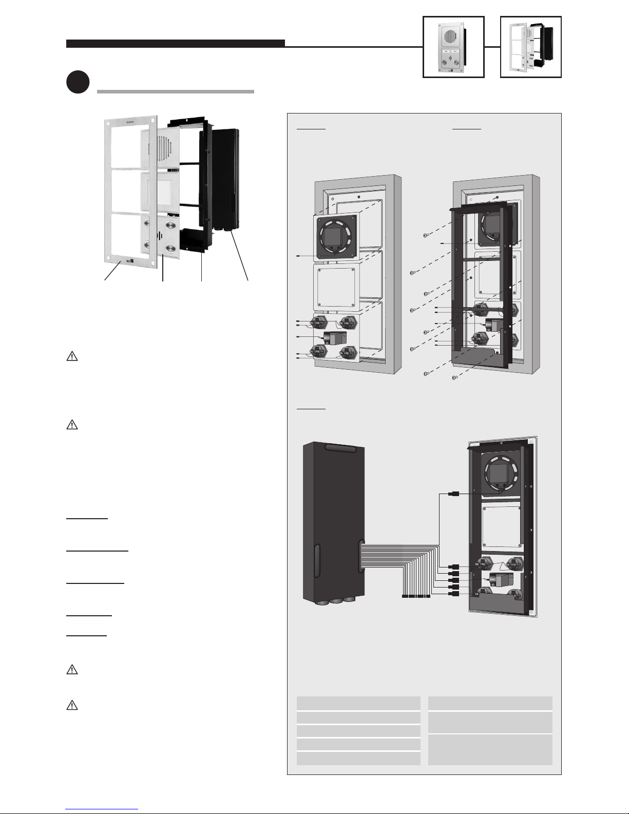
Mounting Notes:
When mounting the modules, special attention
must be payed to the aluminium brush-polish-
ing direction – important not only for optical
reasons but also, for example, for the drainage
of water from inside the telephone!
In the case of local external mounting of the
electronics, the module casing is replaced by an
open counterplate for the corresponding front
frame.
Connect the cables in the following order:
1. Buttons
. . . . . . . to the MQS plugs from 1 to 8
marked with a YELLOW ring
2. L
oudspeaker . . . to the plug marked with a
BLUE ring
3. Micr
ophone . . . . to the plug marked with a
WHITE ring
4. Dial pad
. . . . . . 12-pin white jack
5. Camer
a. . . . . . . . 4-pin black jack
Never confuse loudspeaker and microphone
plugs!
Unused cables should be laid with their open
end (plug) pointing downwards inside the
module casing (thus preventing moisture from
entering into the plug). Then place the electronics casing onto the module casing.
1
Assembly (only Series 20!)
Front frame
(with water drainage
slot at the bottom!)
Modules Electronics
casing
Module
casing
Step 1:
Insert modules into the frame
(leave them in the cardboard
surround).
S
tep 3:
Connect cables (see text on the left).
S
tep 2:
Screw module casing
to the frame.
L [B LU E ] = loudspeaker
M [W H IT E ] = microphone
1 to 8 [Y E LLO W ] = buttons 1 to 8
6-pin plug = video
12-pin plug = dial pad
Electronics casing
(with rubber caps at the
cable-entry holes)
Module casing
+ [R E D] = illumination
Z [Y ELLO W ] = addition
(option)
12-pin plug = dial pad
illumination
Pin assignment of
connecting cable:
Pin assignment of
illumination cable:
SERIES 10 / SERIES 20
Page 5
5
2
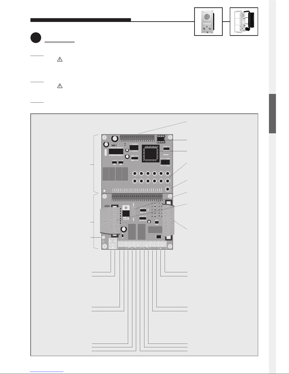
Connection
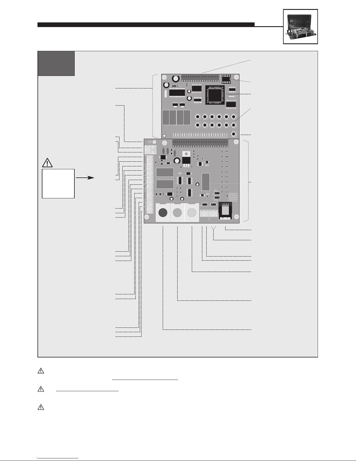
Step 1: Connect door opener to relay 1, if required.
Relay = voltage-free contact = only operates the door opener, without supplying it with electric energy;
the door opener requires its own power supply! Relay 2 is available for further switching functions (see
comprehensive technical manual; avalailable as PDF on the Internet).
S
tep 2: Connect 12 V DC, if required (potential-free – use Behnke plug-in power supply 20-9500).
Only required for: illumination, camera, integrated heating, integrated add-on amplifier;
not required for: telephone operation, including all functions.
S
tep 3: Connect telephone line (a/b line from analogue PBX extension or analogue direct exchange line) => a long
beep signals the telephone’s operational readiness.
12345
∗
67890#
∗
T
E
L
#
Telefonbau Behnke GmbH
TEL
a / b
– 12 V +
REL. 1 REL. 2
+ ALARM – VIDEO
Connector for electronics
extensions
EEPROM
Master processor
Internal configuration
and dialling keyboard
Heating resistor
Connecting cable for
illumination
Connecting cable for
modules
Video output
Alarm input
Relay 2
Additional
power supply
Telephone line
Earth
only wired in connection with
a module with camera
Alarm condition is active while
voltage is applied
Relay contact rating:
60 VA 24 W max.
0.5 A 120 V AC or 1 A 24 V DC
6 to 24 V DC
Relay 1
Relay contact rating:
60 VA 24 W max.
0.5 A 120 V AC or 1 A 24 V DC
12 V DC
potential-free voltage,
e.g. from Behnke plug-in
power supply
analogue direct
extension line or
PBX extension
Main board
Connection board
a wire
b wire
–
+
NC
Com.
NO
Video signal
Video earth
–
+
NO
Com.
NC
(only needed for modules with
illumination)
Telephone ‘ON’
featuring a voice-announcement
facility, a clock or a display
SERIES 10 / SERIES 20
ENGLISH
Page 6
6
SERIES 10 / SERIES 20
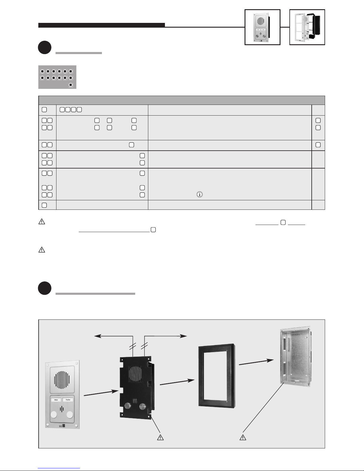
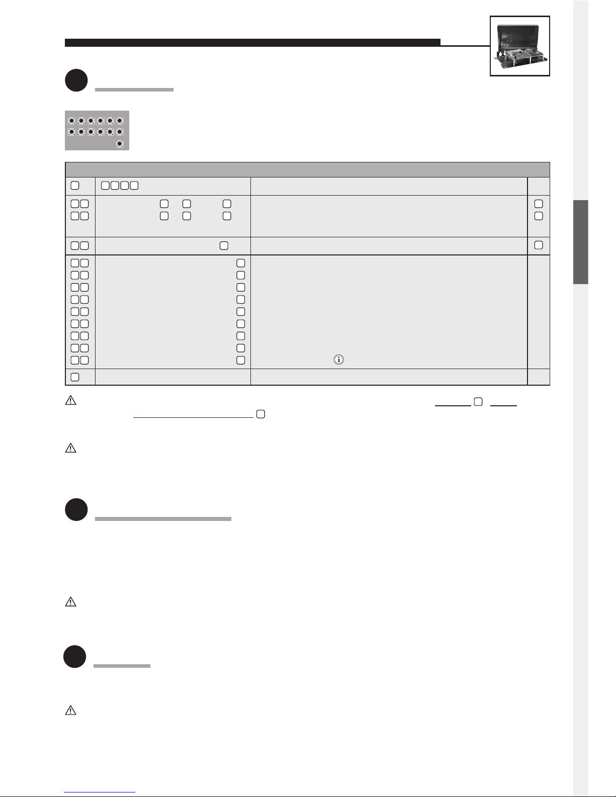
Use internal configuration keyboard (after removing the cover from the electronics casing).
Alternatively, configuration can also be done by DTMF telephone (touch-tone telephone).
Configuration is only possible with the a/b line (telephone line) connected.
Following the entry of each phone number and other configuration steps, do not forget to pr
ess the button!
In each case, finish configuration mode with . Otherwise it is possible that your entry is not stored correctly!
4.1 Series 10 / Home Office:
(factory setting) Enable configuration mode
A button from to , then Volume; 0 = low, 9 = high (full-duplex mode)
A button from to , then Volume; 0 = low, 9 = high (with add-on amplifier)
Note: Preferably use values between 1 and 4.
Number (4-digits max.), then Door-opener code (= 1st code for controlling relay 1)
Phone number to be dialled, then Phone number for 1 button —
Phone number to be dialled, then Phone number for 2 button —
Phone number to be dialled, then Phone number for 3 button (only Series 20) —
:: :
Phone number to be dialled, then Phone number for 8 button (only Series 20) —
Phone number to be dialled, then Phone number for button on the dial pad (only Series 20) —
End configuration mode
3
Configuration
4
Mounting / Installation
12345
∗
67890#
∗
T
E
L
#
#
0 6 0 59
#
#
#
#
#
#
#
#
0 0
0
9
0 7
1 0
2 1
2 2
2 8
2 9
2 3
n
n
n
0 0 0 0
For further configuration steps (relay control, sound settings, voice-announcement/real-time clock extension electronics), please refer to our comprehensive technical manual (available as PDF on the Internet – see also note on page 2).
Telephone a/b
Flush-mounted
casing 10-5200
(accessory)
To door opener
Faceplate
Electronics
package
Insert gasket!
Surface-mounted
frame 10-5100
(accessory)
Insert gasket!
Standard settingEntry (code / parameter) Function
Page 7
7
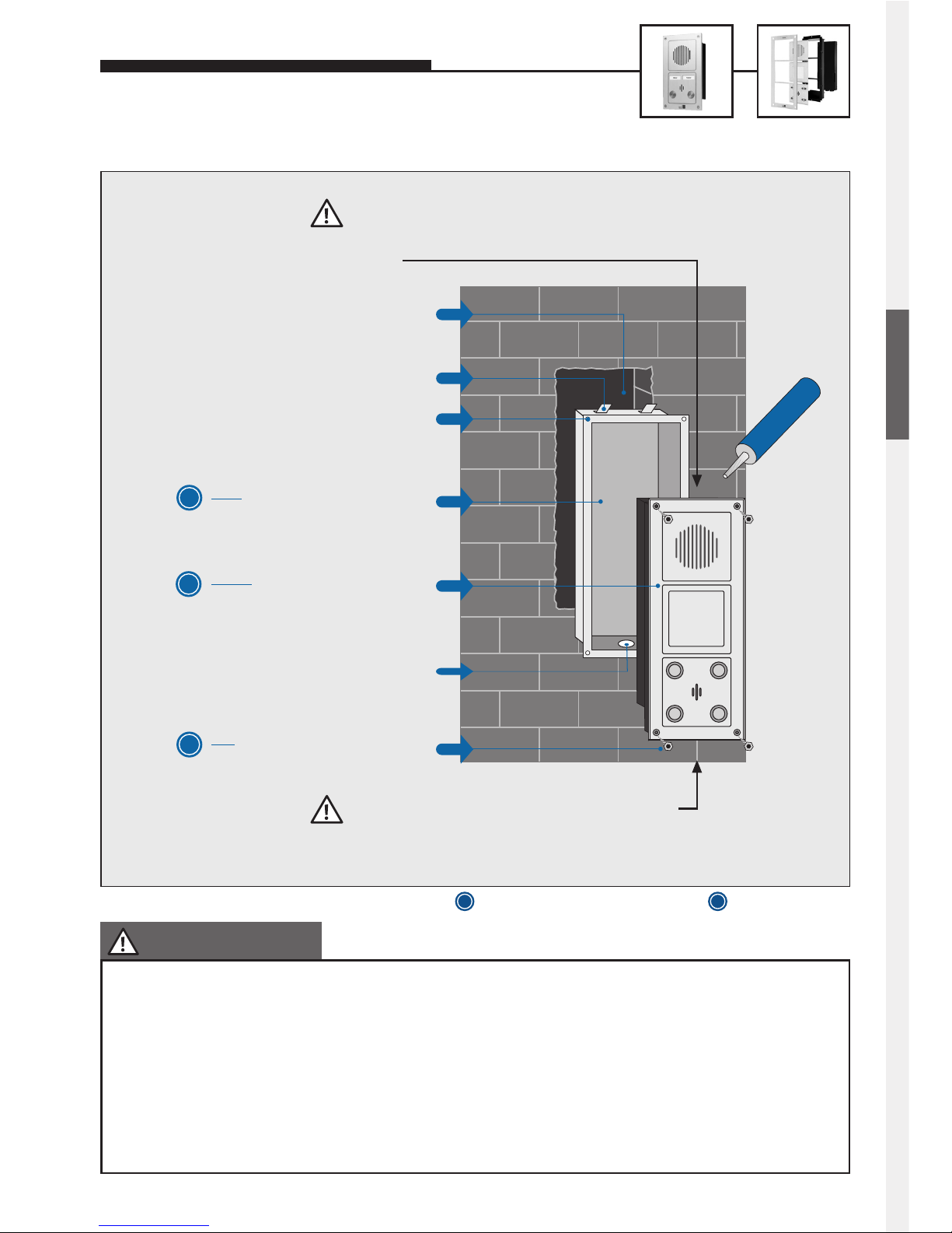
TO ENSURE TROUBLE-FREE
OPERATION, PLEASE NOTE:
Cut-out in the wall for flush-mounted casing
(if necessary, use cover trim)
Flush-mounted casing,
to be plastered in
M4 cage nuts (4 pcs.)
M4 Allen screws (4 pcs.)
incl. Allen key
Cable feed from below centre
Retaining tabs (4 pcs.)
S
O
Hands-free telephone
S
Leave water drainage slot in the central lower
part of the faceplate unsealed (do not close
completely with silicone or similar sealant).
Always make sure that no water can enter from above.
Seal with silicone. If necesarry, mount rain hood or rain
guard.
SILICONE
SERIES 10 / SERIES 20
4.2 Series 20 / Industrial Standard:
1. The gasket of the front frame must be seated snugly on the flush-mounted casing, since only this ensures the
proper sealing of the unit (applies also to surface-mounted casings).
2. The Series 20 telephones have a special water drainage slot in the central lower part on the back of the front
frame (in case water gets into the telephone despite the sealing) – that is why the lower edge must not be closed
completely with silicone but must be left unsealed in the centre!
3. Further notes on surface mounting, mounting with a rain guard, mounting with a rain hood and mounting inside a
cavity wall can be found in our comprehensive technical manual (available as PDF on the Internet; see also note
on page 2).
S
O
= Equipment supplied with the telephone
= Optional equipment
ENGLISH
Page 8
8
SERIES 10 / SERIES 20
5
Operation
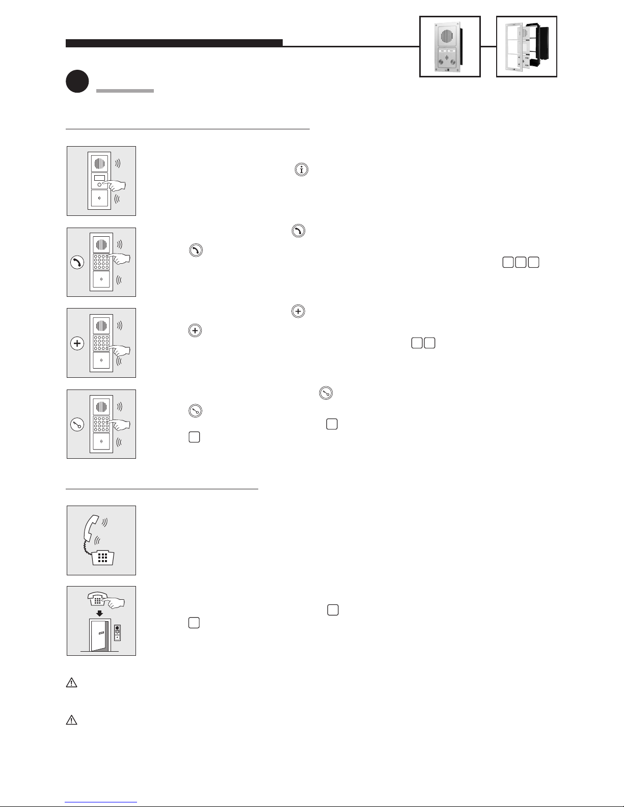
5.1 Functions on the hands-free telephone (= on the outside)
To call by means of call button:
• Press one of the call buttons (or button of the dial pad – only Series 20).
• The phone number programmed for the button (see step 3) will be dialled.
• When the call is accepted, a speech connection will be established (standard setting = full
duplex); the connection will be terminated automatically.
To call by means of dial pad with dial button (only Series 20):
• Press – you will hear a ringing tone.
• Dial phone number with the dial pad, e.g. an internal PBX extension number such as .
• When the call is accepted, a speech connection will be established (standard setting = full
duplex); the connection will be terminated automatically.
To call by means of dial pad with speed-dial button (only Series 20):
• Press – you will hear a ringing tone.
• Dial 2-digit speed-dial number (00 to 99) via the dial pad, e.g. .
• When the call is accepted, a speech connection will established (standard setting = full duplex);
the connection will be terminated automatically.
To open door by means of dial pad with code-lock button (only Series 20):
• Press – you will hear a ringing tone.
• Enter code number – standard setting =
• Press – the door opener will be triggered (via the telephone’s relay contact).
5.2 F
unctions on the telephone (= on the inside)
Call acceptance – speech connection when call comes in from the door:
• Depending on the PBX and telephone used, your display may show the number of the door
telephone or a text information such as ‘Door telephone’.
• Accept call coming from the door like a normal telephone call.
• Terminate speech connection by hanging up.
To open door from inside
• Enter code number – standard setting =
• Press – the door opener will be triggered.
Set system telephones from Siemens, Alcatel, Tenovis or other manufacturers to ‘DTMF suffix dialling’
(required for door-opener function and others).
Other possibilities of operation – e.g. how to change the hand-free telephone’s volume from inside during a connection
– can be found on page 21 and in our comprehensive technical manual (available as PDF on the Internet – see also
note on page 2).
1 2 7
3 1
0
0
#
#
Page 9
9
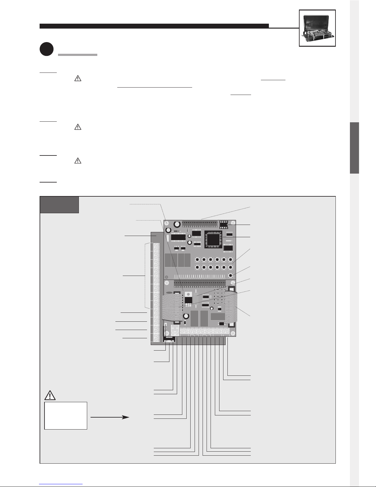
T8 T7 T6 T5 T4 T3 T2 T1 + MIC – + 12V – + ALARM– LS
12345
∗
67890#
∗
T
E
L
#
Telefonbau Behnke GmbH
TEL
a / b
– 12V +
REL. 1 REL. 2
+ ALARM – VIDEO
Anschluss für Elektronik-
erweiterungen
EEPROM
Masterprozessor
interne Konfigurations-
und Wähltastatur
Heizwiderstand
Verbindung
Anschlussplatine –
Subplatine
Anschlusskabel für
Module
Videoausgang
Alarmeingang
Relais 2
Zusatzversorgung
Telefonleitung
nur beschaltet in
Verbindung mit einem
Modul mit Kamera
Alarmzustand ist aktiv, solange
Spannung angelegt ist
Relaisschaltleistung:
max. 60 VA 24 W
0,5 A 120 V~ oder 1 A 24 V=
6 bis 24 V=
Relais 1
Relaisschaltleistung:
max. 60 VA 24 W
0,5 A 120 V~ oder 1 A 24 V=
12 V=
potentialfreie Spannung, z. B.
von Behnke-Steckernetzteil
analoger Hauptanschluss oder
Nebenstelle einer Telefonanlage
a-Ader
b-Ader
–
+
Ruhekontakt
Steuerkontakt
Arbeitskontakt
Videosignal
Video-Masse
–
+
Arbeitskontakt
Steuerkontakt
Ruhekontakt
Telefon „EIN“
Sprachansage, Uhr und Display
Hauptplatine
Anschlussplatine
Subplatine
Klemmen
Taste 1 bis 8
Mikrofon
nicht belegt
nicht belegt
Lautsprecher
RJ45-Buchse für
Tastwahlblock
Erde
T8 T7 T6 T5 T4 T3 T2 T1 + MIC – + 12V– + ALARM – LS
12345
∗
67890#
∗
T
E
L
#
Telefonbau Behnke GmbH
TEL
a / b
– 12V +
REL. 1 REL. 2
+ ALARM – VIDEO
Connector for electronics
extensions
EEPROM
Master processor
Internal configuration
and dialling keyboard
Heating resistor
Connectionboard/subboard
connecting cable
Connecting cable for
modules
Video output
Alarm input
Relay 2
Additional power supply
Telephone line
only wired in connection with
a module with camera
Alarm condition is active while
voltage is applied
Relay contact rating:
60 VA 24 W max.
0.5 A 120 V AC or 1 A 24 V DC
6 to 24 V DC
Relay 1
Relay contact rating:
60 VA 24 W max.
0.5 A 120 V AC or 1 A 24 V DC
12 V DC
potential-free voltage, e.g. from
Behnke plug-in power supply
analogue direct extension line
or PBX extension
a wire
b wire
–
+
NC
Com.
NO
Video signal
Video earth
–
+
NO
Com.
NC
Telephone ‘ON’
featuring a voice-announcement
facility, a clock or a display
Main board
Connection board
Subboard
Terminals for
buttons 1 to 8
Microphone
unused
unused
Loudspeaker
RJ45 jack for
dial pad
Earth
UNIVERSAL UNITS 20-0005/20-0006/20-0018
1
Connection
20-0005
Step 1: Connect loudspeaker, microphone and buttons.
Distance of the loudspeaker, microphone and buttons from the basic unit: 25 m max
.
Buttons must not hav
e a common return wire. To connect the basic electronics package with the user-
interface elements (loudspeaker, microphone and buttons) a shielded
cable must be used. IY-ST-Y or
AY-ST-Y. Connect shield to –12 V terminal (see also page 2). Mount dial pad at a distance of 25 m max.
(use Behnke patch cable for connecting the dial pad).
S
tep 2: Connect door opener to relay 1, if required.
Relay = voltage-free contact = only operates the door opener, without supplying it with electric energy;
the door opener requires its own power supply! Relay 2 is available for further switching functions
(see comprehensive technical manual; avalailable as PDF on the Internet).
S
tep 3: Connect 12 V DC, if required (potential-free – use Behnke plug-in power supply 20-9500).
Only required for: illumination, camera, integrated heating, integrated add-on amplifier;
not required for: telephone operation, including all functions.
S
tep 4: Connect telephone line (a/b line from analogue PBX extension or analogue direct exchange line) => a long
beep signals the telephone’s operational readiness.
Connect shield for
microphone and
buttons to –12 V,
not to earth!
ENGLISH
Page 10
10
12345
∗
67890#
∗
T
E
L
#
Telefonbau Behnke GmbH
. 2
+ ALARM −
T1 T2
– 12V +
REL. 1
REL.
TEL
a / b
T1
T2
− MIC +
LS
− MIC +
LS
1
4
7
*
2
5
8
0
3
6
9 i
#
+
\
\
+MLM C +MLM B
MLM A
red blue yellow
Telephone line
analogue direct
extension line or
PBX extension
a wire
b wire
Relay 2
Relay contact rating:
60 VA 24 W max.
0.5 A 120 V AC or 1 A 24 V DC
NC
Com.
NO
Relay 1
Relay contact rating:
60 VA 24 W max.
0.5 A 120 V AC or 1 A 24 V DC
NC
Com.
NO
Alarm input
Alarm condition is
active while voltage is
applied
6 to 24 V DC
–
+
EEPROM
Master processor
Internal
configuration and
dialling keyboard
Earth
Main board
Connection board
Dial pad
Loudspeaker
Microphone
MLM A
(main MLM)
MLM B
(additional MLM)
MLM C
(additional MLM)
Program phone
number with
configuration step 22
Program phone
number with
configuration step 23
Program phone
number with
configuration step 24
Telephone ’ON’
Buttons
Make or break
contacts may be used
as nonlocking buttons
Call button 1
Common contact
Call button 2
+
–
Additional
power supply
12 V DC
potential-free voltage,
e.g. from Behnke plug-in
power supply
–
+
Connector for electronics
extensions
featuring a voice-announcement
facility, a clock or a display
20-0006
20-0018
Connect shield
for microphone
and buttons to
–12 V, not to
earth!
UNIVERSAL UNITS 20-0005/20-0006/20-0018
In order to connect MLM A to C (microphone/loudspeaker modules = user units comprising loudspeaker, microphone
and button), you should use original Behnke patch cables
.
The integr
ated add-on amplifier (1 W) can only be activated for MLM A. The corresponding configuration steps can be
found in our comprehensive technical manual (available as PDF on the Internet – see also note on page 2).
Connection of multiple MLMs reduces the maximum distance between MLM and basic electronics package:
1 MLM = 25 m / 2 MLMs = 12.5 m each / 3 MLMs = 10 m each
Page 11
11
Standard settingEntry (code / parameter) Function
UNIVERSAL UNITS 20-0005/20-0006/20-0018
2
Configuration
Use internal configuration keyboard (open universal casing for this purpose).
Alternatively, configuration can also be done by DTMF telephone (touch-tone telephone).
Configuration is only possible with the a/b line (telephone line) connected.
• Mount the universal electronics package in a weather-proof location and connect it to the user unit(s).
• Observe the notes on cabling on pages 9 and 10 (25 m max., shielded cables, etc.).
• The connected buttons must meet the requirements of EN 60950 for telecommunications network voltages (TNV) circuits.
Normal bell push buttons do not usually meet these requirements; if required, use Behnke button 20-9100.
Further mounting information (with sample sketches) can be found in our comprehensive technical manual
(available as PDF on the Internet – see also note on page 2).
Following the entry of each phone number and other configuration steps, do not forget to pr
ess the - button!
In each case, finish configur
ation mode with . Otherwise it is possible that your entry is not stored correctly!
(factory setting) Enable configuration mode
A button from to , then Volume; 0 = low, 9 = high (full-duplex mode)
A button from to , then Volume; 0 = low, 9 = high (with add-on amplifier)
Note: Preferably use values between 1 and 4.
Number (4-digits max.), then Door-opener code (= 1st code for controlling relay 1)
Phone number to be dialled, then Phone number for 1 button —
Phone number to be dialled, then Phone number for 2 button or MLM A (yellow jack) —
Phone number to be dialled, then Phone number for 3 button or MLM B (blue jack) —
Phone number to be dialled, then Phone number for 4 button or MLM C (red jack) —
Phone number to be dialled, then Phone number for 5 button —
Phone number to be dialled, then Phone number for 6 button —
Phone number to be dialled, then Phone number for 7 button —
Phone number to be dialled, then Phone number for 8 button —
Phone number to be dialled, then Phone number for button of the dial pad —
End configuration mode
12345
∗
67890#
∗
T
E
L
#
#
0 6 0 9
#
#
#
#
#
#
#
#
#
#
#
#
0
5
0
0
9
0 7
1 0
2 1
2 2
2 8
2 9
2 3
2 4
2 5
2 6
2 7
n
n
n
0 0 0 0
For further configuration steps (relay control, sound settings, voice-announcement/real-time clock extension electronics), please refer to our comprehensive technical manual (available as PDF on the Internet – see also note on page 2).
The same operational notes apply as for Series 10 / Series 20 hands-free telephones (see page 8).
Further information on the operation of universal units (e.g. switching between several MLMs during a connection) can
be found in our comprehensive technical manual (available as PDF on the Internet – see also note on page 2).
3
Mounting / Installation
4
Operation
ENGLISH
Page 12
12
UNIVERSAL UNIT 20-0007
AA
MM
EE
LL
AA
T89LT89L
V55V55
12J12J
II
00380038
T1
T2
T3
T4
T5
T6
T7
T8
T9
T10
T11
T12
T13
T14
T15
T16
T17
T18
T19
T20
T21
T22
T23
T24
T25
T26
T27
T28
T29
T30
T31
T32
gem.
Kont.
–+
MIC
LS
MIC
MT
V1.08a
–+
12345
∗
67890#
∗
T
E
L
#
Telefonbau Behnke GmbH
– 12V +
REL. 1
REL. 2
+ ALARM −
T1 T2
TEL
a / b
T1
T2
− MIC +
LS
− MIC +
LS
1
4
7
*
2
5
8
0
3
6
9 i
#
+
\
\
+MLM C +MLM B
MLM A
red blue yellow
Button 1
Common contact
(buttons)
Button 2
Button 3
Button 4
Button 31
Button 32
Optional dial pad
a/b
12 V=
Microphone
Loudspeaker
To 1st electronics extension 20-0057 (optional)
EEPROM
Master processor
Internal
configuration and
dialling keyboard
Telephone ‘ON’
Main board
Connection board
Subboard
Buttons 1 to 32
Terminals for relays 1
and 2 as well as alarm
input
(For details refer to connection sketch 20-0006.)
Note:
Do not use terminals
T1 and T2.
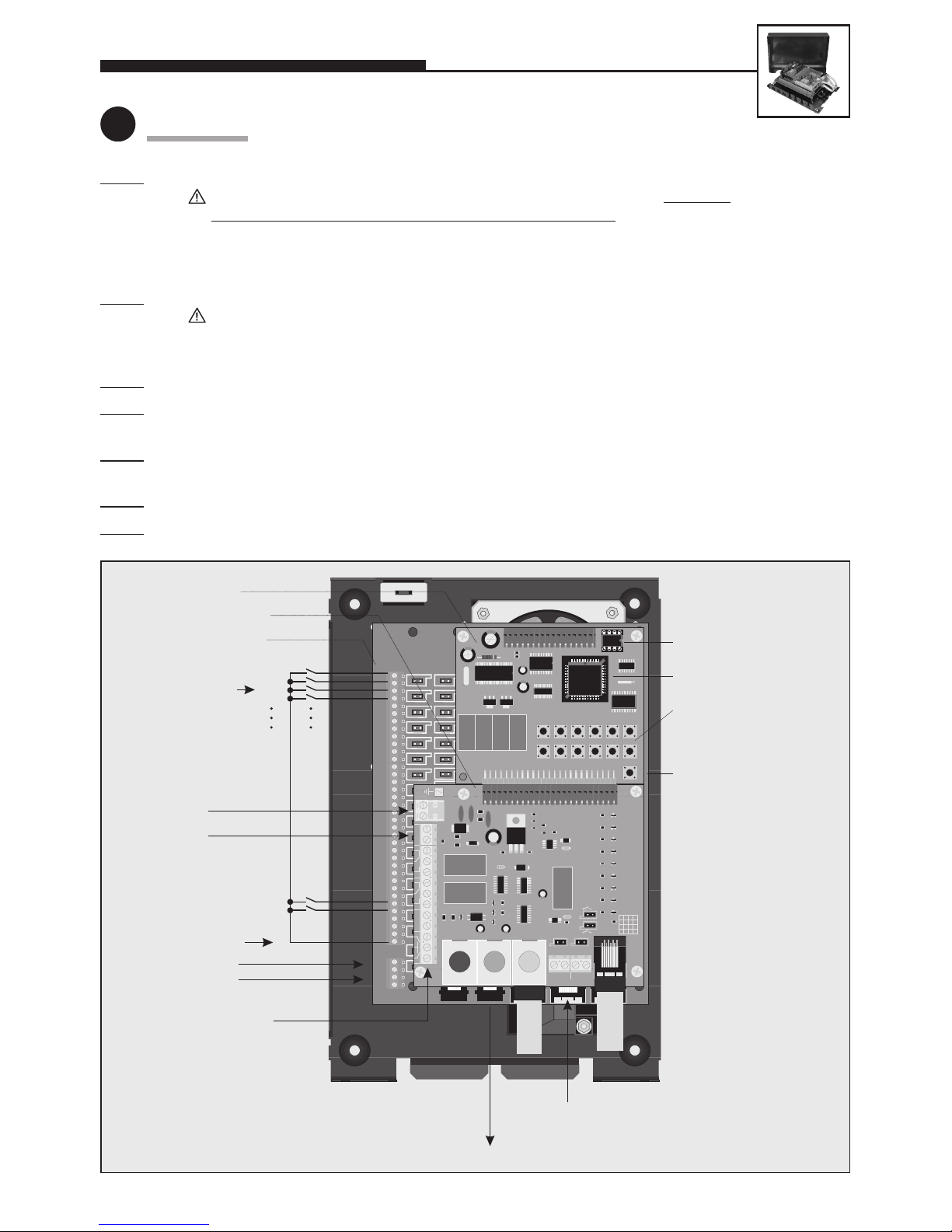
1
Connection
Step 1: Connect loudspeaker, microphone and buttons.
Distance of the loudspeaker, microphone and buttons from the basic unit: 100 m max
.
Buttons may hav
e a common return wire (applies only to 20-0007). To connect the basic electronics
package with the user-interface elements (loudspeaker, microphone and buttons) a shielded cable must
be used. IY-ST-Y or AY-ST-Y. Connect shield to –12 V terminal (see also Seite 2). Mount dial pad at a distance of 25 m max. (use Behnke patch cable for connecting the dial pad).
S
tep 2: Connect door opener to relay 1, if required.
Relay = voltage-free contact = only operates the door opener, without supplying it with electric energy;
the door opener requires its own power supply! Relay 2 is available for further switching functions
(see comprehensive technical manual; avalailable as PDF on the Internet).
S
tep 3:
Connect 12 V DC – required for 20-0007 (potential-free – use Behnke plug-in power supply 20-9500).
S
tep 4: Release both short patch cables connecting the upper with the lower board from the RJ45 jacks on the
upper board.
S
tep 5: Connect telephone line (a/b line from analogue PBX extension or analogue direct exchange line) => a long
beep signals the telephone’s operational readiness.
S
tep 6: Perform configuration (item 2), while observing configuration step 18.
S
tep 7: Correctly plug back in again the patch cables into the RJ45 jacks on the upper board.
Page 13
13
Standard settingEntry (code / parameter) Function
UNIVERSAL UNIT 20-0007
2
Configuration
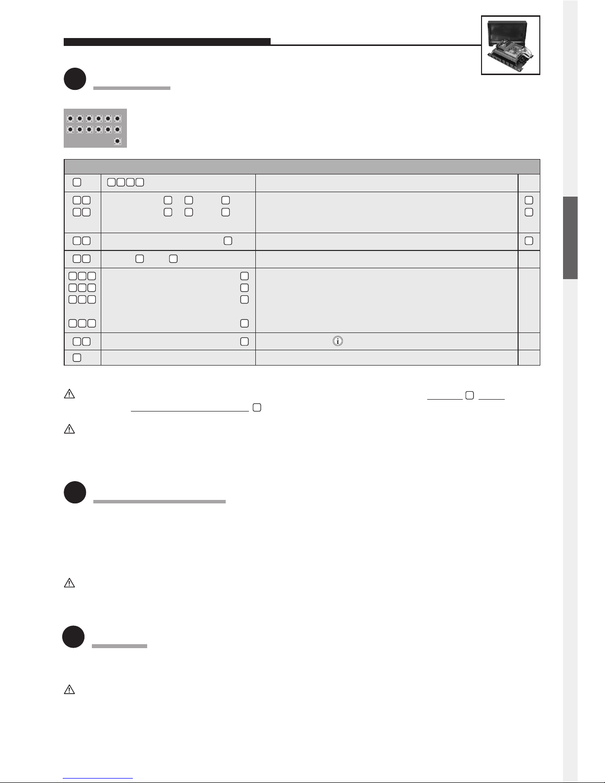
Use internal configuration keyboard (open universal casing for this purpose).
Alternatively, configuration can also be done by DTMF telephone (touch-tone telephone).
Configuration is only possible with the a/b line (telephone line) connected.
Following the entry of each phone number and other configuration steps, do not forget to press the button!
In each case, finish configur
ation mode with . Otherwise it is possible that your entry is not stored correctly!
(factory setting) Enable configuration mode
A button from to , then Volume; 0 = low, 9 = high (full-duplex mode)
A button from to , then Volume; 0 = low, 9 = high (with add-on amplifier)
Note: Preferably use values between 1 and 4.
Number (4-digits max.), then Door-opener code (= 1st code for controlling relay 1)
Button , then Activate power supply for the lower board —
Phone number to be dialled, then Phone number for 1 button —
Phone number to be dialled, then Phone number for 2 button —
Phone number to be dialled, then Phone number for 3 button —
:: :
Phone number to be dialled, then Phone number for 32 button —
Phone number to be dialled, then Phone number for button of the dial pad —
End configuration mode
12345
∗
67890#
∗
T
E
L
#
#
0 6 0 9
#
#
#
#
0
5
0
0
9
0 7
1 0
2 9
#
3 0 1
#
3 0 2
#
3 0 3
#
3 3 2
#
1 8 9
n
n
n
0 0 0 0
For further configuration steps (relay control, sound settings, voice-announcement/real-time clock extension electronics), please refer to our comprehensive technical manual (available as PDF on the Internet – see also note on page 2).
• Mount the universal electronics package in a weather-proof location and connect it to the user unit(s).
• Observe the notes on cabling on pages 12 and 13 (100 m max., shielded cables, etc.).
• The connected buttons must meet the requirements of EN 60950 for telecommunications network voltages (TNV) circuits.
Normal bell push buttons do not usually meet these requirements; if required, use Behnke button 20-9100.
Further mounting information (e.g. sample sketches or mounting with electronics extension 20-0057) can be found in
our comprehensive technical manual (available as PDF on the Internet – see also note on page 2).
The same operational notes apply as for Series 10 / Series 20 hands-free telephones (see page 8).
Further information on the operation of universal units can be found in our comprehensive technical manual (available
as PDF on the Internet – see also note on page 2).
3
Mounting / Installation
4
Operation
ENGLISH
Page 14
14
LIFT EMERGENCY TELEPHONES
optional:
20-9230 Outside-car speech
module w/ button for underneath the car
Emergency
communication
device on top
of the lift car
with outsidecar speech
module
20-0028
Lift emergency
telephone
Emergency
communication
device inside
the car with
microphone
(using the
existing
emergency
button)
Sound
projection from
the panel or
from above
Existing emergency button
in the car operating panel
(break or make contact) or
button 20-9100
20-9219
Speech module,
size 3
NOTRUF
20-9302 Patch cable, 5 m
20-9301 Patch cable, 3 m
12 – 24 V DC
Emergency power
supply, e.g.
20-9650 BNOS UPS
20-9501 BNOS battery
power supply
20-0030/20-0031
Machine-room/car telephone
EMERGENCY
TAE socket
NFF
Telephone connection
1
2
3
4
5
6
7
8
9
0
Notruf
Hotline
2
5
8
0
1
4
7
*
3
6
9
#
ABC
JKLGHI
PQRS TUV
DEF
MNO
WXYZ
R
M
IWV/MFV
220 V
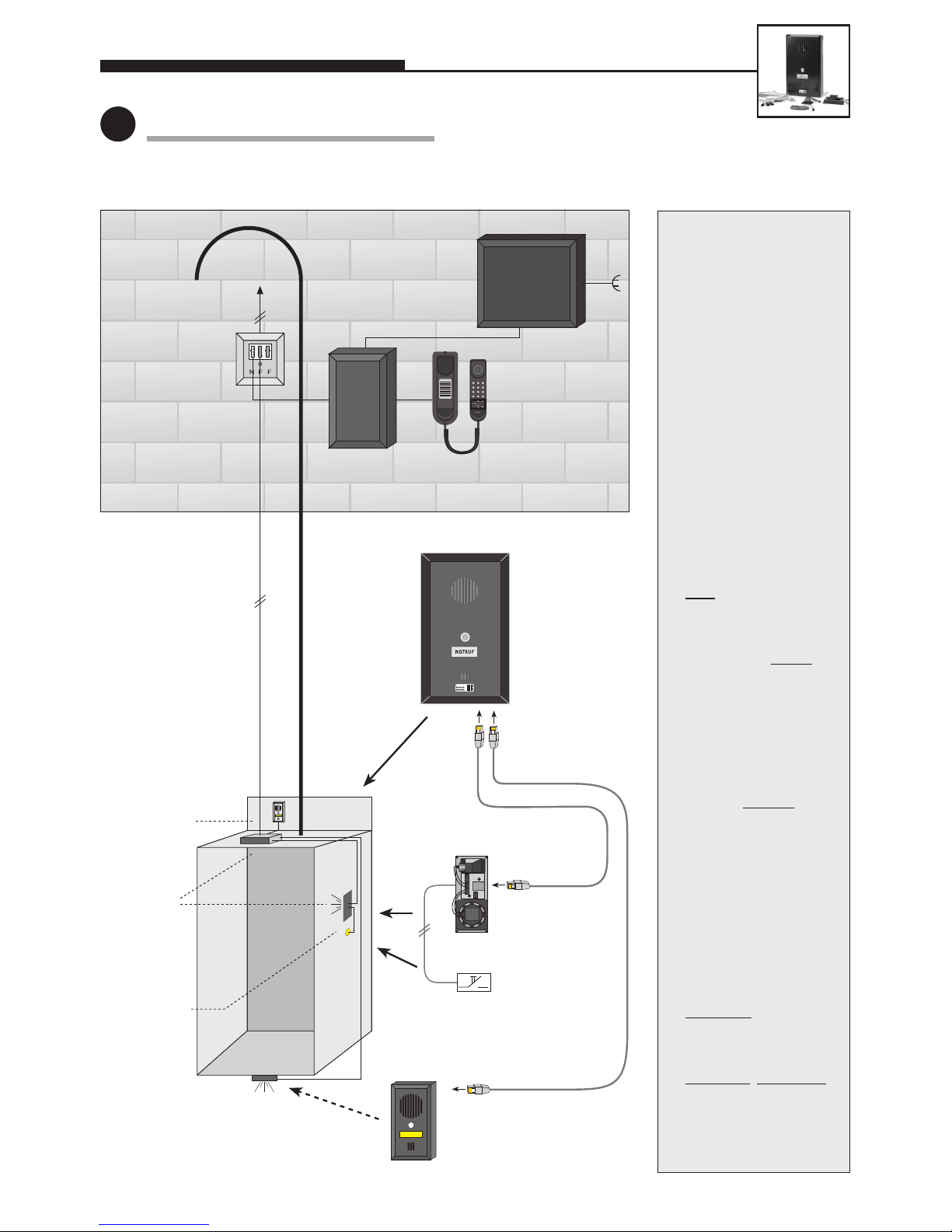
Lift emergency telephone with machine-room/car telephone
Notes:
1. The speech module, as
well as the rear-mount-
ing loudspeaker and
microphone require suf-
ficiently large sound
inlet and outlet holes
(see also page 2).
2. Rear-mounting compo-
nents must be mounted
flush
with the rear side
of the car operating
panel using a gasket
(important for good
sound quality). See also
note on page 2.
3. Keep the distance
between the micro-
phone and loudspeaker
as large as possible. See
also note on page 2.
4. For notes on mounting
B
NOS MCT (machine-
room/car telephone),
B
NOS UPS, BNOS hubs,
etc., refer to the corre-
sponding products.
1
Basic diagram of lift installation
Page 15
15
LIFT EMERGENCY TELEPHONES
2
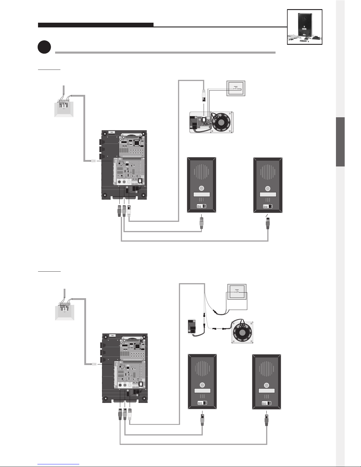
Basic diagrams with 3 MLMs (microphone/loudspeaker modules)
12345
∗
67890#
∗
T
E
L
#
Telefonbau Behnke GmbH
. 2
+ ALARM −
T1 T2
– 12V +
REL. 1
REL.
TEL
a / b
T1
T2
− MIC +
LS
− MIC +
LS
1
4
7
*
2
5
8
0
3
6
9i
#
+
\
\
+MLM C +MLM B
MLM A
rot blau gelb
2-m patch cable (blue)
5-m patch cable (red)
BNOS
outside-car
speech module with
button for on
top of the car
(MLM B)
Telephone connection
BNOS
outside-car
speech module
with button for
underneath the
car
(MLM C)
BNOS lift emergency
telephone
Connecting cable, RJ45 plug to 3x MQS plug, 3 m (yellow)
Rear-mounting microphone
and loudspeaker inside the
car; other modules are also
possible
(MLM A)
The emergency button present
in the panel is used for initiating
an emergency call
(make or break contact, see
configuration step 970).
T
L
M
The telephone-line cord is run from
the telephone socket in the
machine room along the
suspension cable to the emergency
telephone mounted on the car top,
to which it is connected.
EMERGENCY
EMERGENCY
12345
∗
67890#
∗
T
E
L
#
Telefonbau Behnke GmbH
. 2
+ ALARM −
T1 T2
– 12V +
REL. 1
REL.
TEL
a / b
T1
T2
− MIC +
LS
− MIC +
LS
1
4
7
*
2
5
8
0
3
6
9i
#
+
\
\
+MLM C +MLM B
MLM A
rot blau gelb
2-m patch cable (blue)
5-m patch cable (red)
BNOS outsidecar speech
module with
button for on
top of the car
(MLM B)
Telephone connection
BNOS outsidecar speech
module with
button for
underneath the
car
(MLM C)
BNOS lift
emergency
telephone
Connecting cable, RJ45 plug to 3x MQS plug, 3 m (yellow)
BNOS speech module with loudspeaker
and microphone to be mounted inside
the car
• uses existing emergency button
• other modules are also possible
(MLM A)
The emergency button present
in the panel is used for initiating
an emergency call (make or break
contact, see configuration
step 970).
The telephone-line cord is run from
the telephone socket in the
machine room along the
suspension cable to the emergency
telephone mounted on the car top,
to which it is connected.
EMERGENCY EMERGENCY
Sketch A: Lift telephone 20-0018 with speech module for rear mounting as MLM A
Sketch B: Lift telephone 20-0018 with microphone and loudspeaker for rear mounting as MLM A
ENGLISH
Page 16
16
LIFT EMERGENCY TELEPHONES
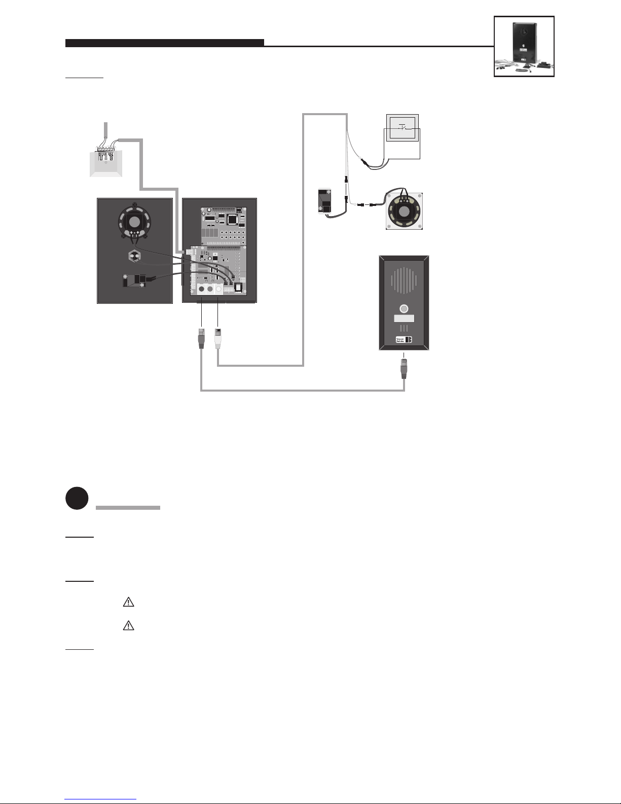
5-m patch cable (red)
Telephone connection
BNOS outsidecar speech
module with
button for
underneath the
car
(MLM C)
BNOS lift emergency
telephone 20-0028
with integrated
outside-car speech
module
Connecting cable, RJ45 plug to 3x MQS plug, 3 m (yellow)
Built-in microphone and built-in
loudspeaker inside the car;
other modules are also
possible
(MLM A)
12345
∗
67890#
∗
T
E
L
#
Telefonbau Behnke GmbH
. 2
+ ALARM −
T1 T2
– 12V +
REL. 1
REL.
TEL
a / b
T1
T2
− MIC +
LS
− MIC +
LS
1
4
7
*
2
5
8
0
3
6
9i
#
+
\
\
+MLM C +MLM B
MLM A
rot blau gelb
EMERGENCY
The emergency button present
in the panel is used for
initiating an emergency call
(make or break contact, see
configuration step 970).
T
L
M
The telephone-line cord is run from
the telephone socket in the
machine room along the
suspension cable to the emergency
telephone mounted on the car top,
to which it is connected.
Sketch C: Lift telephone 20-0028 (with integrated outside-car speech module for on top of the car)
with microphone and loudspeaker for rear mounting as MLM A
3
Connection
Step 1: – Connect loudspeaker, microphone and buttons for inside the car = MLM A.
–
Connect outside-car speech module for on top of the car, if required = MLM B (not in the case of 20-0028).
– Connect outside-car speech module for underneath the car, if required = MLM C.
S
tep 2: Connect 12 V DC, if required (must be potential-free – use BNOS UPS or existing emergency power supply in
conjunction with BNOS DC/DC converter).
Only required for: illumination, camera, integrated heating, integrated add-on amplifier, connecting 12 V
through to an MLM.
Not required for: telephone operation, including all functions.
S
tep 3: Connect telephone line (a/b line from analogue PBX extension or analogue direct exchange line) => a long
beep signals the telephone’s operational readiness.
The lift emergency telephone 20-0028 is available either as a single unit or in two sets:
20-0021 Set 1 = telephone 20-0028 plus external loudspeaker and microphone with all connecting cables.
20-0022 Set 2 = like set 1, but with 1 additional outside-car speech module for underneath the car.
Page 17
17
LIFT EMERGENCY TELEPHONES
12345
∗
67890#
∗
T
E
L
#
Telefonbau Behnke GmbH
– 12V +
REL. 1
REL. 2
+ ALARM −
T1 T2
TEL
a / b
T1
T2
− MIC +
LS
− MIC +
LS
1
4
7
*
2
5
8
0
3
6
9 i
#
+
\
\
+MLM C +MLM B
MLM A
red blue yellow
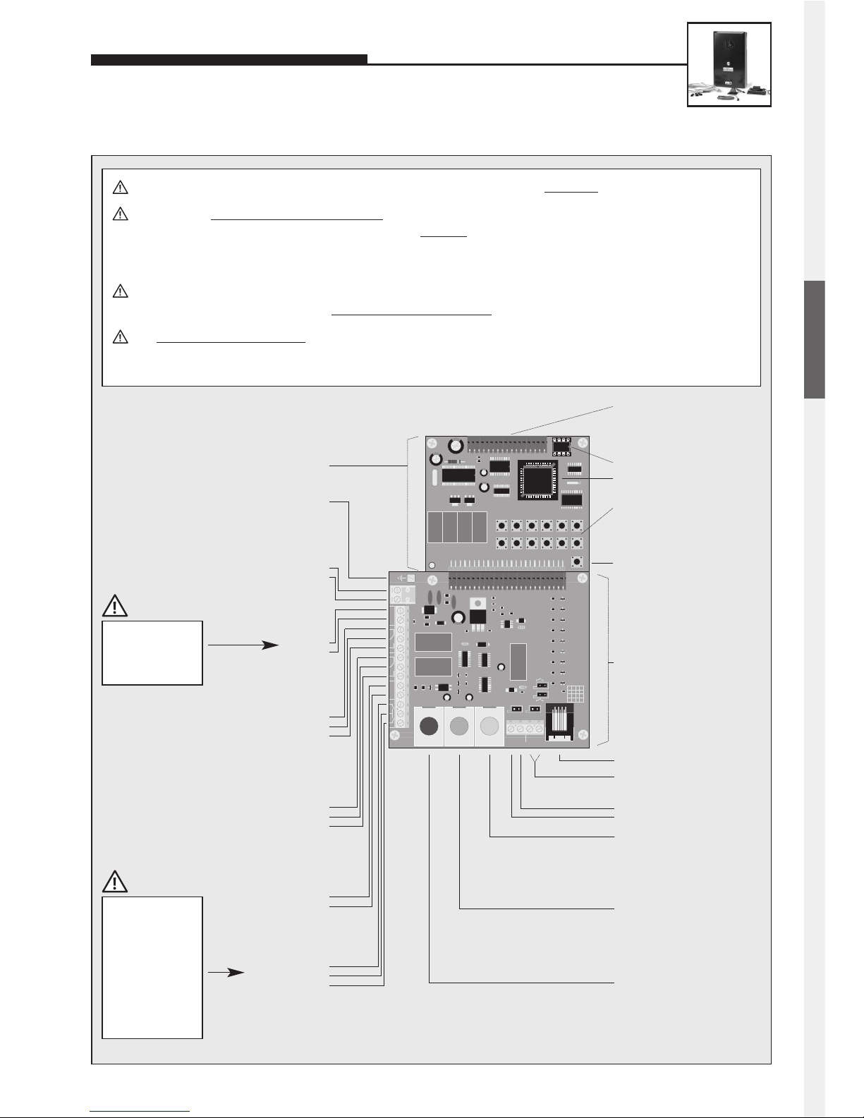
EEPROM
Master processor
Internal
configuration and
dialling keyboard
Earth
Main board
Connection board
Dial pad
Loudspeaker
Microphone
MLM A
= main MLM
inside the car
MLM B
= additional MLM
on top of the car
MLM C
= additional MLM
under the car
Telephone ‘ON’
Buttons
Make or break contacts may
be used as nonlocking buttons
T1 button
Common contact
T2 button
Note: The button
inside the car must be
connected to the T2
terminal.
+
–
yellow
blue
red
Program phone number
with configuration step 22
Program phone number
with configuration step 23
Program phone number
with configuration step 24
Note:
The board’s connectors are labelled in German:
While MLM and LS have the same meaning as
in English (i.e. microphone/loudspeaker module
and loudspeaker), T1 and T2 refer to button 1 and
button 2 (German ‘Taste’).
Additional power supply
12 V DC=
potential-free voltage, e.g.
provided by BNOS UPS (only
required for special functions)
–
+
Telephone line
analogue direct exchange
line or PBX extension.
a wire
b wire
Relay 1
Relay contact rating:
60 VA 24 W max.
0.5 A 120 V AC or 1 A 24 V DC
NC
Com.
NO
Relay 2
Relay contact rating:
60 VA 24 W max.
0.5 A 120 V AC or 1 A 24 V DC
NC
Com.
NO
Alarm input
Alarm condition is
active while voltage is
applied
6 to 24 V DC=
–
+
Connector for
electronics extensions
featuring a voiceannouncement facility,
a clock or a display
Connect shield for
microphone and
buttons to –12 V,
not to earth!
Standard = ‘make
contact’; if button
is to be used as a
‘break contact’, the
configuration must
be changed (see
comprehensive
technical manual;
available as PDF on
the Internet).
Distance of the loudspeaker, microphone and buttons from the basic unit: 25 m max.
Buttons must not hav
e a common return wire. To connect the basic electronics package with the user-interface
elements (loudspeaker, microphone and buttons) a shielded
cable must be used. IY-ST-Y or AY-ST-Y. Connect
shield to –12 V terminal (see also Seite 2). Mount dial pad at a distance of 25 m max. (use Behnke patch cable
for connecting the dial pad).
In order to connect MLM A to C (microphone/loudspeaker modules = user units comprising loudspeaker, microphone and button), you should use original Behnke patch cables
– see also page 10.
The integrated add-on amplifier (1 W) can only be activated for MLM A. The corresponding configuration steps can
be found in our comprehensive technical manual (available as PDF on the Internet – see also note on page 2).
ENGLISH
Page 18
18
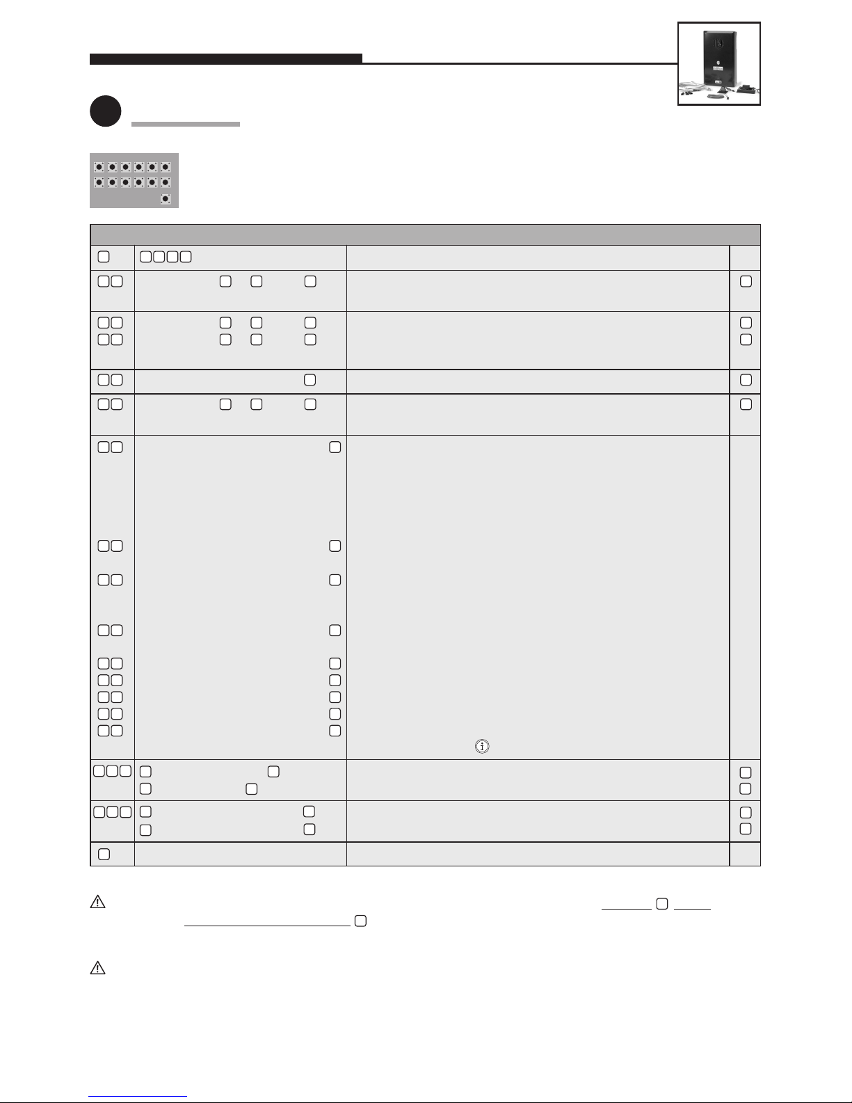
Standard settingEntry (code / parameter) Function
LIFT EMERGENCY TELEPHONES
4
Configuration
Use internal configuration keyboard (open universal casing for this purpose).
Alternatively, configuration can also be done by DTMF telephone (touch-tone telephone).
Configuration is only possible with the a/b line (telephone line) connected.
Following the entry of each phone number and other configuration steps, do not forget to pr
ess the button!
In each case, finish configur
ation mode with . Otherwise it is possible that your entry is not stored correctly!!
(factory setting) Enable configuration mode
A button from to , then Direct-Call Button Response Delay
0 = none, 1 = 1 second, 9 = 9 seconds
A button from to , then Volume; 0 = low, 9 = high (full-duplex mode)
A button from to , then Volume; 0 = low, 9 = high (with add-on amplifier)
Note: Preferably use values between 1 and 4.
Number (4-digits max.), then 1st code for controlling relay 1
A button from to , then Group Call / Redial / Undroppable Call:
Number of phone numbers to be dialled
Phone number to be dialled, then 1st phone number in case of redial or: —
– in the case of 20-0018: phone number of the
button connected to the T1 contact (microphone and
LS in the telphone active).
– in the case of 20-0028: phone number of the emergency button
on the telephone for initiation on top of the car (integrated MLM).
Phone number to be dialled, then Phone number for MLM A (yellow jack) = inside the car or button —
connected to T2 contact or 2nd phone number in case of redial
Phone number to be dialled, then Phone number for MLM B (blue jack) = on top of the car (not in —
the case of 20-0028, because MLM is integrated on top of the car!)
or 3rd phone number in case of redial
Phone number to be dialled, then Phone number for MLM C (red jack) = underneath the car or —
4th phone number in case of redial
Phone number to be dialled, then 5th phone number in case of redial —
Phone number to be dialled, then 6th phone number in case of redial —
Phone number to be dialled, then 7th phone number in case of redial —
Phone number to be dialled, then 8th phone number in case of redial —
Phone number to be dialled, then 9th phone number in case of redial —
or phone number for button of the dial pad —
= not allowed, then Only when configuration is allowed can the
= allowed, then following configuration step be performed
= as a make contact, then T2 operational mode
= as a break contact, then T2 operational mode
End configuration mode
12345
∗
67890#
∗
T
E
L
#
#
0 6 0 9
#
0 9
#
0 9
#
#
#
0
5
0
0
0
0
9
0 7
1 0
2 0
n
n
0 0 0 0
For further configuration steps (relay control, sound settings, voice-announcement/real-time clock extension electronics), please refer to our comprehensive technical manual (available as PDF on the Internet – see also note on page 2).
#
#
#
#
#
#
#
#
#
2 1
2 2
2 8
2 9
2 3
2 4
2 5
2 6
2 7
0 4
#
#
#
#
0 0
0
9
09
0
0
0
0
1
0
1
7
n
Page 19
19
LIFT EMERGENCY TELEPHONES
Basically, the same operational notes apply as for Series 10 / Series 20 hands-free telephones (see page 8).
Further operational information can be found in our comprehensive technical manual (available as PDF on
the Internet – see also note on page 2).
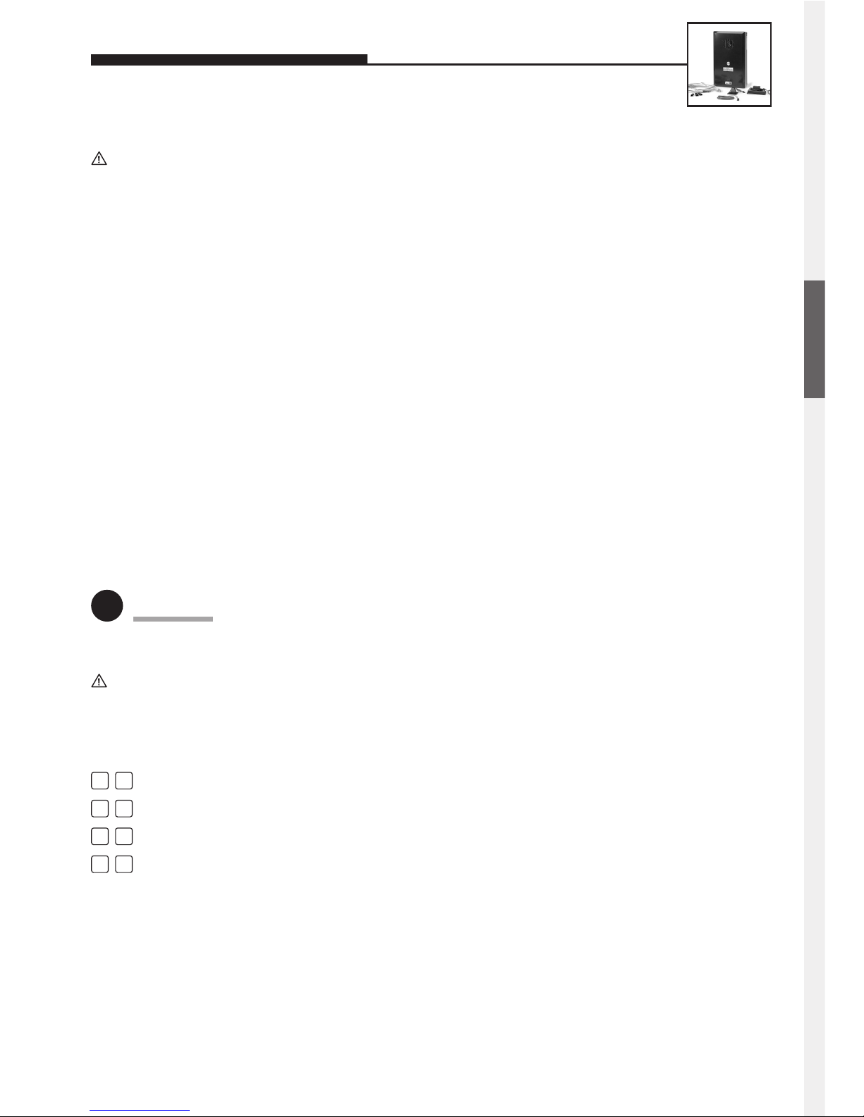
Switching between several microphone/loudspeaker modules (MLM A to C and integrated MLM):
Activate MLM B (MLM on top of the car; blue jack)
Activate MLM A (MLM inside the car; yellow jack)
Activate MLM C (MLM underneath the car; red jack)
Switch between MLM A (inside the car) and the integrated microphone in the BNOS lift emergency telephone
5
Operation
n
1
n
2
n
3
n
5
Make contact/break contact:
In some cases, lift emergency telephones require the possibility of connecting a break (normally closed) contact as an
emergency button. A break contact can only be connected if the parameter for this CS is set to 1. When you switch from
break contact to make contact or vice versa, the unit will be initialized automatically the next time a connection is
established and afterwards it will be ready for use.
Note: Usually there is no point in changing the parameter for this CS remotely, because after reconfiguration it would
be necessary to connect the corresponding button (break or make contact) to the T2 terminal.
How to Switch from Make to Break:
1. Put the unit with an attached make contact (or without any button attached) into configuration mode.
2. Enter CS 970 – 1.
3. End configuration mode.
4. Disconnect the make contact and connect the break contact to the T2 button.
5. The unit will turn itself on and initialize automatically.
How to Switch from Break to Make:
1. Put the unit with an attached break contact into configuration mode.
2. Perform configuration step 970 – 0.
3. End configuration mode.
4. Disconnect the break contact and attach the make contact to the T2 button.
5. The unit will turn itself on and initialize automatically.
ENGLISH
Page 20

20
FAULT TABLE
3 EEPROM fault • EEPROM is not correctly installed in the corresponding socket.
• EEPROM is defective.
4 Button matrix fault • Attached button, configuration button or dial-pad
button is stuck or defective.
• Connecting cable for button or dial pad is damaged.
• Interference.
• Moisture on board or in connecting plug.
5 Busy-tone decoder fault • Busy-tone decoder module is defective.
6 DTMF-tone decoder fault • DTMF-tone decoder module is defective.
7 1-kb EEPROM • Wrong EEPROM, v1.30 and higher only admit 2-kb EEPROMs.
(v1.30 and higher)
8 Microphone fault • Compact unit: wrong polarity of the attached microphone.
• Universal unit: wrong polarity of the microphone attached
to the integrated MLM.
9 Microphone fault • Wrong polarity of the microphone attached to the MLM A
of a universal unit.
10 Microphone fault • Wrong polarity of the microphone attached to the MLM B
of a universal unit.
11 Microphone fault • Wrong polarity of the microphone attached to the MLM C
of a universal unit.
Number Fault Possible Causes
of beeps
During initialization, the functionality of the main electronics components is checked. If a fault is detected in the
process, instead of the normal initialization beep you will
hear one of various sequences of beeps, each of which is
assigned to a specific fault. The following table shows these
assignments:
Page 21
21
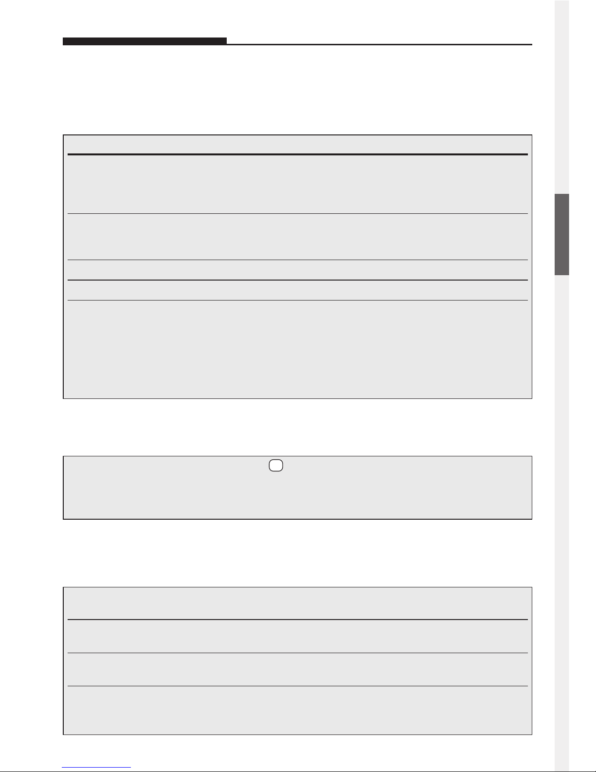
EXTENDED OPERATION
Entry Function
Activa- Activate relay
tion- In order to be able to activate a relay with an activation code, make sure that the relay’s
code # operational mode, its activation duration and, of course, its activation code are all set
correctly.
##x Set volume to value x (x = 0 to 9)
The setting of the volume only applies to the ongoing connection.
Setting the volume permanently is only possible with configuration step 06 or 07.
n# Hang up
nn Activate configuration mode (followed by entering security code)
n0 Switch between operation with and without add-on amplifier
1 OK beep Operation without add-on amplifier
2 OK beep Operation with add-on amplifier
Error beep Operation with add-on amplifier not possible or not allowed
Switching between operation with and without add-on amplifier is only possible if the addon amplifier has been activated with configuration step 07 and an additional 12-V DC power
supply has been attached.
During speech connection, the Behnke Telephone offers the following control options, which may be activated
with a touch-tone telephone:
1. Control options during a connection
n1 Activate MLM B
(If MLM B is not attached, this will activate the integrated MLM.)
n2 / n4 Activate MLM A
(If MLM A is not attached, this will activate the integrated MLM.)
n3 / n7 Activate MLM C
(If MLM C is not attached, this will activate the integrated MLM.)
n5 Switch between MLM A and integrated MLM
1 OK beep Integrated MLM activated
2 OK beep MLM A activated
3. The following commands are only possible, if several MLMs are attached:
(MLM = microphone/loudspeaker module)
2. Call Acceptance with ‘Redial / Group Call’ Activated:
Important: After lifting the handset, press the button to answer the call. Otherwise, the connection
will be broken automatically as ‘Redial / Group Call’ will proceed and the next number will be dialled.
DTMF telephone required (see configuration step 20 in the comprehensive technical manual – available
as PDF on the Internet).
#
ENGLISH
Page 22

22
SPECIFICATIONS
Type of connection: Analogue PSTN, a/b interface
Power supply: Via the a/b interface
Loop voltage: 20–70 V DC
Loop current: 20–60 mA
Additional power supply: 12 V DC potential-free +/–3 V, 500 mA max.
Note: Only necessary for illumination, camera, integrated heating, add-on amplifier or 12-V DC supply to MLMs (SELV, EN 60950)
Use the Behnke plug-in power supply 20-9500 or another additional power-supply
unit in conjunction with the Behnke DC/DC converter 20-9506 – each plug-in power
supply can have 1 Behnke Telephone attached to it.
Termination: ZRto TBR 21
Detected ringing signal: Cannot be specified exactly, since it depends on amplitude, frequency
and duration of the ringing signal.
Detected busy signal: 400–450 Hz sine wave
Detected busy signal duration: Signals with 160–700 ms tone and 160–700 ms pause, respectively
Maximum allowable cable length: 10 m each (for MLM A, +MLM B, +MLM C, LS, MIC, T1 and T2) or 25 m each
(for LS, MIC, T1 and T2, if no other MLM is attached)
Number of direct-call buttons: 96 max. (applies to 20-0007 with twice the electronics extension 20-0057)
Phone numbers: 20 digits max.
Dialling mode: DTMF, 50/50 ms (tone/pause)
Pause before dialling: 4 seconds
Duration of connection: 1–9 minutes and ‘unlimited’ (safety limit at about 8 hours)
Door-opener code: 2 codes with a maximum of 4 digits each (for each relay)
Door-opening duration: 1–30 seconds in 1-second steps
Door-opener contacts: 2 units (2 switching relays)
Relay contact rating: 60 VA 24 W maximum: 0.5 A 120 V AC or 1 A 24 V DC (resistive load)
Additional power supply to MLMs: Max. current load 30 mA for each MLM
Security code: 4 digits
Programming: Local programming by means of dial pad/integrated configuration keyboard.
Remote programming with DTMF telephone (touch-tone telephone).
Remotely programmable with BNOS control station.
Memory: EEPROM, nonvolatile
Tested to: TBR 21 and EG 201121 (EU-wide network access)
EN 55022, EN 55024 (Electromagnetic Compatibility)
EN 60950 (Electrical Safety)
Page 23
23
General Notices about our Products
and about this Quick Reference Guide:
• We reserve the right to make modifications to
our products in the interest of technical
progress.
Due to their continuous advancement, the products shown in the illustrations may also differ
optically from the products supplied.
• Texts, illustrations and photos from this quick
reference guide may not be reproduced in any
media (e.g. print, CD-ROM, Internet), in whole or
part, without our express written permission.
The design is copyright.
• We assume no responsibility for possible typo-
graphical errors, including those which might
occur in technical specifications or within illustrations and technical sketches.
Information on Product Liability Law:
• All products from our product range may only be
used for the indicated purpose. In case of doubt,
you should consult a competent expert or our service department (see Hotline numbers).
• All energized products (especially when 230-V
mains powered!) must be disconnected from the
power supply before they are opened or wired.
• Damages and consequential damages caused by
interference with or modifications to our products
as well as by misuse are excluded from liability.
The same is true for inappropriate storage or
other outside influences.
• Working with 230-V mains voltage or handling
mains- or battery-powered products requires
compliance with the relevant directives, such as
the Directive on Electromagnetic Compatibility
and the Low Voltage Directive.
Such work should only be carried out by an experienced specialist.
• Our products comply with all relevant technical
directives and telecommunications regulations
valid in Germany and the EU.
Electromagnetic
Compatibility
Low Voltage Directive
Our products are, of course, also certified according to the CE directives which are valid throughout
the EU, e.g. TBR 21 and EG 201121
(EU-wide network access).
LEGAL INFORMATION
ENGLISH
 Loading...