

Page 1
I
Corn
616
I
mander
N
1236
& 2260
Business Systems
I
-
In’stallation
&
Maintenance
Manual
This manual
contains propnetary
Information and IS to be
Issued
and used solely
withtn
Telecom
Australia
The manual was prepared by Standard Telephones and
Cables Pty Ltd for, and
In conjunct!on with.
Telecom
Australia
I
P
49
Telecom
Australia
Page 2

CONTENTS
1.
GENERAL
1
.l
INTRODUCTION
1.2 FACILITIES
1.3 OPERATING INSTRUCTIONS
1.4 SYSTEM CAPACITIES AND COMPONENTS
1.4.1 Systems Capacities
1.4.2 Systems Components
1.4.3 Block Diagram and Description
1.5 MECHANICAL DESCRIPTION
2.
INSTALLATION
2.1
INTRODUCTION
2.2 SALES INFORMATION
2.3 LOCATION AND MOUNTING OF EQUIPMENT
2.3.1 Main Equipment
2.3.2 Power Supply
2.3.3 System Distributing Frame
2.3.4 Stations
2.3.5 Powerfail Bell
2.3.6 Remote Extension and Tie Line Interface Unit
2.3.7 Call Metering Unit
2.3.8 Ring Generator Unit
2.4 CABLING AND TERMINATING METHODS
2.4.1 General
2.4.2 AMP Champ Connectors
2.4.3 S.D.F. Cabling
2.4.4 Lightning Protection
2.4.5 Exchange Lines
2.4.6 Earth Recall
2.4.7 Stations and DSS Console
2.4.8 Powerfail Stations
2.4.9 Powerfail Bell
2.4.10 Handsfree Console
2.4.1 1 Call Metering Unit
2.4.12 Remote Extension and Tie Line Interface Unit
2.4.13
E2WB-C and Ring Generator Unit (Internal Extensions)
2.4.14 External Music Source and Background Music
2.4.15 External Paging Loudspeakers
2.4.16 Alarm Detector
PAGE
1
3
7
29
29
30
35
41
49
50
57
58
58
59
61
62
62
63
63
64
64
64
65
73
74
74
74
75
76
76
78
79
80
81
81
81
N616,1236,2260
(i)
ISSUE 2
Page 3

CONTENTS
(Cont.)
PAGE
3.
MAINTENANCE
2.5 BOARD INSTALLATION INSTRUCTIONS
2.5.1 ELNB-A
2.5.2 ETSB-A and ETSB-B
2.5.3 ETSB-B and ETSB-C
2.5.4 ECMB-A, ECMB-B and ECMB-D
2.55
ESTB-C and EDTB-B
2.5.6 E2WB-C
2.5J
ECPB-A
2.6 POWERING UP THE SYSTEM
2.7 INSTALLATION PROGRAMMING
2.7.1 Programming Data
2.7.2 Checking Programmed Data
2.7.3 Modifying Programmed Data
2.7.4 Re-initializing Programmed Data
2.7.5 Facility Programming
2.7.6 Summary of Facility Programming and
2.8 FUNCTIONAL TEST
2.8.1
Exchange Line Test
2.8.2 Intercom Test
2.8.3 Station Test
2.8.4 DSS Console Test
2.8.5 Miscellaneous Tests
2.8.6 Internal Extension Test
2.8.7
RTIU
Tests
Initial Values
2.9
RECORDS
3.1
TEST EQUIPMENT AND MAINTENANCE AIDS
119
3.2 TEST POINTS
119
3.3 POWER SUPPLY INDICATORS
123
3.4 MAINTENANCE PROCEDURES
124
3.5 FAULT FINDING FLOWCHARTS
128
3.6 SUGGESTED REPAIR ACTIONS
173
3.7 REPAIR PROCEDURE
184
4. APPENDIX 1
Hardware Requirement Block Diagrams
Installation Parts Check List
Maintenance Parts Check List
Serial and Item Number Parts List
185
82
83
84
85
85
87
88
89
90
91
91
91
92
92
92
105
107
107
109
112
113
114
115
116
117
(ii)
N616,1236,2260
ISSUE 2
Page 4
’
1
GENERAL
1 .l INTRODUCTION
The N 616, N 1236 and N 2260 are electronic key telephone systems providing 6 exchange
lines and 16 stations, 12 exchange lines and 36 stations, 22 exchange lines and 60 stations,
respectively. They are a family of key telephone systems using common software and hardware
modules, packaged to provide various economical solutions. The stations have modern
functional styling.
The main equipment, stations and DSS console are controlled by micro processors with masked
programs providing a wide range of facilities demanded by the users of key systems.
A prominant feature of this equipment compared to previous key systems is the elimination of
multi-wire cabling in favour of 4 conductor
(2
pair) cabling.
*WARNINGS*
A.
This equipment contains a considerable number of MOS, and other static sensitive
components. To reduce the incidence of the premature failure due to static discharge, the
following precautions MUST be taken:
0
Always ensure that power is disconnected before plugging
PBAs.
0
Always discharge static from yourself by touching a conductive part of the main
equipment before handling boards.
0
Handle PBAs by the edge or by the handles. Do not handle PBA tracks, components
or edge connectors (contaminants introduced by fingers can cause corrosion and
high resistance connections).
0
Components are physically delicate. Finger pressure on a component can fracture,
but not necessarily break component leads: a future fault.
To protect against physical damage and damage due to static discharge,
PBA’s must
ALWAYS be wrapped in aluminium foil (e.g. cooking foil) and inserted into an
ANTI-STATIC plastic bag and placed in the protective container provided with the new
item. In the case of the ECMB remove the battery and package separately.
These procedures apply equally to both working and faulty PBA’s. Careless handling,
storage and transporting will cause secondary or future faults.
B.
To prevent the likelyhood of damage to electronic components, power should be switched
off before working on the systems.
.--
C.
The cabling between the Main Equipment and Stations is polarity sensitive. It is essential
that the correct polarity be maintained from the Main Equipment to the Stations and pairs
must not be swapped. Care must be exercised when checking voltages on cabling. Do not
short or bridge between terminals as this will cause fuses on the ESTB boards to blow.
WIRE
COLOUR
WT White
BL Blue
RD Red
BK Black
603 PLUG/
WIRE
610 SOCKET DESIGNATION
;
AL1
AL2
1
BD+
5
BD-
N616,1236,2260
1
ISSUE 1
Page 5
D.
Power supplies are powered from the 240 volt mains supply and hazardous voltages are
present within. Do not attempt to repair these devices in the field.
E.
ECMB- A,B, 8 D BOARDS
0
If these PBA’s are replaced, all site dependant data and abbreviated dial numbers are
lost. It will be necessary to re-programme the system.
0
The battery may be changed by removal of the daughter board (without loss of any
programmed data) with the ECMB power up, i.e. power on.
0
The press button
(SW4)
must be pressed to reset the crosspoints of the system after
replacing ESTB or ELNB boards when the power is on.
I
N616,1236,2260
2
ISSUE 1
Page 6
1.2 FACILITIES
1.2.1
INTERCOMMUNICATION BETWEEN STATIONS
Each station is able to establish an internal (intercom) call to another station by dialling the
desired stations number.
Automatic intercom line selection is provided, this requires only one Intercom Line Key per
station.
Assigned stations can call a particular station using a direct access key, Hot Line Key. In
addition, each system has a capacity for two Direct Station Select
(DSS)
Consoles
incorporating a Busy Lamp Field (BLF).
1.2.2 ALTERNATE POINT ANSWERING (CALL PICK-UP)
Any other station can answer an intercom call to another station by lifting the handset and
dialling the called stations number.
1.2.3
ADD ON CONFERENCE
A station may add another station onto an existing intercom call to set-up a three party intercom
conference using the ADD ON feature key.
1.2.4 BREAK-IN, OVERRIDE
Executive Break-in is provided by Hot Lines. Hot Line calls have priority over all other call types.
The DSS Console has priority to override an intercom call. An intrusion tone is signalled when
the DSS Console overrides a call. The DSS Console may be programmed to override stations in
Do Not Disturb.
I
1.2.5
DIRECT EXCHANGE LINE ACCESS
In general, any station can access any exchange line to answer an incoming call or make an
outgoing call. The only exception is exclusive lines.
Up to a maximum of 6 Exclusive Exchange Lines may be provided with the limitation of one per
station. An
ExecutiveSecretaiiaI
configuration can be arranged where only the secretary’s
station responds to
incomming
calls and the secretary may extend the calls to the executive
using an intercom call.
1.2.6
LAST NUMBER
REDIAL
The user may recall the last number
dialled
by operating the asterisk
‘*’
button after seizing an
exchange line and depressing-the Dial Control (DC) Key. When the system is connected to a
PABX via exchange lines, a 3 second pause is generated automatically when dialling through
the PABX.
1.2.7
MULTIPLE EXCHANGE LINE ANSWER
The status of each exchange line is displayed at every station facilitating the possibility of
answering an incoming call at any station. The exception being Exclusive Exchange Lines,
which only appear on one station.
1.2.8
CONFERENCE CALL (SIMULTANEOUS OUTSIDE LINE CALL)
A conferencing facility is provided which allows up to three internal stations to be connected to
an exchange line or, two exchange lines connected to an internal station.
1.2.9 COST CONTROL
Three forms of cost control are available. The systems can perform Access Barring by analysis
of
dialled
digits. Dialled digits are compared with codes preprogrammed into the system’s data
base. The system caters for 5 classes of barring.
Class A
-
Unrestricted
ClassB
-
Barred to ISD
ClassC
-
Limited allowed STD and ISD codes
Class D
-
Barred to STD
ClassE
-
Barred outgoing access when the system is installed behind a PABX.
N616,1236,2260
3
ISSUE 1
Page 7

The second form of cost control is the use of a Call Metering Unit which records the metering
pulses on an exchange line basis.
A third, but less useful, form of cost control is provided by a facility allowing No Access to a
group of Exchange Lines. This facility allows the exchange lines to be split into two groups and
selected stations are not permitted to make calls using exchange lines in the second group.
1.2.10
TIE LINES
By use of a Remote Extension and Tie Line Interface Unit the system can handle two types of tie
lines, Ring-in/Ring-out and Loop-in/Ring-out. The tie lines take the place of exchange lines.
1.2.11
PBX RECALL
Two methods of PBX Recall are available, Earth Recall or Switchhook Flash (Timed Loop
Break). The key for this facility takes the place of an exchange line key.
1.2.12 TRANSFER
A manual transfer is required when transferring an exchange line call. The station holds the
exchange line, notifies the other station using an intercom call and the station accepting the call
must seize the exchange line by operating the corresponding exchange line key.
The DSS Console may perform a Revertive Transfer. After calling the other station using a DSS
key the attendant may operate the Signal Call (SC) facility. The call is then signalled at the
transferred station. If the call remains unanswered after 20 seconds the call reverts to the DSS
station.
1.2.13 HOLD
Both manual and automatic hold are provided in the systems. Indications are provided for the
Hold, I-Hold and Exclusive Hold conditions.
Stations are provided with manual hold by operating the Hold Key, I-Hold is indicated at the
holding station and Hold is indicated at all other stations. A second operation of the Hold Key
will place the exchange line on Exclusive Hold, no other station can accept the call.
The DSS Console has an Automatic Hold, used when transferring exchange line calls to another
station. After answering an exchange line call the exchange line is automatically held when the
DSS attendant operates a DSS Key, an Internal/External Paging Key or the All Call Key.
1.2.14
CALL FORWARDING
Intercom calls and exclusive line calls are forwarded to a preassigned station after this facility
has been envoked by operating the Do Not Disturb Key at the unattended station. A maximum of
4 pairs of stations can have this facility.
1.2.15
ABBREVIATED
DIALLING
Each station is provided with a 16 number store with a capacity of 16 digits for each number
The station may store and recall numbers at any time.
1.2.16 PRIVACY
Privacy is provided for intercom calls as well as exchange line calls. The only exception is that
the DSS Console has the posibility to override a handsfree talk-back intercom call, following an
intrusion tone.
1.2.17 POWER FAILURE
When the power fails the exchange lines are automatically switched through to preassigned
stations set-up by the wiring of the connectors on the main equipment. In this condition the
preassigined stations can accept incoming calls and originate outgoing calls. All other facilities
are inoperative.
The system data base stored in CMOS memory is retained by a lithium battery.
1.2.18 AUTOMATIC RING BACK
When an exchange line is put on exclusive hold longer than a preset time the call is rung back to
the holding station.
4
N616,1236,2260
ISSUE 1
Page 8
1.2.19
NIGHT SWITCHING
Operation of the Night Transfer Key at a DSS Console directs ring signalling for all incoming
-.
calls to the programmed night transfer station(s).
1.2.20
MESSAGE WAITING
A visual indication is displayed at an unattended station to indicate that a message is waiting at
a DSS Console. A call to the DSS Console resets the message waiting indication.
1.2.21 SUPERVISORY TONES
The following supervisory tones are generated within the system:
Intercom Dial Tone
Busy Tone
Intrusion Tone
Number Unobtainable Tone
Ring Tone
1.2.22 MUSIC ON HOLD
Provision has been made for internally generated synthesized tones, or music from an external
source, to be transmitted to a caller who has been placed on hold.
1.2.23
BACKGROUND MUSIC
_~
Provision has been made so that music, supplied from an external source, can be transmitted
over the station speakers and external zone paging speakers, if required. The music can be
turned on and off at each station and is automatically turned off when the handset is off-hook.
1.2.24
PUSHBUTTON DIALLING
Each station is equipped with a push button pad. Dialling, Decadic or VF, is controlled by a
centralised dialling facility in the main equipment. A dialling station signals to the centralised
dialling facility via a data transfer and the decadic or VF signals are sent out on the exchange
line.
During power failure, powerfail stations have decadic or VF dials switched in at the station.
1.2.25
STANDARD TELEPHONES (P-WIRE INTERNAL EXTENSION)
It is possible to connect 2-wire standard telephones with decadic dialling using a special
interface card and a ring generator unit in place of a 4-wire station interface card.
1.2.26 REMOTE EXTENSIONS (REMOTE STATION, P-WIRE TELEPHONE)
A remote extension can be connected to the systems using a Remote Extension and Tie Line
Interface Unit which provides the 4-wire to 2-wire conversion, generation of ring voltages and
tones. The remote extension must be a decadic telephone.
1.2.27 VISUAL INDICATIONS
A visual indication is provided at each station to show the status of exchange lines (Free,
Incoming ring, Hold, I-Hold, Exclusive Hold and Busy), intercom lines (Free, Busy and
Microphone on), and system facilities (Do Not Disturb, Monitoring, Message Waiting
etc).
The
DSS Console has a Busy Lamp Field
(BLF)
which displays the status of each station in the
system. In addition the DSS Console displays the number of the station(s) holding held
exchange lines.
1.2.28 MONITORING (ON-HOOK
DIALLING)
Each station may originate and monitor the progress of a call using the station speaker without
lifting the handset.
1.2.29 HANDSFREE
TALKBACK
ON INTERCOM CALLS
The called party has a full handsfree facility when called via an intercom call. A single tone
announces the call and the voice of the calling party is heard through the station speaker, at the
same time the called station’s microphone is activated and the intercom status lamp flashes to
indicate the microphone is on. The microphone may be cut-off by operation of the DND key.
A volume control is used to adjust the sound level transmitted through the station speaker.
N616,1236,2260
5 ISSUE 1
Page 9

1.2.30 PAGING CALLS
Three paging facilities are provided, All Call, Internal Zone and External Zone Paging.
ALL CALL PAGING transmits an announcement over the station speakers of all stations and
through the external loudspeakers.
INTERNAL ZONE PAGING calls can be made through station speakers to one of four zones.
Stations are programmed to be in one of the four zones when the system is installed.
EXTERNAL ZONE PAGING calls are broadcast over external loudspeakers.
1.2.31 MEET-ME PAGING
The systems provide a facility which allows a person being paged to respond by simply lifting
the handset of any station through which the announcement was heard and pressing the “8”
button to be automatically connected to the caller. The caller must have pressed the asterisk ‘*’
button following the announcement.
1.2.32 FULL HANDSFREE OPERATION
Full handsfree operation is possible by adding a Handsfree Console to a station. This provides
handsfree operation at that station for every type of call.
1.2.33 CALL SIGNALLING
Incoming calls are signalled by a tone caller through the station speaker. Different signals are
provided for intercom calls and exchange line calls. Each station may be programmed to signal
when there is an incoming call on any exchange line or only on a group of exchange lines or it
may not signal for incoming exchange line calls. The volume control provides a means of
adjusting the volume of the tone caller.
1.2.34
ALARM SIGNALLING AT THE DSS CONSOLE
A supervisory or alarm device, which has as an output a set of contacts which open or close,
can be connected to the system. When the device is activated a flashing LED and audible alarm
signal will be indicated at the DSS Console. While in night transfer mode the alarm will be
indicated at the night transfer station(s).
1.2.35 DO NOT DISTURB
The system can provide a Do Not Disturb facility for all stations depending how the system is
programmed. Operation of the DND key puts the station in Do Not Disturb mode. This will turn off
the background music, block all paging calls, send busy tone to intercom callers, stop audible
signalling and forward calls to another station if so programmed.
1.2.36 KEY LABELS
The keys have transparent plastic covers which can be removed by hand so that a typed or
handwritten label may be placed under the cover for easy key identification.
1.2.37
SIGNAL CALL
If after placing an intercom call in the usual manner, there is no immediate response, the call
can be signalled using ring signalling by dialling an extra digit. The caller will hear ring tone and
the called party must answer by lifting the handset and operating the ICM Key.
1.2.38
PRESELECTION
A user may preselect the facility that is to be used by operating the facility key and then lifting
the handset off-hook, providing the handset is lifted within 5 seconds.
1.2.39 CALLS TO BUSY STATIONS
While a station is off-hook and busy on a call, muted incoming audible signalling may be heard
through the station speaker, depending on system programming. In this case the user may
decide to hold the exchange line he is using and accept the incoming call.
1.2.40
NUMBER PLAN
The systems have a fixed numbering scheme. Stations are numbered from 20 up to the
maximum system size 35
(616),55
(1236) and 79 (2260).
N616,1236,2260
6
ISSUE 1
Page 10
1.3 OPERATING INSTRUCTIONS
CONTENTS
1.3.1
1.3.2
1.3.3
1.3.4
STATION NOMENCLATURE
STATION LED INDICATIONS
SYSTEM TONES
STATION OPERATIONS
Placing an Exchange Line Call
Last Number Redial
On-hook Dialling
Abbreviated Dialling
Answering an Exchange Line Call
Holding an Exchange Line
Automatic Ring Back
(P.0)
Transferring an Exchange Line Call
Multi Party Conference (Exchange Line)
Listen-in Monitoring
Switchhook Flash
(P.0)
Earth Recall
(S.0)
Exclusive Line
(S.0)
Hot Line Call
(S.0)
Preselection
Placing an Intercom Call
Signal Call
Answering an Intercom Call
Alternate Point Answering
Calls to a DSS Console Attendant
Three Station Intercom Conference
Do Not Disturb
(P.0)
Call Forwarding
(P.0)
Microphone Cut-off
Paging All Call
Internal
(P.0)
External
(S.0)
Meet-me Answer Paging
(P.0)
Message Waiting
Background Music Control
Power Failure
(S.O.)
SYSTEM OPTION, requiring additional hardware
(P.O.)
PROGRAMMABLE OPTION, depends on system configuration
1.3.5
1.3.6
1.3.7
DSS CONSOLE NOMENCLATURE
DSS CONSOLE LED INDICATIONS
DSS CONSOLE OPERATIONS
DSS Call
Automatic Exchange Line Hold
Digits Display
DSS Override
(P.0)
Automatic Ring Back
Signal Call
Message Waiting
Night Transfer
Alarm Indication
(S.0)
Battery Low Condition
1.3.8 OPTIONAL EQUIPMENT
Handsfree Console
Internal Extensions (Internal Stations)
Remote Extensions (Remote Stations)
Tie Lines
1.3.9
QUICK REFERENCE TABLE
N616,1236,2260
7
ISSUE 1
Page 11
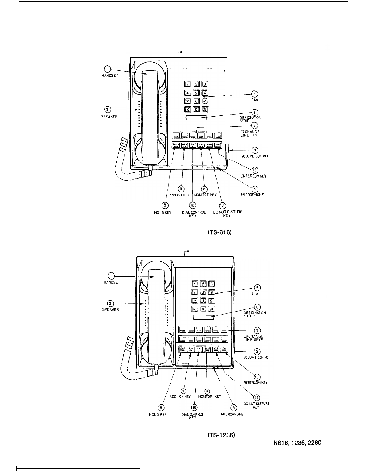
1.3.1
STATION NOMENCLATURE
o--
HANDSET
-
SPEAKER
-
HANDSET
o----
SPEAKER
d
0
6
10
b
12
------a
DIAL
------a
;F;FNATlON
------a
EXCHANGE
LINE KEYS
HOLD
KEV
DIAL CONTROL
DO
NOT DISTURB
KEY
KEY
FIGURE 1 N616 STATION (TS-616)
l-l
h
b
13
INTERCOM
KEY
\o
I
MICROPHONE
I
d ADD
AEVlMOkR
KEY
1 bs;lE
HOLD
KEY
DIAL CONTROL
MICROPHONE
KEY
EXCHANGE
LINE KEYS
FIGURE 3 N1236 STATION (TS-1236)
8
N616,1236,2260
ISSUE 1
Page 12
HANDSET
1
?
1.
2.
3.
4.
5.
-
6.
7.
a.
9.
10.
11.
12.
13.
DO NOT
DISTURBKEY
VOLUME
CONTROL
d
Q
b
HOLD KEY
‘NTKEERyCoM
MICROPHONE
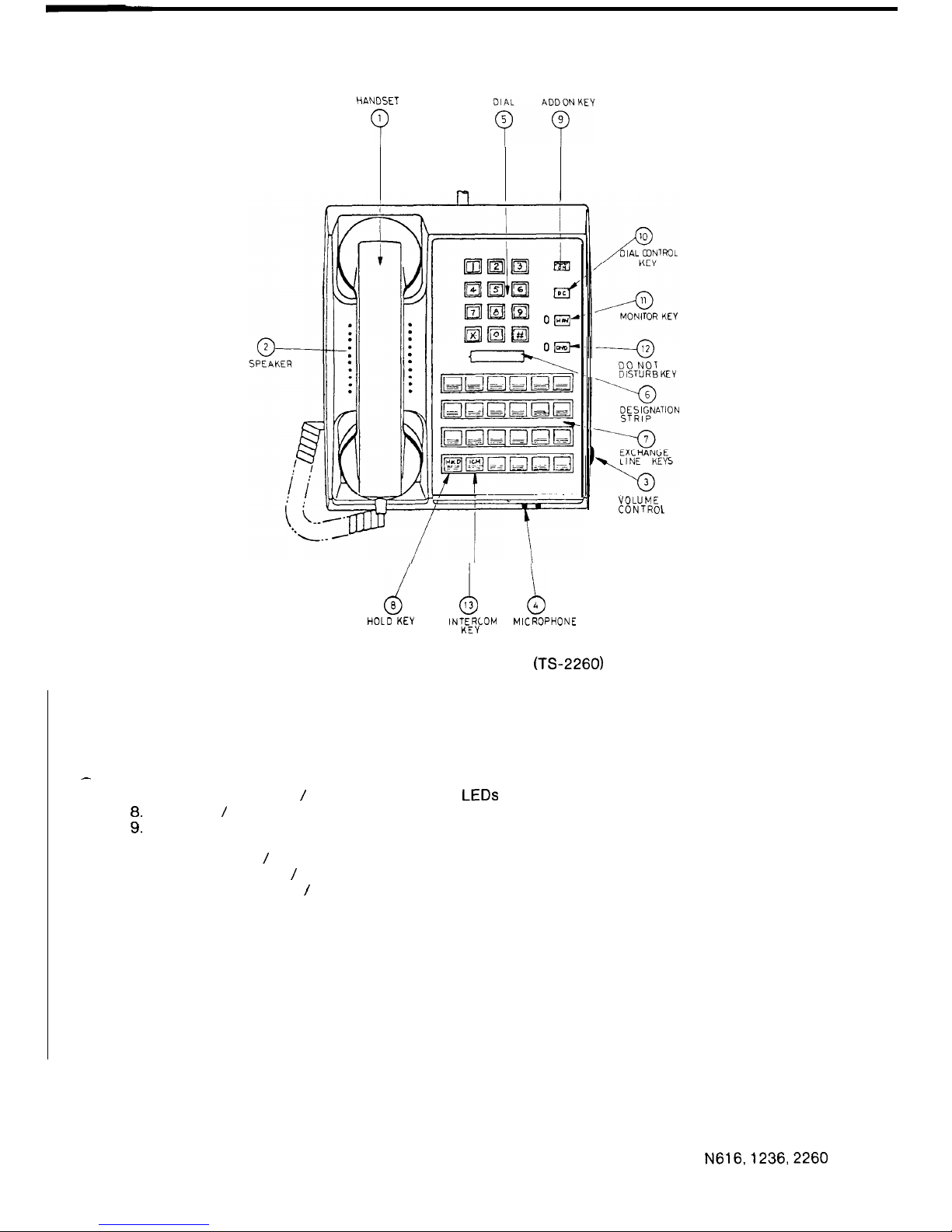
FIGURE 3 N2260 STATION (TS-2260)
Handset
Station Speaker
Volume Control
Microphone
Push-button Dial
Desighation Strip
Exchange Line Keys / Exchange Line Status LEDs
Hold Key / Message Waiting LED
Add On Conference Key
Dial Control Key
Monitoring Key / Monitoring Status LED
Do Not Disturb Key / Microphone Cut-off Key
Intercom Control Key / Intercom Status LED
When the system provides an Exclusive Line, Hot Line and Earth Recall or Switchhook Flash
the keys used for these facilities are automatically allocated. The last three exchange line keys
will be used depending on what facilities are required.
The keys are allocated as shown:
616
1236 2260
-4 -10 -20
Exclusive Line Key
-5
-11 -21 Exclusive Line Key or Hot Line Key
-6
-12 -22
Exclusive Line Key or Hot Line Key or Earth Recall Key or
Switchhook Flash Key
The exchange line keys are allocated from the last key to the third last key. If two facilities are
used, for example Exclusive Line and Earth Recall the Exclusive Line will be allocated to the
second last exchange line key.
Note:
If the system is fully equipped with exchange lines, then the station has lost the use of
the last common exchange lines.
N616,1236,2260
9
ISSUE 1
Page 13
I
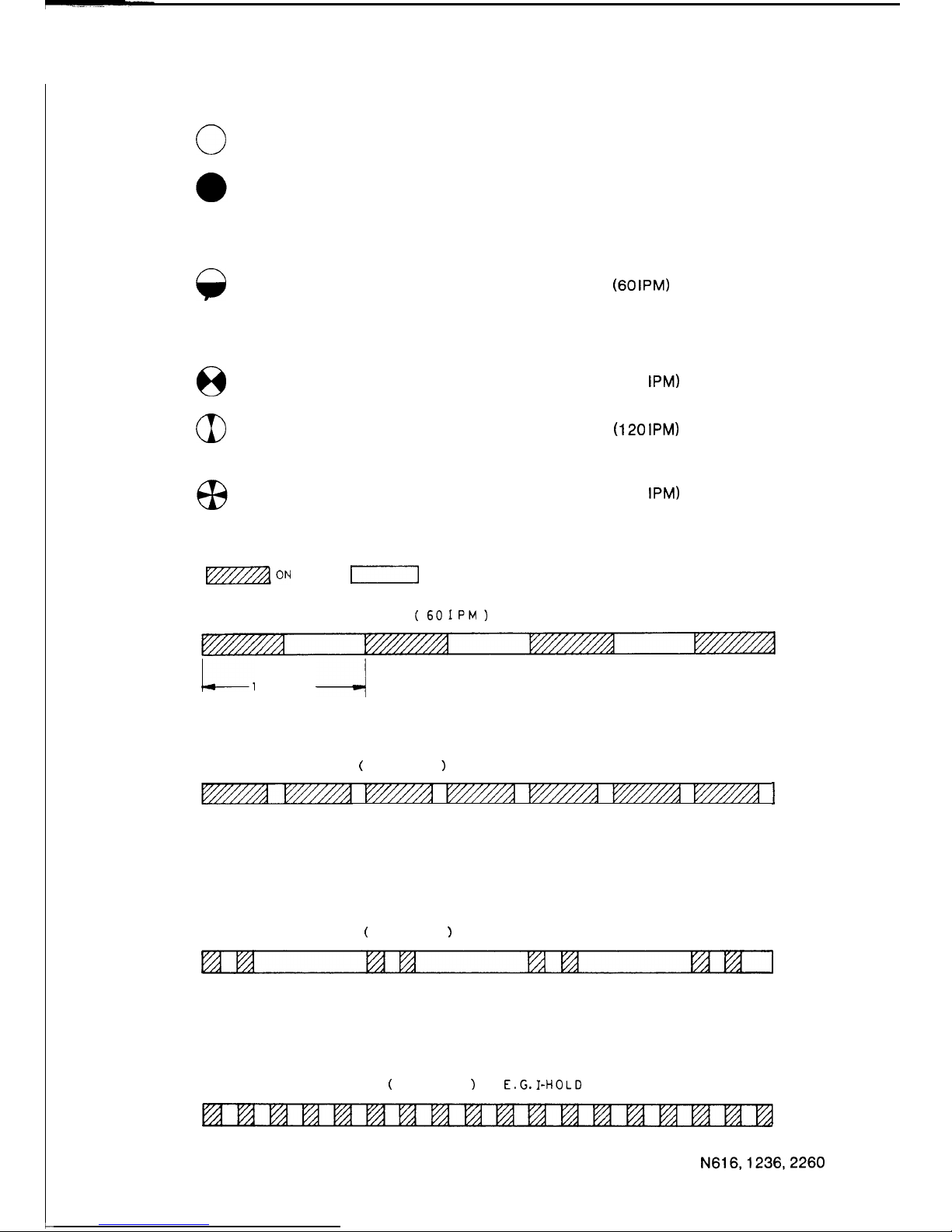
1.3.2 STATION LED INDICATIONS
c
0
Off
Steady
A
Slow Flash
8
Flash
aI
Flicker
Rapid Flash
l7zzzzaON
Free
Busy
On-Hook Dialling
Do Not Disturb
Listen-in Monitoring
Incoming Call
(60
IPM)
Intercom Call (Microphone off)
Microphone Off
Message Waiting
Hold
Exclusive Hold
Add On Standby
(120 IPM)
(120 IPM)
I-Hold
(300 IPM)
Intercom Call (Microphone on)
Hot Line Call
Automatic Ring Back
I-]
OFF
SLOW
FLASH
(601PM)
E.G. INCOMING CALL
Ll
SECOND
-/
FLASH
(
120 IPM
)
E.G.
HOLD
I
FLICKER
(
120 IPM
)
E.G. EXCLUSIVE HOLD
RAPID FLASH
(
300 I P M
1
E.G.I-HOLD
FIGURE 4 LED INDICATIONS
N616,1236,2260
10
ISSUE 1
Page 14
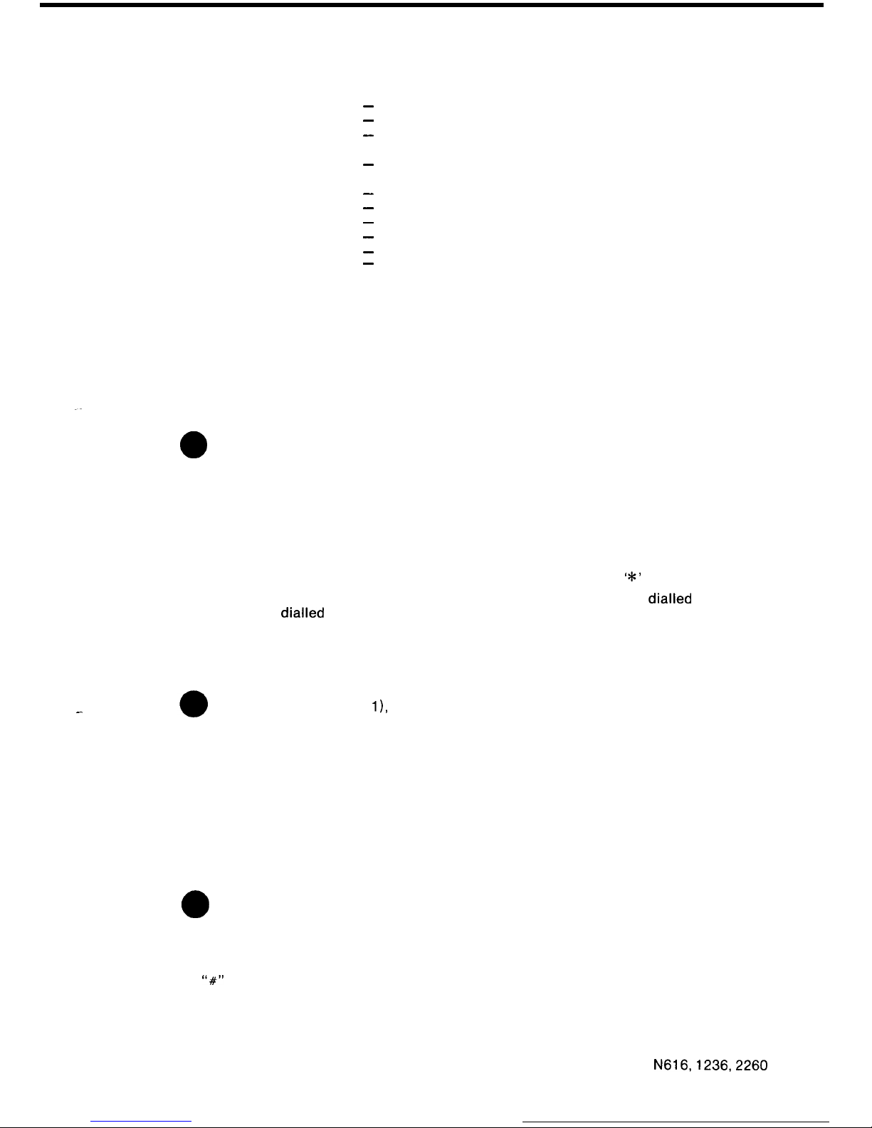
1.3.3 SYSTEM TONES
Ring Tone
Constant Tone
Slow Repeating Tone
(60 pulses per minute)
Fast Repeating Tone
(120 pulses per minute)
Single Tone Burst
Double Tone Burst
Single Warbling Tone
Repeating Warbling Tone
Five Tone Bursts
Rapid Repeating Tone
(300 pulses per minute)
-
Signal Call
-
Dial Tone
-
Station Busy
Paging Busy
-
Station in Do Not Disturb
Number Unobtainable Tone
-
Intercom Call to Station with Mic on
-
Intercom Call to Station with Mic off
-
Paging Call
-
DSS Intrusion Tone
-
Hot Line Call
-
Alarm Signal
1.3.4 STATION OPERATIONS
PLACING AN EXCHANGE LINE CALL:
Lift the Handset (1) and press a free Exchange Line Key (7).
Dial the desired number after receipt of Dial Tone.
.-
The selected Exchange Line Status LED (7) indicates:
a
Busy condition at all stations.
No other station can come across this line. You have complete privacy.
LAST NUMBER REDIAL:
Lift the Handset (1).
Select a free Exchange Line Key (7).
When you hear Dial Tone, press the DC (Dial Control) Key (10) then press the
‘*’
button.
The system automatically dials the last number called. A
pause
a PABX (i.e. if you first
dialled
the digit for an outside line).
is inserted if you
dialled
through
ON-HOOK DIALLING:
To initiate a call without lifting the Handset (1);
-
Press the MON Key (1
l),
Select a free Exchange Line Key (7) and dial the required number.
Once the person being called answers the telephone, you must lift the Handset (1) off-hook to
speak.
ABBREVIATED DIALLING:
STORING TELEPHONE NUMBERS
Lift the Handset (1).
Press the DC Key (10) and wait for Dial Tone.
a
The ICM Status LED (13) will light.
Assign the storage location by dialling a number from 10 to 25.
Then dial the desired telephone number. If a pause is required within the telephone number
press the
“#‘I
button and continue entering the remaining digits.
Up to 16 digits may be stored including any pause.
To store further abbreviated dialling telephone numbers, press the DC Key (10) and repeat the
above procedure. Place the Handset (1) on-hook when you have finished.
N616,1236,2260
11
ISSUE 1
Page 15
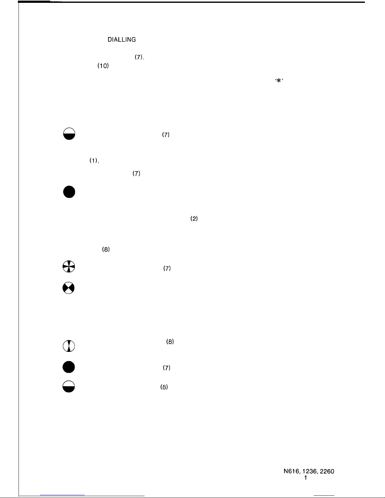
USING ABBREVIATED DIALLING
Lift the Handset (1).
Select a free Exchange Line Key
(7).
Press the DC Key
(10)
and dial the abbreviated number (from 10 to 25) corresponding to the
telephone number you wish to dial.
When dialling stops due to a pause, wait for the new dial tone, then press the
‘*’
button to
continue dialling the abbreviated number.
ANSWERING AN EXCHANGE LINE CALL:
Incoming calls are signalled by a Tone Caller (if assigned) through the Station Speaker (2) and
the
0
Exchange Line Status LED
(7)
slow flashes at all stations.
To answer the call,
Lift the Handset
(11,
Press the Exchange Line Key (7).
The Exchange Line Status LED
(7)
then indicates:
0
Busy condition at all stations,
Should an exchange line call come for your station while it is in the busy condition, off-hook ring
signalling will be heard through the Station Speaker
(2)
if this option is assigned.
Once the call is answered, no other station can come across the line.
HOLDING AN EXCHANGE LINE:
Press the HOLD Key
(6)
once. The
a3
Exchange Line Status LED
(7)
on your station will indicate
8
HOLD condition is indicated on all other stations.
If provided, music is transmitted to the held line.
I-HOLD.
To release the exchange line from Hold, any station may press the Exchange Line Key (7)
corresponding to the held line.
aI
Pressing the “HOLD” Key
(6)
twice puts the exchange line on EXCLUSIVE
HOLD. In this condition only the station which held the line may answer the line.
0
Exchange Line Status LED
(7)
indicates busy at all other stations.
8
The LED in the HOLD Key
03)
may indicate Message Waiting.
AUTOMATIC RING BACK (PROGRAMMABLE OPTION):
Once an exchange line has been on Exclusive Hold for a preset time, the Tone Caller signals
again. If the call is not answered after a further 20 seconds the DSS station will ring.
12
N616,1236,2260
ISSUE
1’
Page 16
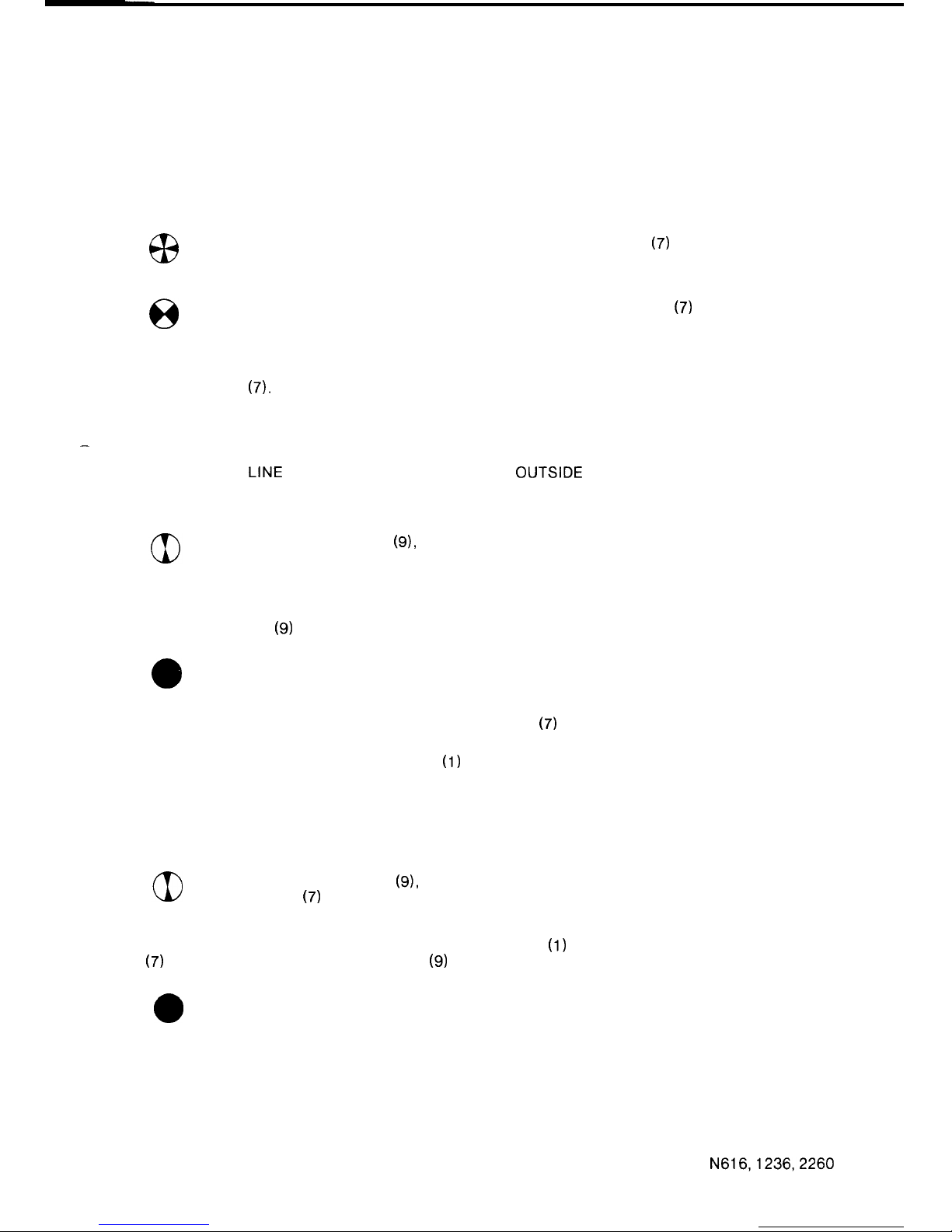
TRANSFERRING AN EXCHANGE LINE CALL:
Vocal Transfer
Hold the Exchange Line and advise the required person to pick-up the call.
Transfer by Intercom or Paging Call
Place the call on hold and inform the required person via an intercom or paging call as
described in Placing an Intercom Call and Paging.
I-HOLD is indicated on the held Exchange Line Status LED
(7)
at the holding
station and the
0
HOLD condition is indicated on the Exchange Line Status LED
(7)
at all other
stations.
The transferred call is answered by lifting the Handset (1) and pressing the corresponding
Exchange Line Key
(7).
-
MULTI PARTY CONFERENCE (EXCHANGE LINE):
Two EXCHANGE LINE CONFERENCE (SIMULTANEOUS OUTSIDE LINE CALLS)
While talking on an exchange line call,
Press the ADD ON Key
(9),
the exchange line is held and the Exchange Line
Status LED (7) indicates Add On Standby.
Place another call using a free exchange line and begin the conversation.
Press the ADD ON Key
(9)
again to begin the conference.
0
Both Exchange Line Status Lamps (7) indicate busy.
To release one exchange line press the Exchange Line Key
(7)
corresponding to the person to
whom you wish to continue to converse.
To terminate the conference place the Handset
(1)
on-hook.
TWO OR THREE STATION CONFERENCE WITH AN EXCHANGE LINE (OUTSIDE CALL
CONFERENCE)
While talking on an exchange line call,
Press the ADD ON Key
(9),
the exchange line is held and the Exchange Line
Status LED
(7)
indicates Add On Standby.
Ask the desired person, if located nearby, to lift the Handset
(1)
and press the Exchange Line
Key
(7)
you are using. Press the ADD ON Key
(9)
again to begin the conference.
a
The Exchange Line Status LED (7) indicates busy.
13
N616,1236,2260
ISSUE 2
Page 17
Alternatively, the station which is to join the conference may be called via the intercom.
When the intercom call is answered, ask the person called, to lift the Handset (1) and press the
ICM Key (13) or the Exchange Line Key (7) you are using. Press the ADD ON Key (9) again to
begin the conference.
0
The Exchange Line Status LED (7) will indicate busy.
If the intercom call is not answered, press the ADD ON Key (9) to continue the conversation.
Up to 3 stations can be in conference with an exchange line, each station is added to the
conference using the above procedure.
LISTEN-IN MONITORING:
Once a call is established and you wish to listen-in, but not take part in the conversation.
a
Press the MON Key (11) and then place the Handset (1) on-hook.
The received voice signal will be heard through the Station Speaker (2).
To stop monitoring, press the MON Key (11) again, or lift the Handset (1).
SWITCHHOOK FLASH (PROGRAMMABLE OPTION):
This facility is provided only when the system is connected to a PABX which uses Voice
Frequency dialling.
While on a local call via the PABX press the Switchhook Flash Key to hold the exchange line at
the PABX. Operation of the Switchhook Flash Key will give loop break of 1 second.
The Switchhook Flash Key is allocated as follows:
616 Exchange Line 6
1236
Exchange Line 12
2260 Exchange Line 22.
EARTH RECALL (SYSTEM OPTION):
This facility is provided only when the system is connected to a PABX which uses decadic
dialling.
While on a local call via a PABX press the RECALL Key to hold the exchange line at the PABX.
Operation of the Recall Key will put an earth on the line for 1 second.
In some cases the RECALL Key may be used to call the PABX operator.
The RECALL Key is allocated as follows:
616 Exchange Line 6
1236 Exchange Line 12
2260
Exchange Line 22.
EXCLUSIVE LINE (SYSTEM OPTION):
Only one station is connected to an Exclusive Line. Operation of an Exclusive Line is the same
as the operation of an exchange line, as described above.
The exceptions being; an Exclusive Line can not be transferred and access barring is not
applied to an Exclusive Line.
An Exclusive Line may be one of the last three Exchange Line Keys (7).
14
N616,1236,2260
ISSUE 2
Page 18
HOT LINE
CALL(SYSTEM
OPTION):
Only two stations are connected to a Hot Line.
To call the other station,
Lift the Handset
(l),
and press the Hot Line Key.
0
The Hot Line Status LED indicates busy.
To answer a Hot Line call, the
a3
Hot Line Status LED indicates a call.
Lift the Handset
(l),
and press the Hot Line Key.
0
The Hot Line Status LED indicates busy.
Hot Lines cannot take part in a conference.
A Hot Line may be one of the last two Exchange Line Keys
(7).
PRESELECTION:
A key may be operated up to 5 seconds before lifting the handset to seize a line.
PLACING AN INTERCOM CALL:
Check that the Intercom Status LED (13) is not on, since this indicates that all intercom links are
busy.
Lift the Handset
(1).
0
Press the ICM Key (13).
Wait for Intercom Dial Tone (constant tone).
Dial the desired station’s number.
A Single Tone Burst indicates you can converse with the person at that station. Your voice will
be heard through the Station Speaker
(2),
“Handsfree Talkback”.
A Double Tone Burst indicates that the station being called has the microphone switched off.
Therefore, you will not hear the person being called unless the microphone is switched on or the
ICM Key
(13)
is operated and the Handset
(1)
is used.
A Slow Repeating Tone indicates that the station is busy on another call.
A Fast Repeating Tone indicates that the station called is in the Do Not Disturb mode.
Another station can not listen-in on your call, complete privacy.
To call a DSS Console Attendant, carry out the above procedure and dial
“0”
for the first DSS
Console or “9” for the second DSS Console instead of the station number.
SIGNAL CALL:
When placing an intercom call to another station, and there is no immediate response, the
person at the calling station may choose to initiate a signal call by dialling any extra digit.
This action changes the signalling at the called station from voice signalling, “Handsfree
Talkback”, to audible signalling until the call is answered or the calling party hangs-up. The
calling party will hear ring tone through the Handset (1) while the called station is transmitting
audible signalling.
A Signal Call is answered by lifting the Handset (I) and pressing the ICM Key (13).
N616,1236,2260
15
ISSUE 1
Page 19
ANSWERING AN INTERCOM CALL:
A Single Tone Burst from the Station Speaker
(2)
signals an intercom call.
The originator of the call can be heard via the Station Speaker
(2),
“Voice Calling”.
The Intercom Status LED (13) will indicate;
6x3
Microphone-on, or
A
Microphone-off.
When the microphone is on, you can
“talk back” without lifting the handset, “Handsfree
Tal
kback”
If the microphone is off, press the DND Key (12) to turn the microphone on.
The DND Key
(12)
may be pressed during the call to turn off the microphone, another operation
of the DND Key (12) is required to turn the microphone on, again.
At anytime during the call, the Handset
(1)
can be used.
Lift the Handset (1) and press the ICM Key (13).
0
The Intercom Status LED
(13)
will indicate busy.
ALTERNATE POINT ANSWERING
To answer an intercom call being made to another station located nearby.
Lift the Handset
(1).
Dial the number of the station being called. Do not press the Intercom Key during this operation.
a
The Intercom Status LED (13) will indicate busy.
CALL TO A DSS CONSOLE ATTENDANT:
Lift the Handset
(1).
0
Press the ICM Key (13).
Wait for Intercom Dial Tone.
Dial
“0” for the first DSS Console or
“9” for the second DSS Console.
THREE STATION INTERCOM CONFERENCE:
Place an intercom call to the first station and ensure that the called party answers using the
Handset
(1).
Press the ADD ON Key
(9).
Wait for Intercom Dial Tone.
Call the second station and ensure that the called party answers using the Handset
(1).
Press the ADD ON Key
(9)
again and the conference is set up.
If one party places the Handset
(1)
on-hook, the conversation may continue between the
remaining parties.
I
16
N616,1236,2260
ISSUE 1
Page 20
,-
_-
DO NOT DISTURB (PROGRAMMABLE OPTION):
This facility is a programmable option and may not be allocated to all stations.
A single operation of the DND Key (12), while the handset is on-hook, puts the station into Do
Not Disturb mode
0
The DND Status LED
(12)
indicates Do Not Disturb busy.
To remove the Do Not Disturb condition operate the DND Key
(12)
twice.
0
The DND LED (12), then indicates the free condition
The DSS Station may override the Do Not Disturb condition depending on how the system is
programmed.
CALL FORWARDING (PROGRAMMABLE OPTION):
To automatically transfer Intercom and Exclusive Line calls to a preassigned station.
Press the DND Key (12).
0
Do Not Disturb Status LED
(12)
indicates busy.
Exclusive Line calls and Intercom calls will be automatically directed to the preassigned station.
Press the DND Key (12), twice to reset Call Forwarding.
0
Do Not Disturb Status LED
(12)
indicates the free condition.
MICROPHONE CUT-OFF:
To cut-off the microphone, while using “Handsfree Talkback” on an intercom call, press the
DND Key (12). For stations programmed to have Do Not Disturb the DND Key
(12)
must be
pressed twice. However, stations with an intercom call in progress, only require a single
operation of the DND Key
(12)
to cut-off the microphone.
8
The DND Status LED
(12)
indicates Microphone Cut-off.
While in the Microphone Cut-off state the calling party can not hear any conversation at the
called station.
A station in the Microphone Cut-off state can receive incoming intercom calls but “Handsfree
Talkback” is inhibited.
A single operation of the DND Key
(12)
returns the microphone to its normal condition.
0
The DND Status LED
(12)
indicates the free condition.
N616,1236,2260
17
ISSUE 1’
Page 21
PAGING:
Three types of paging calls may be made.
1.
ALL CALL PAGING
This method is used to make an announcement over the Station Speaker
(2)
of all stations
and through the external loudspeakers, if equipped.
2.
INTERNAL ZONE PAGING (PROGRAMMABLE OPTION)
This method is used to make an announcement through the Station Speaker
(2)
of the
stations included in one of four zones. When the system is installed the stations are
programmed into one of the four zones.
3.
EXTERNAL ZONE PAGING (SYSTEM OPTION)
This method is used when an external public address or loudspeaker paging system is
connected to the system.
To originate a paging call.
Lift the Handset
(1).
0
Press the ICM Key (13).
Wait for Intercom Dial Tone.
Dial the desired paging number, hear single warbling tone and make the announcement. Busy
stations will not hear the paging announcement.
The paging numbers are as follows:
80
. . . . . All Call Paging
ai
. . . . . Internal Zone
1
a2
. . . . . Internal Zone 2
a3 . . . . .
Internal Zone 3
a4
. . . . . Internal Zone 4
65 . . . . . External Zone 1
*a6 . . . . .
External Zone 2
l Note:
ExternalZone
2 is notprovidedin the 616system.
MEET ME ANSWER PAGING (PROGRAMMABLE OPTION):
Make an All Call or Internal Zone Paging announcement for someone to “Meet Me”.
The originator of the call depresses the
‘*’
button and waits for a response.
To respond to a “Meet Me Answer Paging” call, the respondent lifts the Handset
(1)
of a station
through which the paging announcement was heard, and dials
“6”
to speak to the originator.
MESSAGE WAITING:
When a DSS console attendant activates the Message Waiting facility.
8
The Hold LED
(6)
indicates Message Waiting.
The message may be obtained by pressing the ICM Key (13), and dialling “1”.
Then ask the attendant for the message.
When the call has been answered.
-
0
The Hold LED
(8)
will indicate idle.
ia
N616,1236,2260
ISSUE 1
Page 22
BACKGROUND MUSIC CONTROL:
When the Handset
(1)
is on-hook the
‘I#”
button is used to turn the Background Music on and off
-
by alternate depressions.
The volume of the Background Music is regulated by the volume control at each station.
POWER FAILURE:
During power failure the exchange lines are automatically switched through to preassigned
powerfail stations. In this condition incoming calls may be received or outgoing calls can be
originated, all other facilities are inoperative.
To answer an incoming call, lift the Handset
(1).
To place an outgoing call, lift the Handset
(11,
wait for exchange dial tone and dial the desired
number.
If a short interruption of the mains power occurs, the operation of the system will be interrupted
and all calls will be cut off.
In this case the red reset LED
(RL
LED) on the power supply will be on. Press the reset switch
(RS
switch) to extinguish the LED. Normal operation will resume if power is still available.
N616,1236,2260
19
ISSUE 1
Page 23
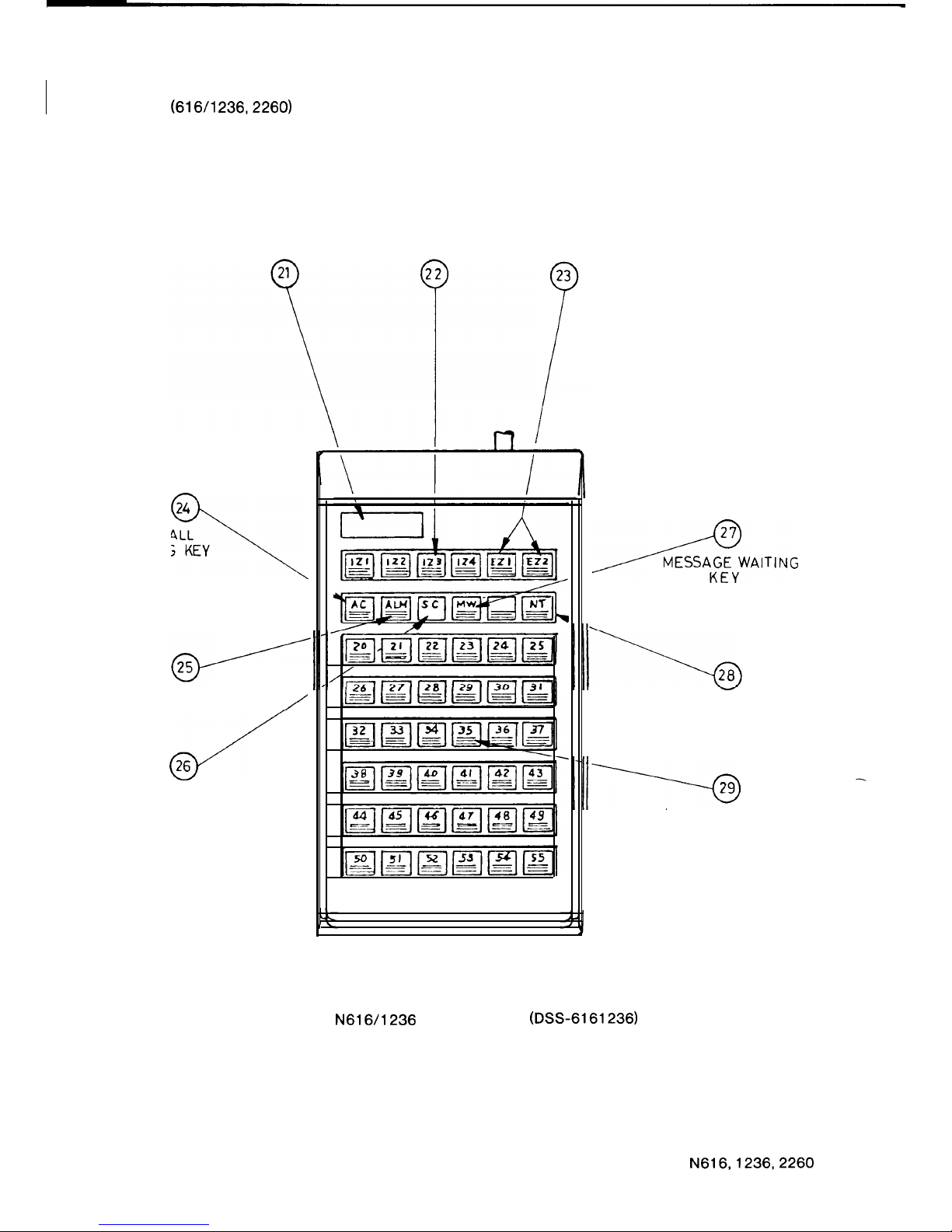
1.3.5
DSS CONSOLE NOMENCLATURE
(616/l 236,226O)
4 DIGIT
INTERNAL ZONE
EXTERNAL ZONE
DISPLAY
PAGING KEYS
PAGING KEYS
24
ALL CALL
3
PAGING KEY
ALARM LED
/
4
26
SIGNAL CALL KEY
AWAITING
NIGHT TRANSFER
KEY
DIRECT STATION
SELECTION KEYS
FIGURE 5
N616/1236
DSS CONSOLE
(DSS-6161236)
20
N616,1236,2260
ISSUE 1
Page 24
I
-
L
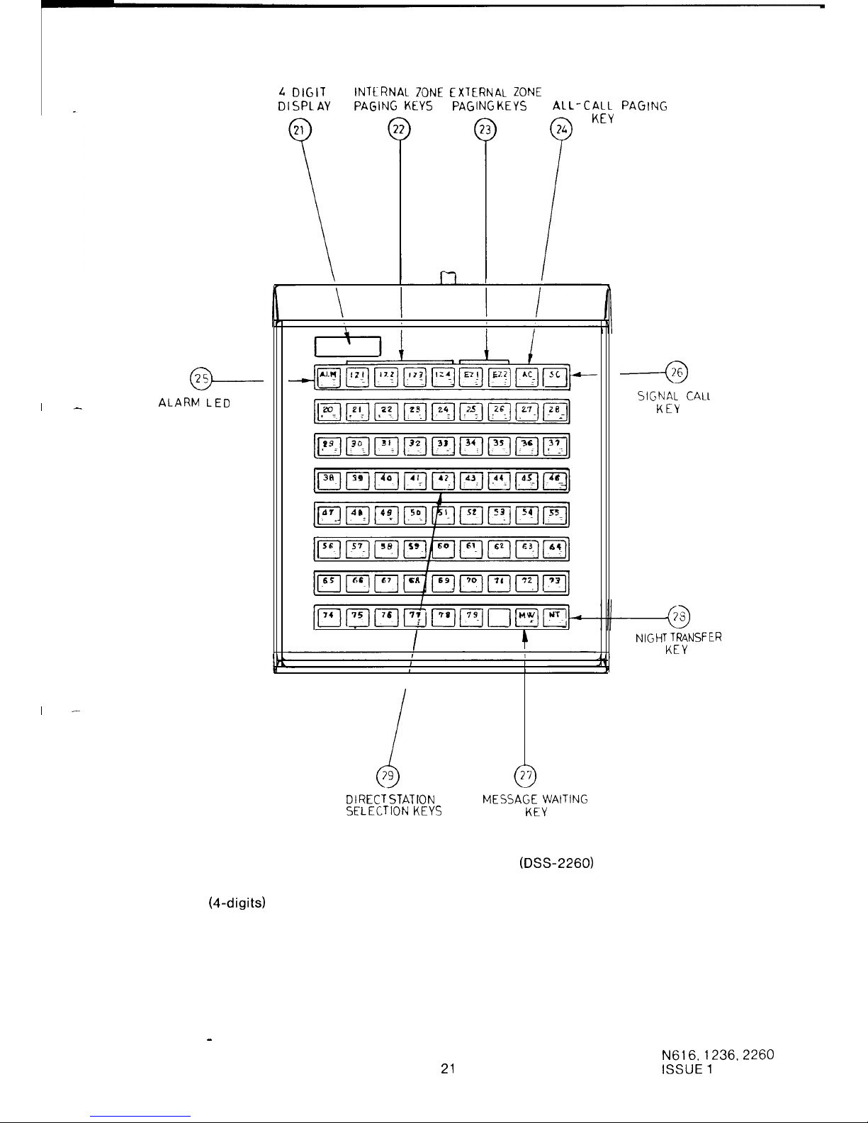
DIGIT INTtRNAl ZONE EXTERNAL ZONE
DISPLAY
PAGING
KEYS PAGING
KEYS
AL
L-CALL
PAGING
KEY
@-
ALARM LED
I
-
DIRECT
STATION
MESSAGE
WAITING
SELECTION
KEYS
KEY
FIGURE 6 N2260 DSS CONSOLE (DSS-2260)
21.
Display
(4-digits)
22.
Internal Zone Paging Keys
23.
External Zone Paging Keys
24.
All Call Paging Key
25.
Alarm Lamp
26.
Signal Call Key
27.
Message Waiting Key
28.
Night Transfer Key
29.
Direct Station Selection Keys including Busy Lamp Field
----a
SIGNAL CALL
KEY
NIGHT TRANSFER
KEY
DSS Station - the station located beside the DSS Console.
21
N616,1236.2260
ISSUE 1
Page 25
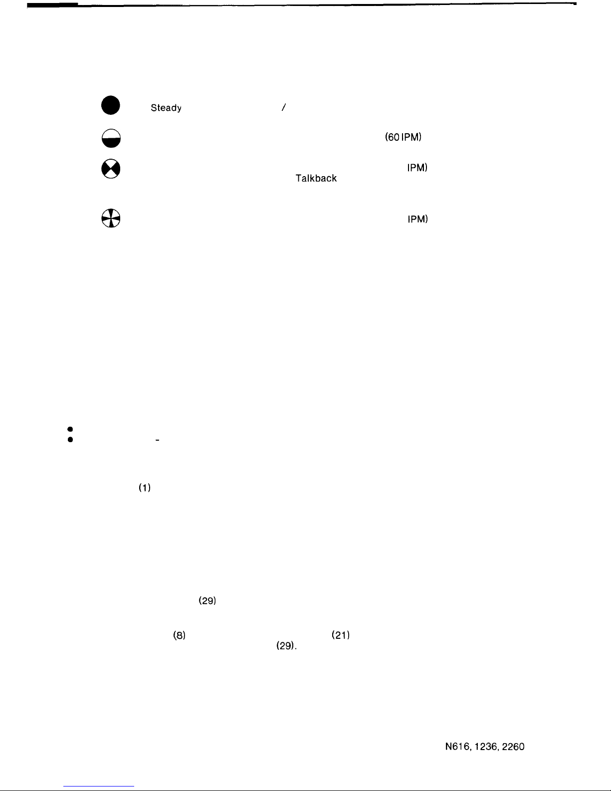
1.3.6
DSS CONSOLE LED INDICATIONS
The Busy Lamp Field shows station status
Off Hook / Busy Condition
0
Slow Flash
Message Waiting
Battery Low
(60
IPM)
8
Flash
Station receiving a
(120
IPM)
Handsfree
Talkback
Intercom
Call
Rapid Flash
Do Not Disturb
Alarm
(300
IPM)
1.3.7
DSS CONSOLE OPERATIONS
SUMMARY
DSS Cal I
Automatic Exchange Line Hold
Digits Display
DSS Override
Signal Call
Automatic Ring Back
Message Waiting
Night Transfer
Alarm Indication
Battery Low Condition
DSS CALL
A DSS Call may be one of the following;
a
Intercom Call
0
Paging Call
-
All Call Paging
Internal Zone Paging
External Zone Paging.
To make a DSS Call.
Lift the Handset
(1)
at the DSS Station.
Press the single function key (22, 23, 24, 29) corresponding to the type and destination of the
call you wish to make.
Automatically the Intercom or Paging Call will be established.
NOTE:
A DSS Console cannot take part or set-up a conference using the ADD ON facility. A
conference must be set-up from the DSS station, only.
AUTOMATIC EXCHANGE LINE HOLD:
When the attendant at a DSS Console answers an exchange line call, the call may be
transferred using a DSS Key
(29)
or by initiating a paging call using the DSS Console’s special
function keys (22, 23, 24).
This action automatically places the exchange line on hold. Therefore, it is not necessary to
operate the HOLD Key
(8)
at the DSS Station. The Display
(21)
will show the call is held by the
station corresponding to the operated DSS Key (29).
DIGITS DISPLAY:
The two digits on the left side of the display show the number of the held exchange lines and the
two digits on the right side of the display shows the number of the station which holds the
exchange line.
22
N616,1236,2260
ISSUE 1
Page 26
DSS OVERRIDE:
Calls from the DSS Console have priority over Intercom Calls and Paging Calls.
When the DSS Console overrides a call, the originator of the call will hear DSS Intrusion Tone. A
flashing LED in the DSS Key
(29)
indicates that a call may be overriden.
DSS Console priority over Do Not Disturb is a programmable option.
NOTE
A DSS Console can not override a remote or internal extension which is on Do
Not
Disturb.
SIGNAL CALL:
When a DSS Console attendant does not receive a response after transferring an exchange line
call using a DSS Key
(29)
the SC Key
(26)
may be used.
Operation of the SC Key (26), after a DSS Key
(29)
has been depressed, will cause Audible
Signalling to be transmitted through the Station Speaker at the station to which the call has
been transferred.
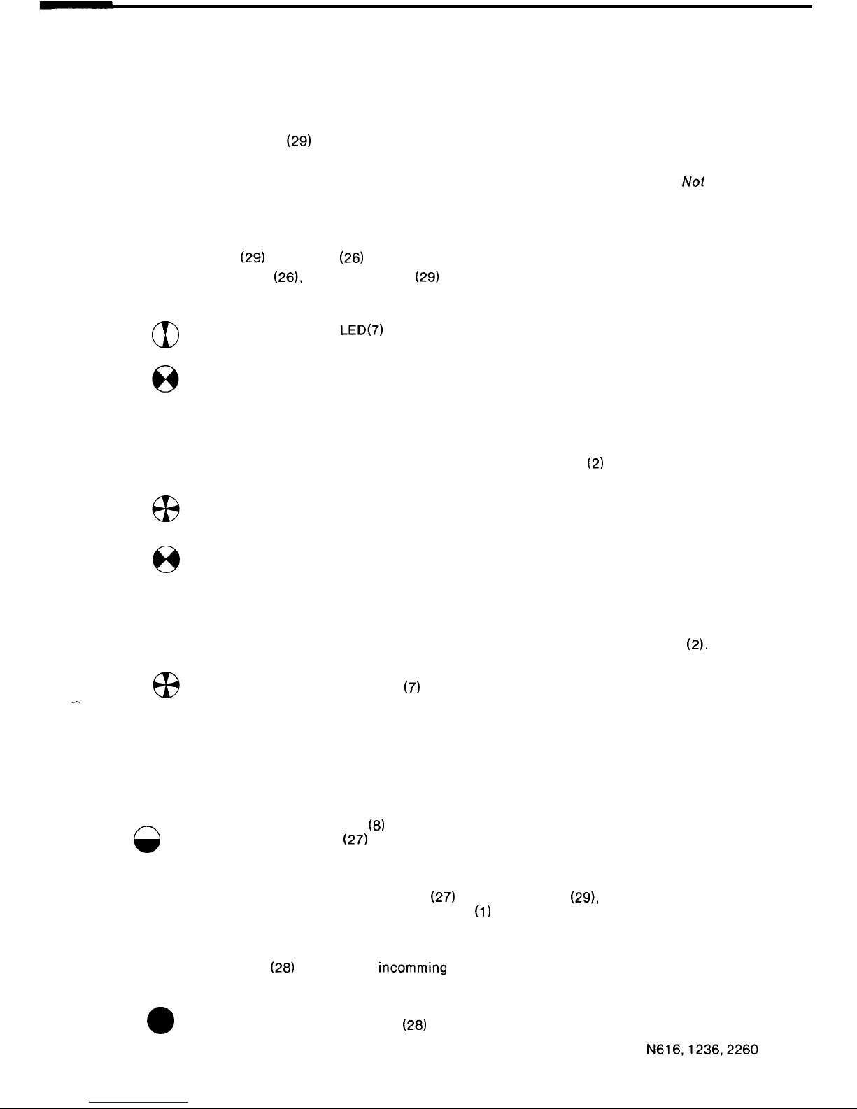
aI
The Exchange Line LED(7) will indicate Exclusive Hold at the station to
which the call has been transferred.
And Hold at all other stations.
Audible Signalling will be transmitted to the station for 20 seconds.
If the call is not answered within 20 seconds it will be directed back to the DSS Console.
Audible Signalling will be transmitted from the DSS Station Speaker
(2)
until the call is
re-answered.
The Exchange Line Status LED (7) will indicate I-Hold condition at the DSS
station, and the station to which the call has been transferred.
8
And hold condition at all other stations.
AUTOMATIC RING BACK:
If exchange line calls transferred from the DSS Console are not re-answered within the
preprogrammed ring back time, Audible Signalling will be heard via the DSS Station Speaker
(2).
-.
The Exchange Line Status LED
(7)
will indicate the I-HOLD condition.
MESSAGE WAITING:
To indicate to a station that there is a message at the DSS Console, carry out the following
procedure.
After pressing the desired DSS Key (29).
Press the MW Key (27).
8
The Message Waiting LED
(8)
(Hold LED) at the unattended Station and the
corresponding DSS LED
(27)
on the DSS Console will indicate Message Waiting
active.
The Message Waiting condition will clear when there is a call from the associated station or if
the DSS Console attendant operates the MW Key
(27)
and the DSS Key (29), corresponding to
the station where the message was left, while the Handset
(1)
is on-hook.
NIGHT TRANSFER:
Operation of the NT Key
(28)
will direct all
incomming
audible signals to the programmed Night
Transfer Station.
a
The Night Transfer Status LED
(28)
will indicate active.
N616,1236,2260
23
ISSUE 2
Page 27
ALARM INDICATION:
When the external alarm signal is detected (option), Alarm Tone will be heard at the DSS Station.
G3
The Alarm Status LED
(25)
will indicate an Alarm.
The condition is stopped when the alarm signal is cleared.
BATTERY LOW CONDITION:
8
The Alarm Status LED
(25)
indicates the Battery Low Condition.
If the battery is not replaced in a short time the system will
malfunction.
1.3.6
OPTIONAL EQUIPMENT
-
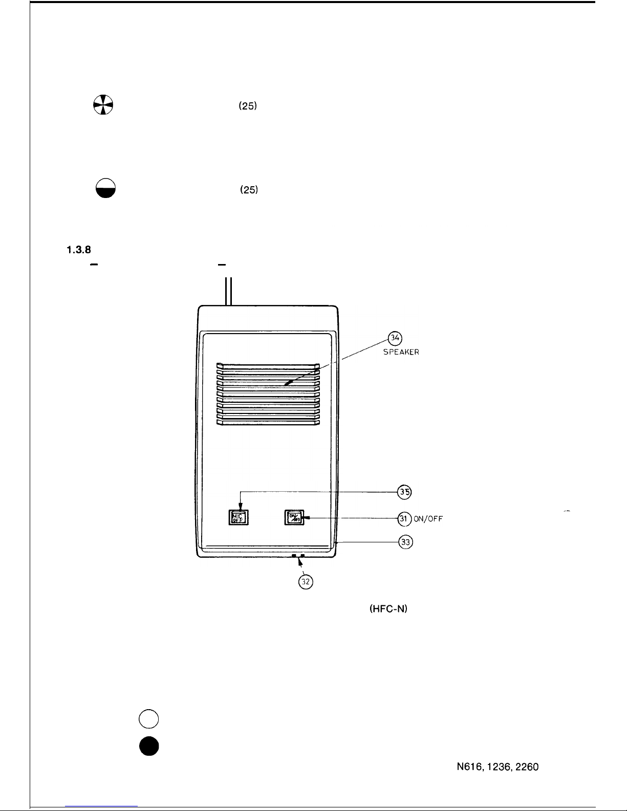
HANDSFREE CONSOLE
-
MICROPHONE
CUT- OFF KEY
--ON/OFF
KEY
0
33
VOLUME CONTROL
0
32
MICROPHONE
FIGURE 7 HANDSFREE CONSOLE (HFC-N)
Nomenclature
31. On/Off Key and LED
32. Microphone
33. Volume Control
34. Speaker
35. Microphone Off Key and LED
Lamp Indications
0
Off Non-operational State
On
Active Handsfree Condition
Microphone Off Condition
24
N616,1236,2260
ISSUE 2
Page 28
Operation
.
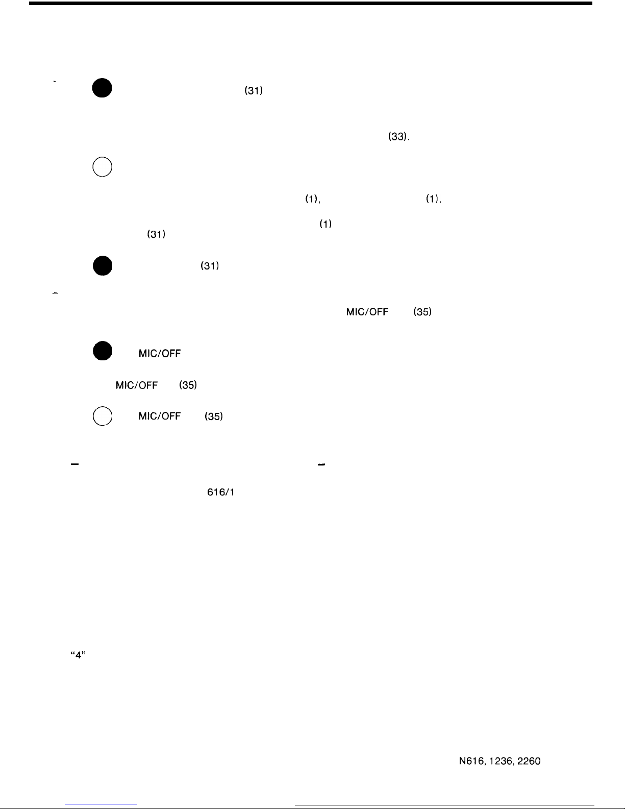
Press the ON/OFF Key
(31)
to activate the Handsfree condition.
Select the required system feature using appropriate station key.
If necessary adjust the speaker volume level using the Volume Control (33).
0
Press the ON/OFF Key (31) again to terminate the call.
To transfer the conversation to the station Handset
(11,
simply lift the Handset
(1).
The ON/OFF
LED (31) will go off automatically.
To transfer the conversation from the station Handset
(1)
to the Handsfree Console, first press
the ON/OFF Key
(31)
and the
0
ON/OFF LED
(31)
will come on.
-
Now, place the Handset (1) on-hook.
To prevent your speech being transmitted, press the
MIC/OFF
Key
(35)
to turn off the
microphone, the
0
MIC/OFF
LED (35) will come on.
Press the
MIC/OFF
Key
(35)
again, to turn the microphone on. The
0
MICYOFF
LED
(35)
will go off
-
INTERNAL EXTENSIONS (INTERNAL STATIONS)
-
Nomenclature
Key Stations:
616/l
23612260 stations shown in the front of the instructions
(fig. 1, 2 8 3).
Internal Extensions:
Telecom Touchfone 10 or rotary dial telephones with decadic
dialling.
Internal Extensions are normally located in the same premises as the system and are restricted
in their use of system facilities.
For Internal Extensions with intercom access only, refer to the operating instructions for
Remote Extensions.
+ EXCHANGE LINE CALLS
Placing an Exchange Line Call :
Lift the Handset. Wait for Internal Dial Tone.
Dial “3” to allocate any free Exchange Line for your call or,
“4”
to allocate a free Exchange Line from the second group when the exchange lines are
grouped.
Dial the desired number after the Exchange Line Dial Tone has been connected.
N616,1236,2260
25
ISSUE 2
Page 29

Answering an Exchange Line Call :
There is no facility to directly answer an Exchange Line Call. Exchange line calls must be
transferred to an Internal Extension using the ADD ON Conference facility at a Key Station, or by
a signal call from a DSS Console.
Transferring an Exchange Line Call :
An Exchange Line Call transferred to an Internal Extension can be transferred to a Key Station
or Internal Extensions as follows:
Depress the Switchhook momentarily while talking on an Exchange Line Call. This operation
will put the Exchange Line on Add On Standby. The Exchange Line Key
(7)
on Key Stations will
indicate Busy.
Wait for
Internal
Dial Tone. If dial tone is not received, depress the Switchhook again and the
Exchange Line is returned to you. Repeat the above operation if necessary.
Dial the Station to which the Exchange Line is to be transferred using an Intercom Call.
Ensure that the person being called answers using the Handset.
Depress the Switchhook again and a conference is set-up between three parties. Place your
Handset on-hook and the connection between the two remaining parties is maintained.
+ INTERCOM CALLS
Placing an Intercom Call :
Lift the Handset. Listen for Internal Dial Tone.
Then dial
“2”
and the number of the required Key Station or Internal Extension.
If the call is for another Internal Extension, Ring Tone or Busy Tone is heard in the receiver. Wait
for the called party to answer.
If the call is for a Key Station, and the station is not busy, Single or Double Tone Burst is heard
and a normal “Handsfree Talkback” call is initiated.
Answering an Intercom Call :
Incoming calls are announced when the telephone rings.
Lift the Handset to answer.
Three-party Intercom Conference
A three-party intercom conference may be set-up as described for transferring an exchange
line call, above.
+ PAGING
Lift the Handset.
Wait for Internal Dial Tone.
Dial the desired paging number for
All Call Paging
80
Internal Zone Paging
81 -84
External Zone Paging
85 or 88’
*
86 is not provided in the 616 system.
+ CALL TO A DSS CONSOLE ATTENDANT
Lift the Handset.
Wait for Internal Dial Tone.
Dial
“0”
for the first DSS Console or
“9” for the second DSS Console.
26
N616,1236,2260
ISSUE 2
Page 30
-
REMOTE EXTENSIONS (REMOTE STATIONS)
-
/
POWER ON
LAMP
POWER SUP PLY
MAINS
FUSES
FUSE
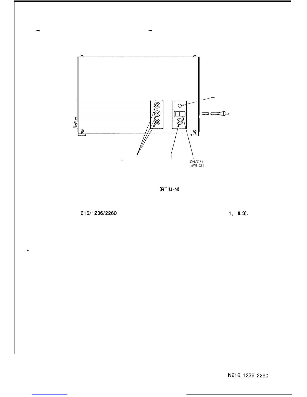
FIGURE 8 REMOTE EXTENSION AND TIE LINE
INTERFACE UNIT (RTIU-N)
Nomenclature
Key Stations:
616/l 236/2260
stations shown in the front of the instructions (fig. 1, 2 8.3).
Remote Extension:
Telecom Touchfone 10 or rotary dial telephones with decadic dialling.
Remote Extensions are located in premises remote from the system and are restricted in their
use of system facilities.
+ EXCHANGE LINE CALLS
-
Placing an Exchange Line Call :
Call a Key Station.
Ask that person to connect an exchange line to your telephone using the ADD ON Conference
facility.
Dial the desired number after Exchange Line Dial Tone has been connected.
Answering an Exchange Line Call :
There is no facility to directly answer an Exchange Line Call. Exchange line calls must be
transferred to a Remote Extension using the ADD ON Conference facility at a Key Station.
Transferring an Exchange Line Call :
An Exchange Line Call transferred to a Remote Extension can be transferred to a Key Station,
Internal Extension or Remote Extension as follows:
Depress the Switchhook momentarily while talking on an Exchange Line Call. This operation
will put the Exchange Line on Add On Standby.
N616,1236,2260
27 ISSUE 2
Page 31
Wait for Internal Dial Tone. If dial tone is not received, depress the Switchhook again and the
Exchange Line is returned to you. Repeat the above operation if necessary.
-
Dial the Station to which the exchange line is to be transferred using an Intercom Call.
Ensure that the person being called answers using the Handset.
Depress the Switchhook again and a conference is set-up between three parties. Place your
Handset on-hook and the connection between the two remaining parties is maintained.
+ INTERCOM CALLS
Placing an Intercom Call :
Lift the Handset. Listen for Internal Dial Tone.
Then dial the number of the required Key Station or Remote Extension.
If the call is for another Remote Extension or Internal Extension, Ring Tone or Busy Tone is
heard in the receiver. Wait for the called party to answer.
If the call is for a Key Station, and the station is not busy, Single or Double Tone Burst is heard
and a normal “Handsfree Talkback” call is initiated.
Answering an Intercom Call :
Incoming calls are announced when the telephone rings.
Lift the Handset to answer.
Three-party Intercom Conference :
A three-party intercom conference may be set-up as described for transferring an exchange
line call, above.
-
TIE LINES
-
When a system uses a tie line the tie line takes the place of an exchange line. Therefore, a tie
line appears as an exchange line key on each station.
OUTGOING CALLS
Lift the Handset.
Select the exchange line key corresponding to the Tie Line.
The calling party will hear ring tone until the call is accepted.
INCOMING CALL
Incoming calls on a Tie Line are handled in the same way as an exchange line incoming call.
1.3.9
QUICK REFERENCE TABLE
STATIONS
PAGING: 80
81 -84
85 - 86
MEET-ME ANSWER PAGING:
MESSAGE WAITING:
SIGNAL CALL:
ALTERNATE POINT ANSWERING:
DSS ATTENDANT:
INTERNAL EXTENSIONS
Outgoing Exchange Line Calls:
Intercom Calls:
Paging:
DSS Attendant:
Hold / Transfer:
All Call
Internal Zones
External Zones
Originator - Page then
‘*’
Respondent - Off-hook “8”
Off-hook, ICM,
“1”.
Any extra digit.
Off-hook, Called station number.
Off-hook, ICM,
“0” (1
st) or “9” (2nd).
“3” or “4”
“2” then intercom number.
“80” All Call, “81 - 84” Internal Zone,
“85 - 86” External Zone.
“0” or “9”
Switchhook Depression (Add on).
28
N616,1236,2260
ISSUE 2
t
Page 32
1.4 SYSTEMS CAPACITIES AND COMPONENTS
1.4.1 SYSTEMS CAPACITIES
The maximum capacities of each system are tabulated below:
-
616
1236 2260
Common Exchange Lines
(1) 6
12 22
Exclusive Exchange Lines
(2)
4 4
6
and/or Hot Lines
Total Exchange Lines
8
14
26
Intercom Links
4
Stations
16
3%3,
6:(3)
DSS Consoles
2(4)
2 2
Notes:
(1)
The last two exchange lines on all systems can be converted to exclusive
exchange lines or hot lines. NB: circuits I& 2 on ELNB-A/4 are not used.
(2) This figure assumes that the last two exchange lines are converted from
common exchange lines to exclusive exchange lines or hot lines.
The total number of exclusive exchange lines and hot lines cannot exceed this
number.
(3)
A DSS console uses one station port. Therefore, the total number of stations and
DSS consoles is 36 in the 1236 and 60 with the 2260.
(4)
The 616 provides an extra DSS console port on the EDTB-B card. Therefore, the
total number of DSS consoles and stations is actually 17.
Refer to the Appendix for further information.
Call Metering Unit
The unit contains three metering circuits with digital displays. Any number of units may be used
to cater for the exchange lines connected to the system.
Remote Extension and Tie Line Interface Unit
(RTIU)
The unit has a capacity to provide two interface circuits for any combination of remote
extensions, ring-in/ring-out tie lines or loop-in/ring-out tie lines. The number of RTIU’s which
can be used depends on system size. In the case of tie line interfaces, any number up to the
maximum number of exchange lines can be used. In the case of remote extensions, any number
up to the maximum number of stations can be used.
SYSTEM LIMITS
ITEM
MAX. LOOP LIMITS
TS-616
TS - 1236
TS - 2260
DSS - 616 1236
DSS - 2260
IXT
RXT
MUSIC SOURCE
INPUT IMPEDANCE
INPUT LEVEL
EXTERNAL AMPLIFIER
OUTPUT LEVEL
RELAY CONTACTS
ALARM INPUT
SENSING TYPE
SPECIFICATION
84 ohms* (490m
0.5mm
cable)
74 ohms* (430m 0.5mm cable)
64 ohms* (370m 0.5mm cable)
52 ohms (300m
0.5mm
cable)
48 ohms (280m 0.5mm cable)
700 ohms
(4km
0.5mm cable)
1500 ohms (8.7km
0.5mm
cable)
600 ohms
0.05 - 0.3V RMS
2W into an 8: ohm load
616 1 circuit; 1236, 2260 2 circuits
1.25A at 24V dc
Either N/O or N/C Dry contacts.
*;hese
figures must be reduced by 10 ohms if a handsfree console is
attached to a station.
N616,1236,2260
29 ISSUE 2
Page 33
1.4.2 SYSTEM COMPONENTS
1.4.2.1 Components
The systems are made-up of the following items; main equipment (ME), power supply (PSI,
stations, DSS console and powerfail bell. In addition, the following items are available;
handsfree console
(HFC),
call metering unit (CMU), ring generator unit
(RGU)
and the
remote extension and tie line interface unit
(RTIU).
(i)
Main Equipment
The main equipment is a one, two or three shelf rack depending on system size. The 616
system has the main equipment and power supply integrated into one unit. The main
equipment has connectors located on the side of the ME which provide all necessary
connections for power supplies and installation wiring. The main equipment houses
polarised plug-in printed circuit boards. Refer to table 1 for details of printed circuit boards
housed in the main equipment. Figures 15, 16 & 17 show the construction of the main
equipment and location of PBA’s.
30
N616,1236,2260
ISSUE 2
Page 34
DC
I
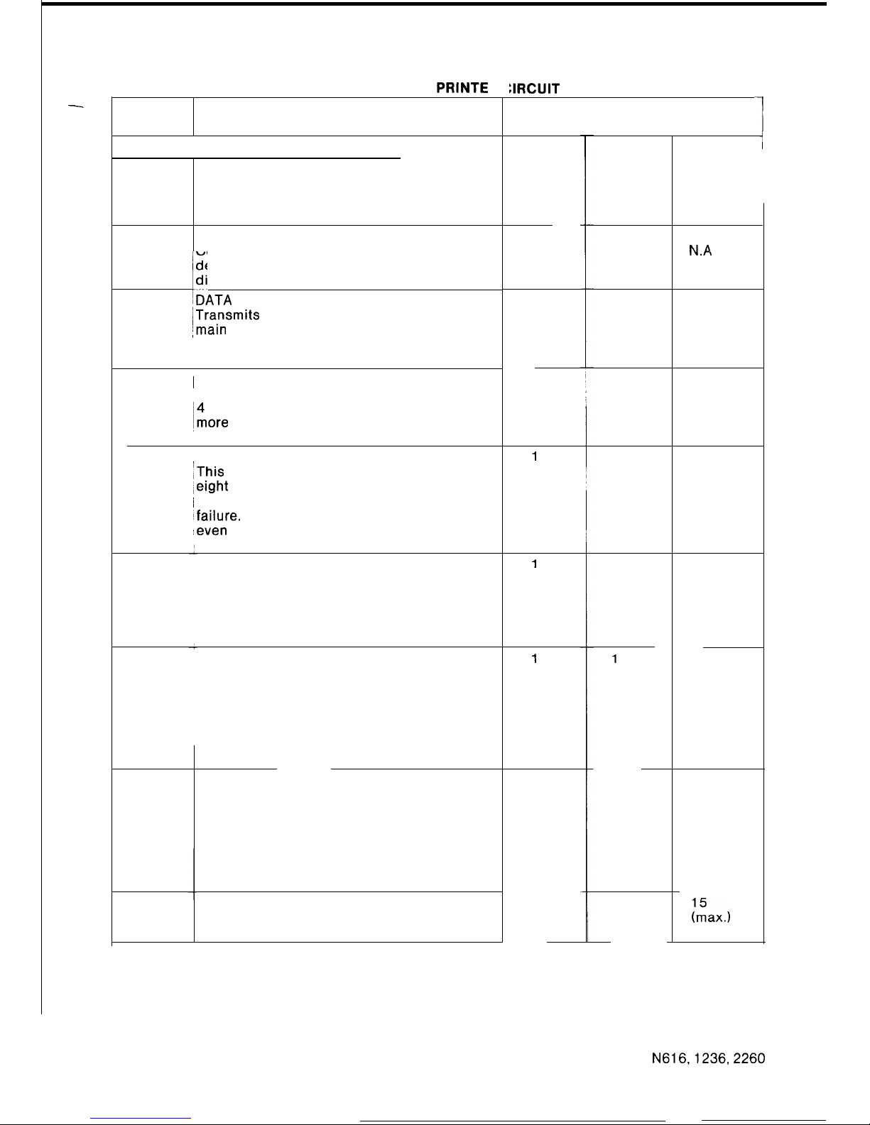
TABLE 1: MAIN EQUIPMENT PRINTE
BOARD
BOARD
CODE
DESCRIPTION
STANDARD BOARDS (MUST BE EQUIPPED)
ECPB-A
CENTRALPROCESSORBOARD
This board has the main CPU and
ROM containing the operational
programme.
ECMB-A
CENTRAL MEMORY BOARD
ECMB-B
Contains memory for site
ECMB-D
dependent data and abbrievated
I...~
dial numbers.
EDTB-A
IDATA TRANSMISSION BOARD
ITransmits
key data between the
jmain equipment and stations.
‘On the EDTB-B (N616 only) a DSS
EDTB-B
port is provided.
EICB-A
1 INTERCOM CONTROL BOARD
Controls voice switching for up to
i4
Intercom links. If there are
~more
than 4 links required an
expansion board must be used.
EPFB-A
‘POWERFAIL BOARD
iThis
board transfers a maximum of
,eight
exchange lines to predetermined
~ stations when there is a power
Ifailure.
This board must be equipped
,even if no powerfail stations are
:IRCUIT BOARDS
MAXIMUM QUANTITY PER SYSTEM
1
-
N1236 N2260
N616
1
i
1
1
N.A.
1
N.A.
1
N.A
N.A
N.A.
N.A.
1
N.A.
1
1
N.A.
1
N.A
1
1
1
1
2
4
used.
TONE AND SENDER BOARD (VF)
This board contains tone generators
for internal tones and audible
signalling. This board also provides
VF signalling for all exchange lines
up to the maximum system size.
TONE AND SENDER BOARD (DECADIC)
This board contains tone generators
for internal tones and audible
signalling and a microprocessor which
controls decadic signalling on exchange
lines. This unit controls decadic
signalling for up to 16 exchange
lines.
TONE AND SENDER EXPANSION
BOARD (DECADIC)
Contains a microprocessor which
controls decadic signalling on exchange
lines. This board is used to control
decadic signalling on an additional ten
exchange lines and must be used with the
ETSB-B board.
STATION INTERFACE BOARD
This board provided interfaces
for four stations
ETSB-A
1 1
1
ETSB-B
1
1
ETSB-C
N.A.
N.A.
1
4
(max.)
9
(max.)
7rZax.)
ESTB-C
N616,1236,2260
31
ISSUE 2
Page 35
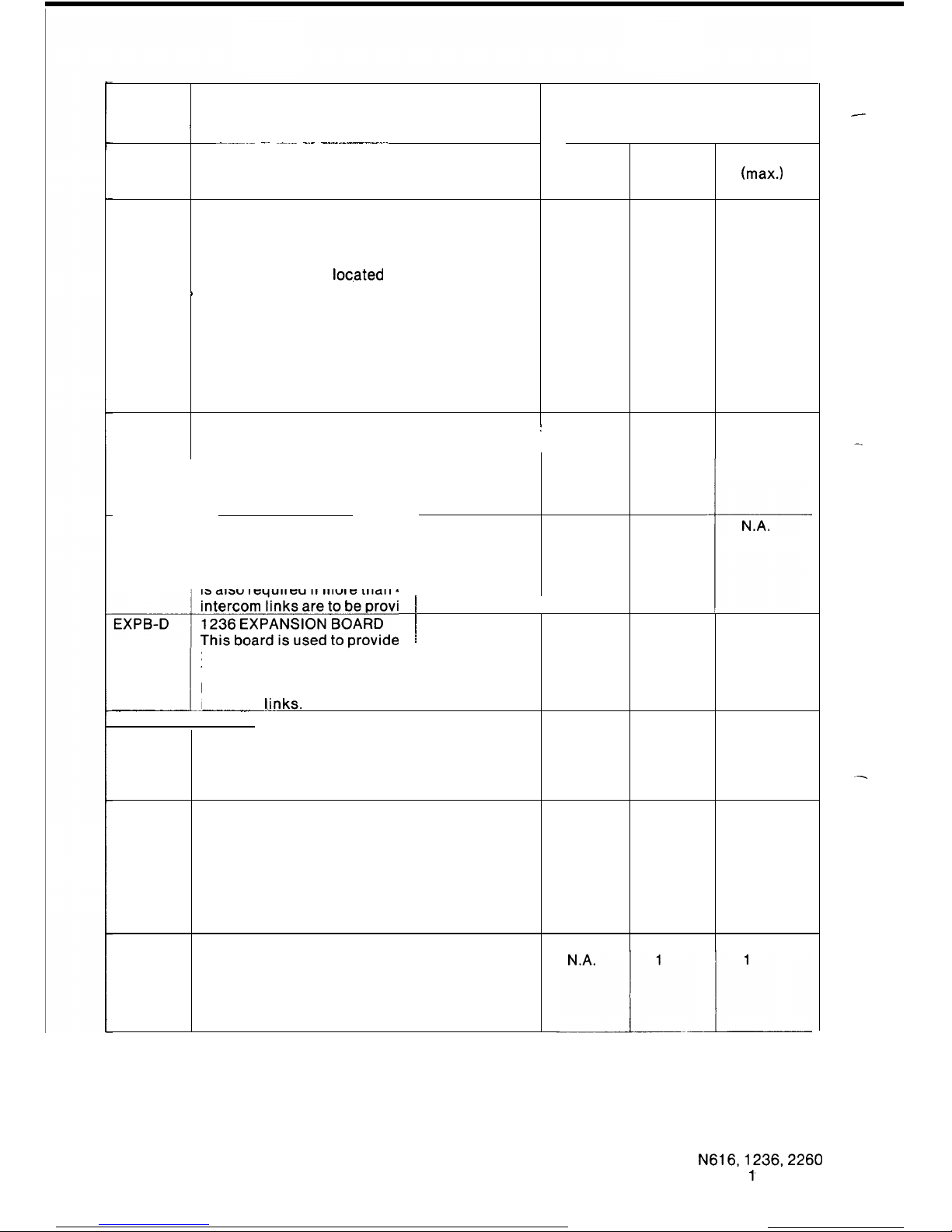
BOARD BOARD
MAXIMUM QUANTITY PER SYSTEM
CODE
/
DESCRIPTION
N616 N1236
N2260
---.- -~ ~-.- -.- -.-----.---.~.
ELNB-A EXCHANGE LINE BOARD
2
4
7
This board contains four exchange (max.) (max.) (max.)
line circuits.
EXPB-A 2260 EXPANSION BOARD
N.A. N.A.
2
This board provides an
expansion when more than 12
exchange lines are equipped on a
2260. The board is
loc,ated
in position
B
EXPB-Al . If more than 18 exchange
lines are equipped on a 2260 a
second EXPB-A board is required and
it is located in position EXPB-A2.
An EXPB-A board is required if more
than 4 intercom links are to be
provided. The board is located in
position EXPB-Al.
EXPB-B
2260 EXPANSION BOARD
:
N.A.
N.A.
1
This board is used to provide
2 extra voice switching circuits.
This board must be used with an
EXPB-A to provide the 2 extra
intercom links.
-I---
EXPB-C 1236 EXPANSION BOARD
N.A.
1
N.A.
This board provides an expansion
when more than 12 exchange lines
are equipped on a 1236. This board
is also required if more than 4
intercom links are to be provided.
t
‘“‘““~;4;“.10NONO;~~de
~ N.A. 1 N.A.
2
extra voice switching circuits.
This board must be used with an
I
EXPB-C to provide the 2 extra
intercom
tinks.
~__
--__~-.~
OPTIONAL BOARDS
EPGB-B
PAGING BOARD
This board contains two audio
N.A.
1
1
amplifiers to provide the external
paging facility.
EGPB-A GROUNDING/PAGING BOARD
This board contains one audio
1
N.A.
N.A.
amplifier to provide an external paging
facility. This board is also used
to provide the Earth Recall facility,
which is used for hold, transfer, and
enquiry facility when the systems are
connected to a PABX.
EGDB-A GROUND RECALL BOARD
This board is used to provide
the Earth Recall facility which
is used to provide hold, transfer,
and enquiry facility when the systems
are connected to a PABX.
-
N616,1236,2260
32
ISSUE
1’
Page 36
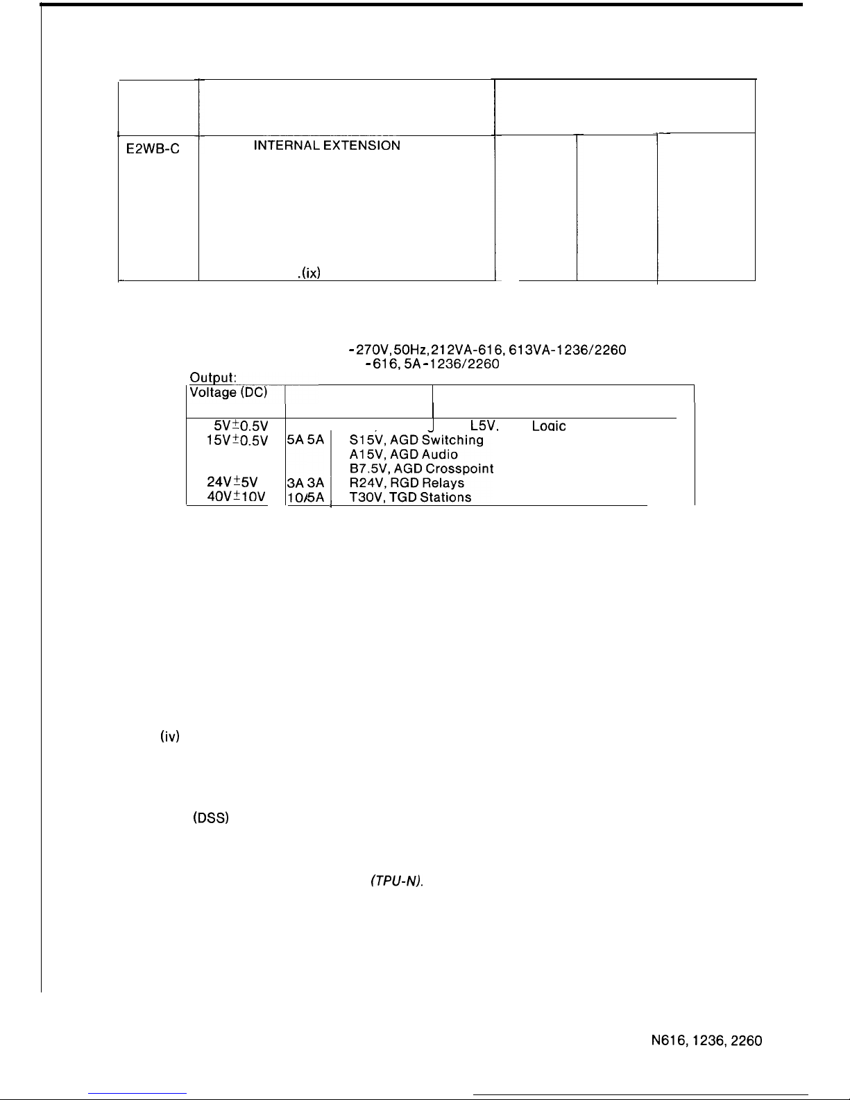
BOARD
CODE
E2WB-C
-
(ii)
(iii)
(iv)
BOARD
DESCRIPTION
2-WIRE
lNT==XFgti
BOARD
This board is used in place
of an ESTB-C board. It provides
interfaces between four 2-wire
telephones and the system. It is
recommended that at least one ESTB-C
board is used per system to allow
the use of a DSS Console.
A RGU is required, refer to
Section 1.4.2.1 .(ix)
MAXIMUM QUANTITY PER SYSTEM
N616
N1236
3
8
N2260
-
14
Power Supply
The 616 power supply is integrated into the main equipment rack. The 1236 and 2260 use
a common power supply. The ratings of the power supplies are as follows.
Input Voltage (AC): 225V -
27OV,
50Hz,
212VA-616,613VA-1236/2260
Maximum Input Current: 2A -
616,5A - 1236/2260
*
Current Designation
5VkO.5V
15vio.5v
616
123612260
1
3A 3A L5V. LGD
Loaic
24V’5V
40v*10v
;;A 1 ?!&,!!$!$~~nt
Bias
3
A cable with polarised connectors provides the connection between the power supplies
and the main equipment. Power-on lamps, switches and fuses are located on the front of
the power supply. Figures 18 shows an external view of the power supply.
Stations
There are two types of stations; standard stations and powerfail stations.
Standard stations contain a telephone network including handset, a dial key pad,
non-locking function keys, status lamps, a microphone, a speaker, a volume control and
electronics to control the stations operation.
Powerfail stations, in addition to the above, contain a powerfail dial either decadic or DTMF
and an electronic buzzer to signal incoming calls during power failure. One powerfail
station maybe equipped for each exchange line connected to the system.
Figures 19, 20, 21 show the stations.
DSS Console (Fig. 22, 23)
Primarily the DSS Console provides facilities required for an operators position. That is, a
simpler means of answering and transferring calls, and a display of the status of each
station in the system.
The DSS Console consists of a series of single function keys and direct station selection
(DSS)
keys with corresponding status lamps, a speaker for audible signalling, and a 4 digit
display to show held exchange lines and the station holding the exchange line.
NOTE:
As systems are programmed using a special DSS console, a DSS console
socket must always be wired. The modified console is known as a Test and
Programming Unit
(TPU-N).
N616,1236,2260
33 ISSUE 2
Page 37
(4
Powerfail Bell
A powerfail bell may be connected to the systems to provide incoming audible signalling
when a power failure occurs.
When the power fails the powerfail bell will be connected in parallel with the powerfail
station.
The powerfail bell consists of a capacitor, a bell and a lamp that flashes with the incoming
ring (fig. 25).
(vi)
Handsfree Console
A handsfree console
(HFC)
may be connected to a station to provide full handsfree
capability for all types of calls (fig. 24).
(vii)
Call Metering Unit
The call metering unit may be connected to exchange lines to provide an indication of the
cost of calls. The call metering unit records meter pulses sent from the local exchange (fig.
26).
(viii)
Remote Extension and Tie Line Interface Unit
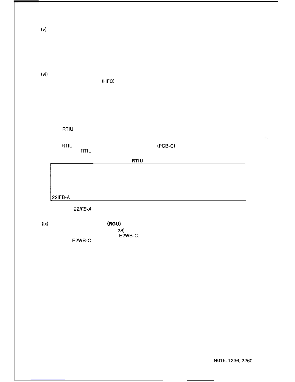
The
RTIU
is a small sub rack which provides the possibility to interface with remote
extensions or tie lines with a maximum capacity of two interfaces per sub rack and a
standard card.
The
RTIU
is equipped with its own power supply (PCB-C). The components which can be
used with the
RTIU
are shown in Table 2 (fig. 27).
(ix)
Ring Generator Unit (RGU)
The ring generator unit (figure
28)
generates ring voltage for Internal Extensions. The RGU
is used in conjunction with the E2WB-C. The RGU is capable of providing ring voltage for
up to two E2WB-C boards.
1.4.2.2
Customer Provided Optional Equipment
Standard
RTB-A
Options
RRB-A
LRB-A
RXB-A
22lFB-A
Table 2 : RTIU BOARDS
Ring and Tone Source
Ring-in, Ring-out Tie Line Interface
Loop-in, Ring-out Tie Line Interface
Remote Extension Interface
616.1236. 2260 Interface Circuit for RXB-A
Note:
For a remote extension a pair of cards are required, the RXB-A card and the
221FB-A
card which is a main equipment interface card. For each remote
extension both cards must be provided.
Loudspeakers or a public address system with 8 ohm input impedance for external zone paging
options.
A music source for background music and hold music.
An alarm detector or supervisory system for alarm signalling
N616,1236,2260
34
ISSUE 1
Page 38
1.4.3
BLOCK DIAGRAM DESCRIPTION
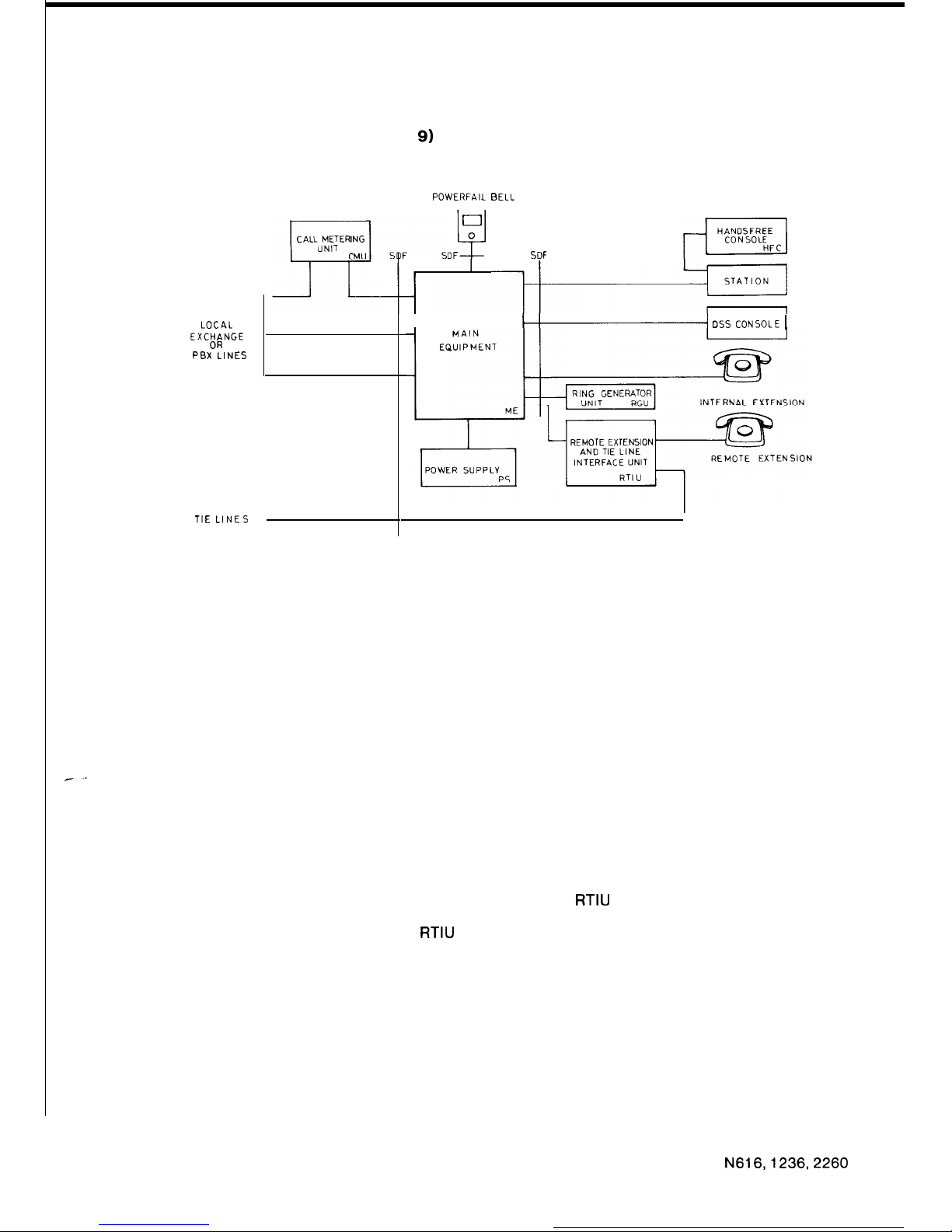
1.4.3.1 System Block Diagram (Figure
9)
This shows the main items of the system and their interconnection.
POWERFAIL BELL
LOCAL
EXCHANGE
OR
PBX LINES
TIE LINES
J
SDF
I
w
DSS CONSOLE 1
FIGURE 9 SYSTEM BLOCK DIAGRAM
Incoming Local Exchange Lines or PBX Lines are connected to the main equipment. A Call
Metering Unit may be used to record meter pulses sent from the local exchange. Tie Lines are
connected via a RTIU.
The Power Supply provides all the power necessary to operate all system modules with the
exception of the RTIU which has its own power supply.
Powerfail Bells, if used, are automatically connected across incoming exchange lines when the
power fails.
Handsfree Consoles are equipped on a per station basis and are directly connected to the
station. They have no direct connection with the M.E.
The following devices may be connected to M.E. ports, Stations, DSS Consoles, Internal
Extensions and Remote Extensions. Standard stations, powerfail stations and the DSS console
are connected to the M.E. by 4 wires, one pair is the speech pair and the other pair is for data
transmission and power feed to the station.
Standard decadic telephones, Internal Extensions, are connected to the M.E. by a single pair of
wires, audio communication and decadic signalling is performed on this pair. A special
interface and Ring Generator Unit is provided so standard telephones can be used.
Remote Extensions are connected to the M.E. via the RTIU. The
RTIU
has a 4 wire connection to
the M.E., (one pair voice, one pair data) and a 2 wire connection to the remote extension for
voice and decadic signalling. Cards in the
RTIU
perform the 4 wire to 2 wire interface.
N616,1236,2260
35
ISSUE 1
Page 39
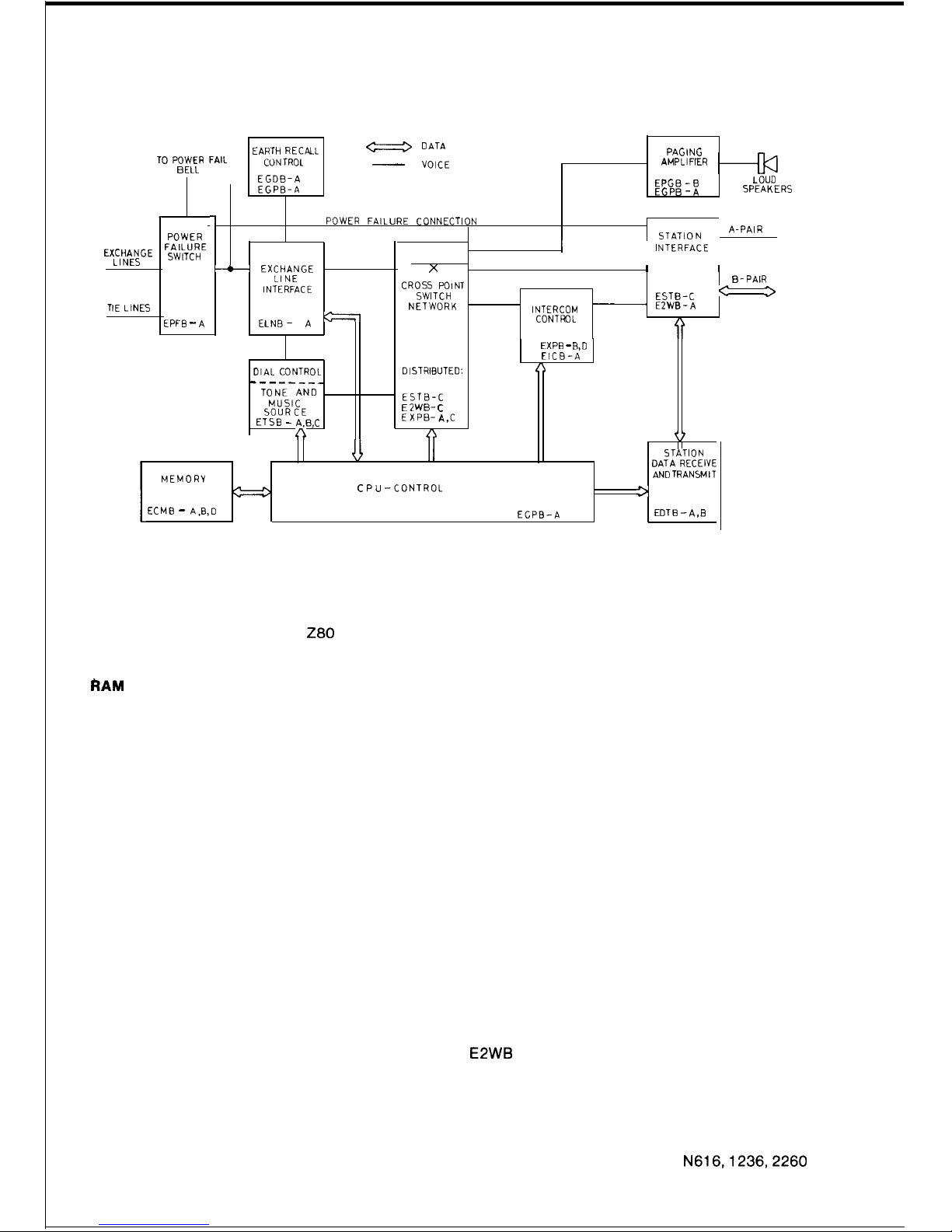
1.4.3.2.
Main Equipment Block Diagram (Figure IO)
EARTH RECALL
a
DATA
TO
POWER FAIL
PAGING
CONTROL
AMPLIFIER
BELL
-
VOICE
EGDB-A
EPGB-B
LOUD
EGPB-A
EGPB-A
SPEAKERS
I
1
POWER FAILURE CONNECTION
STATI ON
A-PAIR
POWER
EXCHANGE
FAILURE
LINES
SWITCH
+
EXCHANGE
LINE
INTERFACE
I
INTERFACE
X
I I
CROSS POINT
SWITCH
NETWORK
B-PAIR
ESTB-C
’
3
INTERCOM
~
EZWB-A
CONTROL
TIE LINES
EPFB -
A
ELNB-
A
=
OIAL CONTROL
-----___
TONE AND
MUSIC
SOURCE
ETSB - A.B,C
n
DISTRIBUTED:
MEMORY
ECMB - A,B,D
- ESTB-C
E 2WB- C
EXPB-A,C
C PU -CONTROL
EXPB - R,D
EICB-A
A
r?
STATION
DATA RECEIVE
AND
TRANSMIT
C
3
ECPB-A
EDTB -A,B
FIGURE 10 MAIN EQUIPMENT BLOCK DIAGRAM
CPU Control consists of the
280
micro-processor, ROM program memory, RAM working
registers, timing and control circuitry. The CPU controls all switching and system data
manipulation.
RAM Memory is used as working memory, to store site dependant data and to store abbreviated
dialling numbers. It is located on the ECMB cards and has a lithium battery to retain the data
when power fails.
Power Failure Switch automatically connects exchange lines directly through to pre-assigned
powerfail stations via the powerfail connection. At the same time the powerfail bell is connected
in parallel with the powerfail station.
Exchange Line Interface provides the d.c. loop termination of the exchange line, ring detect
circuit, audio coupling transformer, dialling relay, line surge protection and distribution for
tones and hold music.
Earth Recall Control is used to apply PBX earth to one wire of the exchange line pair.
Dial Control module in one case, provides the VF tones, and in the other case, provides timing
and control circuits for the loop-disconnect decadic dialling, depending on the type of
exchange lines used.
Tone and Music Source generates all internal system, tones and synthesises hold music, it also
provides the input for background music.
Crosspoint Switch Network is made-up of semiconductor crosspoints and is distributed over a
number of cards. This circuit which decodes the CPU order to operate the crosspoints is
located on the EDTB card. Figure 10 shows how the crosspoint switch matrix is made-up.
Intercom Control controls the voice switching circuits for handsfree talkback.
Station Interface provides circuits for transmission of voice and serial data between the
stations and the M.E. There is no B pair when using the E2WB card.
Station Data Receive and Transmit contains microprocessors which control the transmission
of new status information from the main CPU and receive data of operations initiated at each
station.
Paging Amplifier amplifies the systems audio signals for broadcasting through external
loudspeakers.
N616,1236,2260
36
ISSUE 1’
Page 40
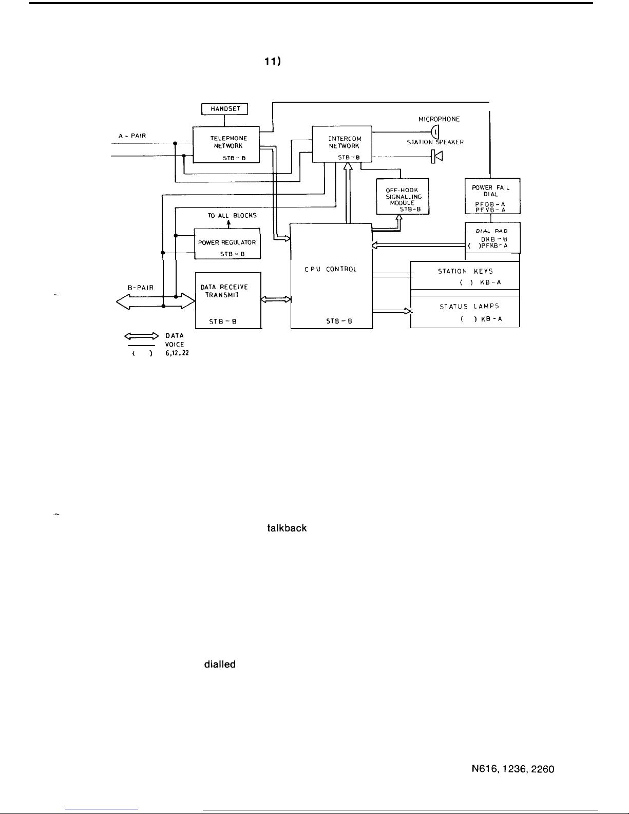
1.4.3.3 Station Block Diagram (Figure
11)
7
1
MICROPHONE
I.IL
^I
DKB -B
e
v
(
)PFKB-A
CPU CONTROL
STATION KEYS
( )
KB-A
>
STATUS LAMPS
STB-B
(
) KB-A
B-PAIR
DATA RECEIVE
TRANSMIT
STB-B
a
DATA
VOICE
(
I
6.12.22
FIGURE 11 STATION BLOCK DIAGRAM
Telephone Network, transmission circuit and Handset are connected to the M.E. audio path by
the A-pair.
The B-pair is used to transmit status information between the M.E. and the station and supply
power. Microphone signals for handsfree
talkback
are phantomed between the A and B pairs.
Data Receive Transmit converts transmitted data into logic levels for the CPU.
Power Regulator takes power from the B-pair to supply the station circuits.
CPU Control supervises all operations at the station, informs the main equipment of station
status and displays the status of system parameters, at the station.
Intercom Network contains the amplifiers for the station Speaker and Microphone and a solid
state switch which the CPU operates to cut-off the microphone.
Off Hook Signalling Module generates ring signaling under the control of the CPU.
Status Lamps show the status of system facilities and are controlled by the CPU.
Station Keys are used to envoke system facilities and the CPU constantly monitors their status.
Dial Pad is used to input
dialled
digits. During normal operation the operation of the dial is
monitored by the CPU and the information is conveyed to the main equipment. Under powerfail
conditions the dial pad operates the Powerfail Dial which outputs either decadic pulses or
DTMF tones onto the A-pair for signalling on the exchange line connected to that station.
N616,1236,2260
37
ISSUE 1
Page 41
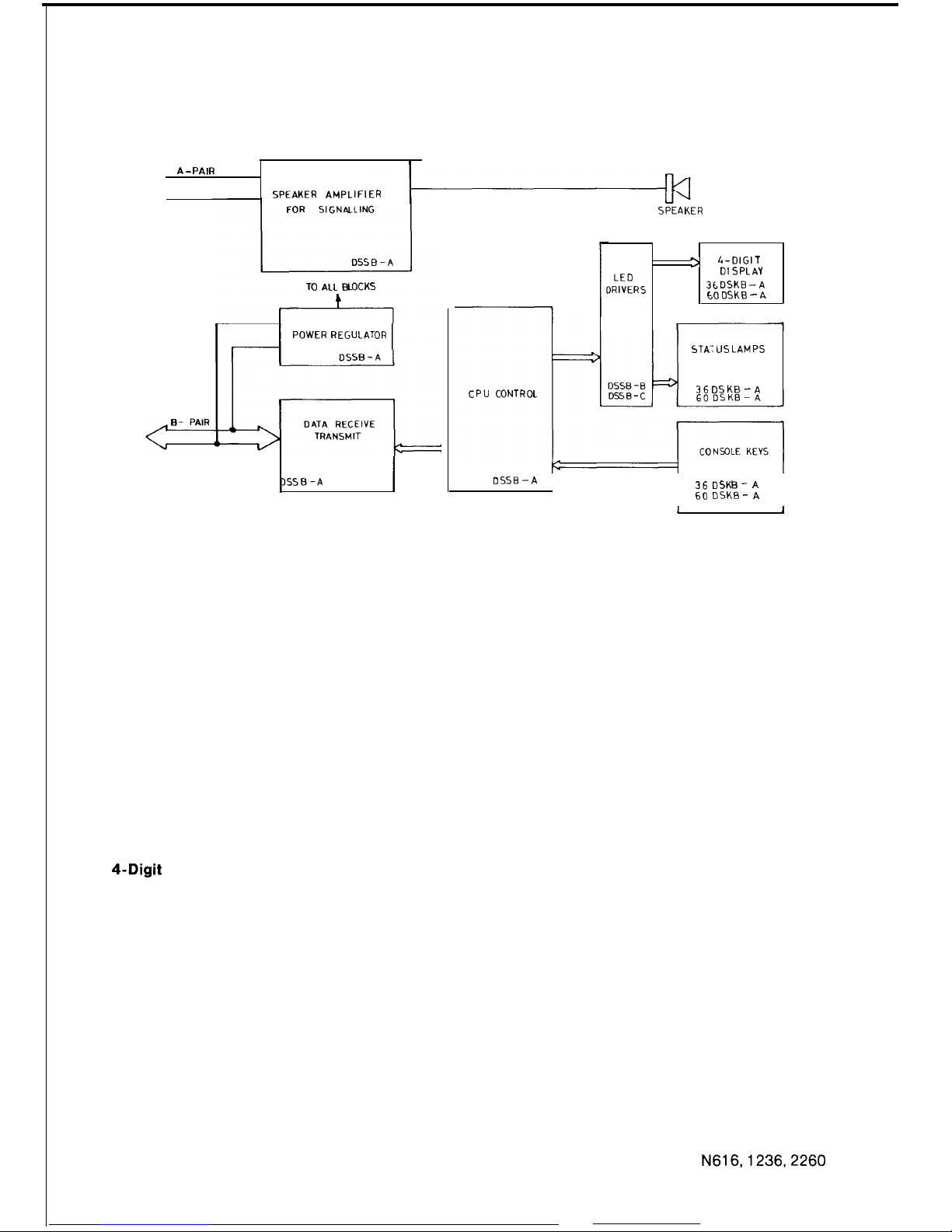
1.4.3.4
DSS Console Block Diagram (Figure 12)
A - PAIR
SPEAKER AMPLIFIER
TO
ALL BLOCKS
POWER REGULATOR
1
DSSB-A
j
i
CPU CONTROL
SPEAKER
LED
)RIVERS
> 4-DIGIT
DISPLAY
3tDSKB -A
CO
DSKB - A
STAY US LAMPS
36 DSKB -A
DSSB -A
36 DSKB-
A
60 DSKB-
A
I I
FIGURE 12 DSS CONSOLE BLOCK DIAGRAM
Speaker Amplifier and Speaker are connected to the ME by the A-pair to receive call signalling
and alarm tones.
The B pair is used to transmit key status data to the ME and receive lamp data from the ME.
Data Receive Transmit block converts transmitted data into logic levels for the CPU.
Power Regulator takes power from the B-pair to supply the DSS console circuits.
CPU Control scans the DSS console keys, transmits DSS console status to the ME, and
interprets data from the ME to control LEDS.
LED Drivers decode outputs from the CPU to drive LEDS in the DSS console keys and the four
digit displays.
4-Digit
Display uses seven-segment LEDS to display programming or held line information.
Status Lamps in the DSS Console keys show station and key function status.
Console Keys are used to evoke system facilities and to program system data.
N616,1236,2260
38
ISSUE 1
Page 42
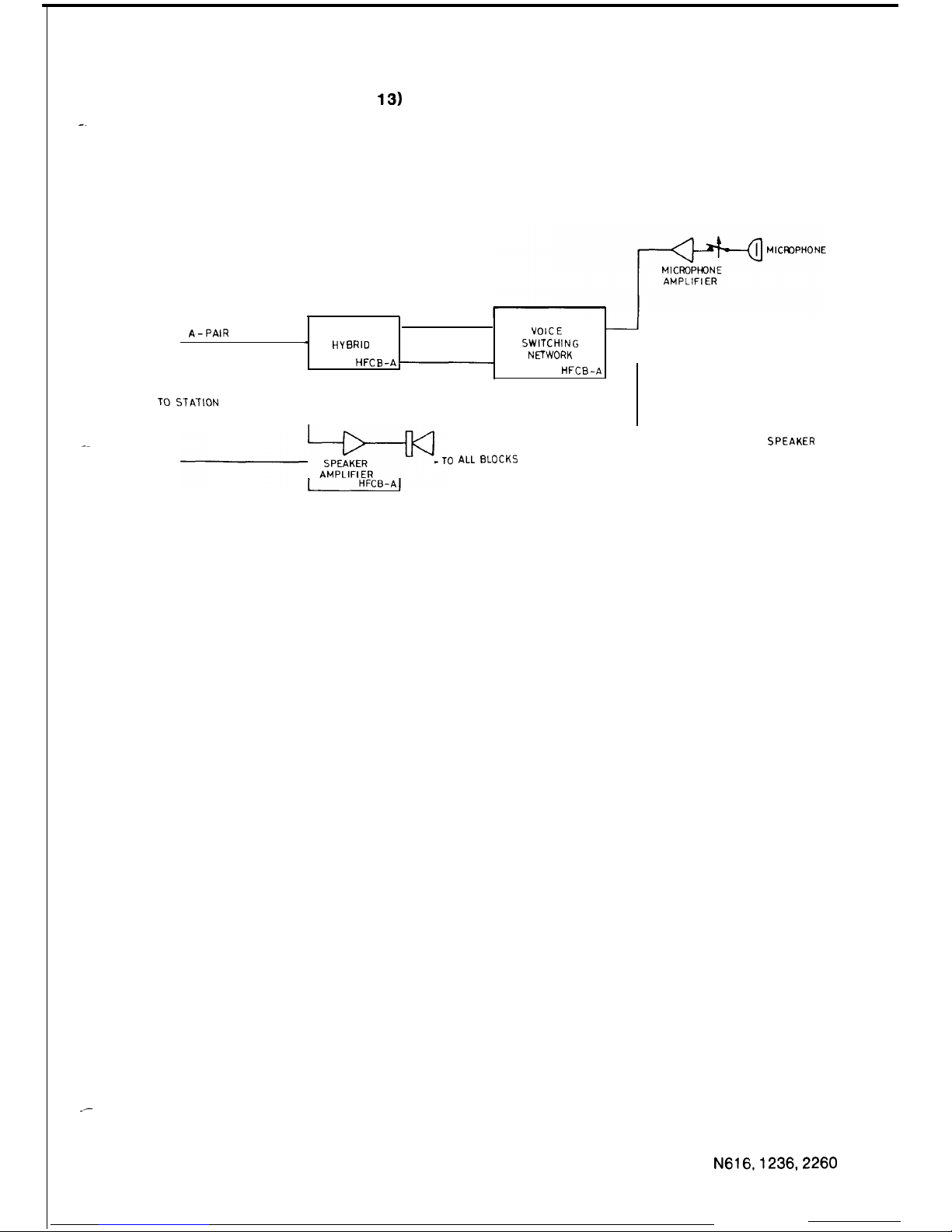
1.4.3.5 Handsfree Console (Figure
13)
--
_-
A-PAIR
VOICE
-
HYBRID
SWITCHING
NETWORK
HFCB -A p
HFCB-A
TO STATION
pf=j+TO
ALL BLOCKS
w
SPEAKER
FIGURE 13 HANDSFREE CONSOLE BLOCK DIAGRAM
The handsfree console is connected to a station to allow a call to be originated without using the
handset.
Hybrid is connected to the main equipment via the station A-pair and provides a 2 wire to 4 wire
conversion.
Power Regulator takes power from the station to supply handsfree console circuits.
Voice Switch Network is connected between the microphone and speaker and the hybrid to
prevent the handsfree console from singing. A noise operated gain adjusting device prevents
the microphone switching on in a noisy environment.
Microphone Amplifier is switched on by the key on the handsfree console.
The Speaker Amplifier is connected to the voice switch.
N616,1236,2260
39
ISSUE 1
Page 43
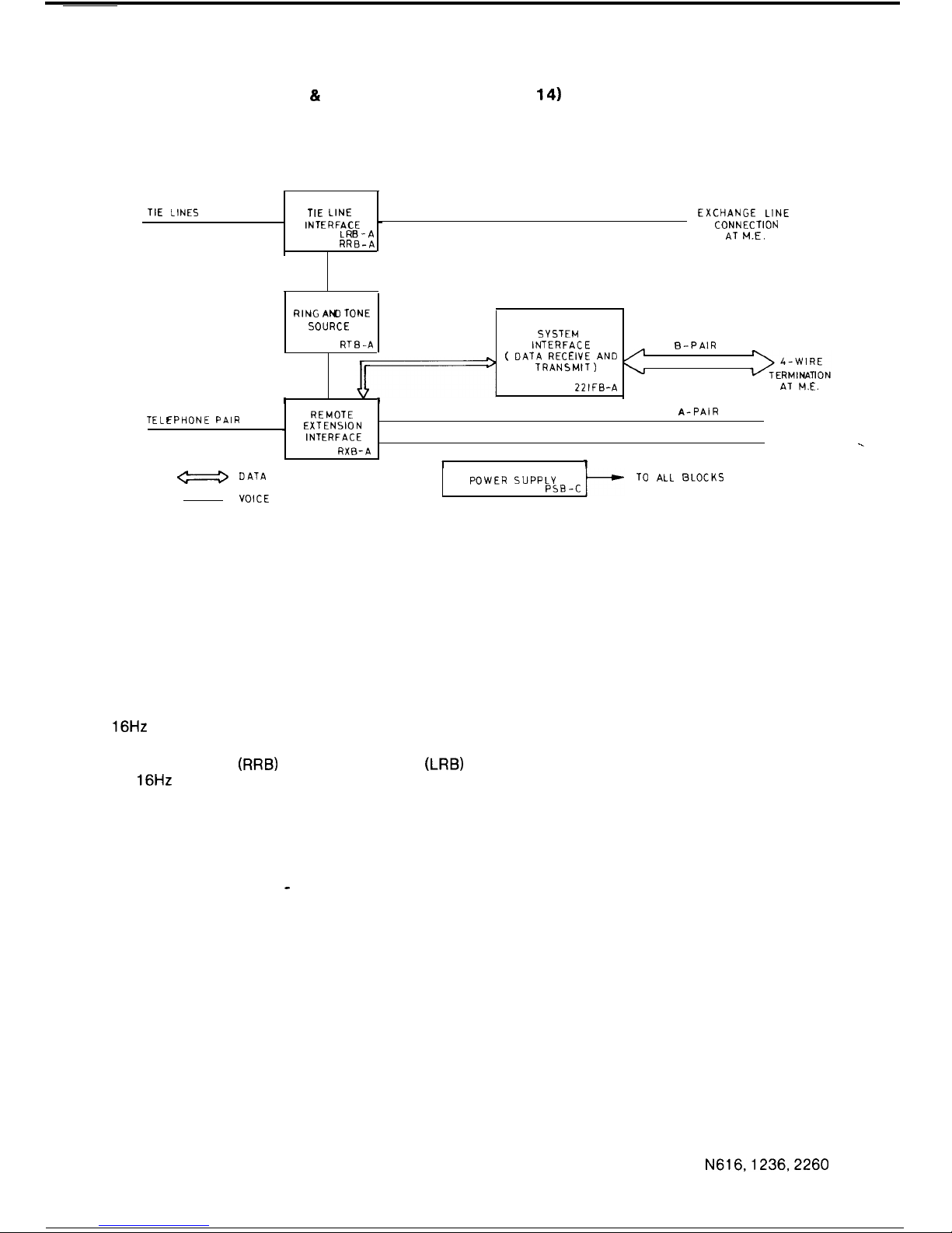
1.4.3.6
Remote Extension & Tie Line Interface Unit (Figure
14)
TIE LINES TIE LINE
EXCHANGE LINE
INTERFACE
-
CONNECTION
LRB-A
AT M.E.
RRB-A
RING AN) TONE
SOURCE
SYSTEM
RTE-A
INTERFACE
B-PAIR
( DATA RECEIVE AND /
TRANSMIT)
\r
22 IF&A
AT M.E.
1
I
TELEPHONE PAIR
REMOTE
A-PAIR
. EXTENSION
INTERFACE
RXB-A
I
1
s
DATA
VOICE
POWER SUPPLY
PSB-c
TO ALL BLOCKS
FIGURE 14 REMOTE EXTENSION AND TIE LINE
INTERFACE UNIT BLOCK DIAGRAM
Ring and Tone Source provide two oscillators, one for busy tone and ringing signal cadence. A
16Hz
60V generator is provided for signalling.
Tie Line Interface is always loop in, ring out from the main equipment. It can be either
Ring-in/Ring-out,
(RRB)
or Loop-in/Ring-out
(LRB)
from the tie line. The tie line interface uses
the
16Hz
signal for ringing and sends ring back tone to the main equipment or tie line.
Remote Extension Interface connected a 2 wire decadic telephone to the A-pair audio path. A
CPU interprets decadic signalling from the remote extension and controls ringing signals for the
remote extension.
System Interface controls data transmission to the main equipment via the B-pair. The same
CPU is used as in a normal station. Keys are simulated by ROM under control of the Remote
Extension Interface CPU - LED information is sent to the Remote Station Interface.
-.
N616,1236,2260
40
ISSUE 1
Page 44
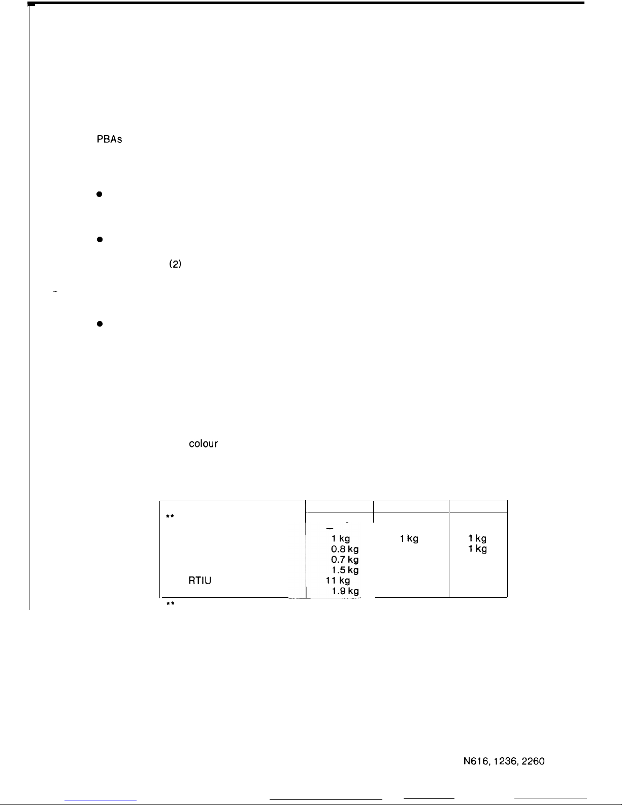
1.5 MECHANICAL DESCRIPTION
1.5.1
EQUIPMENT DRAWINGS
All of the main system components are shown in figures 15 to 28. The drawings show location of
PBAs in the main equipment racks, fuses, switches, and alarm lamps on the power supplies,
overall dimensions and locations of cords, plugs, sockets, earthing connections and station
controls.
1.5.2
ASSEMBLY AND DISMANTLING INSTRUCTIONS
0
Main Equipment, RTIU, RGU, CMU
Turn the power off, then loosen screws on the cover to remove covers and gain access for
installation and maintenance.
0
DSS Console
Unplug the DSS console then carefully remove the front panel using a screwdriver. Loosen
the screws
(2)
fixing the top case moulding to the base moulding and lift off the top case.
The bracket retaining the keys and display board may be lifted up.
-
The line cord may be removed by removing the quick connect terminals and the line cord
retainer, then draw the cord through the base moulding. Refer to fig. 67.
0
Stations
Unplug from socket, then carefully remove front panel using a screwdriver. Loosen the
screws (2) fixing the top case moulding to the base moulding and lift off the top case. The
bracket retaining the dial pad and keys may be lifted up.
The line cord or handset cord may be removed by removing the quick connect terminals
and the cord retainer, then drawing the cord though the base moulding. For re-assembly
refer to figs. 49 a 50.
To change the transmitter or receiver,
unscrew the handset moulding, remove the
anti-static sheet and transmitter or receiver. Ensure that the anti-static sheet is replaced
with the insert.
If a woodgrain
colour
panel is to be replaced by an orange or brown one, the woodgrain
panel should be returned to the store to ensure adequate supplies are available for
maintenance and workshop use.
1.53
TABLE 3: WEIGHTS OF EQUIPMENT
**
Main Equipment
Power Supply
Station
DSS Console
Handsfree Console
Ring Generator Unit
l *
RTIU
Call Metering Unit
**
No Boards Equipped
I
N616
N 1236
25 kg 18kg
25 kg
1
kg
0.8 kg
N 2260
23 kg
25 kg
1 kg
1 kg
N616,1236,2260
41
ISSUE 2
Page 45
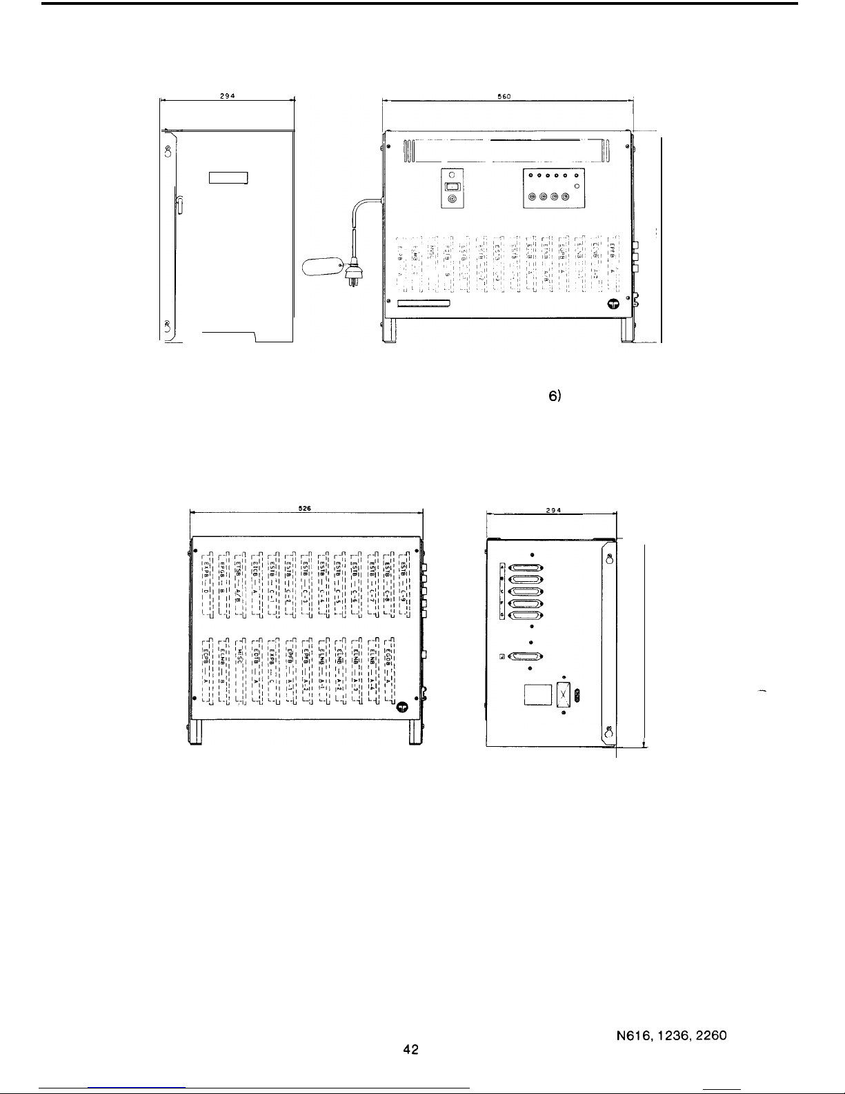
FIGURE 15 N616 MAIN EQUIPMENT (ME-61
6)
FIGURE 16 N1236 MAIN EQUIPMENT (ME-1 236)
i
-
i
N616,1236,2260
ISSUE 2
Page 46
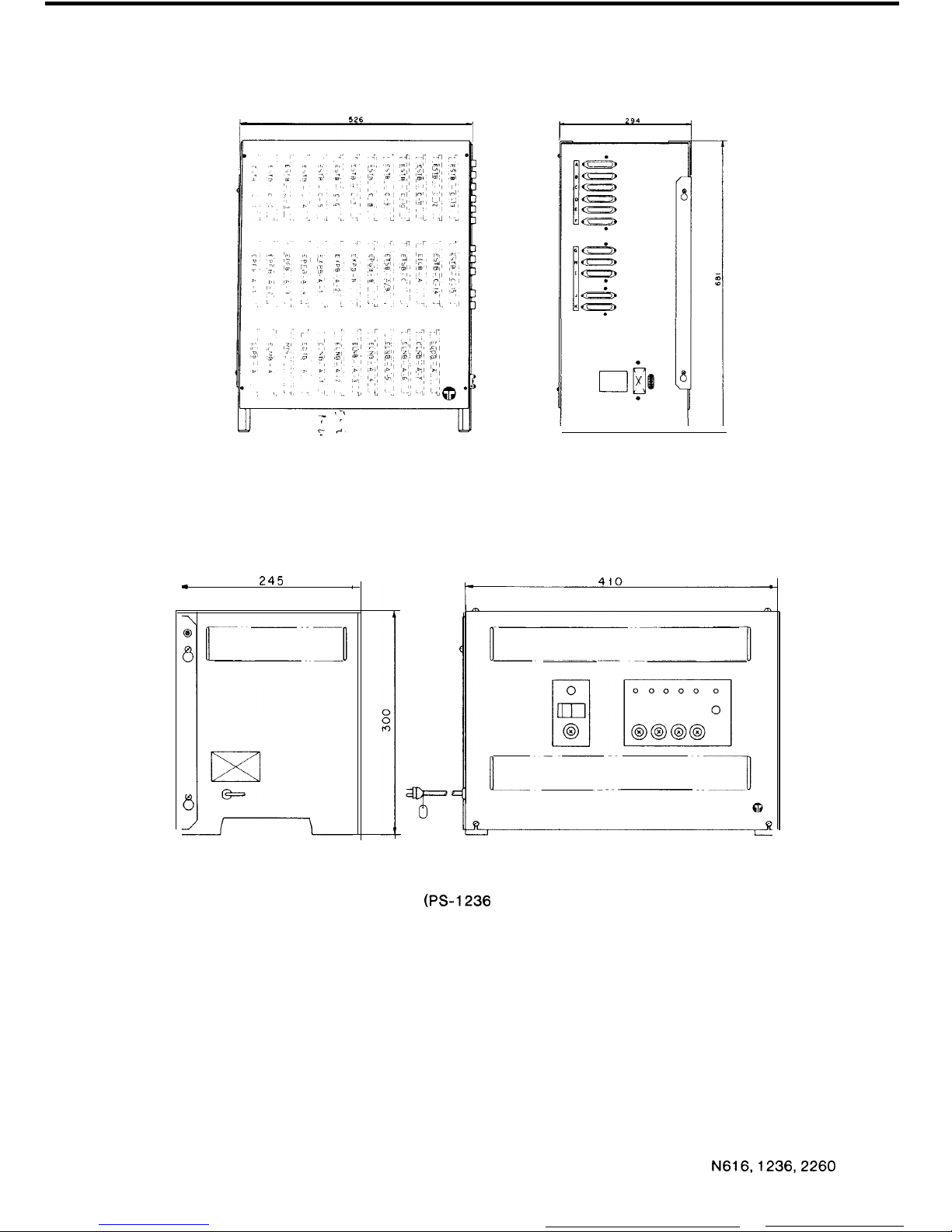
FIGURE 17 N2260 MAIN EQUIPMENT (ME-22601
.
al
x
.
245
.
,
FIGURE 18 N1236 AND N2260 POWER SUPPLY
(PS-1236
2260)
N616,1236,2260
43
ISSUE 2
Page 47
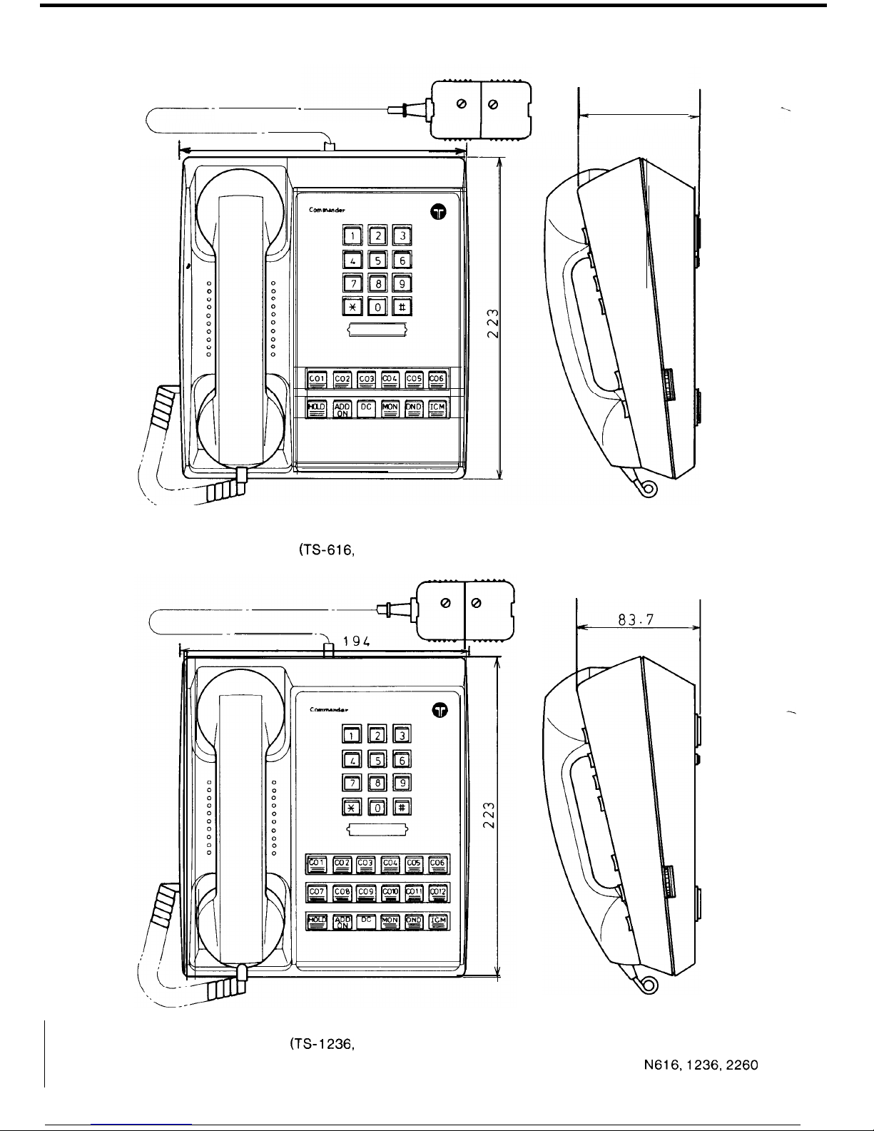
c-----
-
L-
;$
194
I I
FIGURE 19 N616 STATION
(TS-616, TS-616-PFDEC, TS-616-PFVF)
1
83.7
FIGURE 20 N1236 STATION
(TS-1236,
TS-1236-PFDEC, TS-1236-PFVF)
N616,1236,2260
44
ISSUE 2
Page 48
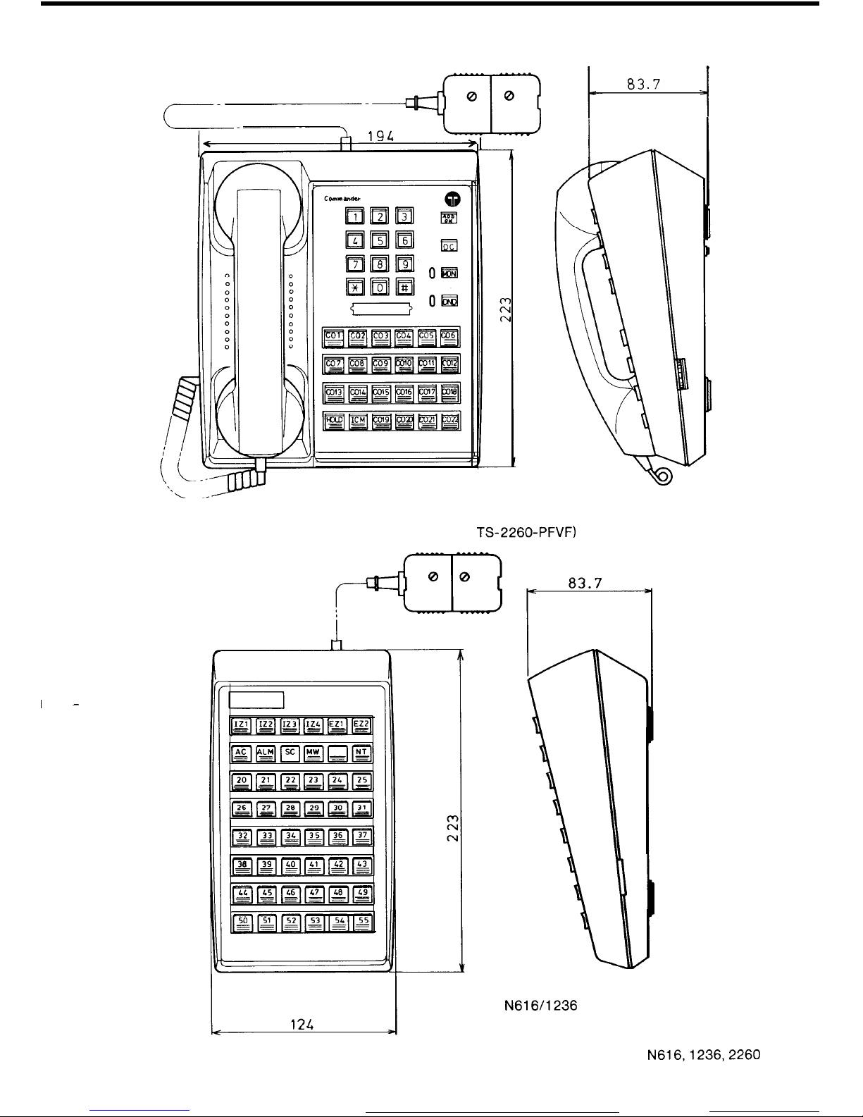
I
-
FIGURE 21 N2260 STATION
(TS-2260, TS-2260-PFDEC,
TS-2260-PFVF)
FIGURE 22
N61611236
DSS CONSOLE
(DSS-616 1236)
N616,1236,2260
45
ISSUE 1
Page 49
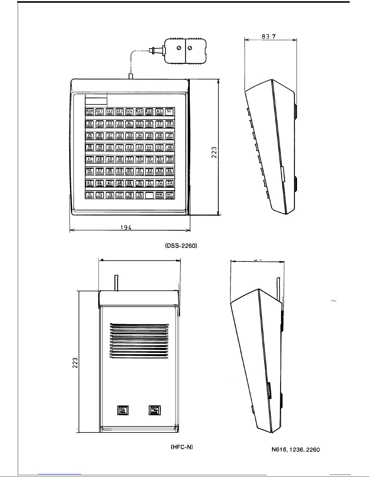
FIGURE 23 N2260 DSS CONSOLE
(DSS-2260)
.
124
.-T
FIGURE 24 HANDSFREE CONSOLE
84
1
--
N616,1236,2260
46
ISSUE 1
Page 50
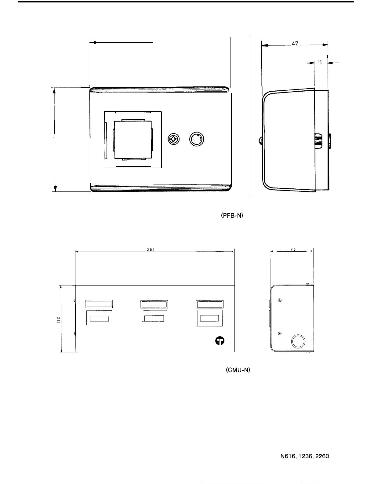
74
I
100 ---
FIGURE 25 POWERFAIL BELL (PFB-N)
I/
!Exl
lrxl
F----d
T
I
FIGURE 26 CALL METERING UNIT (CMU-N)
47_/
r
’
N616,1236,2260
47
ISSUE 1
Page 51
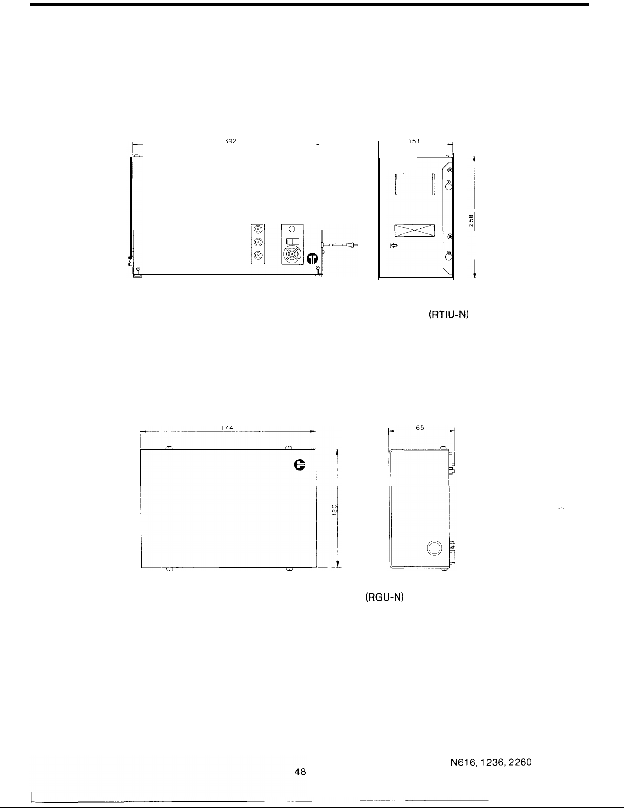
332
151
FIGURE 27 REMOTE EXTENSION AND TIE LINE INTERFACE UNIT
(RTIU-NJ
FIGURE 28 RING GENERATOR UNIT (RGU-N)
N616,1236,2260
ISSUE 1
Page 52
2
INSTALLATION
2.1
INTRODUCTION
The procedure, listed below, must be followed when installing the systems.
1.
Using the Sales Form, the necessary equipment must be ordered.
2. Mount components, Main Equipment, SDF, Power Supply, Stations, Powerfail Bell, Ring
Generator Unit,
RTIU
and Call Metering Unit.
3. Cable the site.
4. Terminate cables at M.E., SDF, 610 Sockets, Powerfail Bell, Ring Generator Unit, RTIU,
Call Metering Unit, External Music Source, External Paging Loudspeakers and Alarm
Detector.
Lightning protection must be provided.
A Telecom earth must be terminated on the Call Metering Unit.
5.
Plug boards into Main Equipment.
6. Power-up the system.
7.
Check cabling by measuring voltages at 610 sockets.
8.
Connect Handsfree Consoles to the associated stations. Plug-in stations.
9.
Programme the system using information provided on the sales form.
10.
Carry out the functional test to ensure the system is operating correctly.
11.
Write-up the site records.
Details required to perform the above procedure are described in this section.
N616,1236,2260
49
ISSUE
1
Page 53

2.2 SALES INFORMATION
The Telephone Order for any S.B.S. will be accompanied by an S.B.S. System Order.
Sales staff, after consultation with the customer, complete the System Order.
The information provided in this form will enable the ordering of the various items required for
the installation. It also provides information required when programming the system.
Three copies of the System Order are forwarded to the installation area.
On completion of the installation any variation to the System Order should be noted on each
copy of the order. One copy of the System Order should remain with the equipment to provide a
record of the particular installation. The remaining two copies should be returned to the local
Telecom Business Office.
-\.-_ .
/-
N616,1236,2260
ISSUE 2
‘1
Page 54
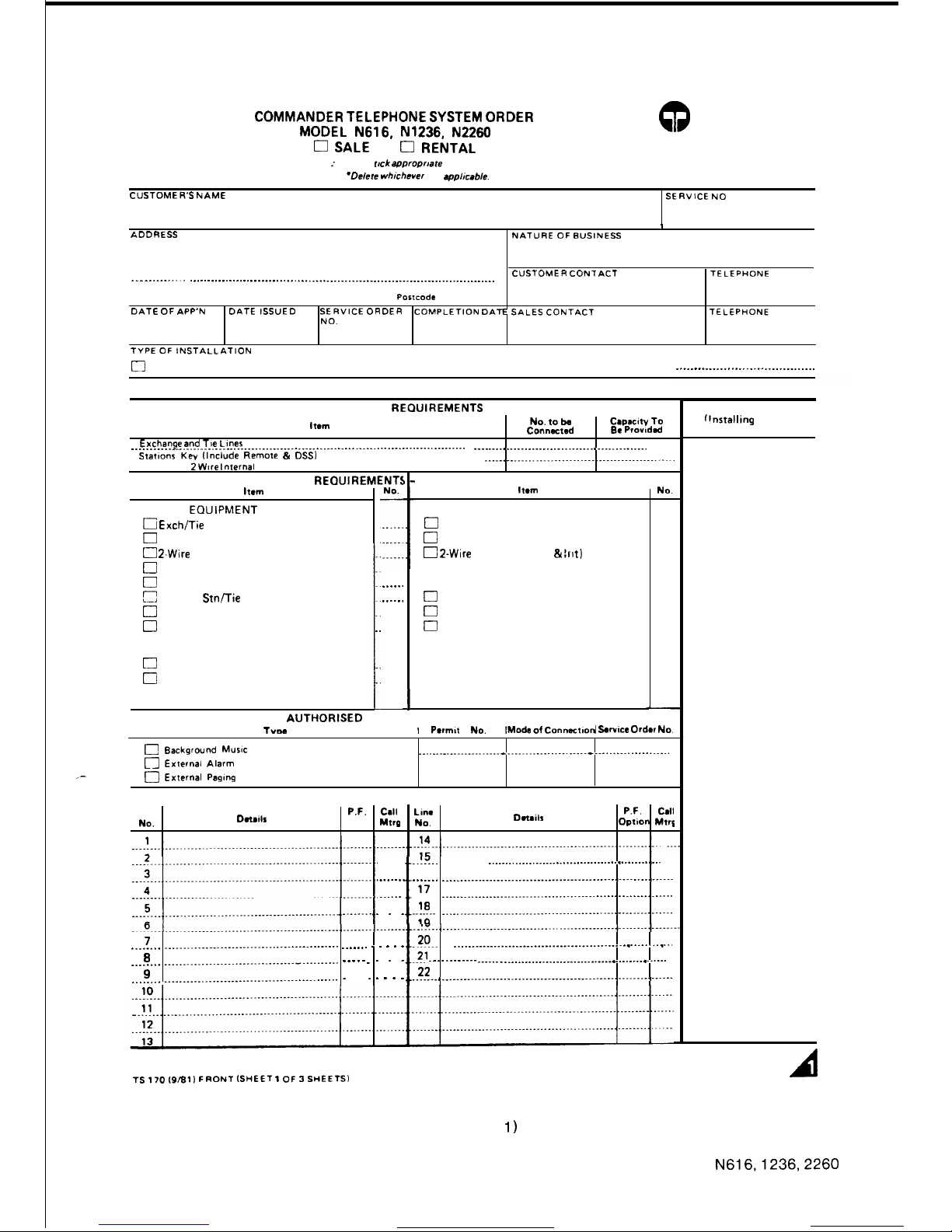
43
Telecom Australia
COMMANDER TELEPHONE SYSTEM ORDER
MODEL
N616,
N1236, N2260
0 SALE
0 RENTAL
NOTE :Please trek
a~~roprmte
boxes
‘Odete
whrchcver not applicable.
CVSTOMER’S NAME
SERVICE
NO
I
ADDRESS
NATURE
OF
9”SlNESS
CUSTOMER CONTACT TELEPHONE
. . . . .._........ . . . . . . . . . . . . . . . . . .
..~.........................................................~.....
POslCOde
DATE
OF APP’N
DATE ISSUED
SERVICE ORDER
COMPLETION DATE
SALES
CONTACT TELEPHONE
NO.
TYPE
OF
tNSTALLATlDN
0
NEW
q REMOVAL SERVICE q REPLACES (Specify type and model)
.__..___......___.....................
SUMMARY OF SYSTEM REQUIREMENTS
CAPACITY RECIUIREMENTS
Item
No.
to be
Capacity To
Connaad
Etc Prowdcd
Exchange and Tte
Loner
___________. . . . . . . . . . . . . . .
..~.~.........~...........................~~.....~~~~~~~~....~~~~~
. . . . .._.._....__..._......................-.....
Statmnr
Key llnclude Remote & DSSI
_____.__...._.._..__..........,...................~.
2 Wtre Infernal
EQUIPMENT
REOUIREMENTS
hml
CENTRAL
EDUIPMENT
[?
Exch/Tie Line Modules
0
Key Station Modules
0
2.Wire Int. Station Modules
0
Addit’l Intercom Links Module
0
External Paging Module
2
Remote
Stn/Tie
Line Interface Unit
0
Remote Station Modules
0
Tie Line Connector Modules
SYSTEM OPTIONS
0
Call Metering Unit
0
Powerfail Bells
t
.
.
1
_.
(Additional To Basic Provided)
Imm
STATION INSTRUMENTS
0
Powerfail Stations
0
Key Stations
0 2-Wire
Stations (Rem &
Irrt)
......
......
STATION ATTACHMENTS
[7
DSS Consoles
0
Handsfree Consoles
0
Wall Mounting Kits
I
AUTHORISED
ATTACHMENT CONNECTIONS
NO.
TVW
I
Pmn,t
No.
Mode of
Connsctmd .Swwce Order No.
[3
Background
MUSIC
n
Externai
Alarm
. . . . . . . . .._.............-..............-.-.-.-------.-..--..-.-.-----.
,-
0
External
Pagang
EXCHANGE/TIE LINE CONNECTIONS
Line
NO.
Dnails
P.F.
Cdl
LllW
P.F.
Cdl
Option
Mtrg
NO.
Dnailr
Option Mtrg
. . . .
f
..!.-1..
. . . . . . . . .
.._..._.___........................................
16
.___..__
.._.... _______........__..............................,...............
17
..____
. . . . ______._____________...........................................
I
I
_.__.._.. .
.
‘8 _____.__...__.........................~........................
. . . . . . .
10
_.______ .___....____._._____...............~.~......... ..____. . . . . .
t
20.. ______......._.__.._..........................~.............
8
___..... ______.._____._._.._.~.........~...-.........-
. . . . . . . . .
..?! . . . . . . . . . . . .
.._.._ _ ___________._._.__.........~.~~.....~..~.......
9
22
_______. __________..________........................---
. . . . . .
_______,________.__....____...........~......~.....~...................
EQUIPMENT CODE
rrnstalling
Officer
Only)
TS 170 (9/8i)
FRONT (SHEET I of ~SHEETS)
BUSINESS OFFICE COPY
A
FIGURE 29 SBS SYSTEM ORDER.
(SHEET
1)
N616,1236,2260
51
ISSUE 1
Page 55

EXPLANATORY NOTES
1. COMP. DATE : To be inserted by installing Officer on completion of installation.
2. SALES CONTACT : Sales Officer conducting negotiations with customer.
3. CAPACITY REQUIREMENTS : Show total number of lines and stations to be
connected and the system capacity required to cater for these.
4. EQUIPMENT REQUIREMENTS : Show number of Modules, additional to the
basic tariff package, required in the central equipment to provide the required
system capacity.
5. EXCHANGE/TIE LINE CONNECTIONS -DETAILS
(i) Exchange Line - show exchange number
(ii) Tie Line
-
show equipment type and exchange number at distant
end.
Specify whether Power Fail Bell or Power Fail Station is to be provided.
Indicate using ticks, those lines on which call metering equipment is to be provided.
TS
170 i9/80
BACK
(SHEET 7
OF
3SHEETS)
52
N616,1236,2260
ISSUE.1
Page 56
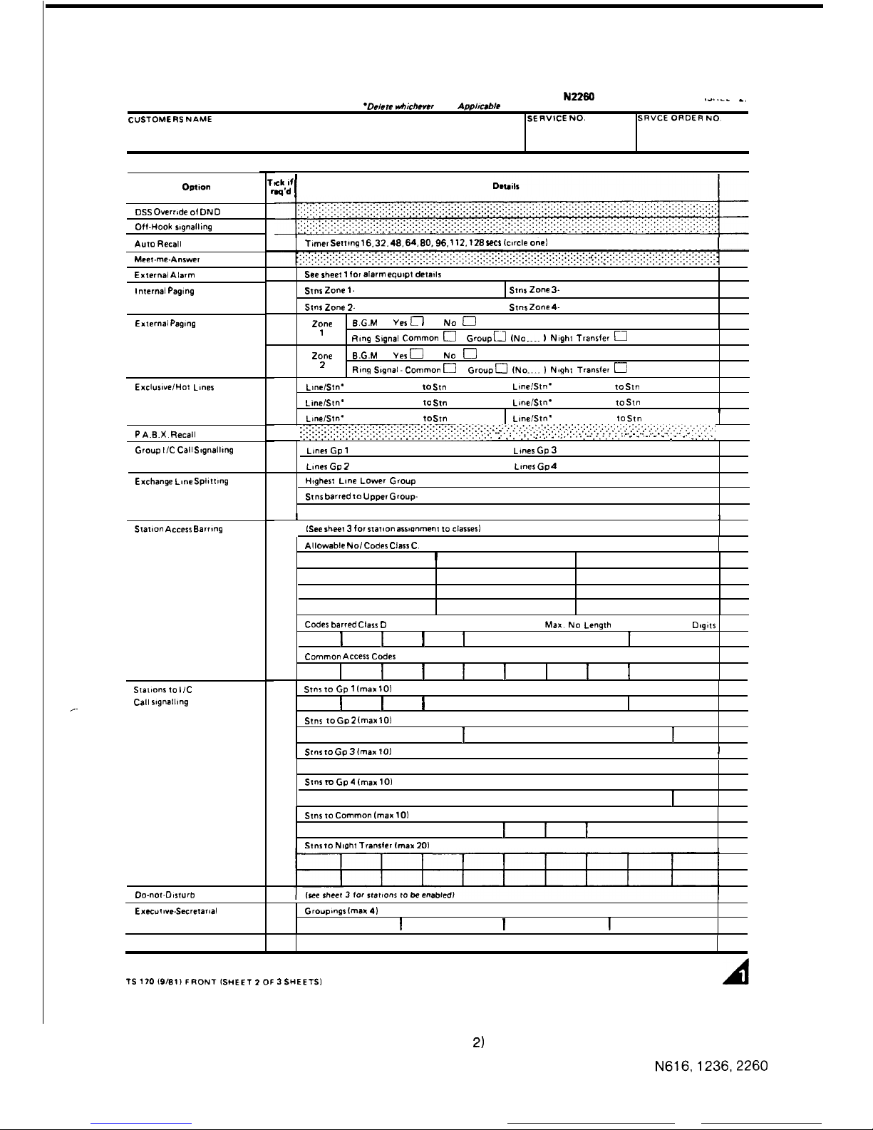
COMMANDER TELEPHONE SYSTEM ORDER MODEL N616, N1236, N2260
Id..-- -,
NOTE
*Delete
vhichever Not
Ap#mble
CUSTOMERS NAME
SERVICE NO.
SRVCE ORDER
NO.
PROGRAMMABLE OPTIONS
Option
11
n
OSS
Overr,de of
OND
Off-Hook s,gnall,ng
Auto
Recall
Meet-me-Answer
External
Alarm
See sheet 1
for alarm eqwpt detatls
Internal
Pagtng
External
Pagong
Exclus~ve/Hot
Lines
P A.B.X.
Recall
Group
I/C
Call
S~gnall~ng
Exchange
Lune
Sphttlng
Statm” Access
Barring
Stations to
I/C
Call
slg”alll”g
,-
Do-not-Oeturb
Executw-Secretanal
lck
If
=id
I
Tamer
Settvng
16.
32. 48, 64, 80,96,
112. 128
sea lc~rcle
onei
stnr
Zone
l-
stns Zone 3.
stnr
Zone 2.
stns Zone 4-
-
-
Zone
8.G.M
Yes L I
No
t-i
1
Rang Signal
Common
0
Groupu (No.... ) Naght
Transfer
u
Zone
8.G.M
Yes
0
No
0
2
Ftlng Stgnal -Common 0
GroupO (No.... I Neght
Transfer
0
Ll”e/St”’
to
St”
Llnelst”’
to
St”
Llnelst”’
to
St”
Llneist”’
to
St”
1
Llnelst”’
tcl St”
Llnelst”’
to
stn
~.~.~.‘.‘.~.‘.‘.‘.‘.‘.~.~.~.~.‘.’.~...~.~.~.~.~.‘.~.~.~...~.~.~.~.:.‘...‘...~.:.:.:.~.,.~.~.,.,.,.~...,.,.,.,.,.,.~.,.,.,.,.,.....,~,...,.
~.~.~.~.~.~.~.~.~.~.~.~.~.~.~.‘.’.~...~.~.~.~.~.‘.‘.~.~.~.
:. . . . . . ..::_: .~.,......‘..,~,~................,.,.,.,...,....~.~....,~,.,.,.
~.......~...~.~.~...~.~.......~.~.~.......~.~.....~...~.~.~.’.~. . :. :. . . .
.
.,. .,.,.,.,.,. . . . . . . . . . . . . . . . . . ,.,.,..
Lines
Gp
1
Lunes
Gp 2
Highest Line Lower Group
Stns
barred to Upper Group-
Ames
Gp 3
lanes Gp 4
I I
ISee sheet 3
for
statoon
asswnmem to
classesl
Allowable
No/ Codes Class C.
I
I
I
Codes
barred
Class
D
Max. No Length
Dtgtts
I
I
I
I
I
I
I
I
I
Common
Access Codes
I
I I
I
I
I
I
Stnr to Gp 1 (max 10)
I
I
I
I
I
I
I
I
Stns
to
Gp 2 lmax 10)
I
I I
I
I I
I
I
I
Stns
to Gp 3 fmax 10)
I
I
I
I
I I
I
I
I
I
Stnr tu Gp 4 (max
101
I
I I
I
I
I I
I
I
Stns to Common (max
101
I
I I I
I
I
I
I
I
Stns
to Nmht Transler fmax
201
Groupmgs
lmsx 4)
I I
I
TS170f9/9t)FRONTlSHEET?OF
JSHEETSI
BUSINESS OFFICE COPY
A
FIGURE 30 SBS SYSTEM ORDER.
(SHEET
2)
N616,1236,2260
53
ISSUE 1
Page 57

.- __
EXPLANATORY NOTES
Where the option is required ensure details on right hand side of sheet are completed.
An extra sheet should be used if space on one sheet is insufficient. Further explanations
of details required are :
(i) INTERNAL PAGING
show numbers of lowest and highest stations in
each zone (e.g 20 27, 28-33, etc)
(ii) EXCLUSIVE/HOT LINE
Exclusive Line
delete “Stn” and show Line
number (from sheet 1) and station number.
Hot Line - delete “Line” and show both station
numbers.
(iii)EXECUTlVE-SECRETARIAL -
show groupings with executive station number
first
(e.g
27 .29 where 27 “executive”
statiora
and 29 the “secretarial” station).
TS
170 mm0
BACK
(SHEET
2 OF
3StiEE-n)
N616,1236,2260
ISSUE 1
Page 58
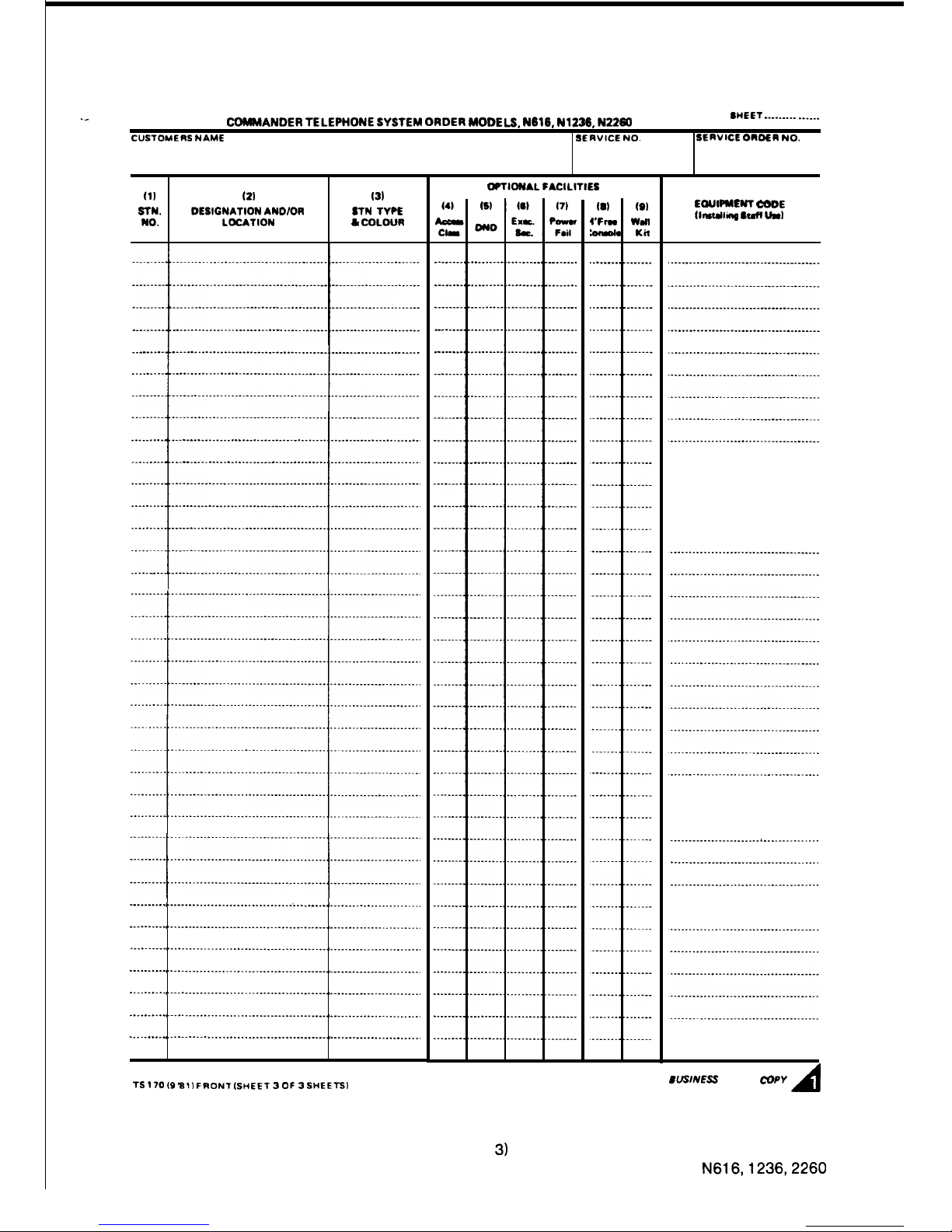
._
CDMMANDER TELEPHONE SYSTEM
ORDER
MODELS, N618,
Nl226,
N2260
SHEET .________ _____.
CUSTOMERS NAME
SERVICE NO.
SERVICE OllOEl NO.
(11
I21
(3)
STN.
DESGNATION
AND/OR
STN TVFE
NO. LOCATION
k
COLD&JR
................................................................................
...............................................................................
...............................................................................
...............................................................................
...............................................................................
...............................................................................
...............................................................................
TS
170 (S’S0 FRONT (SHEET
3 OF 3
SHEETS)
MJSINESS
OFFICE
COPY
A
OPTIONAL FACILITIES
w
(9)
I’Fm Wall
bmoh
Kil
.______....______
EOUIPMENT
CODE
wkstdling sutr lJd
........................................
........................................
........................................
FIGURE 31 SBS SYSTEM ORDER.
(SHEET
3)
55
N616,1236,2260
ISSUE 1
Page 59
EXPLANATORY
NOTES
COLUMN 1- Station numbering begins at 20.
COLUMN 2 - Show location and/or name of station user e.g., MNGR
STORE,
JONES 1st FL.
COLUMN 3
Key Stns Show Key or P/Fail and panel colour i.e. WG (Wood Grain)
BR (Brown) or OR (Orange)
2 Wire Stns - Show REM
(Remote)or
INT (Internal) and instrument
type and colour
leg.
CF Ivory)
COLUMN 4 -- Designate required Access Class i.e. A,
B, C,
D, or E.
COLUMN 5 - Tick
(J)
where required.
COLUMN 6 - On Executive Station designate Secretarial Station e.g. 25 SEC. Cross
reference Secretarial Station to Executive Unit e.g. 22
Ex.
COLUMN 7- Designate associated exchange line No. eg. L. 1.
COLUMNS
8AND9
-
Tick
(J)
where items required.
NOTE :
1.
DSS consoles utilize station numbers and must be shown in column 3
immediately following the station with which it is associated.
2. The DSS console on an N616 system may be allocated station number
36. This station number cannot be used for telephone stations and is
provided exclusively for provision of a DSS console.
TS
170 (9180 SACK lSHEET3
OF 3
SHEETS)
56
N616,1236,2260
ISSUE
1
Page 60
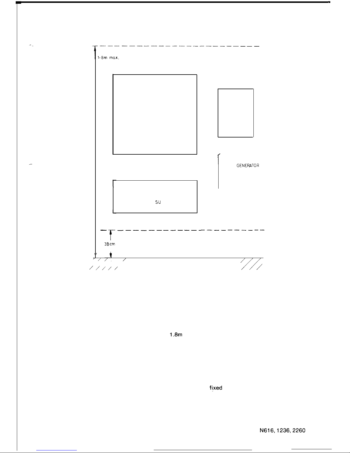
.
2.3 LOCATION AND MOUNTING OF EQUIPMENT
7
V
I
7, ,’
/
FLOOR LEVEL
//I//
MAIN EQUIPMENT
SYSTEM
DISTRIBUTING
FRAME
r
OPTIONS
POWER
. RING
GENEFUlOR
UNIT
. CALL METERING
UNIT
su
PPLY
f
_--_--__-------------
38cm
min.
I
FIGURE 32 LIMITATIONS ON WALL MOUNTING
All items of equipment must be located in positions which allow good access for maintenance
activities. The customer is responsible for providing satisfactory lighting for installation and
maintenance activities at the equipment. When wall mounting equipment, allowance should be
made for at least 30 cm clear wall space on each side and 1 metre of clear floor space in front of
the units.
The Main Equipment, Power Supply, System Distributing Frame, Call Metering Units, Remote
Extension and Tie Line Interface Unit and Ring Generator Unit must be mounted on a wall at
least 38 cm from the floor and no higher than
1.8m
from the floor as indicated on figure 32.
The customer will provide a single phase 200-250 volt, 10 amp, 50 Hz AC general purpose
outlet within 1 metre of the equipment. The power outlet must be correctly earthed.
Due to the weight of the equipment, particularly the Power Supply, care should be exercised in
the selection of the mounting position.
Both the Main Equipment and the Power Supply are to be wall mounted as shown in figure 32.
Equipment may be mounted directly to solid brick walls or similar. For hollow structures, such
as plaster-board walls or partitions, a suitable sized back-board should be firmly secured to the
wall studs (or other supporting members) and the equipment
ft,xed
to the back-board.
Where equipment is to be mounted on solid brick walls or similar, suitable masonary anchors
should be used in lieu of the mounting screws.
Further mounting details for the Main Equipment and Power Supply are provided in section
2.3.1 and 2.3.2 respectively.
While mounting equipment refer to the drawings of the components in section 1.5.
N616,1236,2260
57
ISSUE 1
Page 61
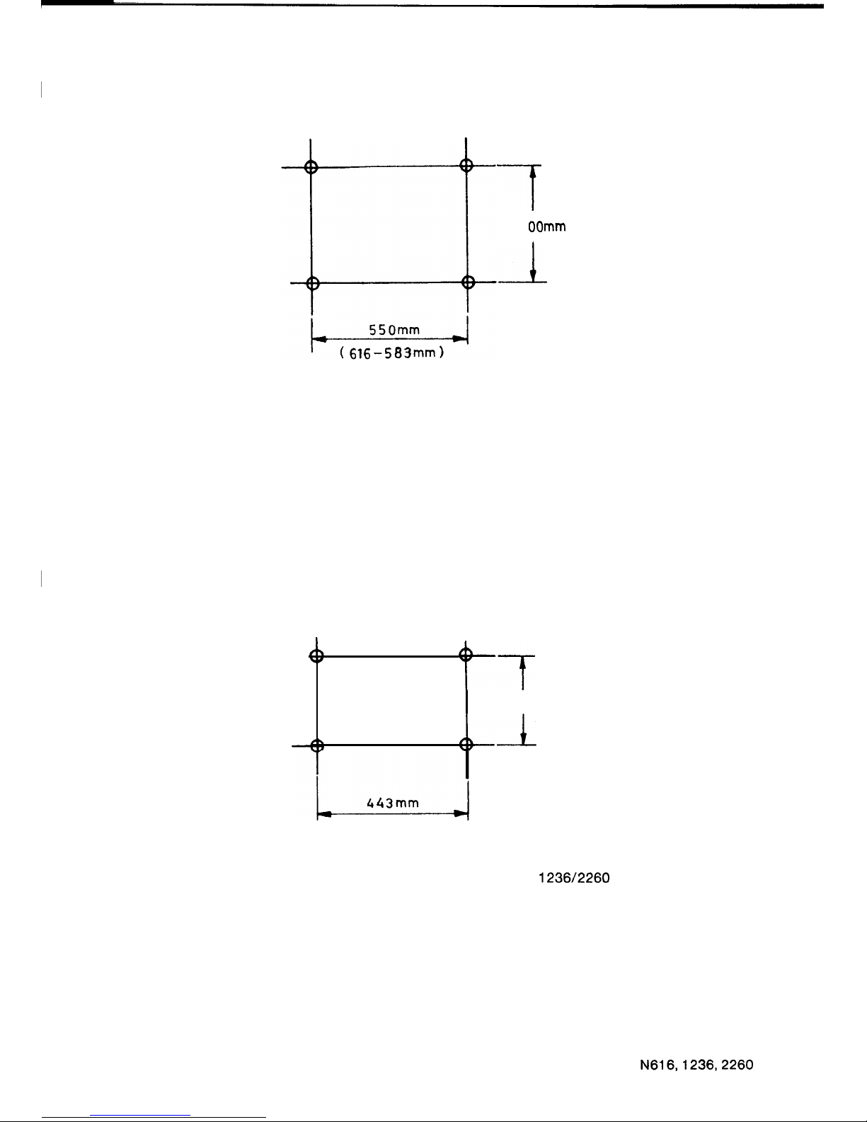
2.3.1 Main Equipment
7
4
OOmm
I
FIGURE 33 MOUNTING FOR MAIN EQUIPMENT
The cabinet is wall mounted. To mount on the wall, drill four holes in the locations shown in
figure 33. Insert mounting screws in the holes. Remove the two wall mounting brackets from the
rear corners of the cabinet. Reassemble, with bracket sides containing the two tear drop holes
projecting out from the side of the cabinet, refer to figures 15 to 17.
Hang the cabinet on the screws using the tear-drop holes provided in the wall mounting
brackets, then, tighten the screws.
2.3.2 Power Supply
.”
+f
200mm
:+L
FIGURE 34 MOUNTING FOR POWER SUPPLIES
1236/2260
The power supply is wall mounted. Drill four holes in the locations shown on figure 34. Insert
mounting screws into the holes. Change over the wall mounting brackets screwed on the rear
corners of power supply, as described above for the main equipment, and hang the power
supply on the mounting screws using the tear-drop holes. Tighten the screws.
58
N616,1236,2260
ISSUE 2
Page 62
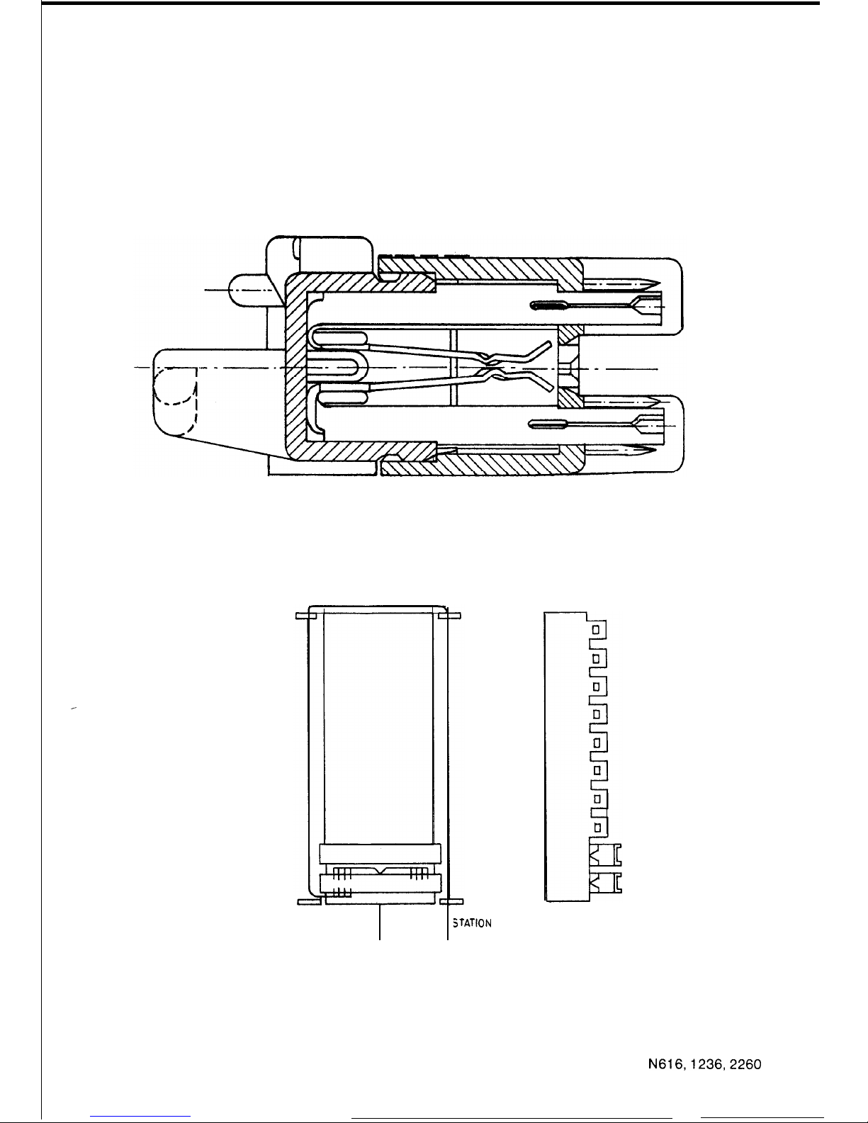
2.3.3
System Distributing Frame
The S.D.F. provides a common terminating point for the main equipment, stations and other
ancillary equipment. It also provides for any strapping necessary for provision of facilities.
The S.D.F. is constructed using the Krone LSA Plus terminating system. The terminal is an
insulation displacement type terminal and is available in 10 pair modules. The modules provide
the facility of opening the circuit for monitor or test purposes without the need to disturb the
terminations. See figure 35.
FIGURE 35 KRONE DISCONNECTION MODULE
(SIDE ELEVATION)
MAIN EQUIPMENT CABLES
STATION
CABLES
FIGURE 36 BACKMOUNT CHANNEL CABLE LAYOUT
The modules are mounted on a backmount channel. Each channel will accept 10 modules, thus
giving a total capacity of 100 pairs. See figure 36.
N616,1236,2260
59
ISSUE 1
Page 63
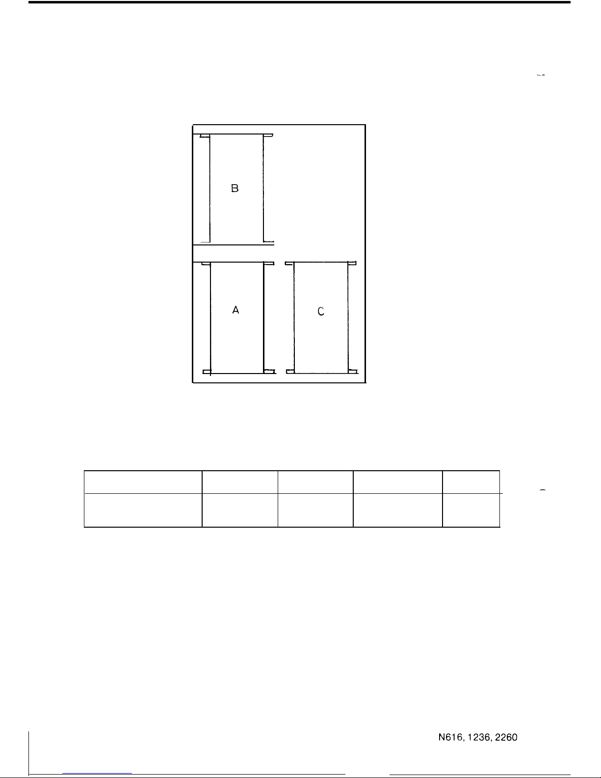
Backmount channels can be mounted using either the backmount channel mounting frame or
on a suitable sized backing board.
When more than 100 pairs are necessary, an additional backmount frame should be fitted in
accordance with the layout shown in figure 37.
.--
FIGURE 37 S.D.F. BACKMOUNT CHANNEL LAYOUT
TABLE 4: S.D.F. Terminal Requirements For Each System
SYSTEM
S.D.F. SIZE
TERMINATED
AMP CHAMP KRONE
PAIRS CONNECTORS MODULES
Commander N616 100 pairs 75
3 8
N1236 200 pairs 150
6
15
N2260 300 pairs 275
11
28
-
N616,1236,2260
60
ISSUE 1
Page 64
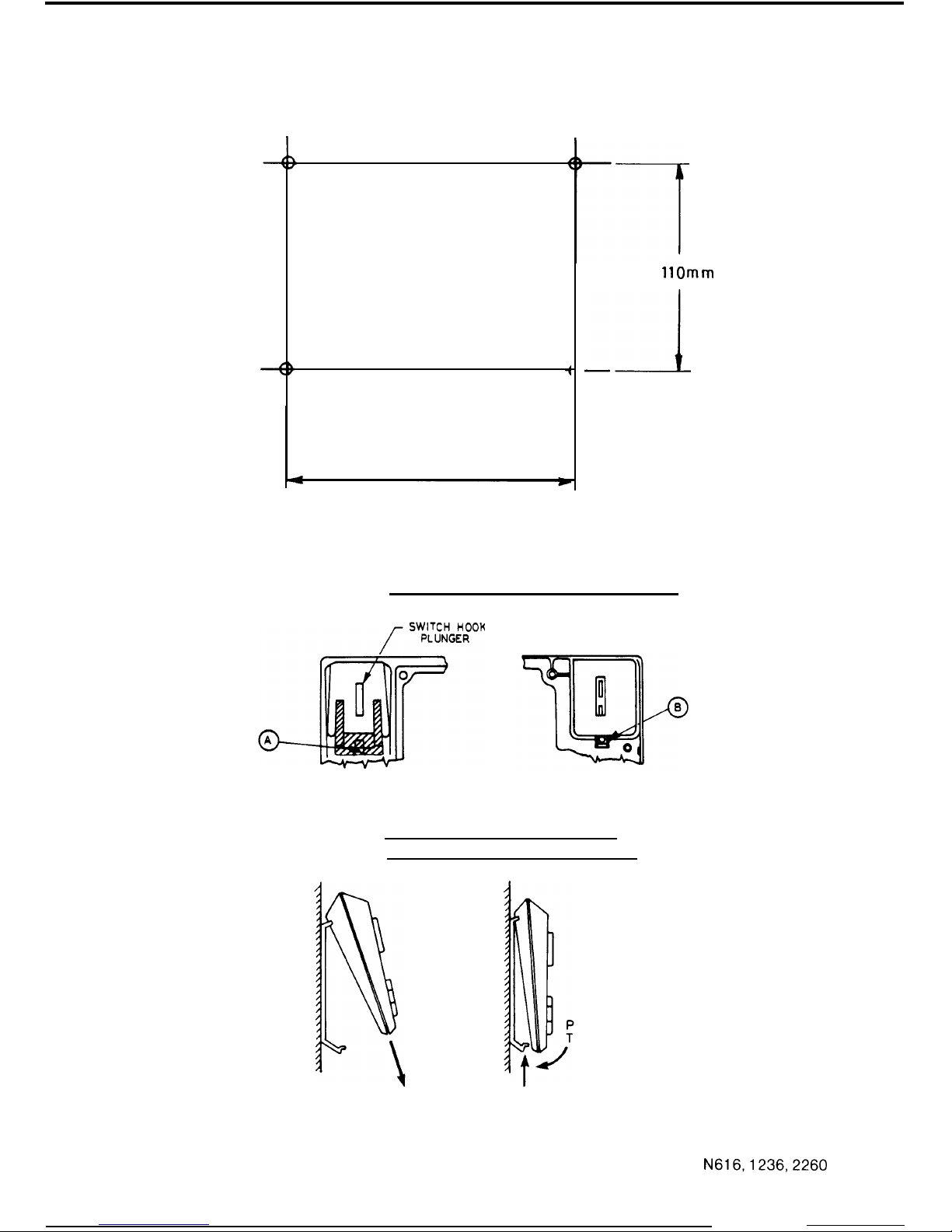
2.3.4
Stations
120mm
1lOmm
FIGURE 38 WALL MOUNTING FOR STATIONS
HOW TO INSTALL THE HANDSET HANGER
HOW TO PUT THE STATION ON TO
THE WALL MOUNTING BRACKET
RESS AGAINST
HE WALL
PULL DOWN
PUSH UP
FIGURE 39 WALL MOUNTING BRACKET INSTALLATION
N616,1236,2260
61
ISSUE 1
Page 65
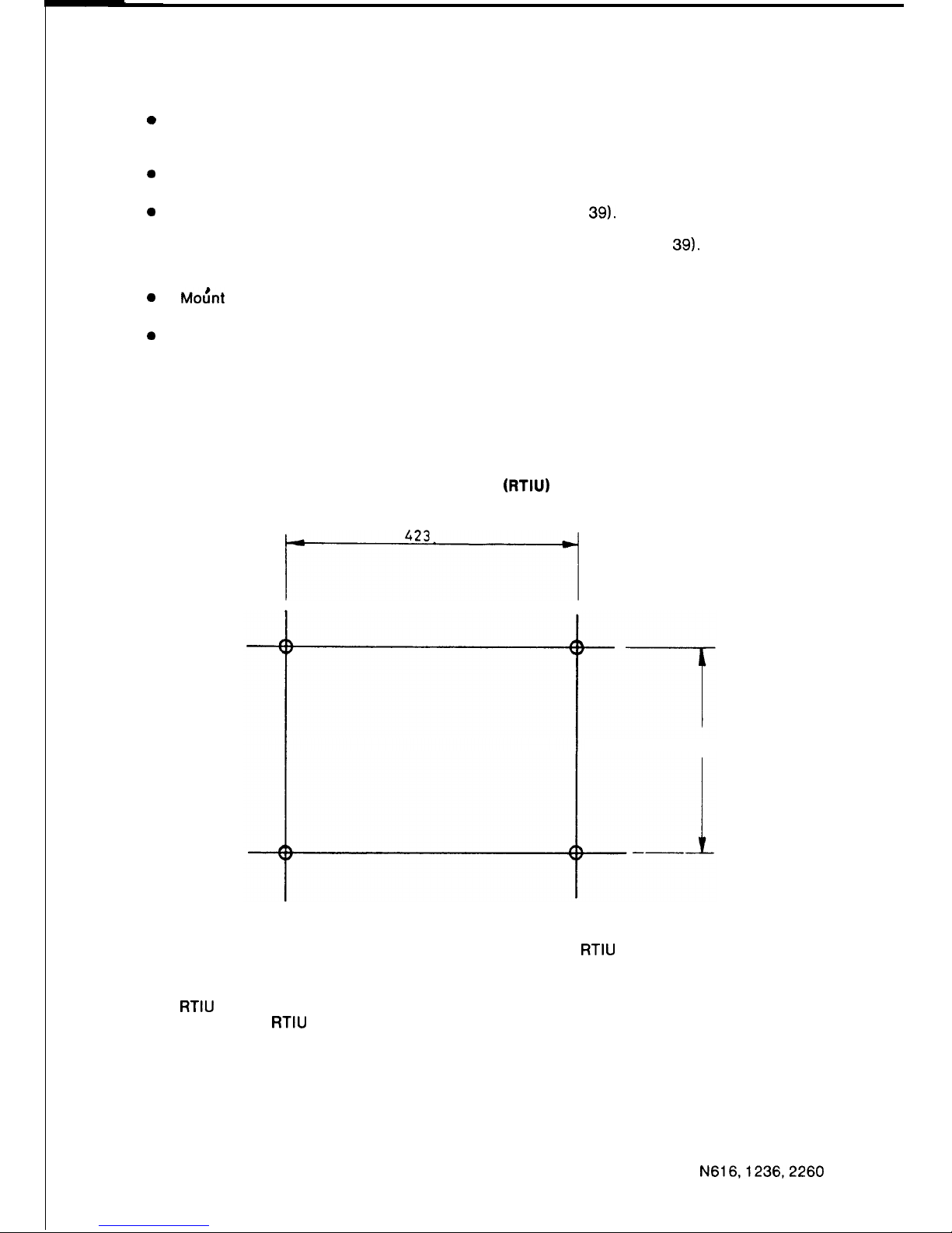
In order to mount the station on a wall, a Wall Mounting Bracket is required.
0
Mount the bracket on the wall by means of the four screws which are supplied with the
bracket. The bracket is located so that the edge with the two retaining tabs is at the top.
Hole centres are shown in figure 38.
0
0
0
0
Next, remove the front panel of the station with a screw driver, loosen the screws and
remove the case moulding from the base moulding.
Insert the hanger into the square hole (Point A in figure 39). This hole is located in the
recess on the top moulding used for the receiver of the handset. Fasten the metal retainer
from inside the housing using the screw provided (Point B in Figure 39). After fixing the
handset hanger to the top moulding, reassemble the top moulding and the base moulding,
tighten the screws and replace the front plate.
Mou’nt the telephone plug and socket on the wall in the centre of the wall mounting bracket.
The line cord should be gathered together and placed inside the wall-mounting bracket.
Now clip the station on to the wall-mounting bracket as shown in figure 39. This is done by
fixing the upper portion of the bracket into the two square holes located in the base plate of
the station. Then, push the station base towards the bracket until it clips into the lower
portion of the bracket.
2.3.5
Powerfail Bell
--
Remove the cover of the bell by unscrewing the Phillips head screw in the middle of the cover.
Screw the bell into place using the 3 holes located on the base, then replace the cover.
2.3.6 Remote Extension and Tie Line Interface Unit (RTIU)
*
FIGURE 40 WALL MOUNTING FOR THE
RTIU
150
The
RTIU
is located on the wall, normally adjacent to the main equipment. The mounting
procedure for the
RTIU
is the same as the mounting for the main equipment and power supply,
except the hole centres are different, refer to figure 40.
62
N616,1236,2260
ISSUE 1
Page 66
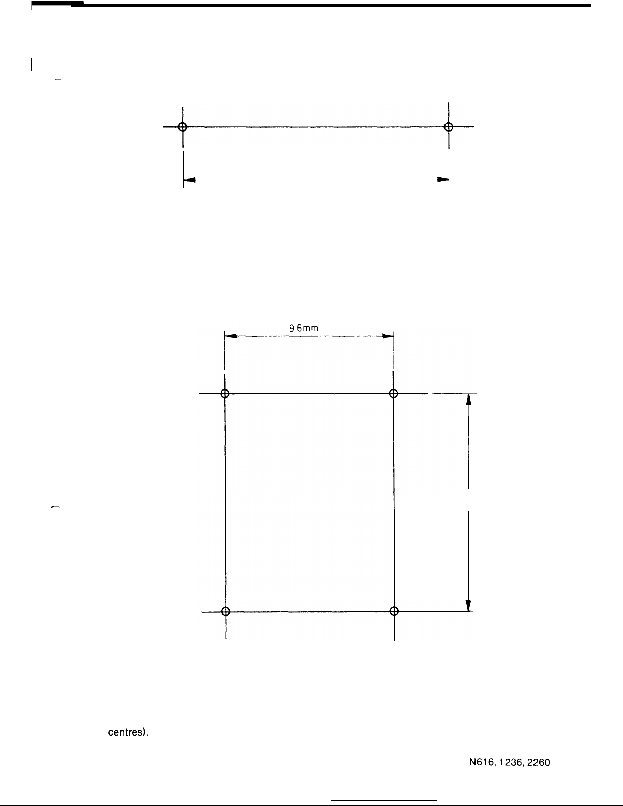
I
2.3.7 Call Metering Unit
-
4
24
Omm
w
FIGURE 41 WALL MOUNTING FOR CALL METERING UNIT
The unit is fixed to the wall adjacent to the system distributing frame. Remove the cover by
loosening the four retaining screws. Screw the base to the wall. Replace the cover after
terminating the exchange lines on the terminal block, refer to figure 41.
2.3.6
Ring Generator Unit
125mm
FIGURE 42 WALL MOUNTING FOR RING GENERATOR UNIT
The unit is fixed to the wall adjacent to the system distributing frame. Remove the cover by
loosening the four retaining screws. Screw the base to the wall (refer to figure 42 for hole
centres).
Replace the cover after terminating the wiring on the terminal block.
63
N616,1236,2260
ISSUE 1
Page 67
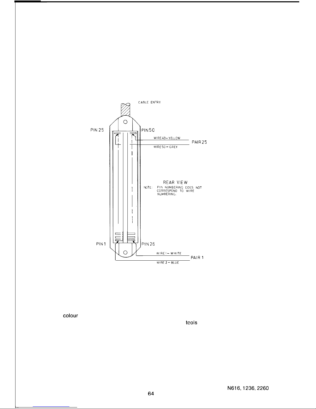
2.4 CABLING AND TERMINATING METHODS
2.4.1
General
Stations and other ancillary equipment will normally be cabled direct to the S.D.F. The main
equipment is connected to the S.D.F. via cables terminated, at the main equipment end, on 50
pin AMP Champ connectors.
Twisted two-pair cabling must be used when installing these systems. FLAT UNDER CARPET
CABLE MUST NOT BE USED.
2.4.2
AMP Champ Connectors
J@L
CABLE ENTRY
PIN 25
=1
PIN 1
F
r
I
I
I
I
‘IN 50
WIRE 43 - YELLOW
WIRE 50 - GREY
PAIR 25
REAR VIEW
NOTE:
PIN NUMBERING DOES NOT
CORRESPOND
TO
WIRE
NUMRERING.
‘IN 26
WIRE1 - WHITE
PAIR 1
WIRE 2 - BLUE
FIGURE 43 AMP CHAMP CONNECTOR -CABLE TERMINATION
Cables should be terminated in the following order, pair one located on pins number 1 and 26,
with the
colour
on pin 1 and the mate on pin 26. Note the cable entry shown in figure 43.
To avoid damaging the conductors, the correct terminating
tcols
must be used. Brackets are
provided with the main equipment to retain the AMP Champ connectors in position on the main
equipment.
64
N616,1236,2260
ISSUE 1
Page 68
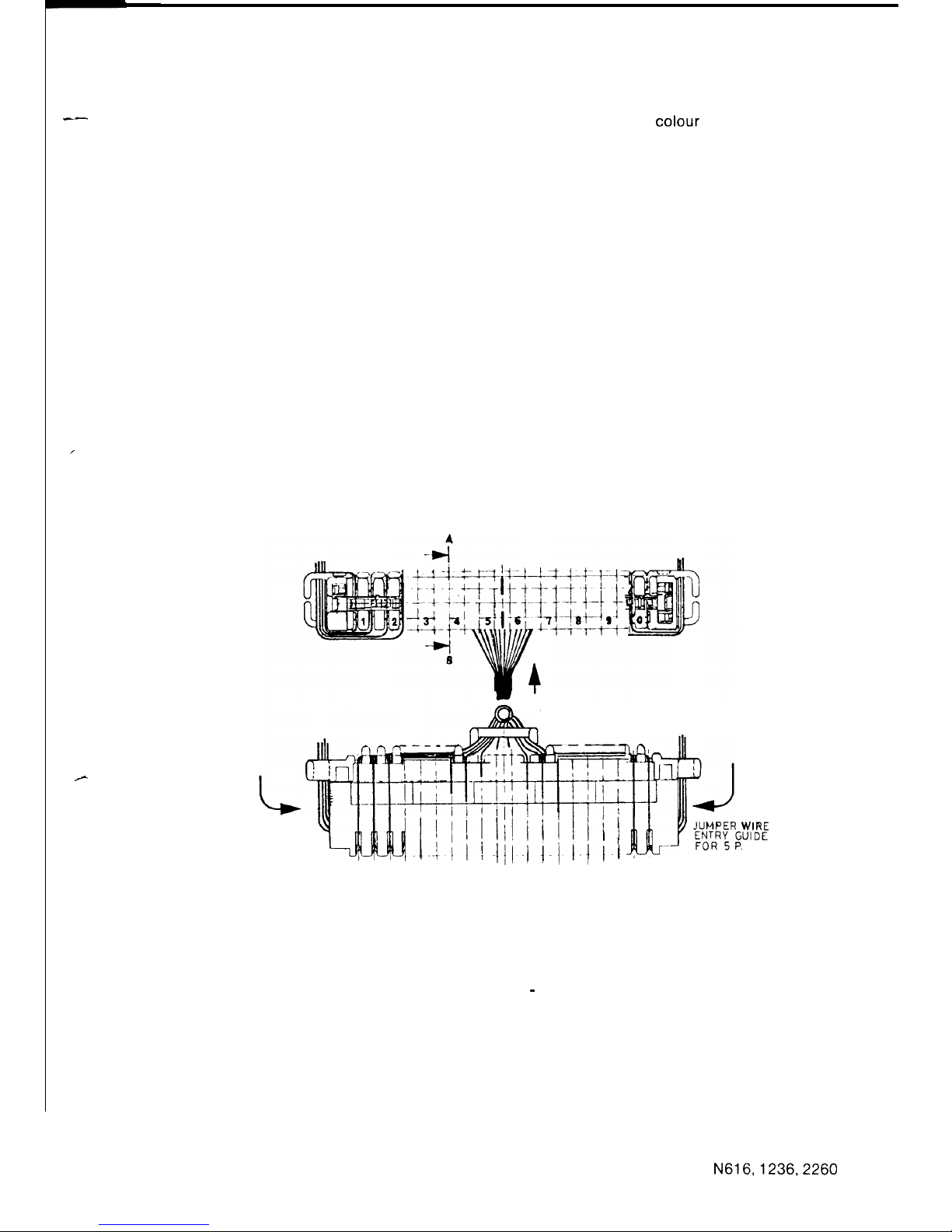
--
I
.--
2.4.3
S.D.F. Cabling
The cables from the main equipment are terminated at the S.D.F. in
colour
code sequence
commencing from the bottom row of Block A, Refer to figure 37.
Wire designations for each system are listed in tables 5, 6 and 7. Cabling from the main
equipment should be terminated in the top row of terminals of each module.
Cabling to the stations and optional equipment should be terminated in accordance with the
requirements listed on the SBS Sales Form. Note, the order for terminating exchange lines is
important when assigning audible signalling groups and the order for terminating stations is
important for station number allocation and assigning internal paging zones.
Station cabling should be terminated on the bottom row of terminals of each module. See
figures 36 and 37.
For ease of termination and to avoid damage to the conductors the correct terminating
technique and tool must be used.
2.4.3.1 Krone Terminal Module
CA BL E ENTRY GUIDE
FOR 10 PAIRS
JUMPER WIRE
ENTRY GUIDE
FOR 5 PAIRS
xc!
AIRS
FIGURE 44 KRONE TERMINAL MODULE - CABLE TERMINATION
The main equipment cabling is run in the trough formed by the backmount channel.
10 pair tails are then formed into a “goose neck” to allow future removal of the module, if
necessary. The tail is placed through the cable entry guide at the rear of the module and the
module is then locked in position on the backmount channel. The tail is then fanned out and the
wires placed in the slots, ready for termination to the top row of the module.
Station cabling is run as shown in figure 36 and 44 and terminated on the bottom row of the
module.
N616,1236,2260
65
ISSUE 1
Page 69
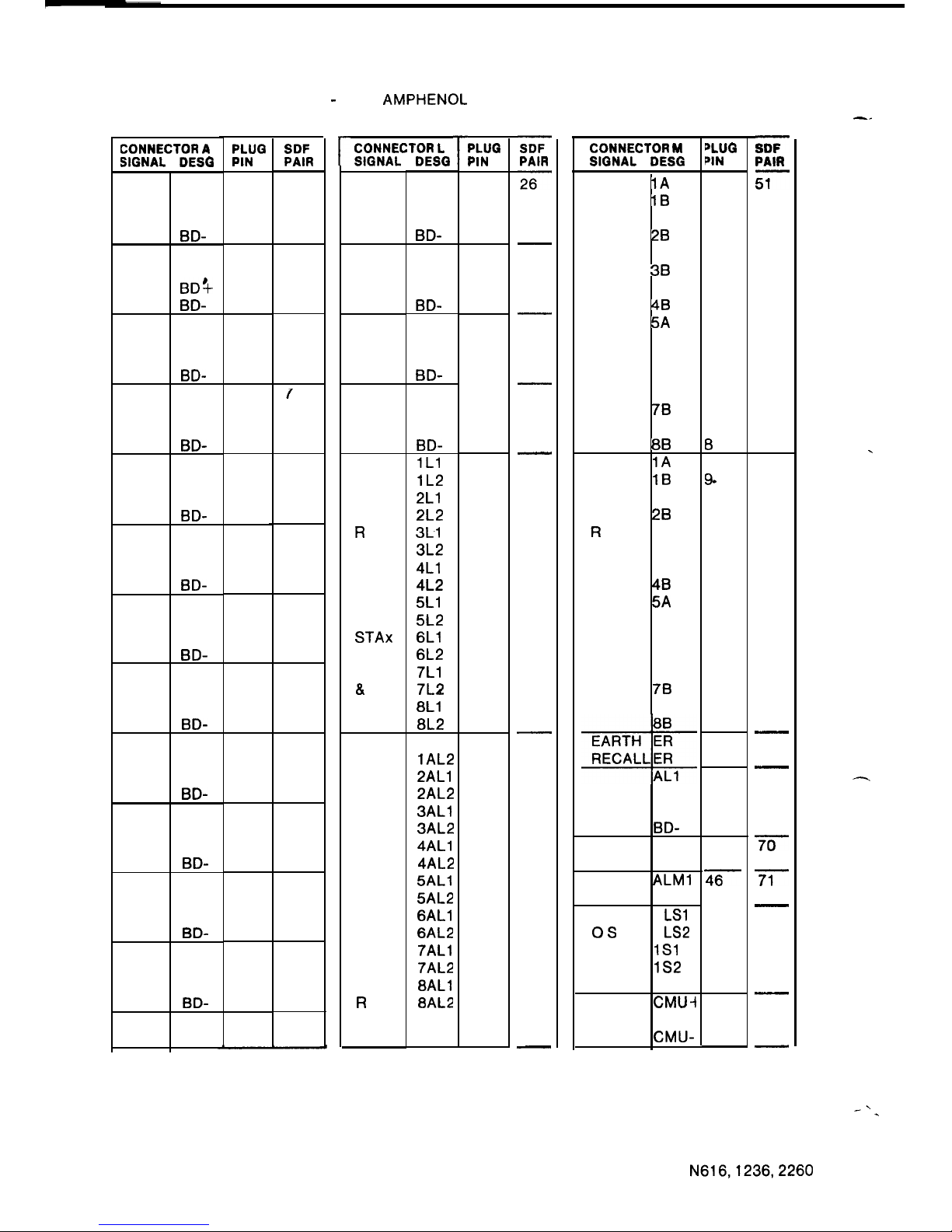
TABLE 5 - N 616 AMPHENOL CONNECTOR ASSIGNMENT
CONNECTOR
A
SIGNAL DESG
AL1
STA
AL2
20
BD+
BD-
AL1
STA
AL2
21
BDlt
BD-
AL1
STA
AL2
22
BD+
BD-
AL1
STA
AL2
23
BD+
BD-
AL1
STA
AL2
24
BD+
BD-
AL1
STA
AL2
25
BD+
BD-
AL1
STA
AL2
26 BD+
BD-
AL1
STA AL2
27 BD+
BD-
AL1
STA AL2
28
BD+
BD-
AL1
STA
AL2
29
BD+
BD-
AL1
STA
AL2
30 BD+
BD-
AL1
STA
AL2
31
BD+
BD-
PLUG SDF
PIN PAIR
26
1
27
2
28
3
29
4
30
5
31
6
32
7
33
8
34
9
35
10
36
11
37
12
38
13
39
14
40
15
41
16
42
17
43
18
44
19
45
20
46
21
47
22
48
23
49
24
50
25
1
2
3
4
5
6
7
8
9
10
11
12
13
14
15
16
17
18
19
20
21
22
23
24
25
r
CONNECTOR L
SIGNAL
STA
32
STA
33
STA
34
STA
35
PF
S
T
R
A
P
S
TO
STAx
AL1
a
AL2
PF
S
T
A
T
I
0
N
A
P
A
I
R
DESG
AL1
AL2
BD+
BD-
AL1
AL2
BD+
BD-
AL1
AL2
BD+
BD-
AL1
AL2
BD+
BD-
1Ll
lL2
2Ll
2L2
3Ll
3L2
4Ll
4L2
5Ll
5L2
6Ll
6L2
7Ll
7L2
8Ll
8L2
1
AL1
lAL2
2ALl
2AL2
3ALl
3AL2
4ALl
4AL2
5ALl
5AL2
6ALl
6AL2
7ALl
7AL2
8ALl
8AL2
r
PLUG
PIN
26
1
27
2
28
3
29
4
30
5
31
6
32
7
33
8
34
9
35
10
36
11
37
12
38
13
39
14
40
15
41
16
42
17
43
18
44
19
45
20
46
21
47
22
48
23
49
24
50
25
SDF
PAIR
26
27
28
29
30
31
32
33
34
35
3.6
37
38
39
40
41
42
43
44
45
46
47
48
49
50
CONNECTOR M
PLUG
SIGNAL
DESG
PIN
E
1A
X
1B
C
2A
H
28
A
3A
N
38
G
4A
E
48
5A
L
5B
I
6A
N
6B
E
7A
S
78
8A
88
P
1A
0
1B
W
2A
E
28
R
3A
F
3B
A
4A
I
48
L
5A
5B
B
6A
E
6B
L
7A
L
78
S
8A
DSS
AL2
36 BD+
BD-
BGM Ml
M2
ALARM
ALMl
ALM2
L
1
LSl
OS
1 LS2
UP
1Sl
DK
lS2
CMU
CMU-i
CMU-
26
1
27
2
28
3
29
4
30
5
31
6
32
7
33
8
34
9.
35
10
36
11
37
12
38
13
39
14
40
15
41
16
42
17
43
18
44
19
45
20
46
21
47
22
48
23
49
24
50
25
SDF
PAIR
iFi--
52
53
54
55
56
57
58
59
60
61
62
63
64
65
66
67
68
69
70
71
72
73
74
75
-_
.
-
-’
.
66
N616,1236,2260
ISSUE1
Page 70
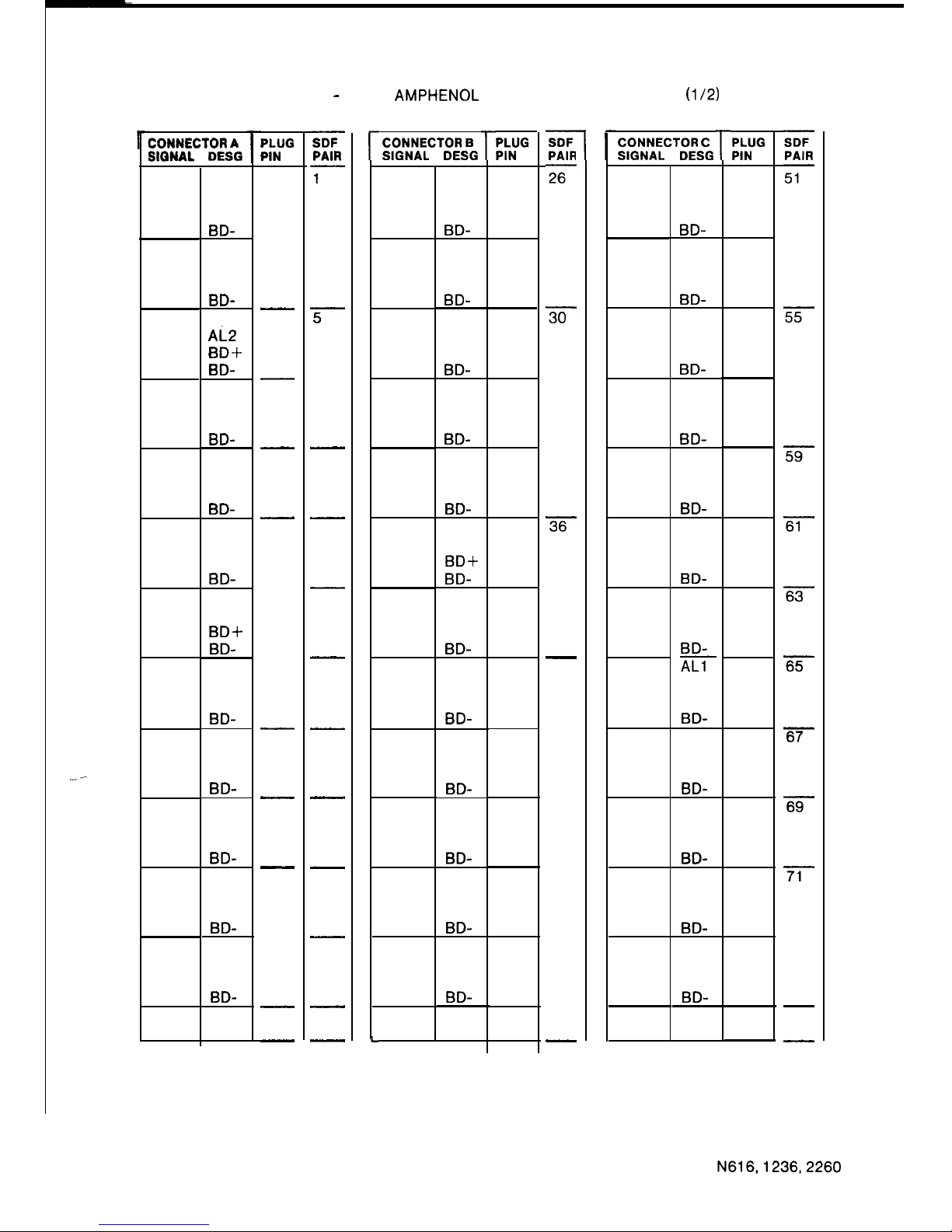
TABLE 6 - N 1236 AMPHENOL CONNECTOR ASSIGNMENT
(112)
.__-
CONNECTOR A
SIQNAL DESG
STA
20
STA
21
STA
22
STA
23
STA
24
STA
25
STA
26
STA
27
STA
28
STA
29
STA
30
STA
31
AL1
AL2
BD+
BD-
AL1
AL2
BD+
BD-
AL1
Ai
BD+
BD-
AL1
AL2
BD+
BD-
AL1
AL2
BD+
BD-
AL1
AL2
BD+
BD-
AL1
AL2
BD-t-
BD-
AL1
AL2
BD+
BD-
AL1
AL2
BD+
BD-
AL1
AL2
BD+
BD-
AL1
AL2
BD+
BD-
AL1
AL2
BD+
BD-
PLUG
PIN
26
1
27
2
28
3
29
4
30
5
31
6
32
7
33
8
34
9
35
10
36
11
37
12
38
13
39
14
40
15
41
16
42
17
43
18
44
19
45
20
46
21
47
22
48
23
49
24
50
25
SDF
PAIR
T---
2
3
4
5
6
7
8
9
10
11
12
13
14
15
16
17
18
19
20
21
22
23
24
25
r
L
CONNECTOR B
SIGNAL DESG
STA
32
STA
33
STA
34
STA
35
STA
36
STA
37
STA
38
STA
39
STA
40
STA
41
STA
42
STA
43
AL1
AL2
BD+
BD-
AL1
AL2
BD+
BD-
AL1
AL2
BD+
BD-
AL1
AL2
BD+
BD-
AL1
AL2
BD+
BD-
AL1
AL2
BD-t-
BD-
AL1
AL2
BD+
BD-
AL1
AL2
BD+
BD-
AL1
AL2
BD+
BD-
AL1
AL2
BD+
BD-
AL1
AL2
BD+
BD-
AL1
AL2
BD+
BD-
r
PLUG
PIN
26
1
27
2
28
3
29
4
30
5
31
6
32
7
33
8
34
9
35
10
36
11
37
12
38
13
39
14
40
15
41
16
42
17
43
18
44
19
45
20
46
21
47
22
48
23
49
24
50
25
SDF
PAIR
26
27
28
29
30
31
32
33
34
35
36
37
38
39
40
41
42
43
44
45
46
47
48
49
50
1
CONNECTOR C
SIGNAL
DESG
STA
44
STA
45
STA
46
STA
47
STA
48
STA
49
STA
50
STA
51
STA
52
STA
53
STA
54
STA
55
AL1
AL2
BD+
BD-
AL1
AL2
BD+
BD-
AL1
AL2
BD+
BD-
AL1
AL2
BD+
BD-
AL1
AL2
BD+
BD-
AL1
AL2
BD+
BD-
AL1
AL2
BD+
BD-
iiii-
AL2
BD+
BD-
AL1
AL2
BD+
BD-
AL1
AL2
BD+
BD-
AL1
AL2
BD+
BD-
AL1
AL2
BD+
BD-
r
PLUG
PIN
26
1
27
2
28
3
29
4
30
5
31
6
32
7
33
8
34
9
35
10
36
11
37
12
38
13
39
14
40
15
41
16
42
17
43
18
44
19
45
20
46
21
47
22
48
23
49
24
50
25
SDF
PAIR
51
52
53
54
55
56
57
58
59
60
61
62
63
64
65
66
67
68
69
70
71
72
73
74
75
67
N616,1236,2260
ISSUE 1
Page 71
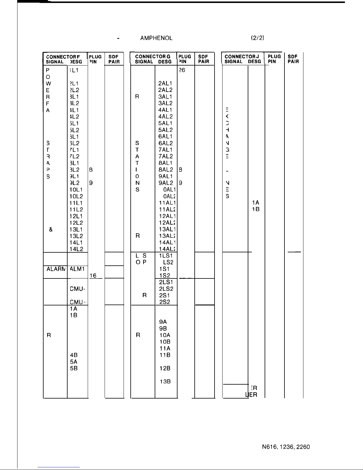
TABLE 6 - N 1236 AMPHENOL CONNECTOR ASSIGNMENT
(212)
ZONNECTOR
F
TO
STA
xx
AL1
&
AL2
BGM
ALARtv
CMU
P
0
W
E
R
F
A
I
L
B
E
L
L
IESG
IL1
IL2
!Ll
!L2
3Ll
3L2
IL1
IL2
jL1
5L2
jL1
3L2
7Ll
IL2
3Ll
3L2
3Ll
3L2
I
OLl
I OL2
11Ll
llL2
12Ll
12L2
13Ll
13L2
14Ll
14L2
Ml
M2
ALMl
ALM2
CMUCMU-
1A
1B
2A
2B
3A
3B
4A
48
5A
5B
6A
6B
7A
7B
‘LUG
‘IN
26
1
27
2
28
3
29
4
30
5
31
6
32
7
33
0
34
9
35
10
36
11
37
12
38
13
39
14
40
15
41
EL
42
17
43
18
44
19
45
20
46
21
47
22
48
23
49
24
50
25
SDF
PAIR
76
77
78
79
80
81
82
83
84
85
86
87
88
89
90
91
92
93
94
95
96
97
98
99
100
r
CONNECTOR
G
r;
SIGNAL
DESG
P
0
W
E
R
F
A
I
L
A
P
A
I
R
LS
OP
UE
DA
K
E
R
S
P
0
W
E
R
F
A
I
L
B
E
L
L
1 AL1
1 AL2
2ALl
2AL2
3ALl
3AL2
4ALl
4AL2
5ALl
5AL2
6ALl
6AL2
7ALl
7AL2
8ALl
8AL2
9ALl
9AL2
1 OALl
1 OAL;
11ALl
11AL;
12ALl
12AL:
13ALl
13AL:
14ALl
14AL:
lLS1
1 LS2
1Sl
lS2
2LSl
2LS2
2Sl
2s2
8A
8B
9A
9B
10A
IOB
11A
11B
12A
128
13A
138
14A
14B
‘LUG
SDF
‘IN
PAIR
26
1
27
2
28
3
29
4
30
5
31
6
32
7
33
0
34
9
35
10
36
11
37
12
38
13
39
14
40
15
41
16
42
17
43
18
44
19
45
20
46
21
47
22
48
23
49
24
50
25
101
102
103
104
105
106
107
108
109
110
111
112
113
114
115
116
117
118
119
120
121
122
123
124
125
r
(
I
:ONNECTOR J
ilGNAL
DESG
r
I
I
EARTH
RECAL
A
B
A
B
A
B
A
B
A
B
A
B
A
B
A
B
A
B
OA
OB
1A
1B
2A
2B
3A
3B
4A
4B
iR
iR
‘LUG
‘IN
26
1
27
2
28
3
29
4
30
5
31
6
32
7
33
8
34
9
35
10
36
11
37
12
38
13
39
14
40
15
41
16
42
17
43
18
44
19
45
20
46
21
47
22
48
23
49
24
50
25
SDF
PAIR
126
127
128
129
130
131
132
133
134
135
136
137
138
139
140
141
142
143
144
145
146
147
148
149
150
68
N616,1236,2260
ISSUE 1
Page 72
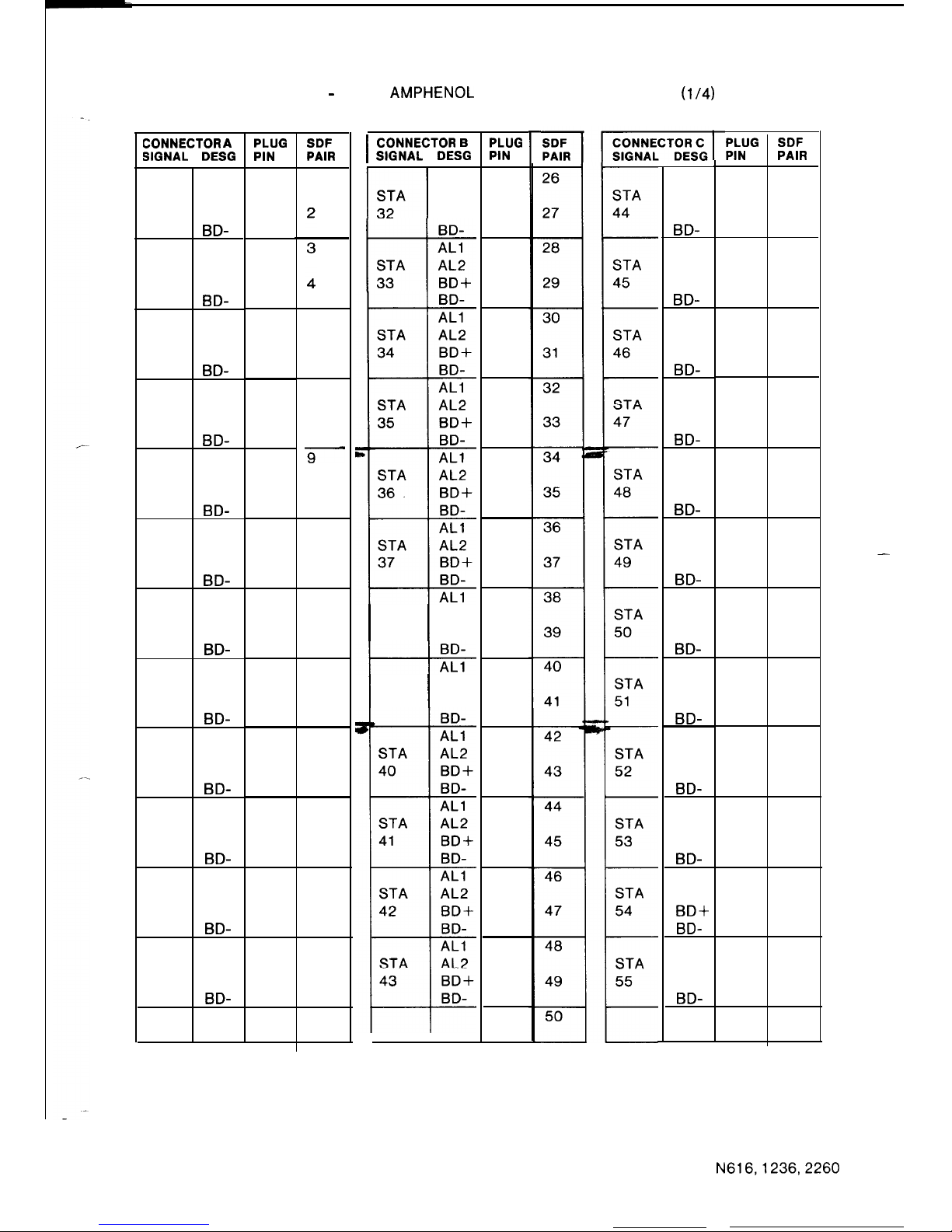
TABLE 7 - N 2260 AMPHENOL CONNECTOR ASSIGNMENT
(l/4)
CONNECTOR
A
SIGNAL DESG
AL1
STA
AL2
20
BD+
BD-
AL1
STA
AL2
21
BD+
BD-
AL1
STA
AL2
22
BD+
BD-
AL1
STA
AL2
23
BD+
BD-
AL1
STA
AL2
24
BD+
BD-
AL1
STA
AL2
25
BD+
BD-
AL1
STA
AL2
26 BD+
BD-
AL1
STA
AL2
27
BD+
BD-
AL1
STA AL2
28
BD+
BD-
AL1
STA
AL2
29 BD+
BD-
AL1
STA AL2
30 BD+
BD-
AL1
STA
AL2
31
BD+
BD-
PLUG
PIN
26
1
27
2
28
3
29
4
30
5
31
6
32
7
33
8
34
9
35
10
36
11
37
12
38
13
39
14
40
15
41
16
42
17
43
18
44
19
45
20
46
21
47
22
48
23
49
24
50
25
SDF
PAIR
1
5
6
7
8
9
10
11
12
13
14
15
16
17
18
19
20
21
22
23
24
25
I
CONNECTOR
B
SIGNAL
DESG
AL1
AL2
BD+
BD-
AL1
H-
STA
AL2
33
BD+
STA
I
I
AL2
38
BD+
STA
I
I
AL2
39 BD+
PLUG
PIN
26
1
27
2
28
3
29
4
30
5
31
6
32
7
33
8
34
9
35
10
36
11
37
12
38
13
39
14
40
15
41
16
42
17
43
18
44
19
45
20
46
21
47
22
48
23
49
24
50
25
r
r
AL1
AL2
BD+
BD-
AL1
AL2
BD+
BD-
AL1
AL2
BD+
BD-
AL1
AL2
BD+
BD-
AL1
AL2
BD+
BD-
AL1
AL2
BD+
BD-
AL1
AL2
BD+
BD-
AL1
AL2
BD+
BD-
AL1
AL2
BD+
BD-
AL1
AL2
BD+
BD-
AL1
AL2
BDS
BD-
AL1
AL2
BD+
BD-
PLUG SDF
PIN PAIR
26 51
1
27 52
2
28 53
3
29 54
4
30 55
5
31 56
6
32 57
7
33 58
8
34 59
9
35 60
10
36 61
11
37 62
12
38 63
13
39 64
14
40 65
15
41 66
16
42 67
17
43 68
18
44 69
19
45 70
20
46 71
21
47 72
22
48 73
23
49 74
24
50 75
25
-
69
N616,1236,2260
ISSUE 1
Page 73
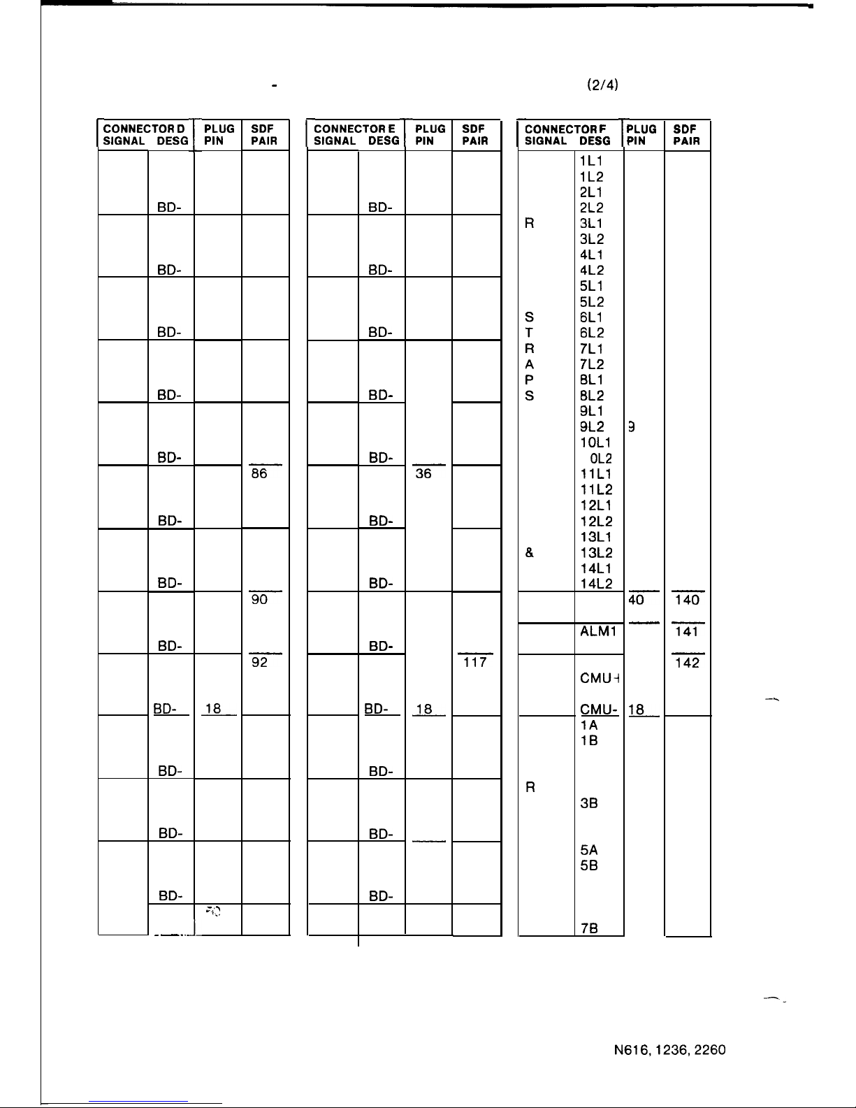
TABLE 7 - N 2260AMPHENOL CONNECTOR ASSIGNMENT
(2/4)
c
CONNECTOR
D
SIGNAL DESG
T-
STA
56
STA
57
STA
58
STA
59
STA
60
STA
61
STA
62
STA
63
STA
64
STA
65
STA
66
STA
67
--
AL1
AL2
BD+
BD-
AL1
AL2
BD+
BD-
AL1
AL2
BD+
BD-
AL1
AL2
BD+
BD-
AL1
AL2
BD+
BD-
AL1
AL2
BD+
BD-
AL1
AL2
BD+
BD-
AL1
AL2
BD+
BD-
AL1
AL2
BD+
BD-
AL1
AL2
BD+
BD-
AL1
AL2
BD+
BD-
AL1
AL2
BD+
BD-
- -_..
L
l-
PLUG
PIN
26
1
27
2
28
3
29
4
30
5
31
6
32
7
33
8
34
9
35
10
36
11
37
12
38
13
39
14
40
15
41
16
42
17
43
18
44
19
45
20
46
21
47
22
48
23
49
24
;
‘,
,
)il
25
SDF
PAIR
76
77
78
79
80
81
82
83
84
85
86
87
88
89
90
91
92
93
94
95
96
97
98
99
100
c;
CONNECTOR
E
SIGNAL DESG
STA
68
STA
69
STA
70
STA
71
STA
72
STA
73
STA
74
STA
75
STA
76
STA
77
STA
78
STA
79
AL1
AL2
BD+
BD-
AL1
AL2
BD+
BD-
AL1
AL2
BD+
BD-
AL1
AL2
BD+
BD-
AL1
AL2
BD+
BD-
AL1
AL2
BD+
BD-
AL1
AL2
BD+
BD-
AL1
AL2
BD+
BD-
AL1
AL2
BD+
BD-
AL1
AL2
BD+
BD-
AL1
AL2
BD+
BD-
AL1
AL2
BD+
BD-
r
PLUG
PIN
26
1
27
2
28
3
29
4
30
5
31
6
32
7
33
8
34
9
35
10
36
11
37
12
38
13
39
14
40
15
41
16
42
17
43
18
44
19
45
20
46
21
47
22
48
23
49
24
50
25
SDF
PAIR
101
102
103
104
105
106
107
108
109
110
111
112
113
114
115
116
117
118
119
120
121
122
123
124
125
CONNECTOR
F
SIGNAL DESG
P
0
W
E
R
F
A
I
L
TO
STA
xx
AL1
8.
AL2
BGM
ALARM
1Ll
lL2
2Ll
2L2
3Ll
3L2
4Ll
4L2
5Ll
5L2
6Ll
6L2
7Ll
7L2
6Ll
BL2
9Ll
9L2
1OLl
1
OL2
llL1
llL2
12Ll
12L2
13Ll
13L2
14Ll
14L2
Ml
M2
ALMl
ALM2
CMU CMU-i
P
0
W
E
R
F
A
I
L
B
E
L
L
CMU1A
1B
2A
2B
3A
38
4A
4B
5A
5B
6A
6B
7A
78
r
I
I
‘LUG
DIN
26
1
27
2
28
3
29
4
30
5
31
6
32
7
33
9
34
3
35
10
36
11
37
12
38
13
39
14
40
15
41
16
42
17
43
18
44
19
45
20
46
21
47
22
48
23
49
24
50
25
SDF
PAIR
126
127
128
129
130
131
132
133
134
135
136
137
138
139
ixTii142
143
144
145
146
147
148
149
150
-.
70
-_
N616,1236,2260
ISSUE 1
Page 74
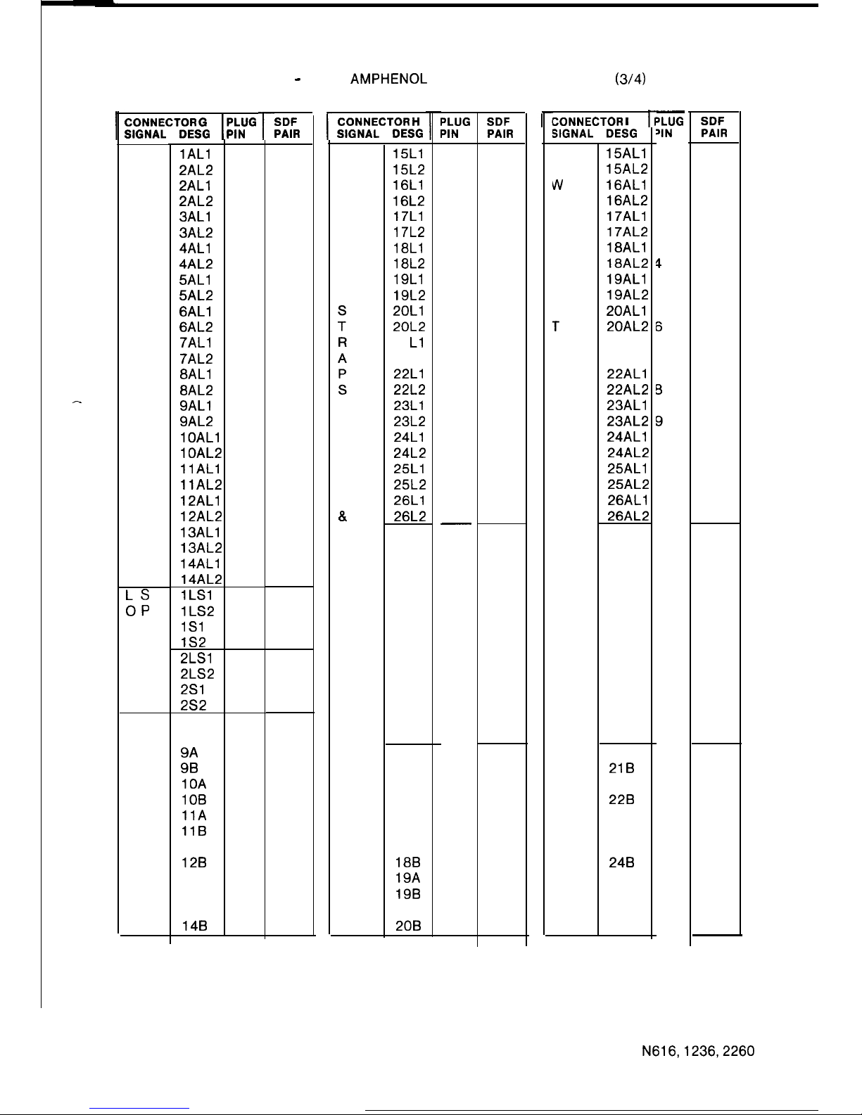
TABLE 7 - N 2260 AMPHENOL CONNECTOR ASSIGNMENT
(3/4)
-
CONNECTOR
GIPLUG
SIGNAL DESG PIN
P
0
W
E
R
F
A
I
L
S
T
A
T
I
0
N
S
A
P
A
I’
R
LS
OP
UE
DA
K
E
R
S
P
0
W
E
R
F
A
I
L
B
E
L
L
lAL1
26
2AL2 1
2ALl
27
2AL2 2
3ALl
28
3AL2
3
4ALl
29
4AL2
4
5ALl
30
5AL2
5
6ALl
31
6AL2
6
7ALl
32
7AL2 7
8ALl
33
8AL2
8
9ALl
34
9AL2
9
lOAL
35
lOAL
10
llAL1
36
llAL2
11
12ALl
37
12AL2 12
13ALl
38
13AL2 13
14ALl
39
14AL2 14
1LSl
40
lLS2
15
1Sl
41
lS2
16
2LSl
42
2LS2 17
2Sl
43
2S2 18
8A 44
8B 19
9A 45
9B 20
10A 46
10B 21
11A 47
11B 22
12A 48
128
23
13A 49
13B 24
14A 50
148
25
r
SDF
PAIR
151
152
153
154
155
156
157
158
159
160
161
162
163
164
165
166
167
168
169
170
171
172
173
174
175
r
CONNECTOR H
SIGNAL
DESG
P
0
W
E
R
F
A
I
L
TO
STA
xx
AL1
8.
AL2
P
0
W
E
R
F
A
I
L
B
E
L
L
15Ll
15L2
16Ll
16L2
17Ll
17L2
18Ll
18L2
19Ll
19L2
2OLl
2OL2
21
Ll
21 L2
22Ll
22L2
23Ll
23L2
24Ll
24L2
25Ll
25L2
26Ll
26L2
15A
15B
16A
16B
17A
17B
18A
188
19A
19B
20A
208
PLUG
PIN
26
1
27
2
28
3
29
4
30
5
31
6
32
7
33
8
34
9
35
10
36
11
37
12
38
13
39
14
40
15
41
16
42
17
43
18
44
19
45
20
46
21
47
22
48
23
49
24
50
25
SDF
PAIR
176
177
178
179
180
181
182
183
184
185
186
187
188
189
190
191
192
193
194
195
196
197
198
199
200
CONNECTOR
I
SIGNAL DESG
P
3
Iv
E
R
F
A
I
L
S
T
A
T
I
0
N
S
A
P
A
I
R
P
0
W
E
R
F
A
I
L
B
E
L
L
15ALl
15AL2
16ALl
16AL2
17ALl
17AL2
18ALl
18AL2
19ALl
19AL2
20ALl
20AL2
21 AL1
21 AL2
22ALl
22AL2
23ALl
23AL2
24ALl
24AL2
25ALl
25AL2
26ALl
26AL2
21A
218
22A
228
23A
23B
24A
248
25A
25B
26A
26B
L
‘LUG
‘IN
26
1
27
2
28
3
29
4
30
5
31
6
32
7
33
B
34
9
35
10
36
11
37
12
38
13
39
14
40
15
41
16
42
17
43
18
44
19
45
20
46
21
47
22
48
23
49
24
50
25
SDF
PAIR
201
202
203
204
205
206
207
208
209
210
211
212
213
214
215
216
217
218
219
220
221
222
223
224
225
N616,1236,2260
71
ISSUE 1
Page 75
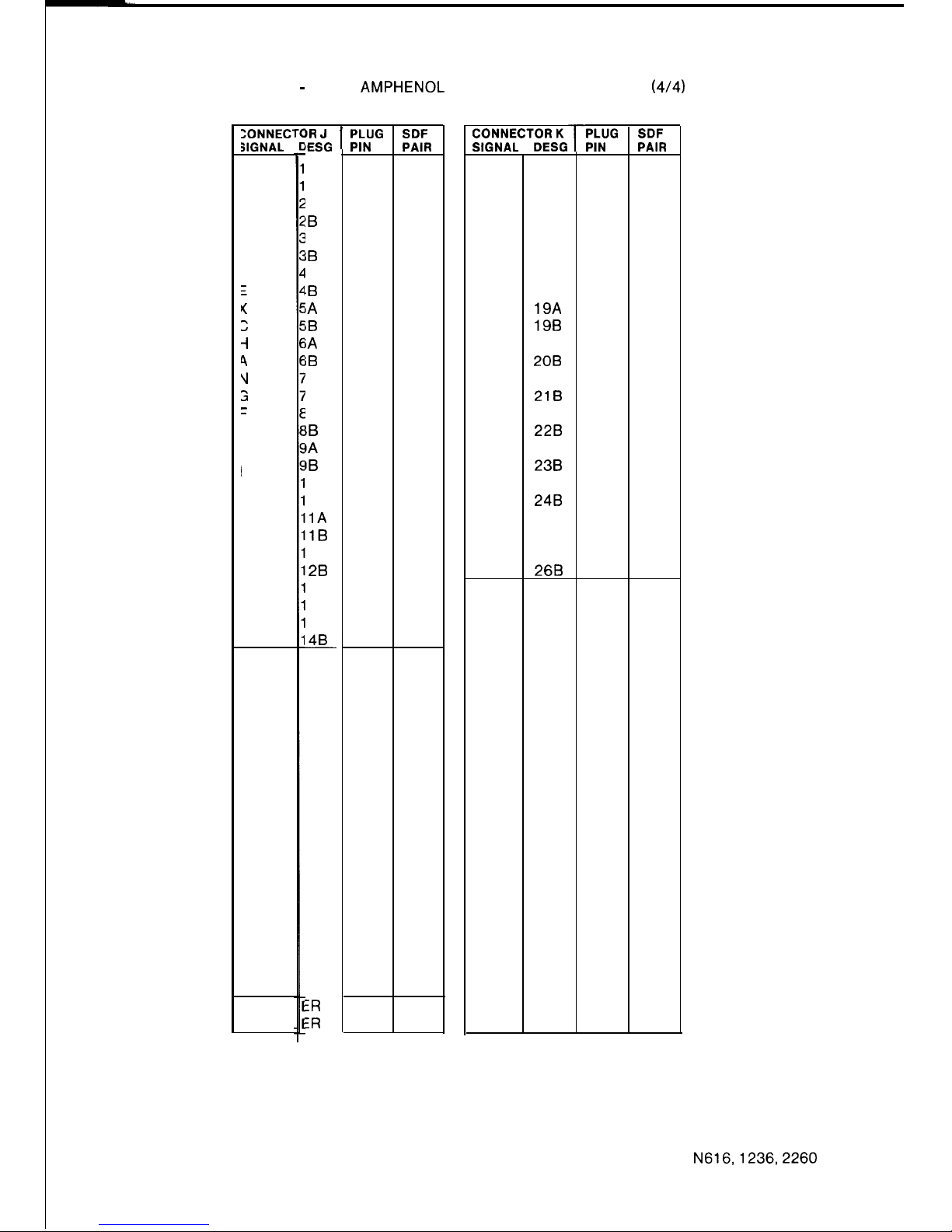
TABLE 7 - N 2260 AMPHENOL CONNECTOR ASSIGNMENT
(414)
ZONNECSIGNAL
1
;
2
-I
4
v
3
1
L
I
N
E
S
EARTH
RECALL
BR J
lESG
A
B
!A
!B
IA
IB
.A
.B
iA
iB
iA
iB
‘A
‘B
IA
IB
IA
IB
OA
OB
1A
1B
2A
28
3A
3B
4A
48
IR
:R
I
PLUG
PIN
26
1
27
2
28
3
29
4
30
5
31
6
32
7
33
8
34
9
35
10
36
11
37
12
38
13
39
14
40
15
41
16
42
17
43
18
44
19
45
20
46
21
47
22
48
23
49
24
50
25
SDF
PAIR
226
227
228
229
230
231
232
233
234
235
236
237
238
239
240
241
242
243
244
245
246
247
248
249
250
r
SIGNAL
T
E
X
C
H
A
N
G
E
L
I
N
E
S
15A
15B
16A
16B
17A
17B
18A
18B
19A
19B
20A
208
21A
218
22A
228
23A
238
24A
248
25A
25B
26A
268
PLUG
PIN
26
1
27
2
28
3
29
4
30
5
31
6
32
7
33
8
34
9
35
10
36
11
37
12
38
13
39
14
40
15
41
16
42
17
43
18
44
19
45
20
46
21
47
22
48
23
49
24
50
25
SDF
PAIR
251
252
253
254
255
256
257
258
259
260
261
262
263
264
265
266
267
268
269
270
271
272
273
274
275
72
N616,1236,2260
ISSUE 1
Page 76
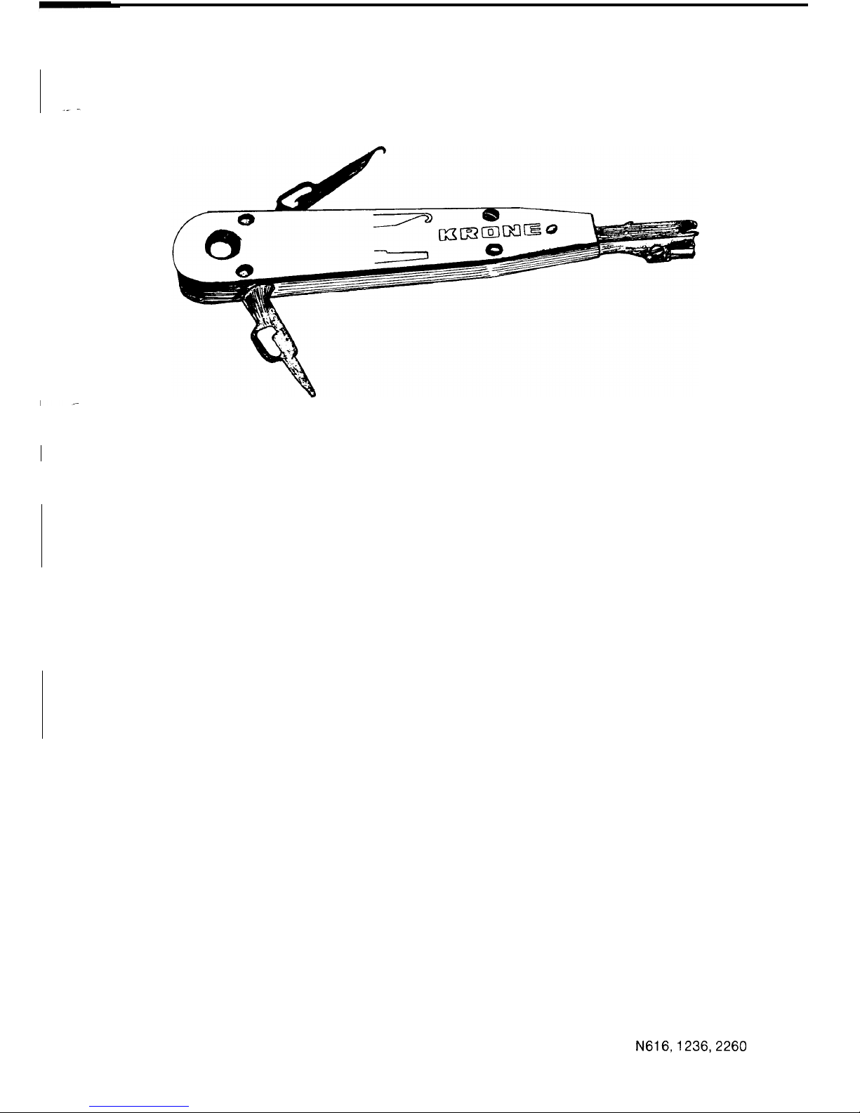
2.4.3.2 Krone Terminating Tool
I
FIGURE 45 KRONE TERMINATING TOOL
The terminating tool shown in figure 45, is a spring loaded percussion device incorporating
scissor action wire cutters. Termination and wire cutting are achieved by a single motion.
Physically the tool can only be inserted one way, thus preventing the installer cutting the wrong
side of the wire.
The “hook end” attachment is used for disconnection of the wire and for removing disconnect
plugs.
The “blade end” attachment is used to remove the module from the backmount channel. The
blade is inserted into the slot, at the ends of the module, to unseat the locking tabs on each side
of the module from the backmount channel. The module can then be pulled off the backmount
channel.
2.4.4
Lightning Protection
Lightning protection must be provided. The method of protection is comprehensively explained
in Headquarters SBS Engineering Branch Information Document Number T32, “Lightning
Protection for Commander N Series Business Systems”.
73
N616,1236,2260
ISSUE 1
Page 77
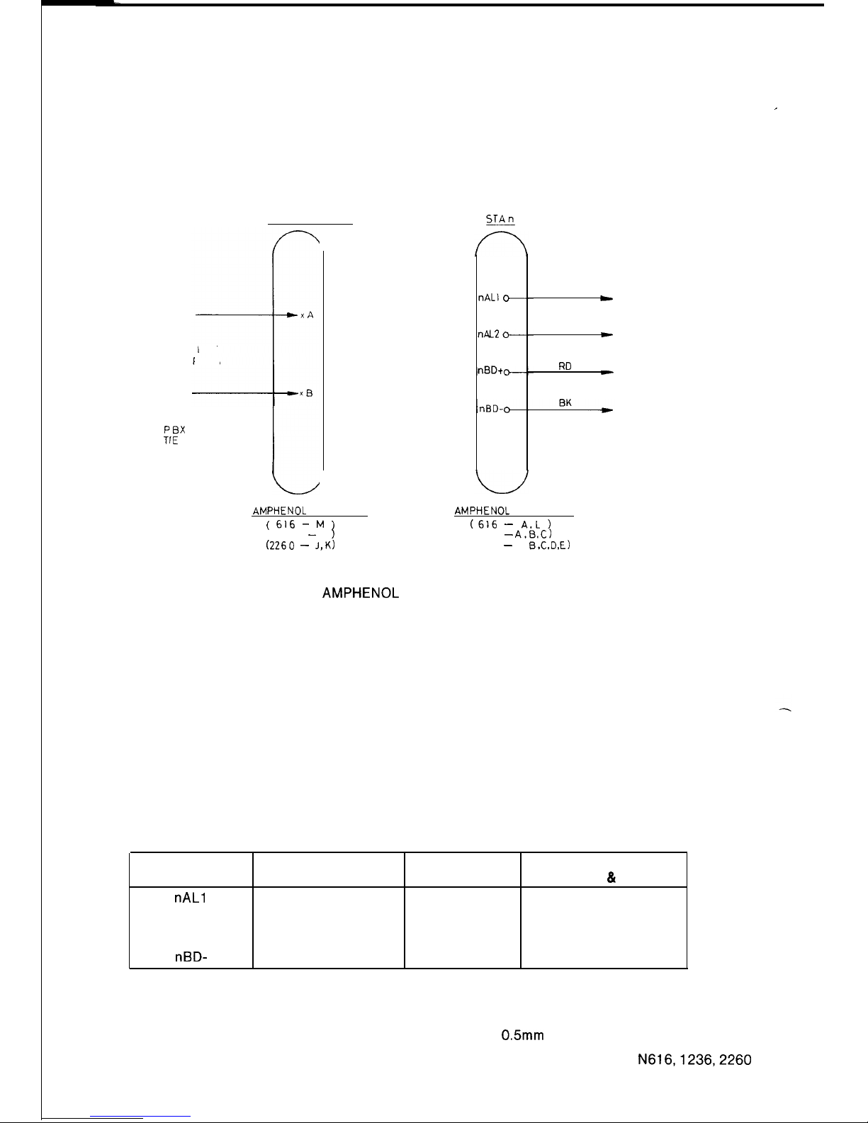
2.4.5
Exchange Lines
The exchange lines are terminated on the S.D.F. If a call metering unit is used, the exchange
lines must be terminated on the CMU before being terminated on the S.D.F.
The order in which the exchange lines are terminated at the main equipment is important when
assigning audible signalling groups.
Refer to figure 46, x represents the exchange line number.
_
__
EXCHANGE LINES
STAn
LINE
PAIRS
EXCHANGE LINEEXCHANGE LINE
PBXPBX
TrE
LINES
TrE
LINES
L
WT
c
BL
t
TO STATIONS
VIA SDF
RD
C
AMPHENOL
CONNECTOR
AMPHENOL
CONNECTOR
( 616 -
M
)
(616 - A.L )
(1236 - J
)
(1236 -
A.6.C)
(2260 - J,K)
(2260 - A,
B.C,D,E)
FIGURE 46 AMPHENOL CONNECTOR TERMINATIONS
FOR STANDARD STATIONS
2.4.6 Earth Recall
When the system is connected to a PBX and the recall facility is required, the PBX earth must be
connected to the ER connections via the S.D.F.
2.4.7
Stations and DSS Console
When cabling from the main equipment to the stations take care that the pairs are correctly
terminated and the polarity of the pair is correct. Fuses in the main equipment will blow or the
equipment will not operate if the system is not correctly cabled. The order in which stations are
connected and the station number are important when assigning paging zones.
Refer to figure 46, n represents station number
TABLE 6 STATION CABLING
WIRE 603 PLUG/61 0 WIRE COLOUR DESIGNATION
DESIGNATION SOCKET STATION %I DSS
nAL1
2
WT White
LWT
nAL2
6
BL Blue
LBL
nBD+
1
RD Red LRD
nBD-
5
BK Black LBK
Provision must be made to allow for connection of both a DSS station and a DSS console for
programming and testing. If the customer has not requested a DSS console, the DSS station and
DSS console point must be cabled and located near the ME/SDF.
When cabling for stations the following limitations apply for 0.5mm twisted 2 pair cable.
N616,1236,2260
74
ISSUE 1
Page 78
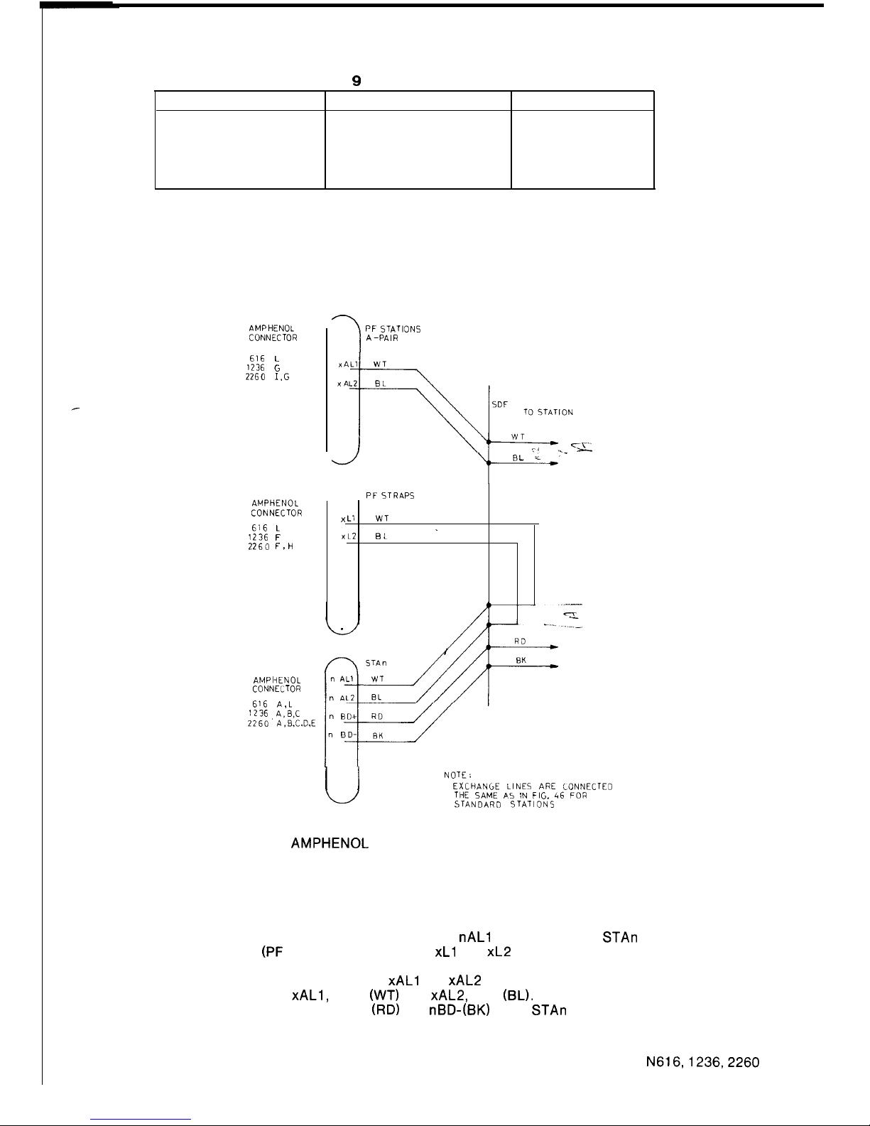
TABLE 9 MAXIMUM CABLE LENGTH
STATION LOOP RESISTANCE
CABLE LENGTH
TS-616 840hms l 490m
TS- 1236 740hms l 430m
TS-2260 640hms l
370m
DSS-6161236
52 Ohms 300m
DSS-2260 48 Ohms 280m
* These figures must be reduced by 10 Ohms or 60m if a Handsfree Console is attached to a
station.
Station internal wiring is shown in figure 49.
2.4.8
Powerfail Stations
AMPHENOL
CONNECTOR
616 L
1236
G
2260 I,G
AMPHENOL
CONNECTOR
616 L
1236
F
2260 F,H
PF STATIONS
A-PAIR
PF STRAPS
x
Ll
WT
.
XL2
EL
AMPIiENOL
CONNECTOR
616 A,L
1236 A.6.C
2260’ A.B.C.D,E
I
I
NOTE:
EXCHANGE LINES ARE LONNECTED
THE SAME A5
IN
FIG. 46 FOR
STANDARD STATIONS
FIGURE 47 AMPHENOL CONNECTOR AND SDF TERMINATIONS
FOR POWERFAIL STATIONS
Jumpering is required at the S.D.F. when cabling for powerfail stations. This cabling allows
assigned stations to access an exchange line under powerfail conditions. Refer to figure 47 for
method of connection, n stands for station number and x is the exchange line number.
For powerfail stations, jumper the station A-pair,
nAL1
and nAL2 of the STAn connections, to
the powerfail strap
(PF
STRAPS) connections
xL1
and
xL2
corresponding to the exchange line
that is to be connected to the station under powerfail conditions. In this case the A-pair that is to
be cabled to the powerfail station is the xAL1 and
xAL2
connections of the PF STATION A PAIR.
They will be cabled as
xAL1,
white
(WT)
and
xAL2,
blue (BL). The B pair that is cabled to the
powerfail station is the normal nBD+
(RD)
and nBD-(BK) of the STAn connections.
Refer to table 10 and figure 50 for the dial leads connection to STB-B terminals. Note BK from
the dial is connected to the BK terminal on STB-B if a handsfree console is not used.
N616,1236,2260
75
ISSUE 1
Page 79
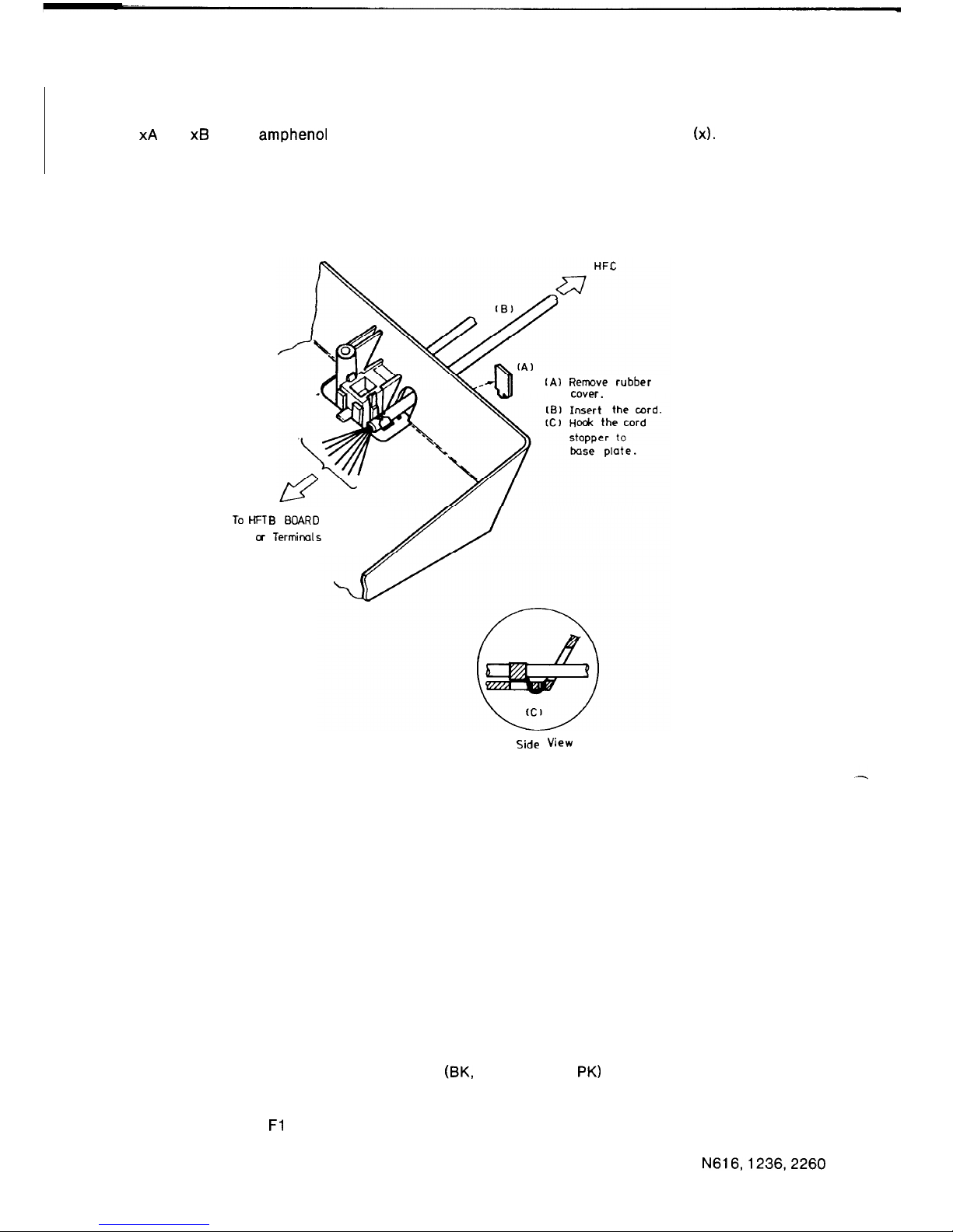
2.4.9
Powerfail Bell
When installing a powerfail bell connect wires from the bell, via the SDF, to POWERFAIL BELLS
xA
and XB on the amphenol connector corresponding the required exchange line (x).
2.4.10 Handsfree Console
Top View
To HFT
cr
IA)
Remove
rubber
cover.
‘B BOARD
Termirds
Side View
FIGURE 48 HANDSFREE CONSOLE CABLE INSTALLATION
Remove the front panel of handsfree console, then loosen the two screws holding the case
moulding to the base moulding and ensure that the slide switch designated “K” is set to 20V.
Replace the case moulding and front panel.
Unplug the station.
Remove the station front panel and case moulding.
Carefully, lift the keyboard.
Remove the hole cover from the base moulding and insert the handsfree console cord into the
hole (figure 48).
Connect the leads from the handsfree console to the terminals on the STB-B card in the station
as shown in table 10 and figures 49 and 50.
Take care to insulate each unused lead (BK, GN, LBL and
PK)
individually before plugging
in the station.
Remove the strap between C and BK in the standard station, and check that there is a strap
between RR and
Fl
Replace the keyboard, case moulding and front panel when the handsfree console is working.
N616,1236,2260
76
ISSUE 1
Page 80
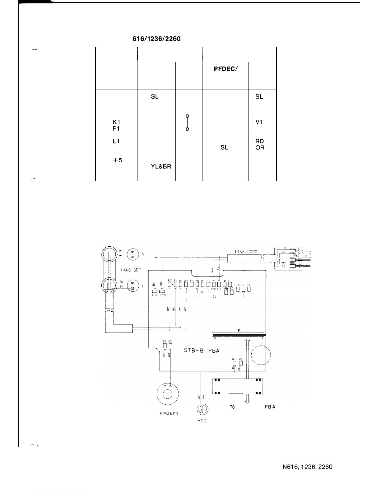
_-
_-
TABLE 10:
N
616/l 236/2260
HANDSFREE CONSOLE CONNECTION
r
STB-B
TERMINAL
BK
LK
FL
RR
Kl
Fl
B
Ll
RB
SG
+5
C
PF
STATION
HFC
SL
LGN
WH
VI
RD
OR
BL
YL&BR
STRAP
%
r
PF STATION
PFDEW
PFVF
DIAL LEADS
BK
OR
BL
RD
SL
BR
GN
HFC
SL
LGN
BR
WH
Vl
i”R
BL
YL
NOTE: 1
Remove the strap between C and BK in the standard station.
2
Remove BK dial lead from BK to FL on the STB-B for a powerfail station.
SPEAKER
TO
KEYBOARD
PBA
MIC
FIGURE 49 STB-B STATION BOARD ASSEMBLY AND WIRING
FOR A STANDARD STATION
N616,1236,2260
77
ISSUE 1
Page 81
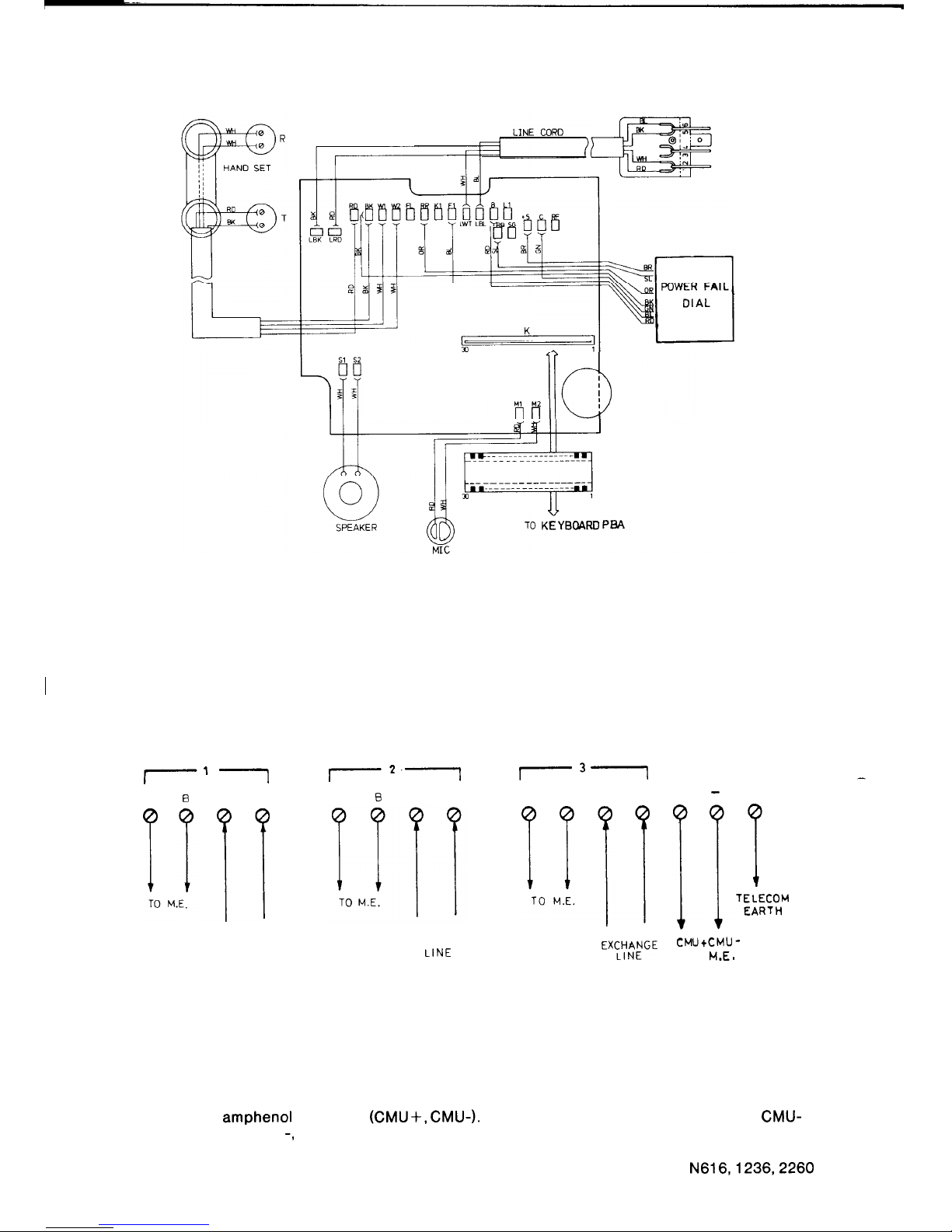
STB-B PBA
FIGURE 50 STB-B STATION BOARD ASSEMBLY AND WIRING FOR
A POWERFAIL STATION
I
2.4.11
Call Metering Unit
I’1
A
0
LA LB
~4-l
TO M.E.
TE LECOM
EXCHANGE
LINE
A
0
LA LB
TELECOM
EXCHANGE
LINE
r31
A
B LA LB
I-H
TO M.E.
TELECOM
EXCL%ENGE
FIGURE 51 CALL METERING UNIT WIRING
+ - E
CMUtCMU-
TO
M.E.
The unit is capable of counting meter pulses for three exchange lines. Terminate the exchange
lines on the CMU before terminating them at the SDF. The CMU derives its power from the main
equipment, amphenol connector
(CMU+,
CMU-). Make connections between CMU+ and CMU-
via the SDF to + and -, respectively, on the CMU. A Telecom metering earth is required to detect
meter pulses and this must be connected to the CMU. (Refer to figure 51).
N616,1236,2260
78
ISSUE 1
Page 82
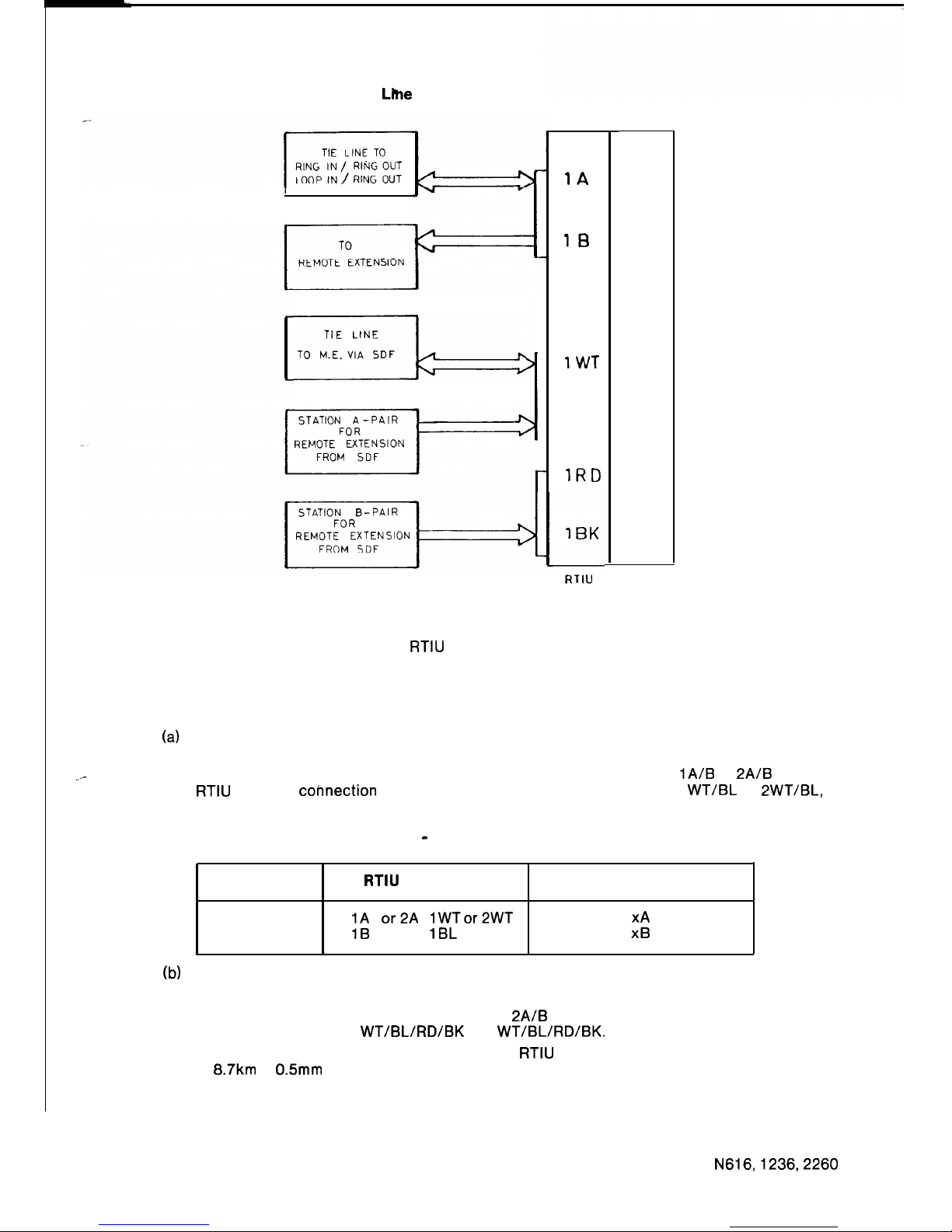
2.4.12
Remote Extension and Tie
Llhe
Interface Unit
I
OR
xg/&
OR
1A
2A
2B
1WT
1 BL
1RD
2w-T
2 BL
2RD
2BK
RTIU
TERMINAL
DESIGNATIONS
FIGURE 52
RTIU
TERMINAL CONNECTIONS
Boards are simply plugged into the designated slots in the RTIU. Terminal connections are as
follows. (Refer to figure 52.)
(a)
Tie lines
_-
A Tie line takes the place of an exchange line. Hence the Exchange Line Key now becomes
a Tie Line Key for the appropriate line. The Tie Line terminates on
IA/B
or
2A/B
on the
RTIU
and the
cohnection
to the main equipment is taken from 1
WT/BL
or
2WT/BL,
respectively.
TABLE 11 - TIE LINE CONNECTION
TIE LINE
RTIU TERMINAL
MAIN EQUIPMENT TERMINAL
A
1A or2A lWTor2WT
xA
B
1B
2B 1BL 2BL
XB
(b)
Remote Extensions
A remote extension takes the place of a station.
The remote extension terminates on 1 A/B or
2A/B
and the 4-wire station connection to the
main equipment is via 1
WT/BL/RD/BK
or 2
WT/BL/RD/BK.
Refer to table 12 and figure 52.
The loop limit for a remote extension using the
RTIU
and RXB is 1500 Ohms corresponding
to 8.7km of 0.5mm cable.
79
N616,1236,2260
ISSUE 1
Page 83
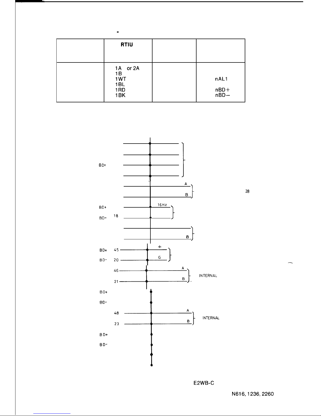
STA
CONNECTOR A
PLUG
SIGNAL DESG
PI N
40
LWT
AL1
LBL
AL2 15
BD+
41
:
1
LRD TO STATION 27
LBK
BD- 16
AL1 42
“I
27
STA
AL2
TO INTERNAL EXTENSION 28
17
B
28
BDt
BD-
AL1
STA AL2
43
,. 16HZ
FROM RGU
18
,.
OUT
44
A
TO INTERNAL EXTENSION 29
19
I3
29
BD*
BD-
:,i I}
TO RGU
AL1
STA
AL2
1: 1)
TO
,NTERNAL
EXTENSION30
30
BDt
BD-
47
22
t
AL1
STA AL2
31
i3D+
BD-
:“,
i}
TO
lNTERNAL
EXTENSION 31
49
TABLE 12 -REMOTE EXTENSION CONNECTION
REMOTE
RTIU CABLE WIRE MAIN EQUIPMENT
EXTENSION
TERMINAL COLOUR
CONNECTION
A
B
1A or2A
1B
2B
1WT
2WT
1BL 2BL
1RD
2RD
1BK 2BK
White
nAL1
Blue
nAL2
Red
nBD+
Black
nBD-
2.4.13 EPWB-C and Ring Generator Unit (Internal Extensions)
24
50
25
FIGURE 53 EXAMPLE OF WIRING FOR AN E2WB-C
INSTALLED IN POSITION ESTB-C/3
80
SDF
N616,1236,2260
ISSUE 1
Page 84
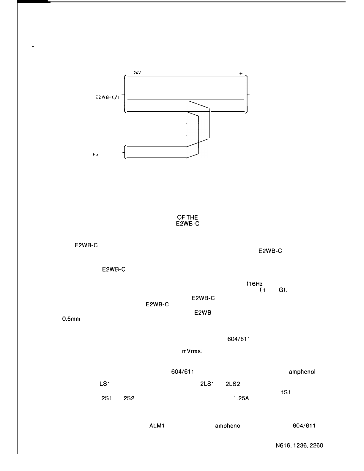
-
SDF
TO
EZWB-C/l
+
24V
t
GND
RING
RING
t
RING
TO
E2
WB-C/2
RING
+
G
16Hz
1
TO RGU
OUT
J
FIGURE 54 CONNECTION
OFTHE
RING GENERATOR UNIT
FOR TWO E2WB-C BOARDS
The E2WB-C board replaces an ESTB-C board to provide four internal extensions. A Ring
Generator Unit is required and is capable of supplying ring voltage for two E2WB-C boards. The
RGU and internal extensions are connected to the main equipment via the SDF. The stations
corresponding to the ESTB-C board position are replaced by internal extensions and the RGU
when using the E2WB-C board. Refer to figure 53 for an example.
The A-pairs are connected to two-wire internal extensions, the B-pair of the first internal
extension of each board is connected to ring voltage from the RGU (16Hz and OUT), and the
B-pair of the second internal extension is used to supply power to the RGU (+ and
G).
If the RGU is used to provide ring voltage to two E2WB-C boards, then the supply voltage must
only be connected from the first E2WB-C board. Refer to figure 54.
The loop limit for an internal extension using the E2WB is 700 Ohms corresponding to 4km of
0.5mm cable.
2.4.14
External Music Source and Background Music
Connect the external music source input to Ml/M2 from the
604/611
plug and socket via the
SDF. The music source connection has an input impedance of 600 ohms. The level of the
incoming signal must be between 50 and 300
mVrms.
2.4.15
External Paging Loudspeakers
The loudspeakers are connected to a
604/611
plug and socket and wired to the amphenol
connectors via the SDF. Connect the external paging loudspeakers to the LOUD SPEAK
connections 1
LSl
and 1 LS2 for external zone 1 and
2LSl
and 2LS2 for external zone 2.
Relay contacts are provided for each external paging zone. They are designated
1Sl
and 1
for zone 1 and
2Sl
and 2S2 for zone 2. The relay contact rating is 1.25A at 24Vdc.
The output power of the loudspeaker amplifier is 2 watts into an 8 ohm load.
2.4.16 Alarm Detector
ER
s2
Connect the alarm detector to
ALMl
and ALM2 on the amphenol connector via the
604/611
plug and socket and the SDF. The system detects the opening or closing of a dry metallic
contact, depending on system programming.
N616,1236,2260
81
ISSUE 2
Page 85
2.5 BOARD INSTALLATION INSTRUCTIONS
Before inserting boards into the ME rack, the following preliminary work is required.
*WARNINGS*
A.
This equipment contains a considerable number of MOS, and other static sensitive
components. To reduce the incidence of the premature failure due to static discharge, the
following precautions MUST be taken:
0
Always ensure that power is disconnected before plugging PBAs.
0
Always discharge static from yourself by touching a conductive part of the main
equipment before handling boards.
0
Handle PBAs by the edge or by the handles. Do not handle PBA tracks, components
or edge connectors (contaminants introduced by fingers can cause corrosion and
high resistance connections).
0
Components are physically delicate. Finger pressure on a component can fracture,
but not necessarily break component leads: a future fault.
To protect against physical damage and damage due to static discharge, PBAs must
ALWAYS be wrapped in aluminium foil (e.g. cooking foil) and inserted into an
ANTI-STATIC plastic bag and placed in the protective container provided with the new
item. In the case of the ECMB remove the battery and package separately.
These procedures apply equally to both working and faulty PBAs. Careless handling,
storage and transporting will cause secondary or future faults.
B.
To prevent the likelihood of damage to electronic components, power should be switched
off before working on the systems.
s
C.
The cabling between the main equipment and stations is polarity sensitive. It is essential
that the correct polarity be maintained from the main equipment to the
stations,and
pairs
must not be swapped. Care must be exercised when checking voltages on cabling. Do not
short or bridge between terminals as this will cause fuses on the ESTB boards to blow.
WIRE
603 PLUG/
WIRE
COLOUR 610 SOCKET
DESIGNATION
WT White
:
AL1
A-pair
BL Blue
AL2
RD Red
1
BD+ B-pair
BK Black
5
BD-
D.
Power supplies are powered from the 240 volt mains supply and hazardous voltages are
present within. Do not attempt to repair these devices.
E.
ECMB- A,B, & D BOARDS
0
If these PBAs are replaced, all site dependant data and abbreviated dial numbers are
lost. It will be necessary to re-programme the system.
0
The battery may be changed by removal of the daughter board, BTB-A, (without loss
of any programmed data) while the ECMB power is on.
0
The press button
(SW41
must be pressed to reset the crosspoints of the system after
replacing ESTB or ELNB boards when the power is on.
82
N616,1236,2260
ISSUE 2
Page 86
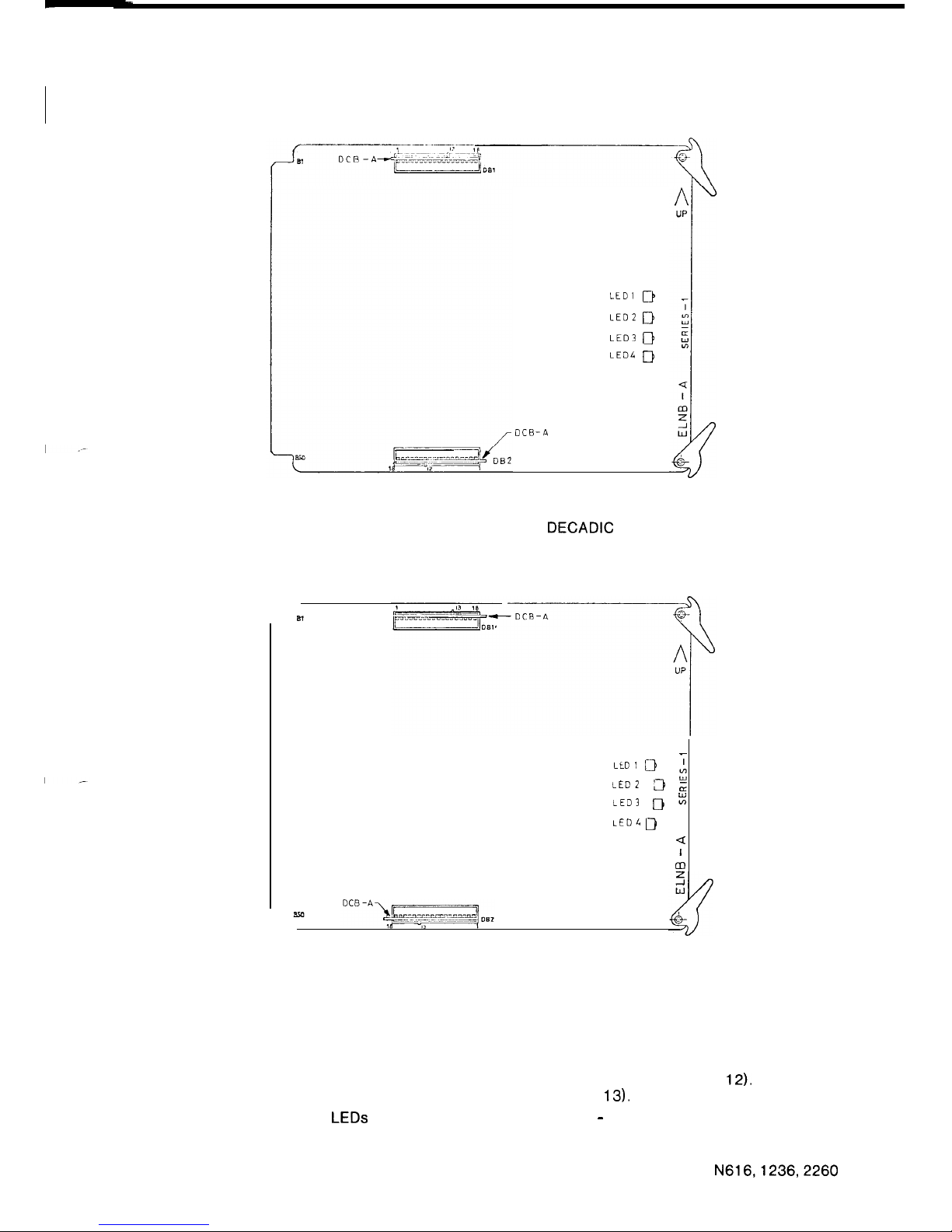
2.51
ELNB-A
LCD1 B
LED2 D
LED3 0
LED4 D
DCB-A
FIGURE 55 ELNB-A, DCB-A POSITION FOR A DECADIC EXCHANGE LINE
LLOl 0
-i
z
iED 3 rr
LED3 D :
LED4 D
Q
I
m
FIGURE 56 ELNB-A, DCB-A POSITION FOR AVF EXCHANGE LINE
There are two DCB-A plug-in daughter boards on this board. The DCB-A board must be
correctly plugged into the connector, according to the type of exchange line used.
Figure 55 shows the location for a decadic exchange line (keying location is pin
12).
Figure 56
shows the location for a VF exchange line (keying location is pin
13).
The ELNB-A board has LEDs to indicate exchange line status - LED1 for the first line, to LED4
for the fourth line. A steady LED indicates that the line is seized, a flashing LED indicates an
incoming call and a flickering LED indicates decadic dialling.
N616,1236,2260
83
ISSUE 1
Page 87
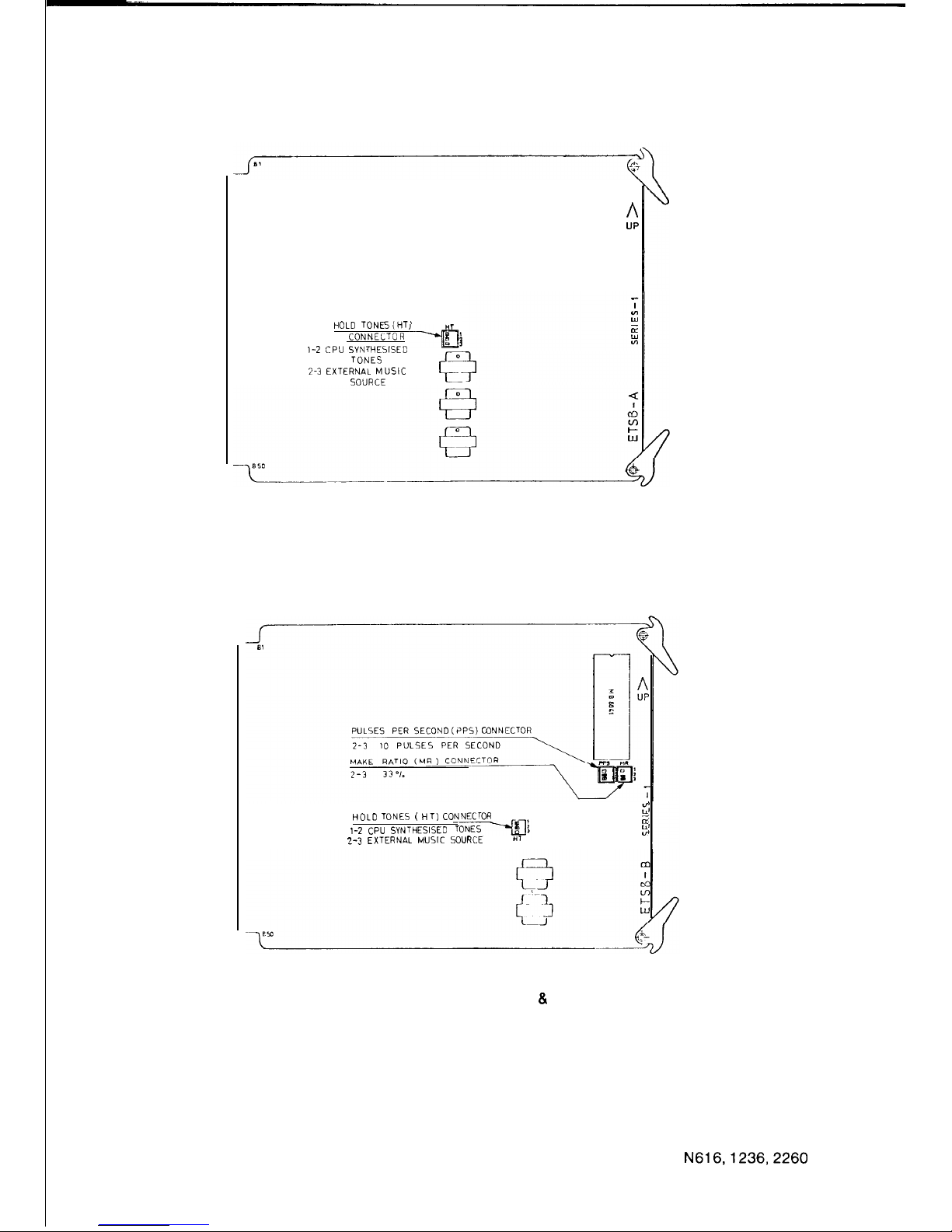
2.5.2
ETSB-A and ETSB-B
A
UP
HOLD
TONEs(HT)
CONNELTOR
1-2
CPU SYNTHESISED
---@
TONES
2-3 EXTERNAL MUSIC
SOURCE
FIGURE 57 ETSB-A, HT CONNECTOR LOCATION
;:
HOLD TONES ( HT)
CONNECTOR
E
1-2 CPU
SYNTHESISED
:
2-3 EXTERNAL MUSIC
SOURCE
FIGURE 58 ETSB-B/C LOCATION OF HT, PPS 8. MR CONNECTORS
The link on the HT connector which selects the music source for music on hold must be
correctly inserted according to the following information.
Link Between
Music On Hold Music Source
l-2
Internal, CPU Synthesised Tones
2-3
External Music Source
Refer to figures 57 and 58 for the location of the HT connector on the board.
N616,1236,2260
84
ISSUE 1
Page 88
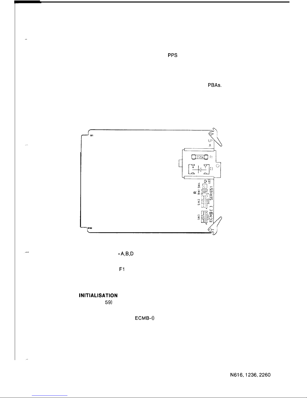
2.5.3
ETSB-B and ETSB-C
There are two connectors, PPS and MR, used to set the pulsing speed and make break ratio for
decadic dialling. The links are located as follows:
PPS Connector
Pulsing Speed
l-2
20
PPS
2-3
10 PPS (Standard Setting)
MR Connector
Make Ratio
l-2
30%
2-3
33% (Standard Setting)
Refer to figure 58 for the location of the PPS and MR connectors on the PBAs.
*PRECAUTION*:
The
links must be in the same position for both ETSB-B and ETSB-C cards in the N 2260.
2.5.4 ECMB-A, ECMB-B and ECMB-D
FIGURE 59 ECMB - A,B,D FUSE, BATTERY AND SWITCH LOCATIONS
Refer to figure 59. The fuse Fl is a 250mA fuse, which protects the battery from possible
damage due to an accidental short circuit. Be sure that the fuse is not blown and then install the
attached battery. Ensure that the battery is connected with the correct polarity. A LED is
provided on the board to light if the battery voltage is low.
POWER-UP
INITIALISATION
The SW1 switch (figure
59)
is used to clear the RAM memory and initialise the data base when
power is applied for the first time. Check that the SW1 switch is in the OFF(M) position before
powering up the system for the first time. After power is applied to the system, set the switch to
the ON(S) side without removing the
ECMB-0
board or turning off the power. The initial values
of the system data are given in section 2.7.
85
N616,1236,2260
ISSUE 2
Page 89
ASSIGNING THE DSS STATION(S)
SW3 is used to assign the number of the first DSS station, SW2 is used to assign the number of
the second DSS station if two DSS consoles are used. When the second DSS console is not
equipped set SW2 to all ones. The first DSS console must always be assigned. The bits 1,
2,3 &
4 assigns the TEN’s number and bits 5, 6, 7 8 8 assign the UNIT’s number. Once a DSS station
number is assigned, the DSS console number is automatically the DSS station number plus one.
Numbers equal to or greater than 36 (N 616), 55 (N 1236) and 79 (N 2260) are prohibited for use
as the DSS station. The N 616 is provided with a dedicated DSS console port (number
361,
therefore, it is recommended that it be used so that the full 16 station ports may be used.
In this case the DSS station port will be set as 35. The numbers are set as follows:
No.0
No.1
No.2
No.3
No.4
No.5
(1)
I I
I I
I
I
I (1) High
(0)
I I I I
I I I II I II
I
II I I
(0)
Low
1234 1234
1234 1234 1234 1234
(5
6 7
8) (5
6 7
8)
(5 6 7
8)
(5
6 7
8) (5
6 7 8)(5
6 7
8)
No.6
No.7 No.8 No.9
All Ones
(1’ II
I I I
I
I I
I I I I
(1)
High
(0)
I I I
I I I
I I
1234
1234 1234
1234 1 2 3 4
(O’
Low
(5
6 7 8) (5 6 7
8)
(5
6 7 8) (5 6 7 8) (5 6 7
8)
Example, the following switch setting is for the DSS station to be connected to port number
35.
Note:
Automatically the DSS console is assigned and must be connected to port
number 36.
I I
I I
I I
I I
I:;
1234 5678
Refer to figure 59 for the location of switches.
Now, the system may be programmed from the Test and Programming Unit (TPU-N).
CROSS POINT RESET
The push button, SW4, is used to manually reset the crosspoint switches in the system. This
must be operated each time a board is replaced while the power is on.
86
N616,1236,2260
ISSUE 2
Page 90
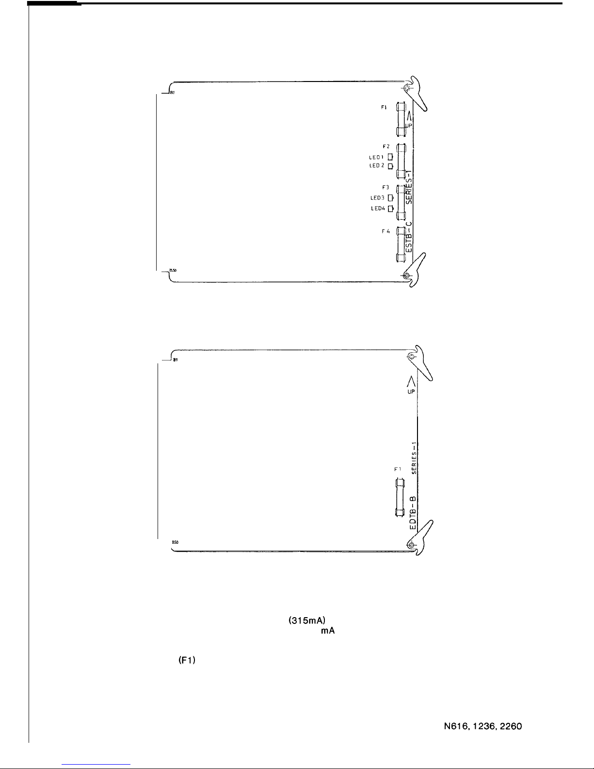
2.5.5
ESTB-C and EDTB-B
FIGURE 60 ESTB-C FUSE AND LED LOCATION
FIGURE 61 EDTB-B, FUSE LOCATION
Each station port is provided with a 375mA (315mA) 3AG fuse. The port corresponding to the
DSS Console must have a 1 A fuse, replace the 375 mA fuse with the 1 A fuse packaged with the
DSS console. As an example, station number 35 was assigned as the DSS station port in the
example above, therefore, port number 36 is assigned as the DSS console port automatically.
Then, the first fuse
(Fl)
in the ESTB-C-5 position must be replaced. In the case of the N 616, the
fuse on the EDTB-B card must have a 1 A rating.
Refer to figures 60 and 61 for fuse locations and Table 13 to find the fuse associated with each
port. On the ESTB-C board there are four LEDS to indicate station handset status. LED1 for the
first station to LED4 for the fourth station. The LED lights steadily when the station handset is off
hook.
N616,1236,2260
87
ISSUE 1
Page 91
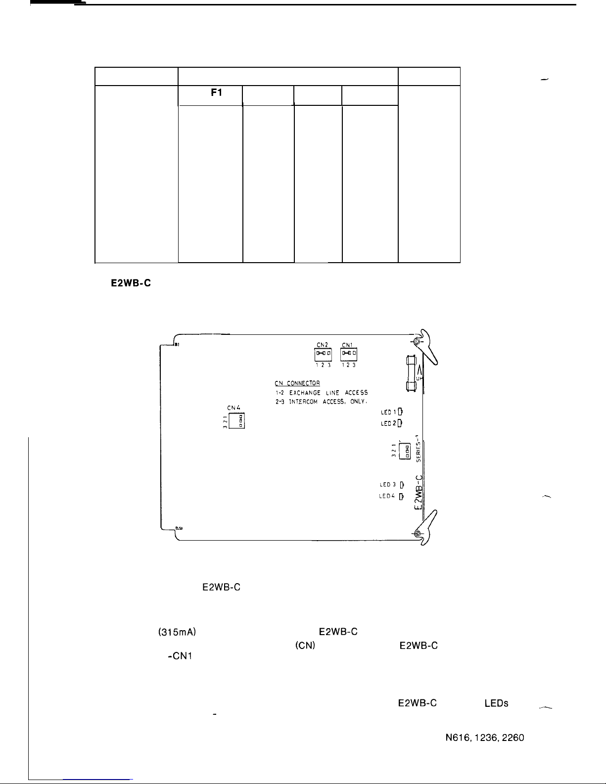
TABLE 13 FUSE LOCATIONS
ESTB BOARD
STATION PORT NUMBER
Fl
F2 F3
F4
-1
20
21
22 23
-2
24
25
26
27
-3 28 29 30
31
-4
32
33
34
35
-5 36 37 38
39
-6
40
41
42 43
-7
44
45 46
47
-8
48 49 50
51
-9 52 53 54
55
-10 56 57 58
59
-11
60
61
62
63
-12
64 65 66
67
-13
68 69
70
71
-14
72
73 74 75
-15
76
77
78 79
2.5.6 EPWB-C
SYSTEM
N616
N 1236
N 2260
CN2
CNl
--
CN
CONNECTOR
1-2
EXCHANGE LINE ACCESS
2-3
1NTERCOM ACCESS, ONLY.
CN
L
LED 1
D
LED 2
D
CN3
;
LEDL D
:
FIGURE 62 E2WB-C LOCATION OF INTERCOM/EXCHANGE LINE
ACCESS CONNECTORS, FUSE AND LEDS
A single 375mA (315mA) 3AG fuse is provided on the E2WB-C board for the RGU power supply.
An intercom/exchange line access connector
(CN)
is provided on the E2WB-C board for each
internal extension -
CNl
for extension one to CN4 for extension four. The link is used as follows:
Link Between
l-2
Extension has exchange line access
2-3
Extension has intercom access only
Refer to figure 62 for location of the CN connectors on the board. The
E2WBC
board has LEDs
to indicate extension status - LED1 for extension one, to LED4 for extension 4. The LED lights
when there is a dc loop to the extension i.e. off hook and flickers to indicate decadic dialling.
N616,1236,2260
88
ISSUE 1
-
--.
-
Page 92
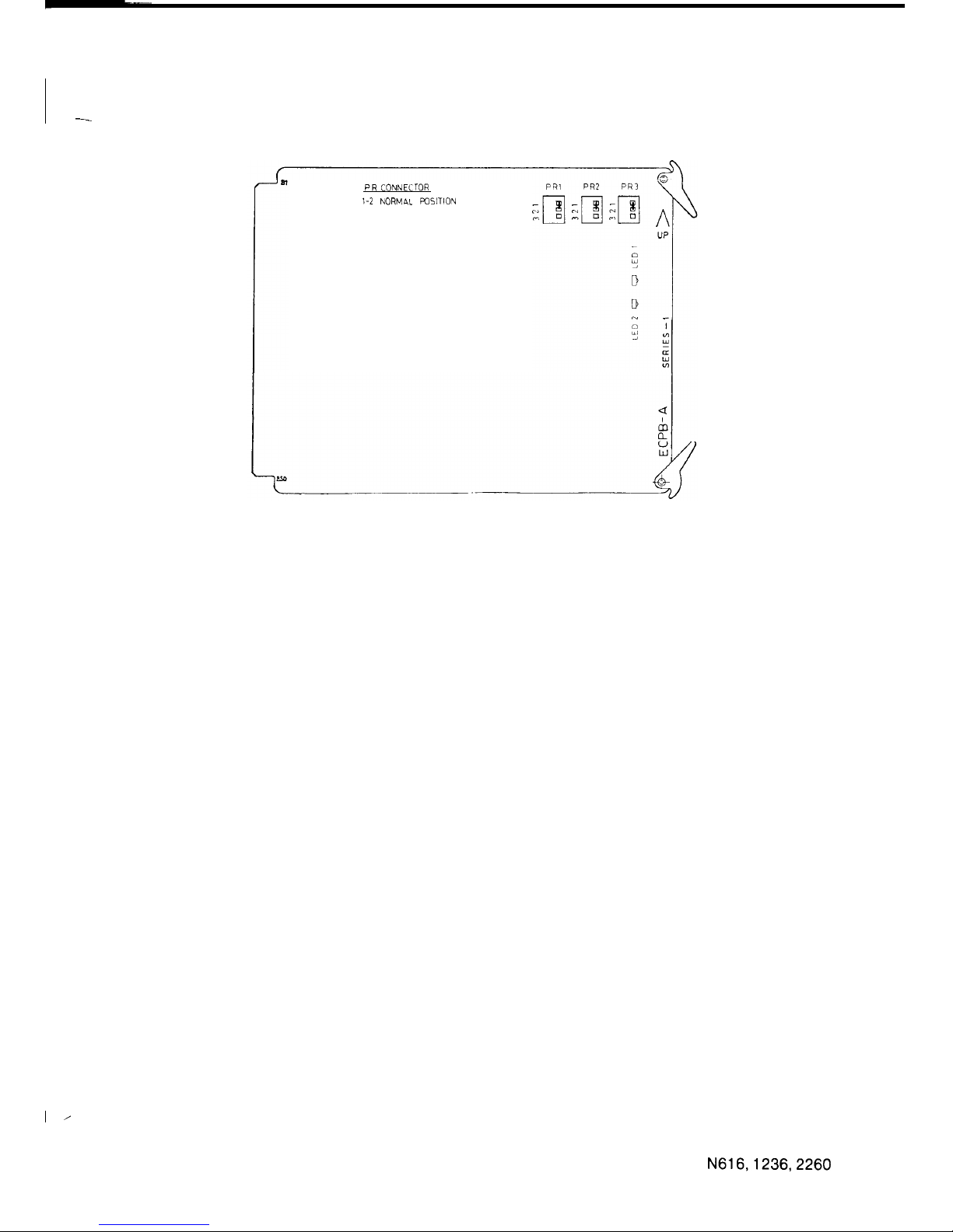
2.5.7
ECPB-A
-
PR
CONNECTOR
1-2
NORMAL
POSITION
FIGURE 63 ECPB-A LOCATION OF PR CONNECTORS AND LEDS
Three PR connectors are provided on the ECPB-A board, and they must have the link inserted
between l-2.
On the ECPB-A are LEDS to indicate CPU status. LED1 flashes at 60 IPM to indicate that the
program is running, but goes steady (ON or OFF) when the system is in programming mode.
LED2 flashes at 300 IPM to indicate that data transmission to stations is taking place. Refer to
figure 63.
I ’
89
N616,1236,2260
ISSUE 1
Page 93
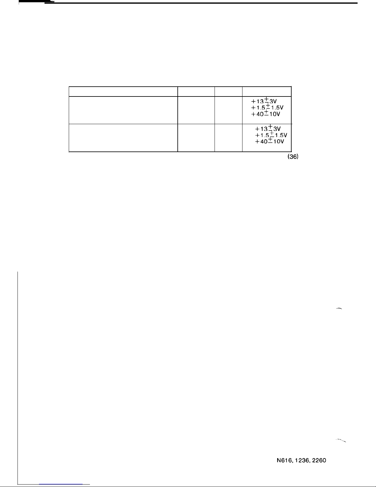
2.6 POWERING UP THE SYSTEM
When the system has been cabled and terminated and all printed circuit boards have been
correctly set-up and installed, power-up the system.
Before installing the stations measure the voltages at the 610 sockets to ensure that the cabling
is correct.
__
TABLE 14 STATION AND DSS CONSOLE VOLTAGES
COLOUR
PIN VOLTAGES
Station Voltages:
A-PAIR
WT
2
+13+-3v
BL
6
+1.5+1.5v
B-PAIR
RD
1
+40+1ov
BK
5
REF
DSS Console:
A-PAIR
WT
2
*
+13+3v
BL
6
l
+1.5+-1.5v
B-PAIR
RD
1
+40+1ov
BK
5
REF
*
The N616 DSS console A-pair voltages are OV when using the DSS port
(36)
on the
EDTB-B board.
When the voltages are correct at all stations, install the stations. System programming is now
possible.
90
N616,1236,2260
ISSUE 1
Page 94

2.7 INSTALLATION PROGRAMMING
2.7.1
Programming Data
-
When the system is powered up for the first time, programmed data must be initialised. To
initialise data, turn power off and set the SW1 switch on the ECMB board to the OFF(M) position.
Turn power on, wait for ten seconds, then set the SW1 switch to the ON(S) position. The initial
values of the data are given in section 2.7.6.
A unit designated as a Test and Programming Unit
(TPU-NJ
has been developed. The TPU-N
must be inserted into the DSS Console socket when programming or testing the system. To
enter programmed data the system must be placed in programming mode. To do this, press the
programme enable button using a pencil through the hole of the TPU-N.
The MW LED on the console will light to indicate that the system is in programming mode.
When the system is in programming mode normal operations are halted - existing calls are
maintained, incoming exchange line calls will ring but cannot be answered unless you go out of
programming mode. No new calls can be made. Programmed data can be entered using DSS
keys to select a data category, and the dial of the DSS station (when OFF HOOK) is used to
enter the relevant data. Programme data is indicated by the TPU display, and the associated
DSS LED will light to indicate which data category is being programmed. Note that if two DSS
console ports are provided, programming is possible from the first console only.
Data is programmed as follows: place the system into programming mode. Operate the DSS key
associated with the data category to be programmed and the LED should light. Enter data by
dialling from the DSS station (OFF HOOK). Dial
“*”
to send the write command and dial
“#”
to
terminate a data category or data block within a category.
When data programming is completed, depress the programming button to return the system to
operational mode and the MW LED will go OFF. If there is a fault in the programmed data, alarm
tone is heard from the TPU, the DSS LED associated with the faulty data category
WIII
light and
the system will not return to operational mode. If this occurs, the programming button should be
despressed again to return the system to programming mode.
The faulty data category must be reprogrammed
2.7.2 Checking Programmed Data
Programmed data may be reviewed as follows: Place the system in programming mode by
depressing the programming button on the DSS Console ensure that the MW LED is lit, and take
the DSS Station OFF HOOK. Data is indicated on the TPU display in the same format as for
programming data.
For system assignments, operate the DSS key associated with the data category. The
associated DSS LED will light and data will be displayed on the console. If the data is in more
than one part dial
‘I*‘”
to review further data. To terminate the review of a data category dial
“*‘”
then
‘I#“.
For type of exchange line assignment, operate DSS key 34, dial the line number, then
“*‘“.
To review other lines dial
‘I*‘“,
line number,
“*“.
Terminate review of data category by
dialling
“*‘“, “#‘I.
For station assignments (except call forwarding and audible signalling, which are similar to
system assignments), operate the associated DSS key, dial the station number, then
“*‘“.
To
review other stations dial
I‘*‘“,
station number,
“*“.
To terminate review of data category dial
“* “9 “#“.
For access barring data (except number length limiter, which is similar to system assignments),
operate AC then the associated DSS key. Review digits one by one by dialling
I‘*‘“,
to display the
next code dial
I‘#“.
To terminate the data category dial
I‘#”
till the associated DSS LED goes off.
When data has been checked depress the programming button to return the system to operation
mode. Check that the MW LED goes off.
Unplug the TPU when programming has been completed and connect the DSS Console if
provided with the system.
91
N616,1236,2260
ISSUE 2
Page 95
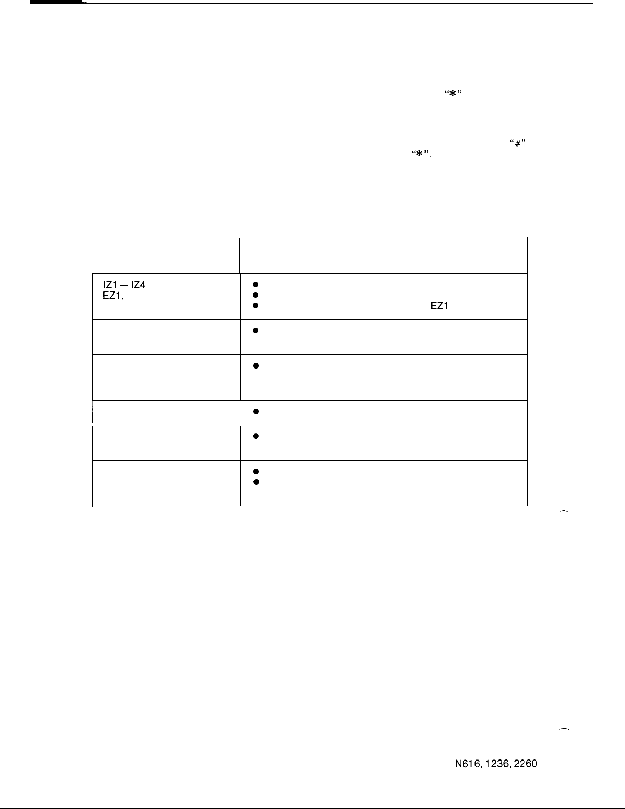
2.7.3 Modifying Programmed Data
Except for access barring, programmed data can be re-written as it is checked. If incorrect data
is found whilst checking programmed data, dial new data from the DSS station (when OFF
HOOK). The new data will be shown in the display on the DSS console. Dial
“*”
to write in the
new data, then continue with checking programmed data. Data is erased by dialling “00” as new
data.
For access barring, incorrect data must be reprogrammed.
A code may be erased using the following procedure; operate the associated DSS key, dial
‘I#”
to step through to the code to be modified, erase the code by dialling
“*I”.
To programme new
data use the procedure described in section 2.7.5.14.
It is not possible to programme some data categories while system facilities are active. Table 15
shows the conditions under which the system will not allow data to be programmed. If this
occurs the associated DSS LED will not light when the DSS key is operated.
TABLE 15 CONDITIONS WHEN PROGRAMMING IS NOT ALLOWED
CATEGORY ACTIVE FACILITY
IZl -
I24
EZl,
EZ2
0
All call paging in progress.
0
Associated zone paging in progress.
0
Incoming call audible signalling to
EZl
or EZ2.
Line Grouping
Audible Signalling
0
Incoming call to system.
Dial Sender
Earth Recall or
Switchhook Flash
0
Exchange line busy.
Meet-Me-Answer
0
Paging in progress.
Exclusive Line
0
Line is in use (calling, incoming or
Hot Line
transferring).
Call Forwarding
0
Call forwarding in operation.
0
The station to be assigned as executive
is in Do-Not-Disturb mode.
When programmed data is modified, depress the programming button to return the system to
operational mode.
2.7.4 Re-Initializing Programmed Data
Programmed data may be reset to initial conditions as follows; turn power off and set the SW1
switch on the ECMB board to the OFF(M) position. Turn power on, wait for ten seconds, then set
the SW1 switch to the ON(S) position.
.-
2.7.5 Facility Programming
Press the programming button on the TPU. Lift the handset on the DSS station to allow the dial
to transmit data to the main equipment. In the following examples, “X” represents any
preprogrammed data.
--
92
N616,1236,2260
ISSUE 2
Page 96
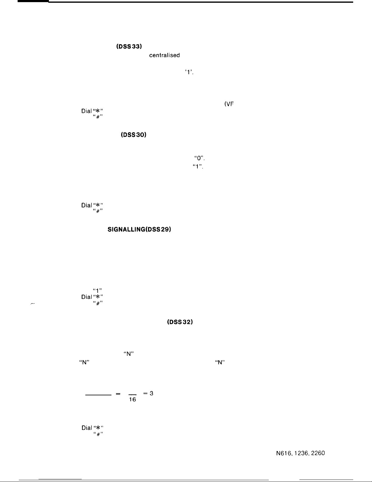
SYSTEM ASSIGNMENTS
2.7.5.1 DIAL SENDER (DSS
33)
DSS key 33 is used to assign the
centralised
dial sender as Decadic or VF.
If the exchange lines are VF, programme ‘0’.
If the exchange lines are Decadic, programme ‘1’.
Example: VF dialling
DISPLAY
Press DSS 33
0 0
0 x
Dial “0”
0 0
0
0
0/F lines)
Dial “*I’
0 0 0 0
Dial
“#‘I
0
0
0 0
DSS 33 LED goes off.
2.7.5.2 DSS OVERRIDE (DSS
30)
DSS key 30 is used to give the DSS console the possibility of overriding stations in Do Not
Disturb.
To disable override of Do Not Disturb, programme
“0”.
To enable override of Do Not Disturb, programme
“1”.
Example: Enable Override
DISPLAY
Press DSS 30 0
0 0
x
Dial “1” 0
0
0
1
(Override enabled!
Dial “*‘”
0 0
0 0
Dial
I’#”
0 0 0
0
DSS 30 LED goes off.
2.7.5.3 OFF HOOK
SIGNALLING
(DSS
29)
DSS key 29 is used to assign off hook audible signalling at all stations for intercom calls and
incoming exchange line calls.
To disable off hook signalling, programme “0”.
To enable off hook signalling, programme “1”.
Example: Enable Off Hook Signalling
DISPLAY
Press DSS 29
0 0 0 x
Dial
“1”
0 0 0 1 (Enabled)
Dial “*‘”
0 0 0 0
_-
Dial
“#‘I
0 0 0 0
DSS 29 LED goes off.
2.7.5.4 AUTOMATIC RING BACK TIMER
(DSS 32)
DSS key 32 is used to set the time a call will stay on exclusive hold before it rings back to the
holding station.
The timeout is given by the following formula:
TIMEOUT (seconds) =
“N”
x 16
where
“N”
is a single digit in the range 1 to 8. Therefore,
“N”
specifies the number of 16 second
periods required to make-up the timeout.
To disable automatic ring back, programme “0”.
Example: 48 Seconds Timeout
“N” =
TIMEOUT
=
48
=3
16
16
Press DSS 32
Dial “3”
Dial “*I’
Dial
“#”
DSS 32 LED goes off
DISPLAY
0 0 0
x
0 0 0 3
(48 seconds)
0 0 0 0
0
0
0 0
N616,1236,2260
93
ISSUE 1
Page 97
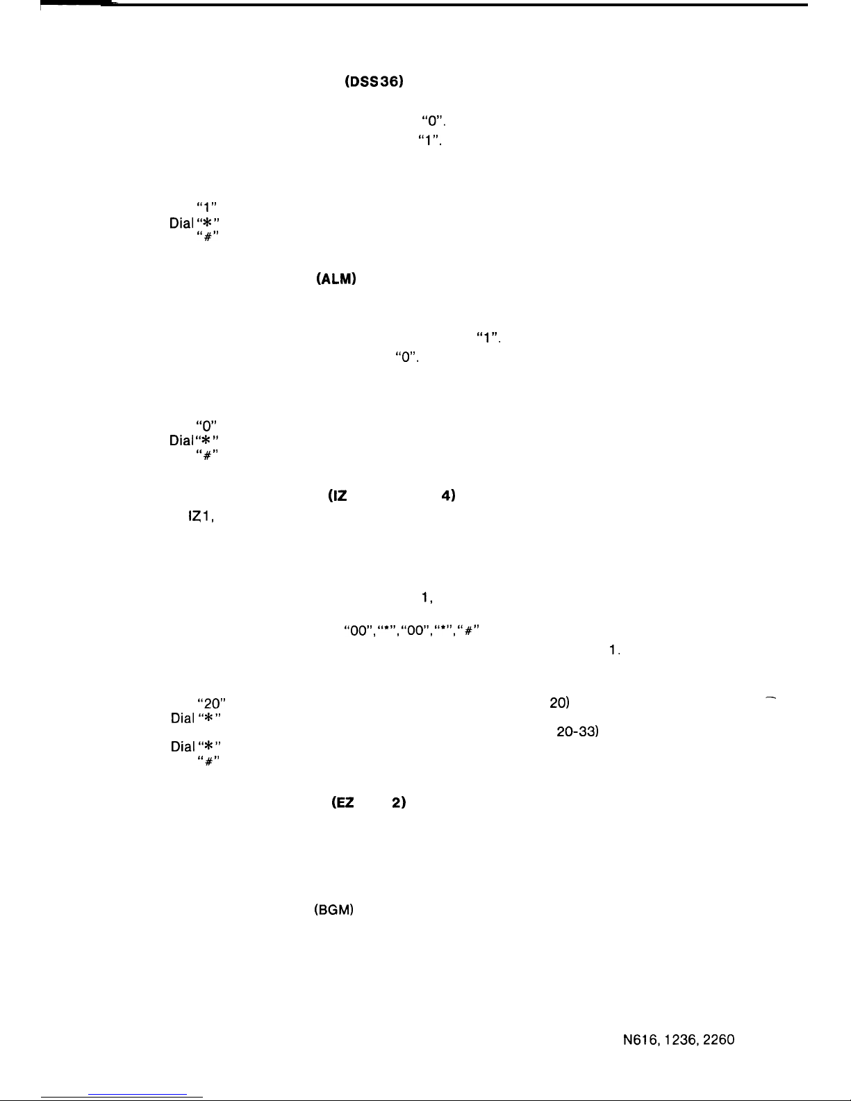
2.7.5.5 MEET-ME-ANSWER PAGING
(DSS 36)
DSS key 36 is used to enable the meet-me-answer paging facility.
To disable meet-me-answer paging, programme
“0”.
To enable meet-me-answer paging, programme
“1”.
Example: Enable Meet-Me-Answer Paging
DISPLAY
Press
DSS
36 0
0
0 x
Dial
“1”
0
0
0
1
(Enabled)
Dial
%‘”
0
0
0 0
Dial
“#‘I
0 0 0 0
DSS 36 LED goes off
2.7.5.6 ALARM CONTACT TYPE
(ALM)
DSS key ALM is used to specify the condition of the alarm contacts when the alarm is active.
If the contacts close when the alarm is active, programme “0”.
If the contacts open when the alarm is active, programme
“1”.
If no alarm device is connected, programme
“0”.
Example: No Alarm Device Connected.
DISPLAY
Press ALM
0 0 0 x
Dial
“0”
0 0 0 0
(No Alarm)
Dial “*
” 0 0 0 0
Dial
‘I#”
0 0 0 0
ALM LED goes off
2.7.5.7 INTERNAL ZONE PAGING
(IZ
1, IZ 2, IZ 3, IZ
4)
DSS keys IZ 1, IZ 2, IZ 3 and IZ 4 are used to set-up the zones within the system which will allow
selective paging. Two station numbers must be programmed to define a zone, the stations
programmed and each station with a number between the station numbers programmed are
assigned to that zone.
Note, zones must not overlap and nesting (placing one zone within another) is not allowed.
DSS key IZ 1 is used to assign stations to Zone 1, IZ 2, IZ 3 and IZ 4 are used to assign stations
to Zone 2, Zone 3 and Zone 4, respectively.
To disable this feature, programme
“OO”, “*“, “OO”,
“*I’,
“#”
in each zone.
Example: Programme stations 20 and 33 and all stations in between into zone
1.
DISPLAY
Press IZ 1
Dial
“20”
Dial “$”
Dial “33”
Dial
“*‘”
Dial
‘I#”
IZ 1 LED goes off
x x x x
2 0 x x
(station
20)
2 0 x x
2 0 3 3
(stations
20-33)
0 0 0 0
0 0 0 0
2.7.5.6 EXTERNAL ZONE PAGING (EZ 1, EZ 2)
When the system is connected to a loudspeaker paging system two sets of information can be
programmed.
DSS keys EZ 1 and EZ 2 are used to programme data for external zones 1 and 2, respectively.
Note that only EZ 1 is available with a 616.
The display is divided into two fields. The first field, the two digits on the left hand side, are used
to assign background music (BGM) for the external zone, it will be heard while there are no
paging announcements.
94
N616,1236,2260
ISSUE 1
Page 98
If background music is not required, programme
“0”.
If background music is required, programme “1”.
The second field, the two digits on the right hand side, are used to assign one of the exchange
line audible signalling groups.
The audible signalling group assigned to external paging may be programmed as one of the
following (refer to
2.7.5.12):
“0”
No exchange line audible signalling.
‘I II
1
1 st audible signalling group.
“2”
2nd audible signalling group.
“3”
3rd audible signalling group.
“4”
4th audible signalling group.
“5”
Common audible signalling, all lines.
“6”
Night transfer audible signalling.
Example: Provide background music and audible signalling from the 3rd group of exchange
lines for external zone 1.
DISPLAY
_-
Press EZ 1
Dial
“1”
Dial “*‘”
Dial “3”
Dial
“I”
Dial
“#”
EZ 1 LED goes off
0 x 0 x
0 1 0 x
(BGM provided)
0 1 0 x
0 1 0 3
(Group 3 assigned)
0 0 0 0
0 0 0 0
2.7.5.9 EXCLUSIVE LINES OR HOT LINES (DSS 51 to
56)
DSS keys used to assign exclusive lines or hot lines are as follows.
DSS Key for
Exchange Line Number
Exclusive or
Hot Line No.
616 system
1236 system
2260 system
51 for line-l
No. 5th
No. 11 th
No. 21 st
52 for line-2
No. 6th
No. 12th
No. 22nd
53 for line-3
No. 7th
No. 13th
No. 23rd
54 for line-4
No. 8th
No. 14th
No. 24th
55 for line-5
- -
No. 25th
l 56 for line-6
-
-
No. 26th
*
When using a 1236 DSS console for programming the unmarked key between MW and NT
must be used instead of key 56.
The display is divided into two fields of two digits each.
.--
Enter “00” before a station number to specify a exclusive line, and enter two station numbers to
specify a hot line between those stations.
NOTE: 1 When a hot line is provided the corresponding exchange line must not have an
exchange line connected. The exchange line circuit is used to provide signalling
tones.
2
An exclusive line must not be assigned to a remote or internal extension.
Example: Provide a exclusive line using line-3 (exchange line 23, 2260 system) for station
number
25.
DISPLAY
Press DSS 53
Dial
“00”
Dial %‘”
Dial “25”
Dial ‘I*‘”
Dial
‘I#”
DSS 53 LED goes off.
x x x x
(line -3)
0 0 x x
(exclusive line)
0 0
x x
0
0
2
5
(to
station
25)
0 0 0 0
0 0 0 0
N616,1236,2260
95
ISSUE 2
Page 99
Example: Provide a hot line between stations 26 and 34 using line-4 (exchange line 14, 1236
system).
DISPLAY
__-
Press DSS 54
x x x x
(exchange line
14)
Dial “26” 2 6 X X
(hot line between
Dial “*”
2 6 X X
station 26)
Dial “34” 2 6 3 4
(and station 34)
Dial “*”
0 0 0 0
Dial
“#‘I
0 0 0 0
DSS 54 LED goes off.
To change an existing exclusive line or hot line, enter “00” in both fields as shown in the
example, before programming new data.
Example: Cancel hot line-l
Press DSS 51
Dial “00”
Dial “*I”
Dial “00”
Dial %‘”
Dial
I‘#”
DSS 51 LED goes off.
Example: Cancel exclusive line-4.
Press DSS 54
Dial
“00”
Dial “*‘”
Dial “00”
Dial “*‘I
Dial
“#”
DSS 54 LED goes off.
DISPLAY
M N X
0 0
x
0 0
x
0 0 0
0 0
0
0 0 0
DISPLAY
0 0
P
0 0
P
0 0
P
0
0 0
0 0 0
0 0 0
Y
(MN and XY are station numbers)
Y
Y
0
0
0
Q
(PQ
is a station number)
Q
Q
0
0
0
2.7.5.10 EARTH RECALL OR SWITCHHOOK FLASH
(DSS
35)
When the system is connected to a PBX, earth recall or switchhook flash may be assigned.
DSS key 35 is used to assign the required facility earth recall or switchhook flash.
If neither earth recall nor switchhook flash is required, programme
“0”.
If earth recall is required, programme
“1”.
If switchhook flash is required, programme “2”.
Example: Earth recall
DISPLAY
Press DSS 35
0 0 0 x
Dial
“1”
0 0 0 1
(earth recall)
Dial “*‘”
0 0 0 0
Dial
“#”
0 0 0 0
DSS 35 LED goes off.
Important Note:
EXCLUSIVE LINES, EARTH RECALL or SWITCHHOOK FLASH key and HOT LINES require
conversion of exchange line key(s). There are 8 cases of exchange line key conversion.
Case- 1:
Case-2:
Case-3:
Case-4:
Case-5:
Case-6:
Case-7:
Case-8:
(Line-20)
(Line-l
0)
(Line-
4)
EXCHANGE
EXCHANGE
EXCHANGE
EXCHANGE
EXCLUSIVE
EXCHANGE
EXCHANGE
EXCHANGE
KEY ASSIGNMENT
(Line-21
1
(Line-221
(Line-l
1)
(Line-l
2)
(Line-
5)
(Line-
6)
EXCHANGE EXCHANGE
EXCHANGE
ER or FL
HOT
ER or FL
EXCLUSIVE
ER or FL
HOT ER or FL
EXCHANGE
HOT
EXCHANGE EXCLUSIVE
EXCLUSIVE
HOT
2260 Station
1236 Station
616 Station
-
96
c
N616,1236,2260
ISSUE 2
Page 100
2.7.5.11
TYPE OF EXCHANGE LINE
(DSS
34)
‘-
Each exchange line connection must be defined as a local exchange connection or a PBX
connection. This information is necessary for redial and access barring. Each line must be
specified in sequence, lines must not be omitted. This also applies when equipping the system.
NOTE: For exchange lines connected to a PBX the code used to get an outside line (trunk
access code) must be programmed using DSS key 44 as part of the access barring data.
DSS key 34 is used to allocate each exchange line, first enter the exchange line number,
including leading zero.
If the exchange line is connected to an exchange, programme
“0”.
If the exchange line is connected to a PBX line, programme “1”
Example: Exchange line 1 is connected to an exchange.
Exchange line 2 is connected to a PBX line.
Press DSS 34
Dial
“01”
Dial “*‘I
Dial “0”
Dial “*‘I
Dial
“02”
Dial “*‘”
Dial “1”
Dial “I”
0
0
0
Dial
“#‘I
DSS 34 LED goes off.
DISPLAY
0 0 0 0
(Exchange line
1)
0
1
0 0
0
1
0
x
0
1
0 0
(Exchange.)
0 0 0 0
0
2
0
x
(Exchange line
2)
0
2
0
x
0
2
0
1
(PBX line)
0 0
0
0
0 0 0 0
2.7.5.12 EXCHANGE LINE AUDIBLE SIGNALLING (DSS 20 to 28 and NT)
All stations have visual indication of incoming calls, but audible signalling is a programmed
option. The options are:-
(i) COMMON SIGNALLING; stations assigned to common signalling will hear audible signalling
whenever there is an incoming call on any exchange line. A maximum of 10 stations can be
assigned to common signalling.
(ii) GROUP SIGNALLING; exchange lines connected to the system are divided into 4 groups
with a maximum of 10 stations assigned to each group. Stations may be assigned to only one of
the groups. An incoming call on an exchange line in group 2 will only signal to stations assigned
to group 2.
(iii) NIGHT TRANSFER; this mode operates when the NT key on the DSS Console is operated.
Effectively this adds’assigned stations (up to 20) to the common signalling group while the
system is in night transfer mode.
In general, a station may be programmed to only one of the above options
(i),
(ii) or (iii). The only
exception is that stations assigned to group signalling may also be assigned to night transfer
signalling. Stations assigned to common signalling must not be assigned to night transfer - this
will result in a programming error.
2.7.5.12.1
COMMON/GROUPED SIGNALLING MODE (DSS 20)
DSS key 20 is used to programme the audible signalling mode for incoming calls. There are two
modes of signalling, common signalling only, or common and group signalling together.
If only common audible signalling is to be used, programme
“0”.
If common and grouped signalling is provided, programme
“1”.
Example: Common and Grouped signalling.
DISPLAY
Press DSS 20
0 0 0 x
Dial
“1”
0 0 0 1
(Common and Grouped
Dial “*I”
0 0 0 0
Signalling)
Dial
“#‘I
0
0 0 0
,-
DSS 20 LED goes off.
97
N616,1236,2260
ISSUE 2
 Loading...