

Telecom Australia Commander N616, Commander N1236, Commander N2260 Maintenance Manual
I
Corn
616
I
mander
N
1236
& 2260
Business Systems
I
-
In’stallation
&
Maintenance
Manual
This manual
contains propnetary
Information and IS to be
Issued
and used solely
withtn
Telecom
Australia
The manual was prepared by Standard Telephones and
Cables Pty Ltd for, and
In conjunct!on with.
Telecom
Australia
I
P
49
Telecom
Australia

CONTENTS
1.
GENERAL
1
.l
INTRODUCTION
1.2 FACILITIES
1.3 OPERATING INSTRUCTIONS
1.4 SYSTEM CAPACITIES AND COMPONENTS
1.4.1 Systems Capacities
1.4.2 Systems Components
1.4.3 Block Diagram and Description
1.5 MECHANICAL DESCRIPTION
2.
INSTALLATION
2.1
INTRODUCTION
2.2 SALES INFORMATION
2.3 LOCATION AND MOUNTING OF EQUIPMENT
2.3.1 Main Equipment
2.3.2 Power Supply
2.3.3 System Distributing Frame
2.3.4 Stations
2.3.5 Powerfail Bell
2.3.6 Remote Extension and Tie Line Interface Unit
2.3.7 Call Metering Unit
2.3.8 Ring Generator Unit
2.4 CABLING AND TERMINATING METHODS
2.4.1 General
2.4.2 AMP Champ Connectors
2.4.3 S.D.F. Cabling
2.4.4 Lightning Protection
2.4.5 Exchange Lines
2.4.6 Earth Recall
2.4.7 Stations and DSS Console
2.4.8 Powerfail Stations
2.4.9 Powerfail Bell
2.4.10 Handsfree Console
2.4.1 1 Call Metering Unit
2.4.12 Remote Extension and Tie Line Interface Unit
2.4.13
E2WB-C and Ring Generator Unit (Internal Extensions)
2.4.14 External Music Source and Background Music
2.4.15 External Paging Loudspeakers
2.4.16 Alarm Detector
PAGE
1
3
7
29
29
30
35
41
49
50
57
58
58
59
61
62
62
63
63
64
64
64
65
73
74
74
74
75
76
76
78
79
80
81
81
81
N616,1236,2260
(i)
ISSUE 2

CONTENTS
(Cont.)
PAGE
3.
MAINTENANCE
2.5 BOARD INSTALLATION INSTRUCTIONS
2.5.1 ELNB-A
2.5.2 ETSB-A and ETSB-B
2.5.3 ETSB-B and ETSB-C
2.5.4 ECMB-A, ECMB-B and ECMB-D
2.55
ESTB-C and EDTB-B
2.5.6 E2WB-C
2.5J
ECPB-A
2.6 POWERING UP THE SYSTEM
2.7 INSTALLATION PROGRAMMING
2.7.1 Programming Data
2.7.2 Checking Programmed Data
2.7.3 Modifying Programmed Data
2.7.4 Re-initializing Programmed Data
2.7.5 Facility Programming
2.7.6 Summary of Facility Programming and
2.8 FUNCTIONAL TEST
2.8.1
Exchange Line Test
2.8.2 Intercom Test
2.8.3 Station Test
2.8.4 DSS Console Test
2.8.5 Miscellaneous Tests
2.8.6 Internal Extension Test
2.8.7
RTIU
Tests
Initial Values
2.9
RECORDS
3.1
TEST EQUIPMENT AND MAINTENANCE AIDS
119
3.2 TEST POINTS
119
3.3 POWER SUPPLY INDICATORS
123
3.4 MAINTENANCE PROCEDURES
124
3.5 FAULT FINDING FLOWCHARTS
128
3.6 SUGGESTED REPAIR ACTIONS
173
3.7 REPAIR PROCEDURE
184
4. APPENDIX 1
Hardware Requirement Block Diagrams
Installation Parts Check List
Maintenance Parts Check List
Serial and Item Number Parts List
185
82
83
84
85
85
87
88
89
90
91
91
91
92
92
92
105
107
107
109
112
113
114
115
116
117
(ii)
N616,1236,2260
ISSUE 2
’
1
GENERAL
1 .l INTRODUCTION
The N 616, N 1236 and N 2260 are electronic key telephone systems providing 6 exchange
lines and 16 stations, 12 exchange lines and 36 stations, 22 exchange lines and 60 stations,
respectively. They are a family of key telephone systems using common software and hardware
modules, packaged to provide various economical solutions. The stations have modern
functional styling.
The main equipment, stations and DSS console are controlled by micro processors with masked
programs providing a wide range of facilities demanded by the users of key systems.
A prominant feature of this equipment compared to previous key systems is the elimination of
multi-wire cabling in favour of 4 conductor
(2
pair) cabling.
*WARNINGS*
A.
This equipment contains a considerable number of MOS, and other static sensitive
components. To reduce the incidence of the premature failure due to static discharge, the
following precautions MUST be taken:
0
Always ensure that power is disconnected before plugging
PBAs.
0
Always discharge static from yourself by touching a conductive part of the main
equipment before handling boards.
0
Handle PBAs by the edge or by the handles. Do not handle PBA tracks, components
or edge connectors (contaminants introduced by fingers can cause corrosion and
high resistance connections).
0
Components are physically delicate. Finger pressure on a component can fracture,
but not necessarily break component leads: a future fault.
To protect against physical damage and damage due to static discharge,
PBA’s must
ALWAYS be wrapped in aluminium foil (e.g. cooking foil) and inserted into an
ANTI-STATIC plastic bag and placed in the protective container provided with the new
item. In the case of the ECMB remove the battery and package separately.
These procedures apply equally to both working and faulty PBA’s. Careless handling,
storage and transporting will cause secondary or future faults.
B.
To prevent the likelyhood of damage to electronic components, power should be switched
off before working on the systems.
.--
C.
The cabling between the Main Equipment and Stations is polarity sensitive. It is essential
that the correct polarity be maintained from the Main Equipment to the Stations and pairs
must not be swapped. Care must be exercised when checking voltages on cabling. Do not
short or bridge between terminals as this will cause fuses on the ESTB boards to blow.
WIRE
COLOUR
WT White
BL Blue
RD Red
BK Black
603 PLUG/
WIRE
610 SOCKET DESIGNATION
;
AL1
AL2
1
BD+
5
BD-
N616,1236,2260
1
ISSUE 1

D.
Power supplies are powered from the 240 volt mains supply and hazardous voltages are
present within. Do not attempt to repair these devices in the field.
E.
ECMB- A,B, 8 D BOARDS
0
If these PBA’s are replaced, all site dependant data and abbreviated dial numbers are
lost. It will be necessary to re-programme the system.
0
The battery may be changed by removal of the daughter board (without loss of any
programmed data) with the ECMB power up, i.e. power on.
0
The press button
(SW4)
must be pressed to reset the crosspoints of the system after
replacing ESTB or ELNB boards when the power is on.
I
N616,1236,2260
2
ISSUE 1
1.2 FACILITIES
1.2.1
INTERCOMMUNICATION BETWEEN STATIONS
Each station is able to establish an internal (intercom) call to another station by dialling the
desired stations number.
Automatic intercom line selection is provided, this requires only one Intercom Line Key per
station.
Assigned stations can call a particular station using a direct access key, Hot Line Key. In
addition, each system has a capacity for two Direct Station Select
(DSS)
Consoles
incorporating a Busy Lamp Field (BLF).
1.2.2 ALTERNATE POINT ANSWERING (CALL PICK-UP)
Any other station can answer an intercom call to another station by lifting the handset and
dialling the called stations number.
1.2.3
ADD ON CONFERENCE
A station may add another station onto an existing intercom call to set-up a three party intercom
conference using the ADD ON feature key.
1.2.4 BREAK-IN, OVERRIDE
Executive Break-in is provided by Hot Lines. Hot Line calls have priority over all other call types.
The DSS Console has priority to override an intercom call. An intrusion tone is signalled when
the DSS Console overrides a call. The DSS Console may be programmed to override stations in
Do Not Disturb.
I
1.2.5
DIRECT EXCHANGE LINE ACCESS
In general, any station can access any exchange line to answer an incoming call or make an
outgoing call. The only exception is exclusive lines.
Up to a maximum of 6 Exclusive Exchange Lines may be provided with the limitation of one per
station. An
ExecutiveSecretaiiaI
configuration can be arranged where only the secretary’s
station responds to
incomming
calls and the secretary may extend the calls to the executive
using an intercom call.
1.2.6
LAST NUMBER
REDIAL
The user may recall the last number
dialled
by operating the asterisk
‘*’
button after seizing an
exchange line and depressing-the Dial Control (DC) Key. When the system is connected to a
PABX via exchange lines, a 3 second pause is generated automatically when dialling through
the PABX.
1.2.7
MULTIPLE EXCHANGE LINE ANSWER
The status of each exchange line is displayed at every station facilitating the possibility of
answering an incoming call at any station. The exception being Exclusive Exchange Lines,
which only appear on one station.
1.2.8
CONFERENCE CALL (SIMULTANEOUS OUTSIDE LINE CALL)
A conferencing facility is provided which allows up to three internal stations to be connected to
an exchange line or, two exchange lines connected to an internal station.
1.2.9 COST CONTROL
Three forms of cost control are available. The systems can perform Access Barring by analysis
of
dialled
digits. Dialled digits are compared with codes preprogrammed into the system’s data
base. The system caters for 5 classes of barring.
Class A
-
Unrestricted
ClassB
-
Barred to ISD
ClassC
-
Limited allowed STD and ISD codes
Class D
-
Barred to STD
ClassE
-
Barred outgoing access when the system is installed behind a PABX.
N616,1236,2260
3
ISSUE 1

The second form of cost control is the use of a Call Metering Unit which records the metering
pulses on an exchange line basis.
A third, but less useful, form of cost control is provided by a facility allowing No Access to a
group of Exchange Lines. This facility allows the exchange lines to be split into two groups and
selected stations are not permitted to make calls using exchange lines in the second group.
1.2.10
TIE LINES
By use of a Remote Extension and Tie Line Interface Unit the system can handle two types of tie
lines, Ring-in/Ring-out and Loop-in/Ring-out. The tie lines take the place of exchange lines.
1.2.11
PBX RECALL
Two methods of PBX Recall are available, Earth Recall or Switchhook Flash (Timed Loop
Break). The key for this facility takes the place of an exchange line key.
1.2.12 TRANSFER
A manual transfer is required when transferring an exchange line call. The station holds the
exchange line, notifies the other station using an intercom call and the station accepting the call
must seize the exchange line by operating the corresponding exchange line key.
The DSS Console may perform a Revertive Transfer. After calling the other station using a DSS
key the attendant may operate the Signal Call (SC) facility. The call is then signalled at the
transferred station. If the call remains unanswered after 20 seconds the call reverts to the DSS
station.
1.2.13 HOLD
Both manual and automatic hold are provided in the systems. Indications are provided for the
Hold, I-Hold and Exclusive Hold conditions.
Stations are provided with manual hold by operating the Hold Key, I-Hold is indicated at the
holding station and Hold is indicated at all other stations. A second operation of the Hold Key
will place the exchange line on Exclusive Hold, no other station can accept the call.
The DSS Console has an Automatic Hold, used when transferring exchange line calls to another
station. After answering an exchange line call the exchange line is automatically held when the
DSS attendant operates a DSS Key, an Internal/External Paging Key or the All Call Key.
1.2.14
CALL FORWARDING
Intercom calls and exclusive line calls are forwarded to a preassigned station after this facility
has been envoked by operating the Do Not Disturb Key at the unattended station. A maximum of
4 pairs of stations can have this facility.
1.2.15
ABBREVIATED
DIALLING
Each station is provided with a 16 number store with a capacity of 16 digits for each number
The station may store and recall numbers at any time.
1.2.16 PRIVACY
Privacy is provided for intercom calls as well as exchange line calls. The only exception is that
the DSS Console has the posibility to override a handsfree talk-back intercom call, following an
intrusion tone.
1.2.17 POWER FAILURE
When the power fails the exchange lines are automatically switched through to preassigned
stations set-up by the wiring of the connectors on the main equipment. In this condition the
preassigined stations can accept incoming calls and originate outgoing calls. All other facilities
are inoperative.
The system data base stored in CMOS memory is retained by a lithium battery.
1.2.18 AUTOMATIC RING BACK
When an exchange line is put on exclusive hold longer than a preset time the call is rung back to
the holding station.
4
N616,1236,2260
ISSUE 1
1.2.19
NIGHT SWITCHING
Operation of the Night Transfer Key at a DSS Console directs ring signalling for all incoming
-.
calls to the programmed night transfer station(s).
1.2.20
MESSAGE WAITING
A visual indication is displayed at an unattended station to indicate that a message is waiting at
a DSS Console. A call to the DSS Console resets the message waiting indication.
1.2.21 SUPERVISORY TONES
The following supervisory tones are generated within the system:
Intercom Dial Tone
Busy Tone
Intrusion Tone
Number Unobtainable Tone
Ring Tone
1.2.22 MUSIC ON HOLD
Provision has been made for internally generated synthesized tones, or music from an external
source, to be transmitted to a caller who has been placed on hold.
1.2.23
BACKGROUND MUSIC
_~
Provision has been made so that music, supplied from an external source, can be transmitted
over the station speakers and external zone paging speakers, if required. The music can be
turned on and off at each station and is automatically turned off when the handset is off-hook.
1.2.24
PUSHBUTTON DIALLING
Each station is equipped with a push button pad. Dialling, Decadic or VF, is controlled by a
centralised dialling facility in the main equipment. A dialling station signals to the centralised
dialling facility via a data transfer and the decadic or VF signals are sent out on the exchange
line.
During power failure, powerfail stations have decadic or VF dials switched in at the station.
1.2.25
STANDARD TELEPHONES (P-WIRE INTERNAL EXTENSION)
It is possible to connect 2-wire standard telephones with decadic dialling using a special
interface card and a ring generator unit in place of a 4-wire station interface card.
1.2.26 REMOTE EXTENSIONS (REMOTE STATION, P-WIRE TELEPHONE)
A remote extension can be connected to the systems using a Remote Extension and Tie Line
Interface Unit which provides the 4-wire to 2-wire conversion, generation of ring voltages and
tones. The remote extension must be a decadic telephone.
1.2.27 VISUAL INDICATIONS
A visual indication is provided at each station to show the status of exchange lines (Free,
Incoming ring, Hold, I-Hold, Exclusive Hold and Busy), intercom lines (Free, Busy and
Microphone on), and system facilities (Do Not Disturb, Monitoring, Message Waiting
etc).
The
DSS Console has a Busy Lamp Field
(BLF)
which displays the status of each station in the
system. In addition the DSS Console displays the number of the station(s) holding held
exchange lines.
1.2.28 MONITORING (ON-HOOK
DIALLING)
Each station may originate and monitor the progress of a call using the station speaker without
lifting the handset.
1.2.29 HANDSFREE
TALKBACK
ON INTERCOM CALLS
The called party has a full handsfree facility when called via an intercom call. A single tone
announces the call and the voice of the calling party is heard through the station speaker, at the
same time the called station’s microphone is activated and the intercom status lamp flashes to
indicate the microphone is on. The microphone may be cut-off by operation of the DND key.
A volume control is used to adjust the sound level transmitted through the station speaker.
N616,1236,2260
5 ISSUE 1

1.2.30 PAGING CALLS
Three paging facilities are provided, All Call, Internal Zone and External Zone Paging.
ALL CALL PAGING transmits an announcement over the station speakers of all stations and
through the external loudspeakers.
INTERNAL ZONE PAGING calls can be made through station speakers to one of four zones.
Stations are programmed to be in one of the four zones when the system is installed.
EXTERNAL ZONE PAGING calls are broadcast over external loudspeakers.
1.2.31 MEET-ME PAGING
The systems provide a facility which allows a person being paged to respond by simply lifting
the handset of any station through which the announcement was heard and pressing the “8”
button to be automatically connected to the caller. The caller must have pressed the asterisk ‘*’
button following the announcement.
1.2.32 FULL HANDSFREE OPERATION
Full handsfree operation is possible by adding a Handsfree Console to a station. This provides
handsfree operation at that station for every type of call.
1.2.33 CALL SIGNALLING
Incoming calls are signalled by a tone caller through the station speaker. Different signals are
provided for intercom calls and exchange line calls. Each station may be programmed to signal
when there is an incoming call on any exchange line or only on a group of exchange lines or it
may not signal for incoming exchange line calls. The volume control provides a means of
adjusting the volume of the tone caller.
1.2.34
ALARM SIGNALLING AT THE DSS CONSOLE
A supervisory or alarm device, which has as an output a set of contacts which open or close,
can be connected to the system. When the device is activated a flashing LED and audible alarm
signal will be indicated at the DSS Console. While in night transfer mode the alarm will be
indicated at the night transfer station(s).
1.2.35 DO NOT DISTURB
The system can provide a Do Not Disturb facility for all stations depending how the system is
programmed. Operation of the DND key puts the station in Do Not Disturb mode. This will turn off
the background music, block all paging calls, send busy tone to intercom callers, stop audible
signalling and forward calls to another station if so programmed.
1.2.36 KEY LABELS
The keys have transparent plastic covers which can be removed by hand so that a typed or
handwritten label may be placed under the cover for easy key identification.
1.2.37
SIGNAL CALL
If after placing an intercom call in the usual manner, there is no immediate response, the call
can be signalled using ring signalling by dialling an extra digit. The caller will hear ring tone and
the called party must answer by lifting the handset and operating the ICM Key.
1.2.38
PRESELECTION
A user may preselect the facility that is to be used by operating the facility key and then lifting
the handset off-hook, providing the handset is lifted within 5 seconds.
1.2.39 CALLS TO BUSY STATIONS
While a station is off-hook and busy on a call, muted incoming audible signalling may be heard
through the station speaker, depending on system programming. In this case the user may
decide to hold the exchange line he is using and accept the incoming call.
1.2.40
NUMBER PLAN
The systems have a fixed numbering scheme. Stations are numbered from 20 up to the
maximum system size 35
(616),55
(1236) and 79 (2260).
N616,1236,2260
6
ISSUE 1
1.3 OPERATING INSTRUCTIONS
CONTENTS
1.3.1
1.3.2
1.3.3
1.3.4
STATION NOMENCLATURE
STATION LED INDICATIONS
SYSTEM TONES
STATION OPERATIONS
Placing an Exchange Line Call
Last Number Redial
On-hook Dialling
Abbreviated Dialling
Answering an Exchange Line Call
Holding an Exchange Line
Automatic Ring Back
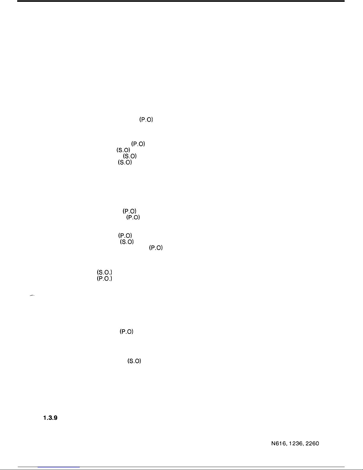
(P.0)
Transferring an Exchange Line Call
Multi Party Conference (Exchange Line)
Listen-in Monitoring
Switchhook Flash
(P.0)
Earth Recall
(S.0)
Exclusive Line
(S.0)
Hot Line Call
(S.0)
Preselection
Placing an Intercom Call
Signal Call
Answering an Intercom Call
Alternate Point Answering
Calls to a DSS Console Attendant
Three Station Intercom Conference
Do Not Disturb
(P.0)
Call Forwarding
(P.0)
Microphone Cut-off
Paging All Call
Internal
(P.0)
External
(S.0)
Meet-me Answer Paging
(P.0)
Message Waiting
Background Music Control
Power Failure
(S.O.)
SYSTEM OPTION, requiring additional hardware
(P.O.)
PROGRAMMABLE OPTION, depends on system configuration
1.3.5
1.3.6
1.3.7
DSS CONSOLE NOMENCLATURE
DSS CONSOLE LED INDICATIONS
DSS CONSOLE OPERATIONS
DSS Call
Automatic Exchange Line Hold
Digits Display
DSS Override
(P.0)
Automatic Ring Back
Signal Call
Message Waiting
Night Transfer
Alarm Indication
(S.0)
Battery Low Condition
1.3.8 OPTIONAL EQUIPMENT
Handsfree Console
Internal Extensions (Internal Stations)
Remote Extensions (Remote Stations)
Tie Lines
1.3.9
QUICK REFERENCE TABLE
N616,1236,2260
7
ISSUE 1
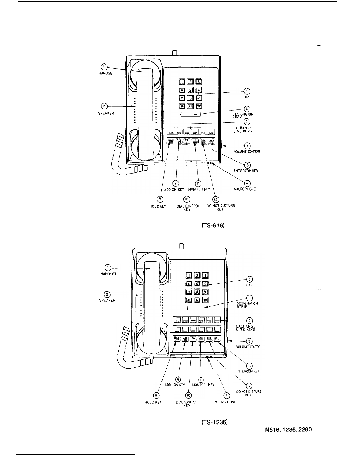
1.3.1
STATION NOMENCLATURE
o--
HANDSET
-
SPEAKER
-
HANDSET
o----
SPEAKER
d
0
6
10
b
12
------a
DIAL
------a
;F;FNATlON
------a
EXCHANGE
LINE KEYS
HOLD
KEV
DIAL CONTROL
DO
NOT DISTURB
KEY
KEY
FIGURE 1 N616 STATION (TS-616)
l-l
h
b
13
INTERCOM
KEY
\o
I
MICROPHONE
I
d ADD
AEVlMOkR
KEY
1 bs;lE
HOLD
KEY
DIAL CONTROL
MICROPHONE
KEY
EXCHANGE
LINE KEYS
FIGURE 3 N1236 STATION (TS-1236)
8
N616,1236,2260
ISSUE 1
HANDSET
1
?
1.
2.
3.
4.
5.
-
6.
7.
a.
9.
10.
11.
12.
13.
DO NOT
DISTURBKEY
VOLUME
CONTROL
d
Q
b
HOLD KEY
‘NTKEERyCoM
MICROPHONE
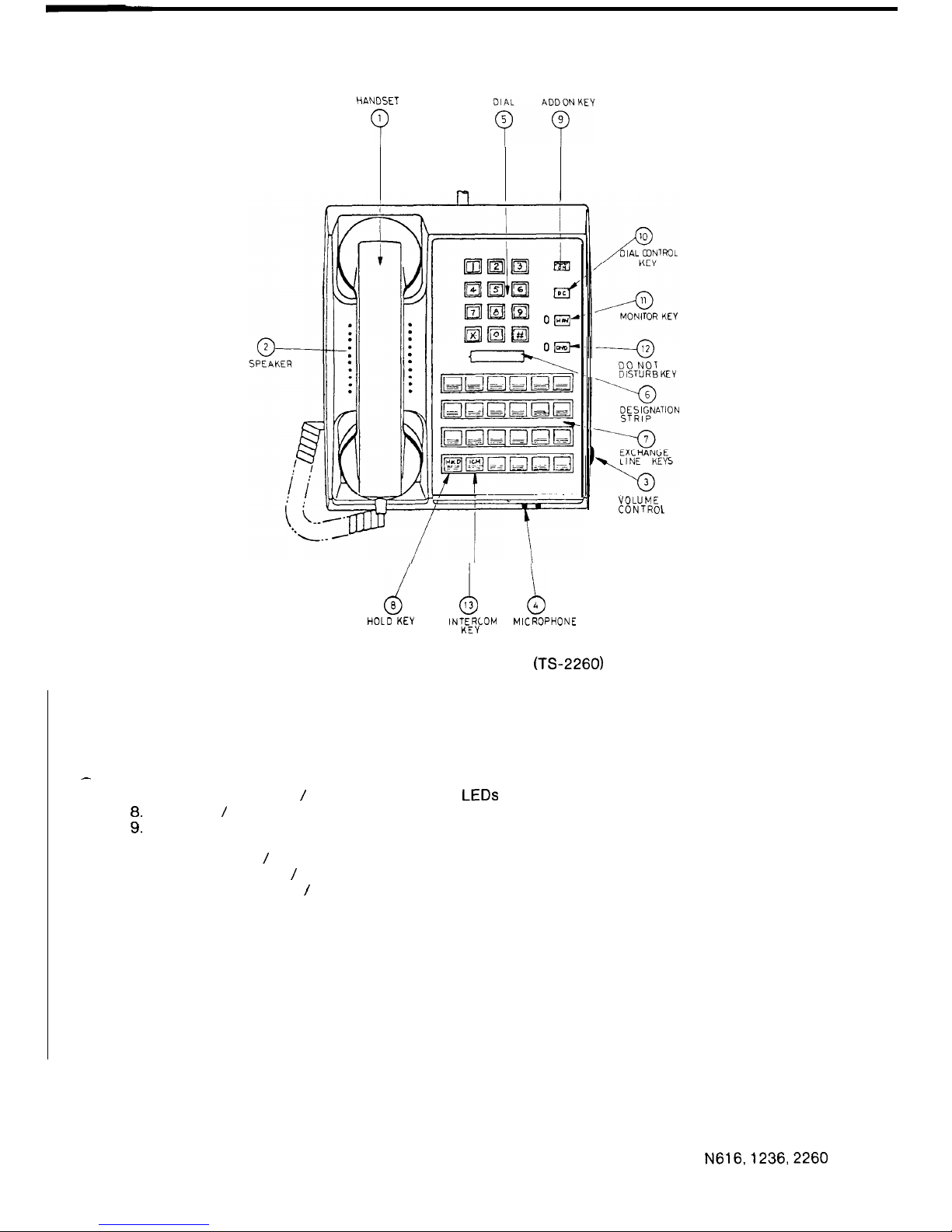
FIGURE 3 N2260 STATION (TS-2260)
Handset
Station Speaker
Volume Control
Microphone
Push-button Dial
Desighation Strip
Exchange Line Keys / Exchange Line Status LEDs
Hold Key / Message Waiting LED
Add On Conference Key
Dial Control Key
Monitoring Key / Monitoring Status LED
Do Not Disturb Key / Microphone Cut-off Key
Intercom Control Key / Intercom Status LED
When the system provides an Exclusive Line, Hot Line and Earth Recall or Switchhook Flash
the keys used for these facilities are automatically allocated. The last three exchange line keys
will be used depending on what facilities are required.
The keys are allocated as shown:
616
1236 2260
-4 -10 -20
Exclusive Line Key
-5
-11 -21 Exclusive Line Key or Hot Line Key
-6
-12 -22
Exclusive Line Key or Hot Line Key or Earth Recall Key or
Switchhook Flash Key
The exchange line keys are allocated from the last key to the third last key. If two facilities are
used, for example Exclusive Line and Earth Recall the Exclusive Line will be allocated to the
second last exchange line key.
Note:
If the system is fully equipped with exchange lines, then the station has lost the use of
the last common exchange lines.
N616,1236,2260
9
ISSUE 1
I
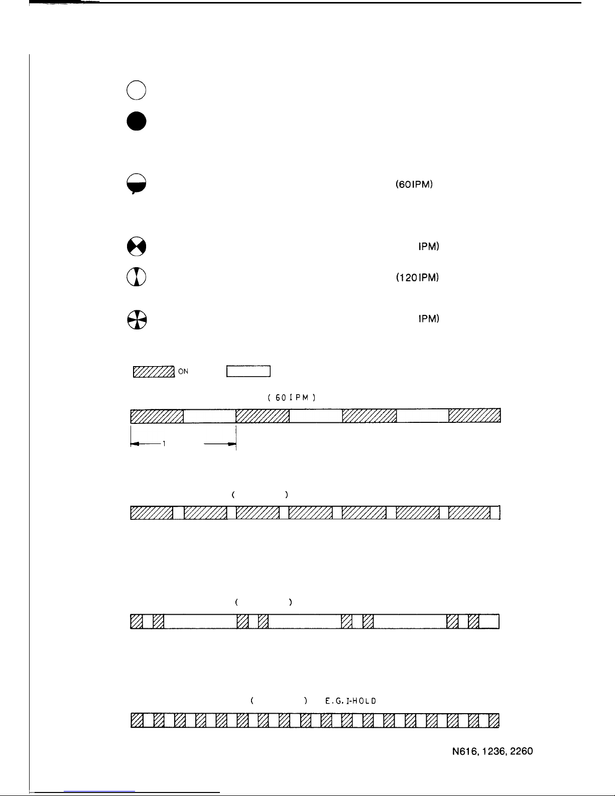
1.3.2 STATION LED INDICATIONS
c
0
Off
Steady
A
Slow Flash
8
Flash
aI
Flicker
Rapid Flash
l7zzzzaON
Free
Busy
On-Hook Dialling
Do Not Disturb
Listen-in Monitoring
Incoming Call
(60
IPM)
Intercom Call (Microphone off)
Microphone Off
Message Waiting
Hold
Exclusive Hold
Add On Standby
(120 IPM)
(120 IPM)
I-Hold
(300 IPM)
Intercom Call (Microphone on)
Hot Line Call
Automatic Ring Back
I-]
OFF
SLOW
FLASH
(601PM)
E.G. INCOMING CALL
Ll
SECOND
-/
FLASH
(
120 IPM
)
E.G.
HOLD
I
FLICKER
(
120 IPM
)
E.G. EXCLUSIVE HOLD
RAPID FLASH
(
300 I P M
1
E.G.I-HOLD
FIGURE 4 LED INDICATIONS
N616,1236,2260
10
ISSUE 1
1.3.3 SYSTEM TONES
Ring Tone
Constant Tone
Slow Repeating Tone
(60 pulses per minute)
Fast Repeating Tone
(120 pulses per minute)
Single Tone Burst
Double Tone Burst
Single Warbling Tone
Repeating Warbling Tone
Five Tone Bursts
Rapid Repeating Tone
(300 pulses per minute)
-
Signal Call
-
Dial Tone
-
Station Busy
Paging Busy
-
Station in Do Not Disturb
Number Unobtainable Tone
-
Intercom Call to Station with Mic on
-
Intercom Call to Station with Mic off
-
Paging Call
-
DSS Intrusion Tone
-
Hot Line Call
-
Alarm Signal
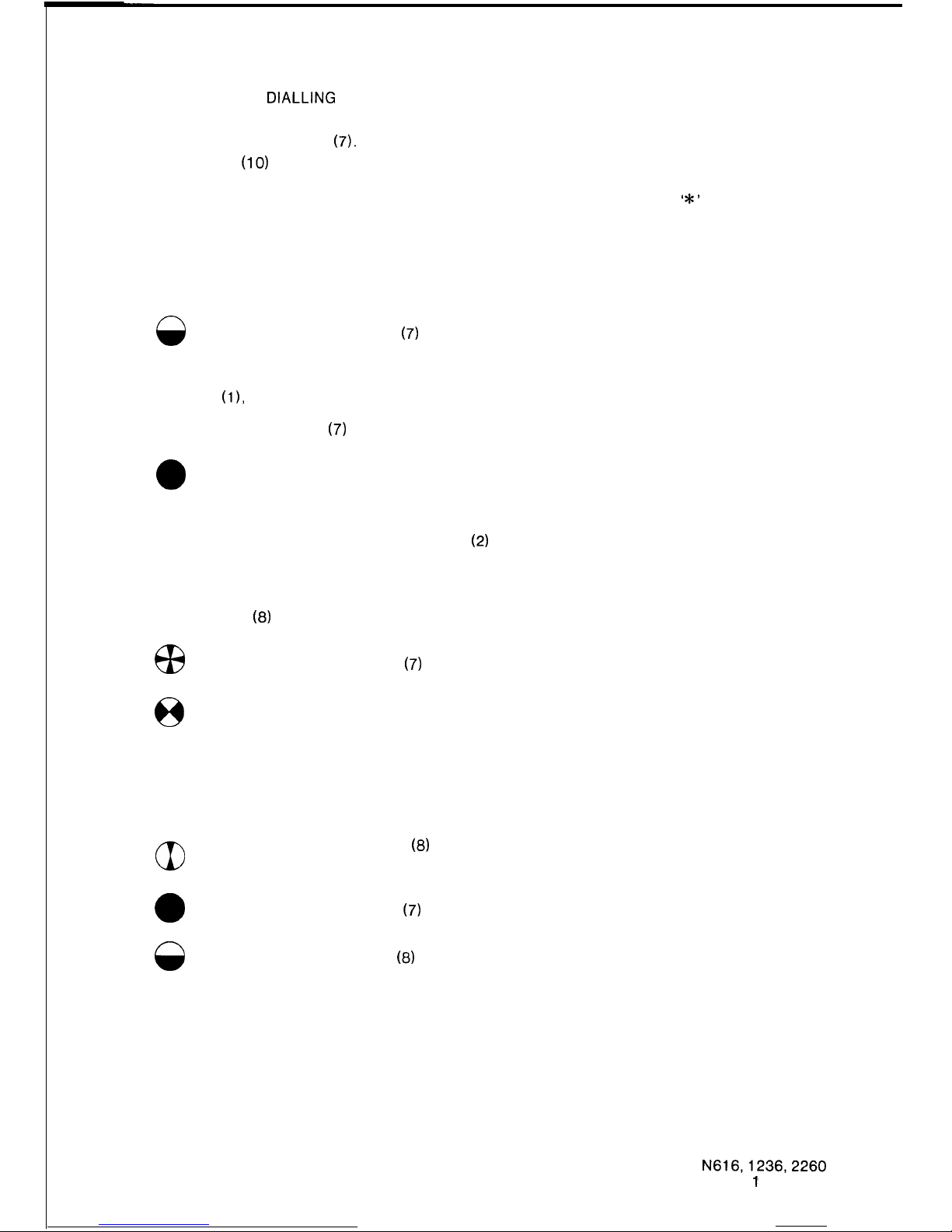
1.3.4 STATION OPERATIONS
PLACING AN EXCHANGE LINE CALL:
Lift the Handset (1) and press a free Exchange Line Key (7).
Dial the desired number after receipt of Dial Tone.
.-
The selected Exchange Line Status LED (7) indicates:
a
Busy condition at all stations.
No other station can come across this line. You have complete privacy.
LAST NUMBER REDIAL:
Lift the Handset (1).
Select a free Exchange Line Key (7).
When you hear Dial Tone, press the DC (Dial Control) Key (10) then press the
‘*’
button.
The system automatically dials the last number called. A
pause
a PABX (i.e. if you first
dialled
the digit for an outside line).
is inserted if you
dialled
through
ON-HOOK DIALLING:
To initiate a call without lifting the Handset (1);
-
Press the MON Key (1
l),
Select a free Exchange Line Key (7) and dial the required number.
Once the person being called answers the telephone, you must lift the Handset (1) off-hook to
speak.
ABBREVIATED DIALLING:
STORING TELEPHONE NUMBERS
Lift the Handset (1).
Press the DC Key (10) and wait for Dial Tone.
a
The ICM Status LED (13) will light.
Assign the storage location by dialling a number from 10 to 25.
Then dial the desired telephone number. If a pause is required within the telephone number
press the
“#‘I
button and continue entering the remaining digits.
Up to 16 digits may be stored including any pause.
To store further abbreviated dialling telephone numbers, press the DC Key (10) and repeat the
above procedure. Place the Handset (1) on-hook when you have finished.
N616,1236,2260
11
ISSUE 1
USING ABBREVIATED DIALLING
Lift the Handset (1).
Select a free Exchange Line Key
(7).
Press the DC Key
(10)
and dial the abbreviated number (from 10 to 25) corresponding to the
telephone number you wish to dial.
When dialling stops due to a pause, wait for the new dial tone, then press the
‘*’
button to
continue dialling the abbreviated number.
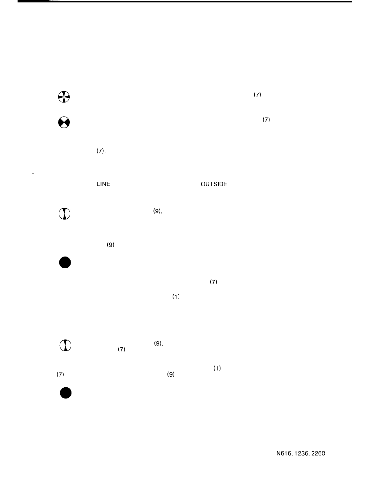
ANSWERING AN EXCHANGE LINE CALL:
Incoming calls are signalled by a Tone Caller (if assigned) through the Station Speaker (2) and
the
0
Exchange Line Status LED
(7)
slow flashes at all stations.
To answer the call,
Lift the Handset
(11,
Press the Exchange Line Key (7).
The Exchange Line Status LED
(7)
then indicates:
0
Busy condition at all stations,
Should an exchange line call come for your station while it is in the busy condition, off-hook ring
signalling will be heard through the Station Speaker
(2)
if this option is assigned.
Once the call is answered, no other station can come across the line.
HOLDING AN EXCHANGE LINE:
Press the HOLD Key
(6)
once. The
a3
Exchange Line Status LED
(7)
on your station will indicate
8
HOLD condition is indicated on all other stations.
If provided, music is transmitted to the held line.
I-HOLD.
To release the exchange line from Hold, any station may press the Exchange Line Key (7)
corresponding to the held line.
aI
Pressing the “HOLD” Key
(6)
twice puts the exchange line on EXCLUSIVE
HOLD. In this condition only the station which held the line may answer the line.
0
Exchange Line Status LED
(7)
indicates busy at all other stations.
8
The LED in the HOLD Key
03)
may indicate Message Waiting.
AUTOMATIC RING BACK (PROGRAMMABLE OPTION):
Once an exchange line has been on Exclusive Hold for a preset time, the Tone Caller signals
again. If the call is not answered after a further 20 seconds the DSS station will ring.
12
N616,1236,2260
ISSUE
1’
TRANSFERRING AN EXCHANGE LINE CALL:
Vocal Transfer
Hold the Exchange Line and advise the required person to pick-up the call.
Transfer by Intercom or Paging Call
Place the call on hold and inform the required person via an intercom or paging call as
described in Placing an Intercom Call and Paging.
I-HOLD is indicated on the held Exchange Line Status LED
(7)
at the holding
station and the
0
HOLD condition is indicated on the Exchange Line Status LED
(7)
at all other
stations.
The transferred call is answered by lifting the Handset (1) and pressing the corresponding
Exchange Line Key
(7).
-
MULTI PARTY CONFERENCE (EXCHANGE LINE):
Two EXCHANGE LINE CONFERENCE (SIMULTANEOUS OUTSIDE LINE CALLS)
While talking on an exchange line call,
Press the ADD ON Key
(9),
the exchange line is held and the Exchange Line
Status LED (7) indicates Add On Standby.
Place another call using a free exchange line and begin the conversation.
Press the ADD ON Key
(9)
again to begin the conference.
0
Both Exchange Line Status Lamps (7) indicate busy.
To release one exchange line press the Exchange Line Key
(7)
corresponding to the person to
whom you wish to continue to converse.
To terminate the conference place the Handset
(1)
on-hook.
TWO OR THREE STATION CONFERENCE WITH AN EXCHANGE LINE (OUTSIDE CALL
CONFERENCE)
While talking on an exchange line call,
Press the ADD ON Key
(9),
the exchange line is held and the Exchange Line
Status LED
(7)
indicates Add On Standby.
Ask the desired person, if located nearby, to lift the Handset
(1)
and press the Exchange Line
Key
(7)
you are using. Press the ADD ON Key
(9)
again to begin the conference.
a
The Exchange Line Status LED (7) indicates busy.
13
N616,1236,2260
ISSUE 2

Alternatively, the station which is to join the conference may be called via the intercom.
When the intercom call is answered, ask the person called, to lift the Handset (1) and press the
ICM Key (13) or the Exchange Line Key (7) you are using. Press the ADD ON Key (9) again to
begin the conference.
0
The Exchange Line Status LED (7) will indicate busy.
If the intercom call is not answered, press the ADD ON Key (9) to continue the conversation.
Up to 3 stations can be in conference with an exchange line, each station is added to the
conference using the above procedure.
LISTEN-IN MONITORING:
Once a call is established and you wish to listen-in, but not take part in the conversation.
a
Press the MON Key (11) and then place the Handset (1) on-hook.
The received voice signal will be heard through the Station Speaker (2).
To stop monitoring, press the MON Key (11) again, or lift the Handset (1).
SWITCHHOOK FLASH (PROGRAMMABLE OPTION):
This facility is provided only when the system is connected to a PABX which uses Voice
Frequency dialling.
While on a local call via the PABX press the Switchhook Flash Key to hold the exchange line at
the PABX. Operation of the Switchhook Flash Key will give loop break of 1 second.
The Switchhook Flash Key is allocated as follows:
616 Exchange Line 6
1236
Exchange Line 12
2260 Exchange Line 22.
EARTH RECALL (SYSTEM OPTION):
This facility is provided only when the system is connected to a PABX which uses decadic
dialling.
While on a local call via a PABX press the RECALL Key to hold the exchange line at the PABX.
Operation of the Recall Key will put an earth on the line for 1 second.
In some cases the RECALL Key may be used to call the PABX operator.
The RECALL Key is allocated as follows:
616 Exchange Line 6
1236 Exchange Line 12
2260
Exchange Line 22.
EXCLUSIVE LINE (SYSTEM OPTION):
Only one station is connected to an Exclusive Line. Operation of an Exclusive Line is the same
as the operation of an exchange line, as described above.
The exceptions being; an Exclusive Line can not be transferred and access barring is not
applied to an Exclusive Line.
An Exclusive Line may be one of the last three Exchange Line Keys (7).
14
N616,1236,2260
ISSUE 2
HOT LINE
CALL(SYSTEM
OPTION):
Only two stations are connected to a Hot Line.
To call the other station,
Lift the Handset
(l),
and press the Hot Line Key.
0
The Hot Line Status LED indicates busy.
To answer a Hot Line call, the
a3
Hot Line Status LED indicates a call.
Lift the Handset
(l),
and press the Hot Line Key.
0
The Hot Line Status LED indicates busy.
Hot Lines cannot take part in a conference.
A Hot Line may be one of the last two Exchange Line Keys
(7).
PRESELECTION:
A key may be operated up to 5 seconds before lifting the handset to seize a line.
PLACING AN INTERCOM CALL:
Check that the Intercom Status LED (13) is not on, since this indicates that all intercom links are
busy.
Lift the Handset
(1).
0
Press the ICM Key (13).
Wait for Intercom Dial Tone (constant tone).
Dial the desired station’s number.
A Single Tone Burst indicates you can converse with the person at that station. Your voice will
be heard through the Station Speaker
(2),
“Handsfree Talkback”.
A Double Tone Burst indicates that the station being called has the microphone switched off.
Therefore, you will not hear the person being called unless the microphone is switched on or the
ICM Key
(13)
is operated and the Handset
(1)
is used.
A Slow Repeating Tone indicates that the station is busy on another call.
A Fast Repeating Tone indicates that the station called is in the Do Not Disturb mode.
Another station can not listen-in on your call, complete privacy.
To call a DSS Console Attendant, carry out the above procedure and dial
“0”
for the first DSS
Console or “9” for the second DSS Console instead of the station number.
SIGNAL CALL:
When placing an intercom call to another station, and there is no immediate response, the
person at the calling station may choose to initiate a signal call by dialling any extra digit.
This action changes the signalling at the called station from voice signalling, “Handsfree
Talkback”, to audible signalling until the call is answered or the calling party hangs-up. The
calling party will hear ring tone through the Handset (1) while the called station is transmitting
audible signalling.
A Signal Call is answered by lifting the Handset (I) and pressing the ICM Key (13).
N616,1236,2260
15
ISSUE 1
ANSWERING AN INTERCOM CALL:
A Single Tone Burst from the Station Speaker
(2)
signals an intercom call.
The originator of the call can be heard via the Station Speaker
(2),
“Voice Calling”.
The Intercom Status LED (13) will indicate;
6x3
Microphone-on, or
A
Microphone-off.
When the microphone is on, you can
“talk back” without lifting the handset, “Handsfree
Tal
kback”
If the microphone is off, press the DND Key (12) to turn the microphone on.
The DND Key
(12)
may be pressed during the call to turn off the microphone, another operation
of the DND Key (12) is required to turn the microphone on, again.
At anytime during the call, the Handset
(1)
can be used.
Lift the Handset (1) and press the ICM Key (13).
0
The Intercom Status LED
(13)
will indicate busy.
ALTERNATE POINT ANSWERING
To answer an intercom call being made to another station located nearby.
Lift the Handset
(1).
Dial the number of the station being called. Do not press the Intercom Key during this operation.
a
The Intercom Status LED (13) will indicate busy.
CALL TO A DSS CONSOLE ATTENDANT:
Lift the Handset
(1).
0
Press the ICM Key (13).
Wait for Intercom Dial Tone.
Dial
“0” for the first DSS Console or
“9” for the second DSS Console.
THREE STATION INTERCOM CONFERENCE:
Place an intercom call to the first station and ensure that the called party answers using the
Handset
(1).
Press the ADD ON Key
(9).
Wait for Intercom Dial Tone.
Call the second station and ensure that the called party answers using the Handset
(1).
Press the ADD ON Key
(9)
again and the conference is set up.
If one party places the Handset
(1)
on-hook, the conversation may continue between the
remaining parties.
I
16
N616,1236,2260
ISSUE 1
,-
_-
DO NOT DISTURB (PROGRAMMABLE OPTION):
This facility is a programmable option and may not be allocated to all stations.
A single operation of the DND Key (12), while the handset is on-hook, puts the station into Do
Not Disturb mode
0
The DND Status LED
(12)
indicates Do Not Disturb busy.
To remove the Do Not Disturb condition operate the DND Key
(12)
twice.
0
The DND LED (12), then indicates the free condition
The DSS Station may override the Do Not Disturb condition depending on how the system is
programmed.
CALL FORWARDING (PROGRAMMABLE OPTION):
To automatically transfer Intercom and Exclusive Line calls to a preassigned station.
Press the DND Key (12).
0
Do Not Disturb Status LED
(12)
indicates busy.
Exclusive Line calls and Intercom calls will be automatically directed to the preassigned station.
Press the DND Key (12), twice to reset Call Forwarding.
0
Do Not Disturb Status LED
(12)
indicates the free condition.
MICROPHONE CUT-OFF:
To cut-off the microphone, while using “Handsfree Talkback” on an intercom call, press the
DND Key (12). For stations programmed to have Do Not Disturb the DND Key
(12)
must be
pressed twice. However, stations with an intercom call in progress, only require a single
operation of the DND Key
(12)
to cut-off the microphone.
8
The DND Status LED
(12)
indicates Microphone Cut-off.
While in the Microphone Cut-off state the calling party can not hear any conversation at the
called station.
A station in the Microphone Cut-off state can receive incoming intercom calls but “Handsfree
Talkback” is inhibited.
A single operation of the DND Key
(12)
returns the microphone to its normal condition.
0
The DND Status LED
(12)
indicates the free condition.
N616,1236,2260
17
ISSUE 1’
PAGING:
Three types of paging calls may be made.
1.
ALL CALL PAGING
This method is used to make an announcement over the Station Speaker
(2)
of all stations
and through the external loudspeakers, if equipped.
2.
INTERNAL ZONE PAGING (PROGRAMMABLE OPTION)
This method is used to make an announcement through the Station Speaker
(2)
of the
stations included in one of four zones. When the system is installed the stations are
programmed into one of the four zones.
3.
EXTERNAL ZONE PAGING (SYSTEM OPTION)
This method is used when an external public address or loudspeaker paging system is
connected to the system.
To originate a paging call.
Lift the Handset
(1).
0
Press the ICM Key (13).
Wait for Intercom Dial Tone.
Dial the desired paging number, hear single warbling tone and make the announcement. Busy
stations will not hear the paging announcement.
The paging numbers are as follows:
80
. . . . . All Call Paging
ai
. . . . . Internal Zone
1
a2
. . . . . Internal Zone 2
a3 . . . . .
Internal Zone 3
a4
. . . . . Internal Zone 4
65 . . . . . External Zone 1
*a6 . . . . .
External Zone 2
l Note:
ExternalZone
2 is notprovidedin the 616system.
MEET ME ANSWER PAGING (PROGRAMMABLE OPTION):
Make an All Call or Internal Zone Paging announcement for someone to “Meet Me”.
The originator of the call depresses the
‘*’
button and waits for a response.
To respond to a “Meet Me Answer Paging” call, the respondent lifts the Handset
(1)
of a station
through which the paging announcement was heard, and dials
“6”
to speak to the originator.
MESSAGE WAITING:
When a DSS console attendant activates the Message Waiting facility.
8
The Hold LED
(6)
indicates Message Waiting.
The message may be obtained by pressing the ICM Key (13), and dialling “1”.
Then ask the attendant for the message.
When the call has been answered.
-
0
The Hold LED
(8)
will indicate idle.
ia
N616,1236,2260
ISSUE 1
BACKGROUND MUSIC CONTROL:
When the Handset
(1)
is on-hook the
‘I#”
button is used to turn the Background Music on and off
-
by alternate depressions.
The volume of the Background Music is regulated by the volume control at each station.
POWER FAILURE:
During power failure the exchange lines are automatically switched through to preassigned
powerfail stations. In this condition incoming calls may be received or outgoing calls can be
originated, all other facilities are inoperative.
To answer an incoming call, lift the Handset
(1).
To place an outgoing call, lift the Handset
(11,
wait for exchange dial tone and dial the desired
number.
If a short interruption of the mains power occurs, the operation of the system will be interrupted
and all calls will be cut off.
In this case the red reset LED
(RL
LED) on the power supply will be on. Press the reset switch
(RS
switch) to extinguish the LED. Normal operation will resume if power is still available.
N616,1236,2260
19
ISSUE 1
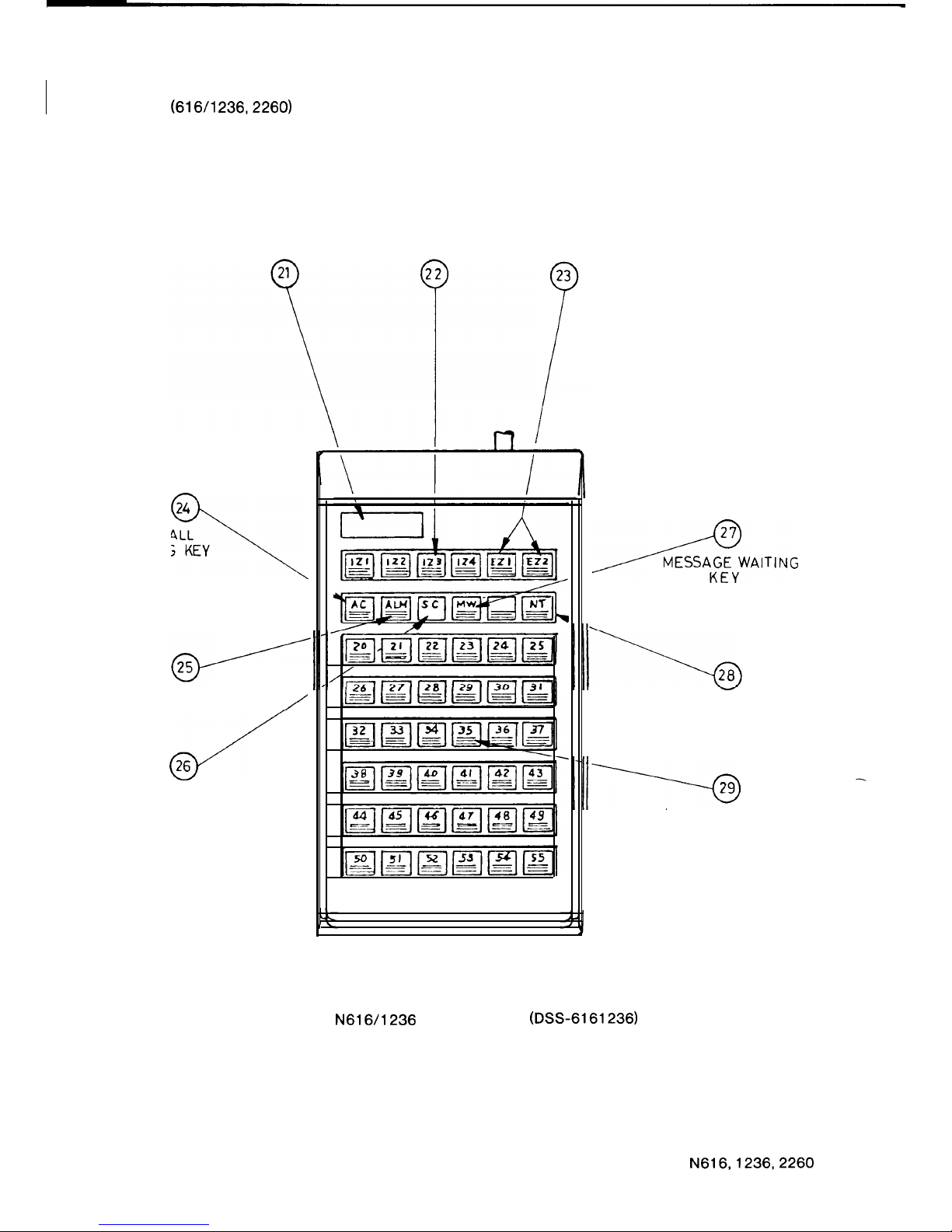
1.3.5
DSS CONSOLE NOMENCLATURE
(616/l 236,226O)
4 DIGIT
INTERNAL ZONE
EXTERNAL ZONE
DISPLAY
PAGING KEYS
PAGING KEYS
24
ALL CALL
3
PAGING KEY
ALARM LED
/
4
26
SIGNAL CALL KEY
AWAITING
NIGHT TRANSFER
KEY
DIRECT STATION
SELECTION KEYS
FIGURE 5
N616/1236
DSS CONSOLE
(DSS-6161236)
20
N616,1236,2260
ISSUE 1
I
-
L
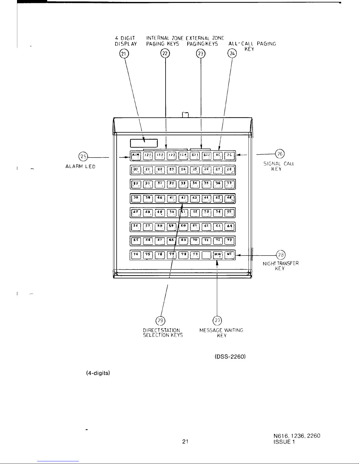
DIGIT INTtRNAl ZONE EXTERNAL ZONE
DISPLAY
PAGING
KEYS PAGING
KEYS
AL
L-CALL
PAGING
KEY
@-
ALARM LED
I
-
DIRECT
STATION
MESSAGE
WAITING
SELECTION
KEYS
KEY
FIGURE 6 N2260 DSS CONSOLE (DSS-2260)
21.
Display
(4-digits)
22.
Internal Zone Paging Keys
23.
External Zone Paging Keys
24.
All Call Paging Key
25.
Alarm Lamp
26.
Signal Call Key
27.
Message Waiting Key
28.
Night Transfer Key
29.
Direct Station Selection Keys including Busy Lamp Field
----a
SIGNAL CALL
KEY
NIGHT TRANSFER
KEY
DSS Station - the station located beside the DSS Console.
21
N616,1236.2260
ISSUE 1
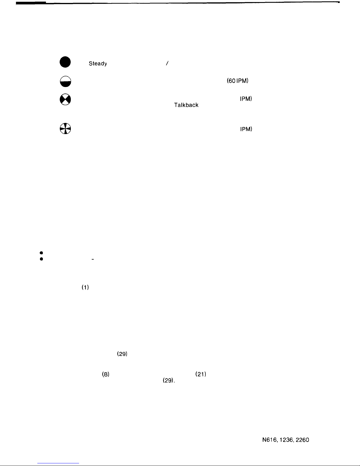
1.3.6
DSS CONSOLE LED INDICATIONS
The Busy Lamp Field shows station status
Off Hook / Busy Condition
0
Slow Flash
Message Waiting
Battery Low
(60
IPM)
8
Flash
Station receiving a
(120
IPM)
Handsfree
Talkback
Intercom
Call
Rapid Flash
Do Not Disturb
Alarm
(300
IPM)
1.3.7
DSS CONSOLE OPERATIONS
SUMMARY
DSS Cal I
Automatic Exchange Line Hold
Digits Display
DSS Override
Signal Call
Automatic Ring Back
Message Waiting
Night Transfer
Alarm Indication
Battery Low Condition
DSS CALL
A DSS Call may be one of the following;
a
Intercom Call
0
Paging Call
-
All Call Paging
Internal Zone Paging
External Zone Paging.
To make a DSS Call.
Lift the Handset
(1)
at the DSS Station.
Press the single function key (22, 23, 24, 29) corresponding to the type and destination of the
call you wish to make.
Automatically the Intercom or Paging Call will be established.
NOTE:
A DSS Console cannot take part or set-up a conference using the ADD ON facility. A
conference must be set-up from the DSS station, only.
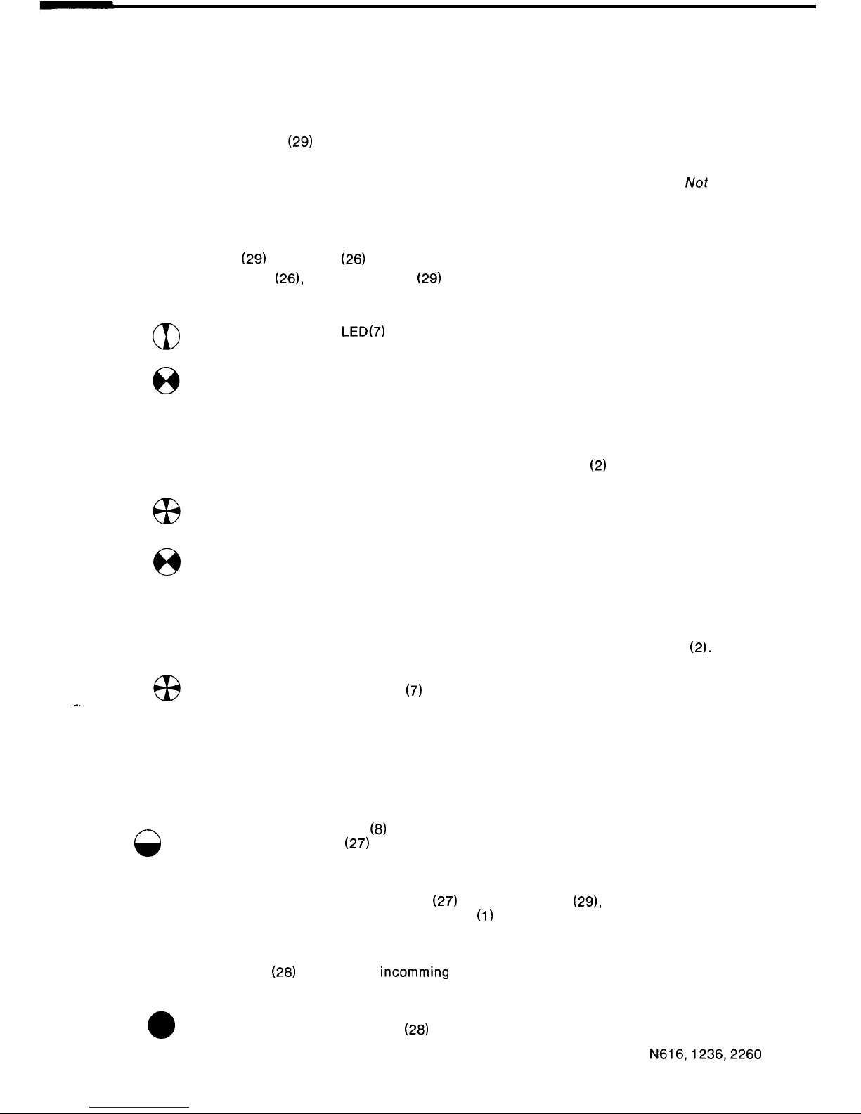
AUTOMATIC EXCHANGE LINE HOLD:
When the attendant at a DSS Console answers an exchange line call, the call may be
transferred using a DSS Key
(29)
or by initiating a paging call using the DSS Console’s special
function keys (22, 23, 24).
This action automatically places the exchange line on hold. Therefore, it is not necessary to
operate the HOLD Key
(8)
at the DSS Station. The Display
(21)
will show the call is held by the
station corresponding to the operated DSS Key (29).
DIGITS DISPLAY:
The two digits on the left side of the display show the number of the held exchange lines and the
two digits on the right side of the display shows the number of the station which holds the
exchange line.
22
N616,1236,2260
ISSUE 1
DSS OVERRIDE:
Calls from the DSS Console have priority over Intercom Calls and Paging Calls.
When the DSS Console overrides a call, the originator of the call will hear DSS Intrusion Tone. A
flashing LED in the DSS Key
(29)
indicates that a call may be overriden.
DSS Console priority over Do Not Disturb is a programmable option.
NOTE
A DSS Console can not override a remote or internal extension which is on Do
Not
Disturb.
SIGNAL CALL:
When a DSS Console attendant does not receive a response after transferring an exchange line
call using a DSS Key
(29)
the SC Key
(26)
may be used.
Operation of the SC Key (26), after a DSS Key
(29)
has been depressed, will cause Audible
Signalling to be transmitted through the Station Speaker at the station to which the call has
been transferred.
aI
The Exchange Line LED(7) will indicate Exclusive Hold at the station to
which the call has been transferred.
And Hold at all other stations.
Audible Signalling will be transmitted to the station for 20 seconds.
If the call is not answered within 20 seconds it will be directed back to the DSS Console.
Audible Signalling will be transmitted from the DSS Station Speaker
(2)
until the call is
re-answered.
The Exchange Line Status LED (7) will indicate I-Hold condition at the DSS
station, and the station to which the call has been transferred.
8
And hold condition at all other stations.
AUTOMATIC RING BACK:
If exchange line calls transferred from the DSS Console are not re-answered within the
preprogrammed ring back time, Audible Signalling will be heard via the DSS Station Speaker
(2).
-.
The Exchange Line Status LED
(7)
will indicate the I-HOLD condition.
MESSAGE WAITING:
To indicate to a station that there is a message at the DSS Console, carry out the following
procedure.
After pressing the desired DSS Key (29).
Press the MW Key (27).
8
The Message Waiting LED
(8)
(Hold LED) at the unattended Station and the
corresponding DSS LED
(27)
on the DSS Console will indicate Message Waiting
active.
The Message Waiting condition will clear when there is a call from the associated station or if
the DSS Console attendant operates the MW Key
(27)
and the DSS Key (29), corresponding to
the station where the message was left, while the Handset
(1)
is on-hook.
NIGHT TRANSFER:
Operation of the NT Key
(28)
will direct all
incomming
audible signals to the programmed Night
Transfer Station.
a
The Night Transfer Status LED
(28)
will indicate active.
N616,1236,2260
23
ISSUE 2
ALARM INDICATION:
When the external alarm signal is detected (option), Alarm Tone will be heard at the DSS Station.
G3
The Alarm Status LED
(25)
will indicate an Alarm.
The condition is stopped when the alarm signal is cleared.
BATTERY LOW CONDITION:
8
The Alarm Status LED
(25)
indicates the Battery Low Condition.
If the battery is not replaced in a short time the system will
malfunction.
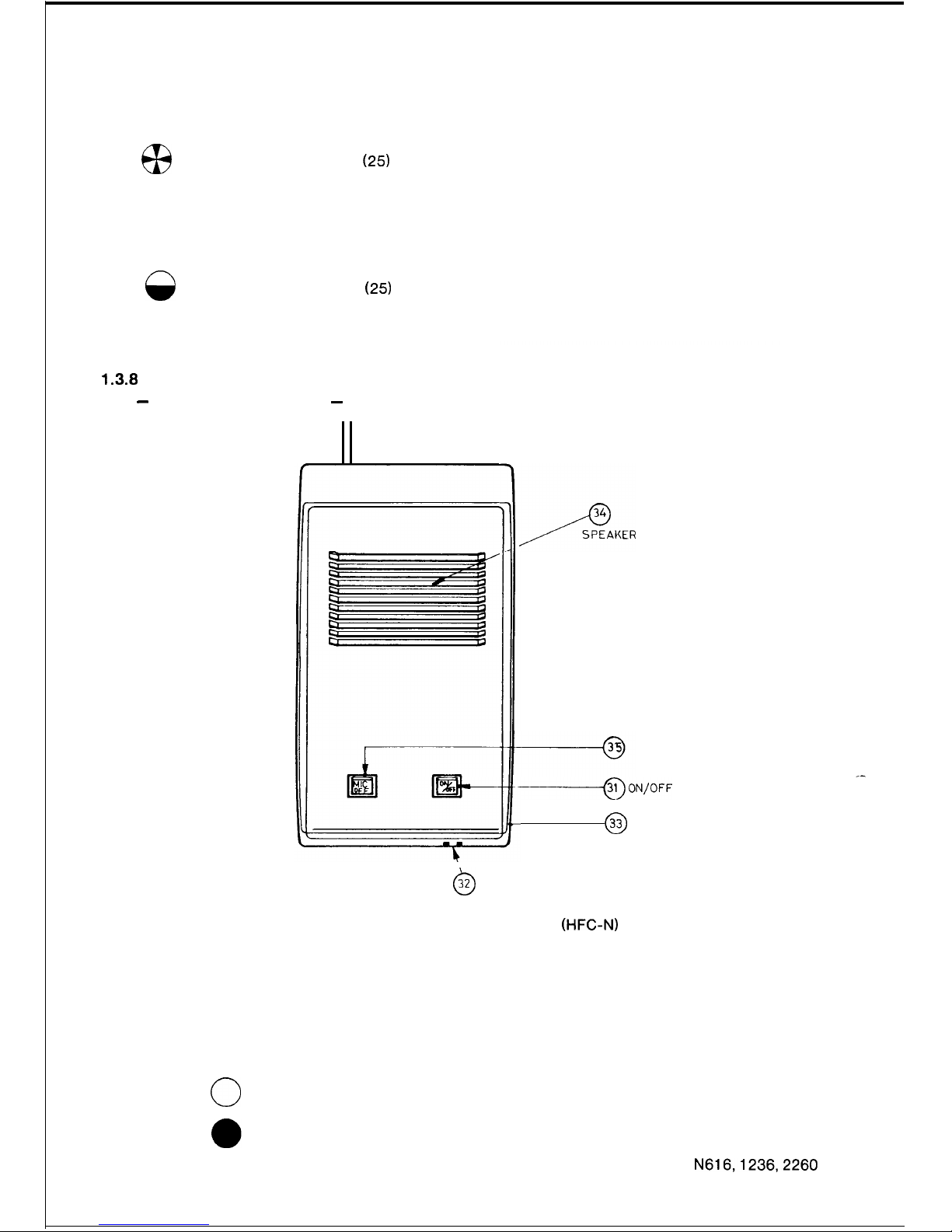
1.3.6
OPTIONAL EQUIPMENT
-
HANDSFREE CONSOLE
-
MICROPHONE
CUT- OFF KEY
--ON/OFF
KEY
0
33
VOLUME CONTROL
0
32
MICROPHONE
FIGURE 7 HANDSFREE CONSOLE (HFC-N)
Nomenclature
31. On/Off Key and LED
32. Microphone
33. Volume Control
34. Speaker
35. Microphone Off Key and LED
Lamp Indications
0
Off Non-operational State
On
Active Handsfree Condition
Microphone Off Condition
24
N616,1236,2260
ISSUE 2
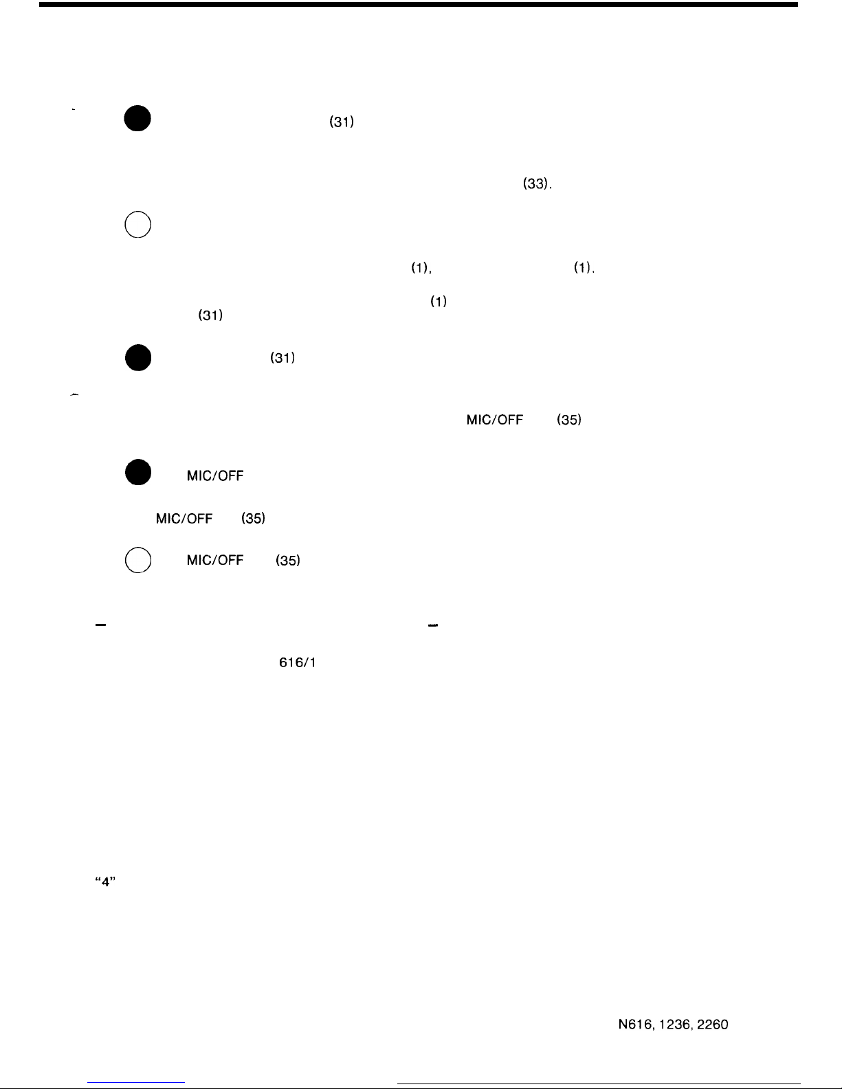
Operation
.
Press the ON/OFF Key
(31)
to activate the Handsfree condition.
Select the required system feature using appropriate station key.
If necessary adjust the speaker volume level using the Volume Control (33).
0
Press the ON/OFF Key (31) again to terminate the call.
To transfer the conversation to the station Handset
(11,
simply lift the Handset
(1).
The ON/OFF
LED (31) will go off automatically.
To transfer the conversation from the station Handset
(1)
to the Handsfree Console, first press
the ON/OFF Key
(31)
and the
0
ON/OFF LED
(31)
will come on.
-
Now, place the Handset (1) on-hook.
To prevent your speech being transmitted, press the
MIC/OFF
Key
(35)
to turn off the
microphone, the
0
MIC/OFF
LED (35) will come on.
Press the
MIC/OFF
Key
(35)
again, to turn the microphone on. The
0
MICYOFF
LED
(35)
will go off
-
INTERNAL EXTENSIONS (INTERNAL STATIONS)
-
Nomenclature
Key Stations:
616/l
23612260 stations shown in the front of the instructions
(fig. 1, 2 8 3).
Internal Extensions:
Telecom Touchfone 10 or rotary dial telephones with decadic
dialling.
Internal Extensions are normally located in the same premises as the system and are restricted
in their use of system facilities.
For Internal Extensions with intercom access only, refer to the operating instructions for
Remote Extensions.
+ EXCHANGE LINE CALLS
Placing an Exchange Line Call :
Lift the Handset. Wait for Internal Dial Tone.
Dial “3” to allocate any free Exchange Line for your call or,
“4”
to allocate a free Exchange Line from the second group when the exchange lines are
grouped.
Dial the desired number after the Exchange Line Dial Tone has been connected.
N616,1236,2260
25
ISSUE 2

Answering an Exchange Line Call :
There is no facility to directly answer an Exchange Line Call. Exchange line calls must be
transferred to an Internal Extension using the ADD ON Conference facility at a Key Station, or by
a signal call from a DSS Console.
Transferring an Exchange Line Call :
An Exchange Line Call transferred to an Internal Extension can be transferred to a Key Station
or Internal Extensions as follows:
Depress the Switchhook momentarily while talking on an Exchange Line Call. This operation
will put the Exchange Line on Add On Standby. The Exchange Line Key
(7)
on Key Stations will
indicate Busy.
Wait for
Internal
Dial Tone. If dial tone is not received, depress the Switchhook again and the
Exchange Line is returned to you. Repeat the above operation if necessary.
Dial the Station to which the Exchange Line is to be transferred using an Intercom Call.
Ensure that the person being called answers using the Handset.
Depress the Switchhook again and a conference is set-up between three parties. Place your
Handset on-hook and the connection between the two remaining parties is maintained.
+ INTERCOM CALLS
Placing an Intercom Call :
Lift the Handset. Listen for Internal Dial Tone.
Then dial
“2”
and the number of the required Key Station or Internal Extension.
If the call is for another Internal Extension, Ring Tone or Busy Tone is heard in the receiver. Wait
for the called party to answer.
If the call is for a Key Station, and the station is not busy, Single or Double Tone Burst is heard
and a normal “Handsfree Talkback” call is initiated.
Answering an Intercom Call :
Incoming calls are announced when the telephone rings.
Lift the Handset to answer.
Three-party Intercom Conference
A three-party intercom conference may be set-up as described for transferring an exchange
line call, above.
+ PAGING
Lift the Handset.
Wait for Internal Dial Tone.
Dial the desired paging number for
All Call Paging
80
Internal Zone Paging
81 -84
External Zone Paging
85 or 88’
*
86 is not provided in the 616 system.
+ CALL TO A DSS CONSOLE ATTENDANT
Lift the Handset.
Wait for Internal Dial Tone.
Dial
“0”
for the first DSS Console or
“9” for the second DSS Console.
26
N616,1236,2260
ISSUE 2
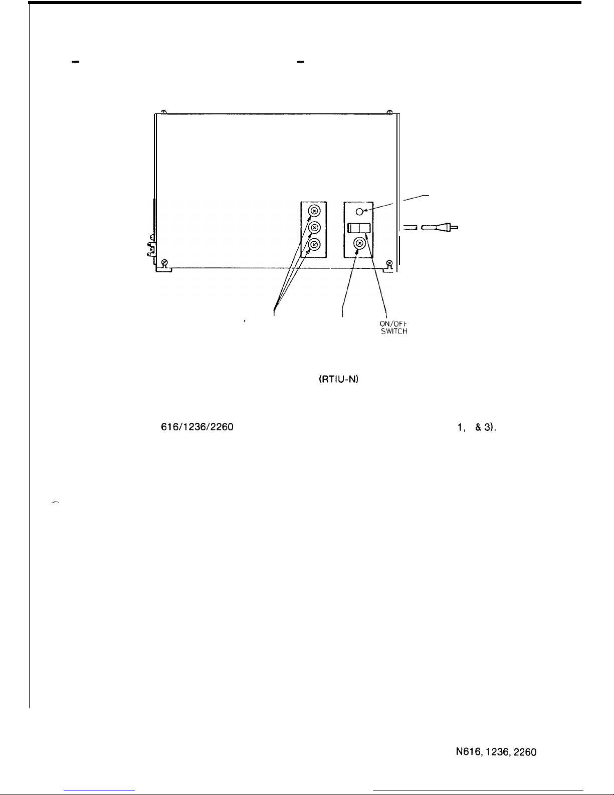
-
REMOTE EXTENSIONS (REMOTE STATIONS)
-
/
POWER ON
LAMP
POWER SUP PLY
MAINS
FUSES
FUSE
FIGURE 8 REMOTE EXTENSION AND TIE LINE
INTERFACE UNIT (RTIU-N)
Nomenclature
Key Stations:
616/l 236/2260
stations shown in the front of the instructions (fig. 1, 2 8.3).
Remote Extension:
Telecom Touchfone 10 or rotary dial telephones with decadic dialling.
Remote Extensions are located in premises remote from the system and are restricted in their
use of system facilities.
+ EXCHANGE LINE CALLS
-
Placing an Exchange Line Call :
Call a Key Station.
Ask that person to connect an exchange line to your telephone using the ADD ON Conference
facility.
Dial the desired number after Exchange Line Dial Tone has been connected.
Answering an Exchange Line Call :
There is no facility to directly answer an Exchange Line Call. Exchange line calls must be
transferred to a Remote Extension using the ADD ON Conference facility at a Key Station.
Transferring an Exchange Line Call :
An Exchange Line Call transferred to a Remote Extension can be transferred to a Key Station,
Internal Extension or Remote Extension as follows:
Depress the Switchhook momentarily while talking on an Exchange Line Call. This operation
will put the Exchange Line on Add On Standby.
N616,1236,2260
27 ISSUE 2
 Loading...