

Page 1
TELECOM
INSTRUCTION
C
MAru<ETING
3
Internal
B2009
INSTALLATION
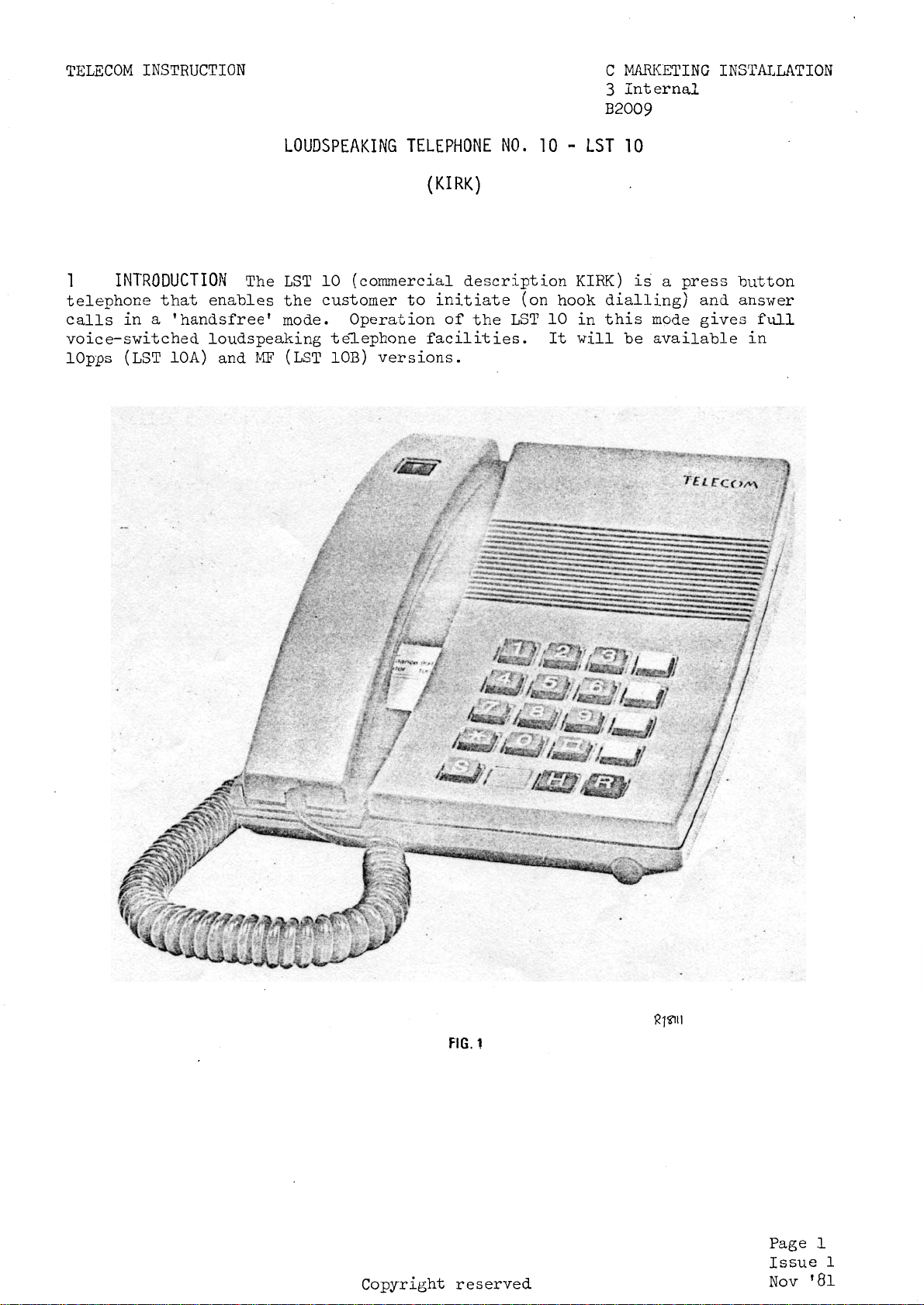
1
telephone
calls
voice-switched
lOpps
INTRODUCTION
that
in a 'handsfree'
(LST
lOA)
LOUDSPEAKING
The
LST
enables
loudspeaking
and
MF
the
mode.
(LST
TELEPHONE
10
(commercial
customer
Operation
te~ephone
lOB)
to
versions.
(KIRK)
description
initiate
of
the
facilities.
NO.
10 -LST
(on
LST
hook
10
It
KIRK)
dialling)
in
this
will
10
is a press
mode
be
available
and
gives
button
ansi-rer
full
in
Copyright
FJG.1
reserved
~1~11
Page
Issue
Nov
1
1
'81
Page 2
TEI£COM
INSTRUCTION
C3
B2009
2
1.
5 Kgs.
line
DESCRIPTION
2.1 The
It
is
cord
The
LST
(iii)
2. 2
~
LST
available
which
10
(i)
(ii)
Keypad
-
is 2 metres
can
as a normal
for
as a 'handfree'
switches
10
meas.ures 225
1n
s1x
be
used
listening-in
The
keypad
the
mm
different
1n
length.
1n
three
telephone
only
loudspeaking
contains
loudspeaker
long,
different
(eg
case
Recorded
the
normal
ON
180
colours
mm
wide
and
ways:-
Announcements)
telephone
0 -G
and
OFF
and
90
lS
supplied
with a built
keys
(listening
mm
1n
high
with
1n
for
only)
and
weighs
a 3 w1re
microphone.
dialling,
2.3 Handset The
of
both
When
knob
upwards,
privacy.
2.4 Toneringer
four
different
a
switch
G -
~
switches
-
Recall
if
0 0 G ! D
!ttl
the
on
handset
the
the
and
G
handset
the
microphone
tone
underside
may
handset
and
the
is
Incoming
combinations
the
microphone ( in
telephone
llttl
held
of
and
be
used
contains
loudspeaker.
or
placed
is
automatically
calls
that
the
telephone
used
G
on
are
in
the
a volume
horizontally,
are
indicated
can
base
PBX
MF
be
instrument.
unit)
exchange
not
used
vers1on.
control
switched
selected
by
ON
/OFF ( hands£ree)
on
the
lOpps
which
with
off,
the
by
using a small
adjusts
the
volume
giving
loudspeaker.
verslon.
the
control
the
customer
There
coin
volume
are
to
set
2.5 Telephone
type
under
It
connected
3
and
the
FIELD
should
is
situated
handset.
OF
USE
be
noted,
to
any
The
plan
Number
in
the
LST
at
this
numbers.
Label
clear
10
can
point
The number
plastic
be
connected
1n
time,
label
label
that
holder
to
DEL
the
is
LST
an
'Ambassador'
fotmd
or
direct
10
is
on
not
the
base
PBX
extensions.
suitable
telephone
unit
to
Page
Issue
Nov
be
2
1
'81
Page 3

TELECOM
The
if
wired
INSTRUCTION
LST
10
can
as
an
external
only
be
connected
extension
to
PMBX
using a UAA
2/,
99.
3/
and
4/
switchboard
C3
B2009
extensions
4
OPERATION
To
make a
a
normal
To
make a
Handsfree.
Answering a call.
call
telephone.
call
The method
-
as
-
of
operating
Lift
of
knob
Press
torre
Red
the
Call
Volume
rotary
The
handset
locking
handset
the
receiver
in
and
will
(To
lock
LED
base
number
of
control
call
(handsfree
~s
and
the
handset.
lock
be
heard.
key:-
flashes
unit
required.
the
can
be
or
by
both
the
mode).
as
follows:-
call
can
0
press
to
is
in
loudspeaker
knob
answered
pressing
0
number
be
adjusted
and
the
indicate
the
in
the
and
and
required.
by
0
key
circuit.
either
keys -dial
down
that
can
be
handset.
by
~keys
the
then
the
microphone
varied
lifting
The volume
rotary
forwards)
by
control
the
the
in
Transferring
from
the
Transferring
Terminating
~------------------------~---------------------
5
the
the
base
from
the
the
handset.
INSTALLATION
The
LST
base
and
a
handset
unit.
the
base
a
10
the
unit
call.
call
to
call
to
The
will
handset
LST
be
delivered
will
Press
(Red
~key
By
released
handset.
To
requires
To
'handsfree'
10
and
lock
LED
flashes)
replace
lifting
and
terminate
replacement
terminate
should
be
be
without
protected
the
handset
the
a
call
a
call
mode
installed
base
~
by
and
then
whilst
the
handset.
the
conversation
originated
of
the
originated
release
in
or
handset
clear
~
~
handset.
the
accordance
plastic
keys
still
transferred
by
in
~
covers.
depressing
key
using
key.
with
dust
is
covers.
the
automatically
to
the
the
handset
Diagram
The
N4480,
insides
See
fig
of
2.
Fig 2 follows
Page
Issue
Nov
3
l
'81
Page 4

TELECOM
INSTRUCTION
C3
B2009
FIG.
2
R 1l?!t2..
Page
Issue
Nov
4
1
'81
Page 5

TELECOM
INSTRUCTION
C3
B2009
The
separately
TO
FIT
COVERS
(a)
underside
the
handset
new
covers.
(b)
cover
tighten
the
single
6
that
replaced
into
(c)
two
screw
TESTING
the
appropriate
as
KIT
Remove
of
the
(handset
Fit
Base
the
two
up
the
two
Fit
Handset
slots
unit
completely.
in
to
The
functions
colour
lQlA/Colour.
existing
base
(base
protection).
Cover
slots
screws
Cover
the
top
secure
the
following
correctly.
of
the
dust
Locate
protruding
on-the
end
protectors
protection)
Locate
of
the
handset
tests
base
These
the
underside
cover.
in
and
and
four
from
the
two
handset.
the
If
the
handset
by
loosening
the
screws
lugs
the
base.
of
the
protruding
Lower
table
telephone
single
will
on
the
base
below
cover
the
screw
be
required
top
Lower
to
lugs
the
cover
should
is
faulty
should
two
underside
the
secure
of
be
scre\vs
on
base
the
and
made
it
be
the
to
the
ordered
on
underside
retain
of
the
cover
cover.
cover
tighten
to
ensure
should
the
the
and
into
up
be
of
the
STEP
1
Press
and
keys.
0
2
3
4
5
7
BTHQ/ME/RCS8.2.1
Rotate
Dial
Lift
Replace
test
Handset.
RECOVERY
PROCEDURE
lock
volume
handset.
The
control
centre
following
Loudspeaking
0
number
and
downwards Volume
item
should
Telephone
LED
the
Ring
Test
Call
handset.
Call
be
No.
E N D
recovered
flashes.
loudspeaker.
of
dial
tone
centre
transferred
disconnected.
10
(LST
heard
lOA
INDICATION
Dial
tone
on
answers.
from
and
returned
or
lOB)
tone
loudspeaker
h·2ard
increases.
base
unit
to
the
over
to
stores:-
Page
Issue
Nov
5
1
'81
 Loading...