

Page 1
GSM
Page 1 of 4
GSM
-
Route BRI
Installation and User Guide
Package Contents
The unit will be supplied with:
• GSM-Route BRI
• Power Supply Adapter and cable
• 2 x GSM Antenna for GSM-Route BRI 2
• Unit Fixings
• Fixing Template
• This Installation Guide
• Safety Earth cable, (SEG Safety Earth
Ground)
• 1 x 2 meter RJ45 connection cable
• 1 x RJ45 type serial cable for programming
Notices
Emergency Calling
This GSM Gateway must be used with Customer
Equipment that routes an emergency call to
triple zero (000) via other Network interfaces.
Guarantee
The GSM-Route BRI is supplied with a 1-year
return to base warranty which covers any defect
in manufacturing and design. No other
warranties whatsoever are given. If a faulty unit
is required to be returned within the terms of the
warranty contact your local dealer. TelecomFM
or its agents shall accept no liability for any error
or damages of any kind resulting from the use of
this document or equipment it relates to. No
responsibility is assumed by TFM or its agents
for the use or reliability of the GSM-Route BRI
when used in a situation or with other equipment
not supplied or specified by TFM. The wording
in this document may change from time to time.
Please refer to the web site www.telstrom.net for
the latest release.
Intended Use
The GSM-Route BRI is intended to be
connected to the customer’s ETSI standard basic
rate ISDN terminal equipment (PBX) and
optionally to an ETSI standard basic rate ISDN
network (NTU).
The GSM-Route BRI will auto detect if an ISDN
circuit is present. If GSM-Route BRI detects that
an ISDN circuit is not available, the unit will be
configured for this setting.
The GSM-Route BRI will Auto detect Point to
Point or Point to Multi-Point on connection of an
ISDN circuit.
The GSM-Route BRI will direct outgoing calls
either over the Mobile Network or the ISDN
network according to its configuration. The
configuration it is shipped with is to direct all
mobile prefixes to the GSM network. In order to
change this, refer to the programming section.
Incoming calls from the GSM network will be
directed to the customer’s terminal equipment.
Power Failure
In the event of loss of power to the unit, the
ISDN lines connected through the GSM-Route
BRI, will connect the customer’s terminal
equipment by means of a “Metallic” by-pass
mechanism.
Mobile Signal Failure
In the event of the loss of the GSM network the
unit may be configured to reroute the calls over
ISDN.
ISDN Signal Failure
In the event of disconnection from the ISDN
network, calls which were routed across the
mobile network will continue to do so.
Power Supply
The GSM-Route BRI operates from a nominal
100-240v. AC supply, 47-63 Hz.. The Power
Supply Unit (PSU) supplied with the GSMRoute BRI is fully compliant with: UL1950,
TUV EN60950, BS7002, CSA22.2. Ensure that
you use the power supply reference part no.
KWM24F-OX01, as supplied.
Warning: Do not attempt to work on the
GSM-Route BRI with the mains connected.
Safety Instructions
Failure to follow all instructions may result in
improper operation of the GSM-Route BRI
and/or the risk of electrical shock. All
installation personnel should consult the
information contained in this manual before
attempting to install this product. All installation
engineers should adhere to the following
instructions:
1. The GSM-Route BRI should only be installed
or maintained by qualified PBX personnel.
2. The GSM-Route BRI should only be installed
according to the instructions in this manual.
3. Do not attempt to connect the GSM-Route
BRI whilst the associated PBX is in use.
4. Do not attempt to install the GSM-Route BRI
during an electrical storm.
5. Use caution when installing or modifying
ISDN lines when connecting to the GSMRoute BRI
6. Connect the power supply lead to the GSM-
Route BRI before switching on the power.
(see figure 2)
7. Ensure that the GSM-Route BRI is bonded to
Safety Earth Ground using the earth cable
provided. (see figure 2)
Positioning
Select a suitable location to install the GSM
Route BRI in order
strength
•
on, or near an exterior wall,
•
close to a window
•
on the top floor of the building.
• at
least 1 metre away from other sensitive
electronic equipment.
•
mount antennas vertically with a minimum
distance of 330mm away from each antenna.
(see figure 1)
The signal strength will be degraded if you
install the GSM
•
on walls that contain a large amount of
wiring, steel, or metal construction material.
•
on walls with unusually thick masonry.
•
in metal buildings or in rooms with large
areas of metal.
•
mount the antennae horizontally
You must NOT
•
install your GSM
•
expose the GSM
moisture, i.e.
•
expose the GSM
of heat or cold e.g. air conditioning, heaters or
direct sunlight
•
cover or place obstructions on or around the
unit’s anten
Q
1.
Connect the antennas and insert SIM
cards.
2.
Connect supplied Safety Earth ground
cable.
3.
Power up and wait for unit to initialise.
4.
Connect RJ45 straight through cable from
TE of the unit to the PBX.
refer to other scenarios.
5.
You will hear the unit click and detect its
setup.
6.
LEDs
when PBX is connected.
7.
During initialisation LEDs 18 & 19 will
flash once every 6 seconds while looking
for a GSM base station. After a short
while they will flash according to signal
strength.
8.
Go off hook and access the t
unit. Dial a GSM number (the unit has
been pre programmed with all GSM
prefixes to route via GSM) and you
should hear a tone “Diddley Doo”!
9.
For incoming GSM calls you will need to
setup MSN.
the GSM-Route BRI
-
to optimise the signal
.
,
(see figure 1)
-Route BRI antennae:
-Route BRI outdoors.
-Route BRI to water or
basements or outbuildings.
-Route BRI to direct sources
na(e).
UICK SETUP GUIDE
(Scenario A)
22&23 will flash (75ms/3s on/off)
runk of the
Page 2
GSM
Page 2 of 4
GSM
-
Route BRI
Installation and User Guide
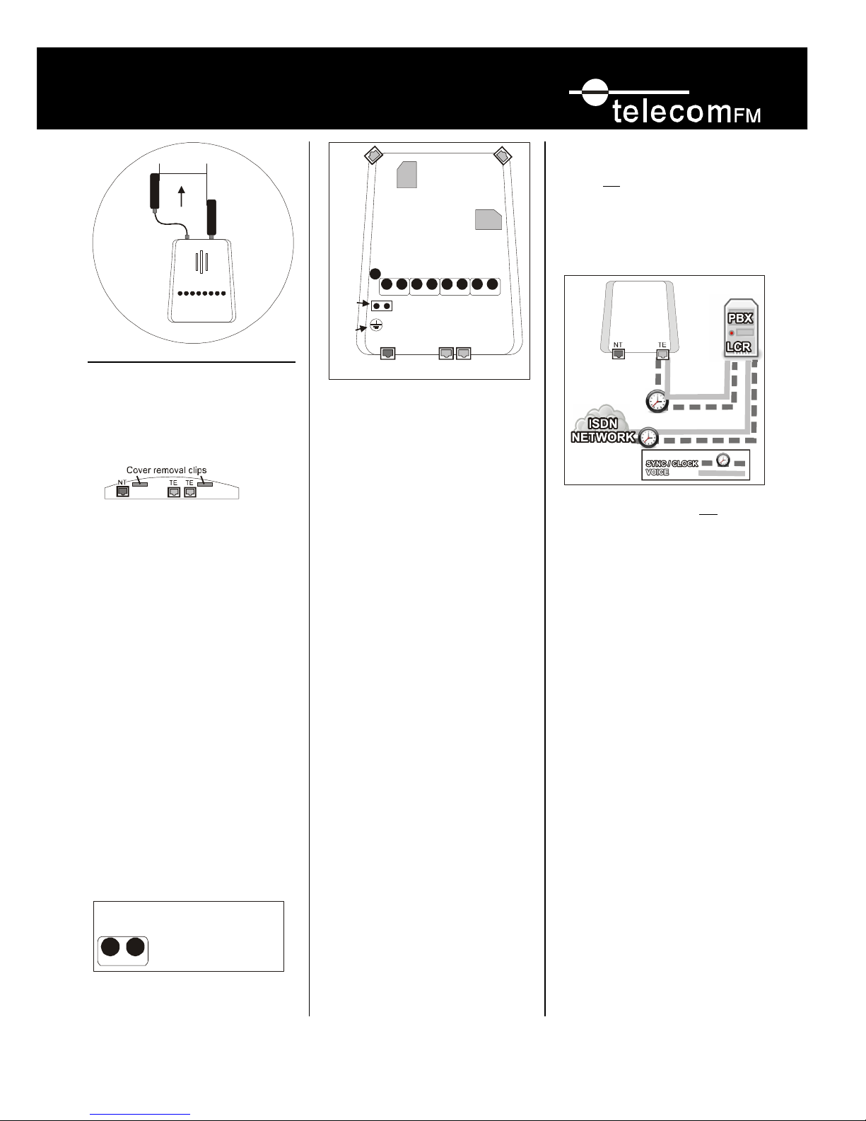
Mounting the GSM-Route BRI
1. Neatly locate and mount the GSM-Route BRI
using the supplied fixing template.
2. Open the cover by pushing the two clips in at
the bottom of the case.
3. Connect the Safety Earth Ground.
4. Connect Antennae(s) (see figure 1)
5. Insert SIM cards into the SIM holders (see
figure 2)
6. Power up the unit. When the power is
connected the amber LED 3 will be lit and the
unit will initialise.
• When the GSM Module(s) are connecting
to a network its status LEDs 24 & 25 will
produce long flashes (600ms/600 ms
On/Off).
• If the GSM module has no SIM card
inserted its status LEDs 24 or 25 will flash
‘SOS’ on its associated LED.
• When a GSM module has logged onto a
network its status LEDs 24 & 25 will
produce short flashes (75ms/3s On/Off).
(refer to figure 3)
• The signal strength on Module 1 is
displayed as LED 18 and Module 2 is LED
19. (refer to figure 3)
• If the Basic Rate ISDN interface is
activated the status LEDs 20 & 21 will
produce short flashes (75ms/3s On/Off).
• When the Terminal Equipment Interface is
activated the status LEDs 22 & 23 will
produce short flashes (75ms/3s On/Off).
Testing the GSM-Route BRI
Go off hook and access one of the trunks
connected to the BRI Route GSM and:
1. Make an outgoing test call over module 1.
Once Connected the Red Status LED
corresponding to the channel being used will
come on. The Green Status LED for module 1
will come on showing that the call has been
routed correctly. A confidence tone will be
heard at this stage.
2. Make an outgoing test call over module 2,
once connected the Red Status LED
corresponding to the channel being used will
come on. The Green Status LED for module 2
will come on showing that the call has been
routed correctly. A confidence tone will be
heard at this stage.
3. Make an incoming call to each GSM module.
Installation Scenarios
There are four scenarios for installing the BRI
Route GSM depending on your specific scenario
A.
Installed from the TE port to the PBX. The
PBX handles the least cost routing of calls.
(refer figure A.). LEDs 22 & 23 should
blink red (refer figure 2.)
B.
Installed as scenario A, but only the ISDN
clock/sync is received from the ISDN
network to the NT port. In this setup voice
calls are NOT carried from the ISDN
network to the unit and usually the NTU on
the wall has two mirrored TE ports, one
going to the PBX and one going (Providing
clock) to the NT port on the BRI Route
GSM. (refer figure B.) Note: requires
setting to Track Mode, refer to setting
ISDN Synchronisation. LEDs 22, 23
should blink red (refer figure 2.)
Note: When the GSM Route BRI is
functioning normally, and it detects that
there is no ISDN connection on the NT
port, it then uses an accurate internally
generated clock. This accurate clock
cannot be synchronised with any ISDN
connections if it is not connected to them.
When the GSM Route BRI is forced into
Track mode, you can plug an ISDN “NT”
or S0 trunk connection into the NT port of
the GSM Route BRI. This will then use the
clock synchronisation from the ISDN NT
Network connection (ignoring the B and D
channel information).
330mm
1 meter radius
Figure 1.
19
18
GSM Signal
1 flash = poor
2-4 flashes = average
5-8 flashes = good
LED
Figure 3
serial port (for
programming)
unused
SIM Holder 1
SIM Holder 2
Mains
power
Safety
earth
NT Port
to ISDN network
TE Ports (mirrored)
to PBX
Status LEDs
Power
NT TE GSM
25
Main board - figure 2
2423222120
1918
3
GSM
Signal
Figure A
LEGEND
Page 3

GSM
Page 3 of 4
GSM
-
Route BRI
Installation and User Guide
C.
Installed in series between the ISDN
networks (NTU) and the PBX. The BRI
Route GSM handles the routing of calls.
(refer figure C.) LEDs 20,21 and 22,23
should blink red (refer figure 2.)
Using a straight through RJ45 cable connect as
per scenario A,B or C depending on your
situation. The unit will self reset after 15
seconds then automatically configure itself to the
ISDN circuit. Scenario B requires setting it into
Track. (refer to Setting ISDN Synchronisation)
D.
Ticking Sound is heard and there is no ISDN
BRI network to receive Sync/Clock from. This
setup requires a separate Sync/Clock BRI cable
from the PBX. The first port should be setup as
a SO bus (no voice calls will be handled on
this port) and the second port setup as a normal
P2P or P2MP. First take a cable from the SO
bus port and connect into the NT port of the
BRI Route GSM. Once you see LEDs 20&21
flash then change the unit to Track mode, refer
to setting ISDN Synchronisation and LEDs
20&21 will go out. Next take a cable from the
second port on the PBX (to carry voice) and
connect to either one of the TE ports on the
BRI Route GSM. LEDs 22&23 should now be
flashing and there should be no ticking sound!
If connecting more than one BRI Route GSM,
you can pass the clock on the spare TE port to
the next BRI Route GSM NT port and the
second unit must also be in track mode.
Configuring the unit via the
PBX handset
The unit has been pre-programmed so no
configuration (via the supplied serial cable) is
necessary in most instances.
Digit Stripping:
This is used in some cases when the PBX has
inserted routing information before the number
dialled. The GSM-Route BRI can be configured
to recognise this prefix and strip it.
To turn this off:
Setting the MSN (incoming GSM)
For incoming mobile calls you can direct them
to a destination in the PBX. You can set both
SIMs to go to the same destination in the PBX or
separate. Replace nnnn with the MSN
number(s).
To turn this off:
Setting Point to Point or Multi Point
The GSM BRI Route automatically detects it’s
environment for self setup. However you can
manually override this.
Auto:
P2P:
P2MP:
Setting Volume and Microphone Levels
The GSM BRI Route is automatically set at the
optimum levels; however you can manually
override this. Enter the value 1 to 5 (1 is lowest
and 5 being highest)
Outbound:
Inbound:
Setting ISDN Synchronisation
The GSM BRI Route automatically detects its
environment but in some situations requires to
be manually set. Scenario B & D requires Track
Mode to be set.
Tip to remember: The ISDN Network always
provides Clock/Sync, a PBX set with a “SO
Bus” always provides Clock/Sync, TE ports on
the BRI Route GSM always provide Clock/Sync.
Having more than one clock source will
produce a ticking sound!
Auto mode:
Normal mode:
Track mode:
Figure B
LEGEND
Figure C
LEGEND
Page 4

GSM
Page 4 of 4
GSM
-
Route BRI
Installation and User Guide
Configuring the unit via the
supplied serial cable.
If you need to programme the GSM-BRI Route
(in most cases it is automatic and just requires
calling it to configure e.g. MSNs) use the
supplied serial cable and download the
configuration tool from: http://telstrom.net/bri-
route-config.zip
Training Material
If you would like to view the training videos for
this product please visit:
www.telstrom.net\training
For support please contact your local dealer,
www.telstrom.net or support@telstrom.net
Frequently Asked Questions
Q The unit will not power up.
A Ensure the power adapter and cable
have been connected correctly.
Q The unit will not route to the GSM
network. i.e. You do not hear the
confidence tone. “Didlley Doo”
A Ensure the LEDs 18&19 are
flashing with a good signal strength.
A Check the SIMs are active and
inserted correctly. Try them in a
mobile phone.
A Are you calling a mobile number?
A Check with the help desk.
Q I want to route numbers other than the
standard GSM prefixes.
A Use the manual programming tool.
Q A slight ticking sound is heard during
conversations.
A Setup the unit to Scenario B
Q GSM Noise is heard during calls
A Ensure the unit AND antenna(s) are
mounted correctly.
Q GSM signal quality is poor.
A Ensure the antenna(s) have been
mounted vertically and close to a
window if possible.
A An optional Yagi (external) antenna
can be purchased.
Q Green LEDs 24&25 Flash SOS
A Check SIM(s) cards
A Check SIM(s) are seated correctly
A Check programming
Q RED LEDs 20&21 not lit
A Check ISDN circuit is live and
connected
Q RED LED 26 flashing on/off
A Check ISDN circuit is live and
connected
Q RED LEDs 22&23 not lit
A Check terminal equipment is
connected (PBX)
Document version 4, OCT/2009 Bruce Jackson
Originally amended from Version .02 2003
 Loading...