

Page 1
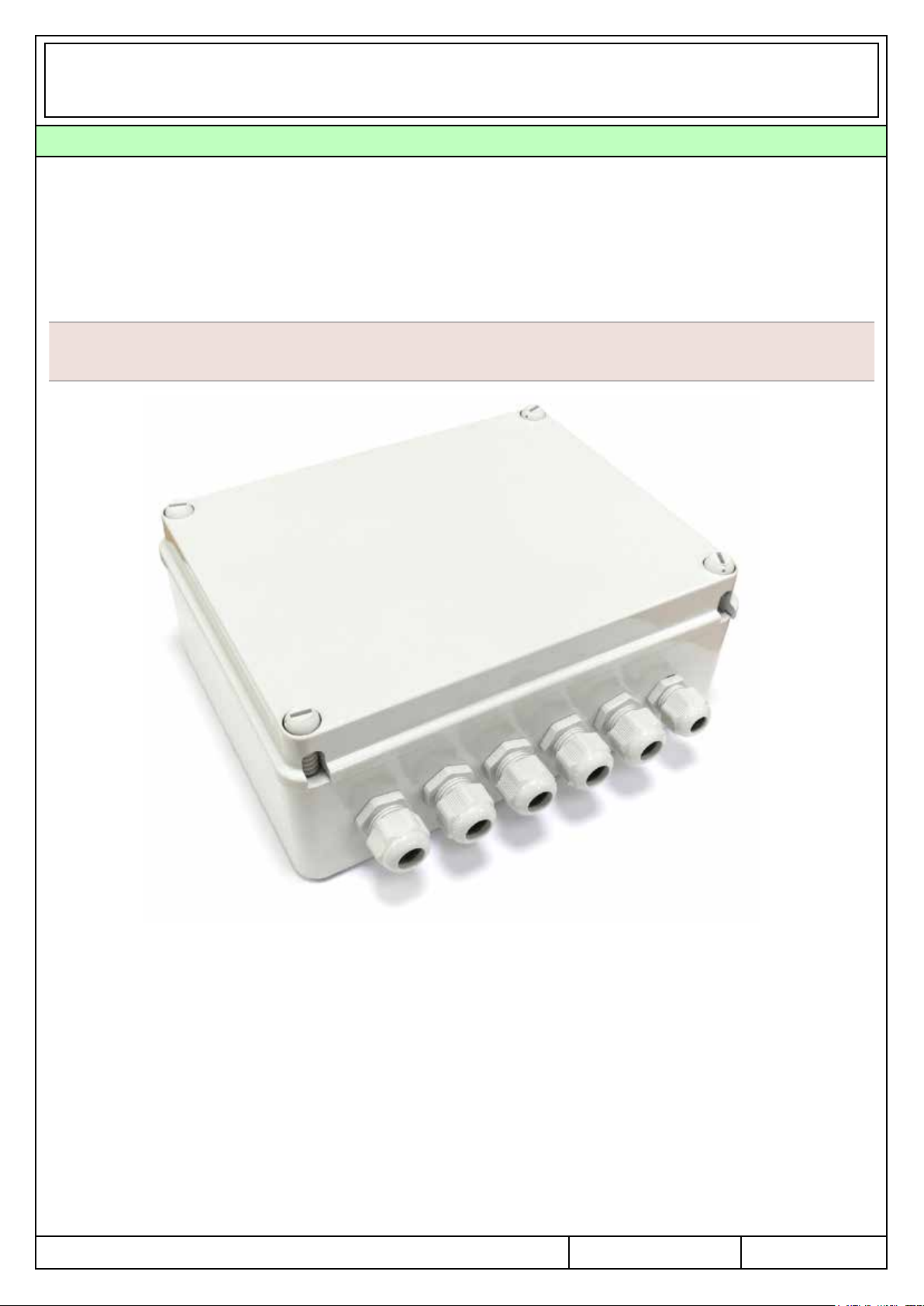
4 OUTPUT RADIO RECEIVER FOR THE CONTROL OF RLC LOAD
Universal dimmer for the radio control of resistive, inductive, capacitive loads, LED and motors for fans.
4 output with 500W maximum power each at 230Vac or 250W each at 110Vac.
Power supply Minimum power (each output) Maximum power (each output)
230Vac 50/60Hz
25W (R) - 25VA (L,C) - 7W (Led)
500W (R) - 500VA (L,C) - 100W (Led)
110Vac 50/60Hz
12W (R) - 12VA (L,C) - 4W (Led)
250W (R) - 250VA (L,C) - 50W (Led)
Characteristics
Suitable for any type of load, thanks to the manual or automatic conguration of the output
Controlled by transmitters or wired push-buttons with function ON/OFF and Dimming (0%-100%)
Controlled by wireless movement sensors
Compatible with Green Mouse, for the automatic control of the lights
1
Page 2
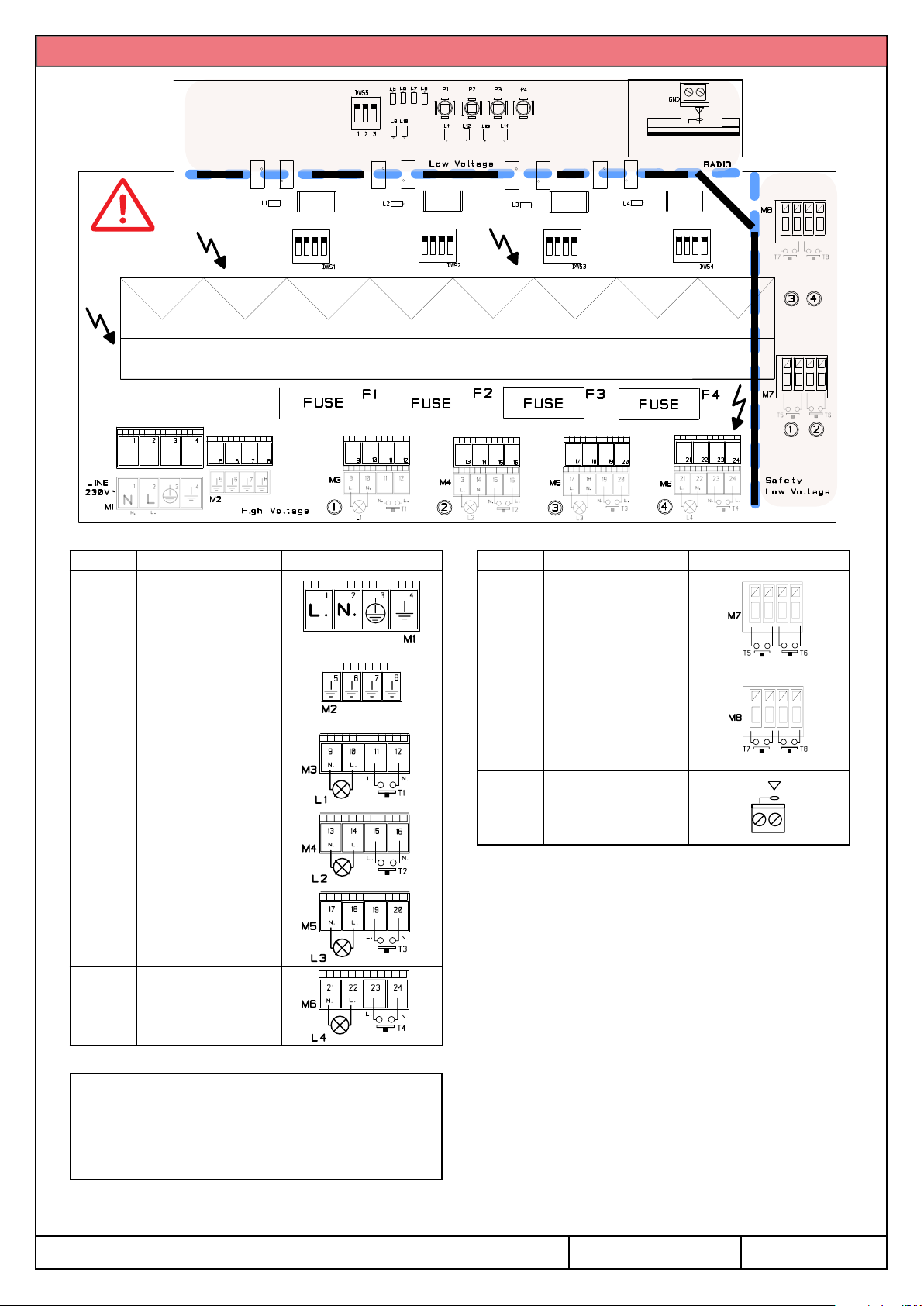
Wiring diagram
DANGER
Hi-Voltage
Safety LowVoltage Zone
Heatsink wired to ground
Terminal Contact
1: Line
M1
M2
M3
M4
M5
M6
2: Neutral
3: Main GND
4: GND
5: GND for L1
6: GND for L2
7: GND for L3
8: GND for L4
9-10: Load (L1)
11-12: wired input T1
13-14: Load (L2)
15-16: wired input T2
17-18: Load (L3)
19-20: wired input T3
21-22: Load (L4)
23-24: wired input T4
Terminal Contact
M7
M8
ANT aerial connection
wired input T5
wired input T6
wired input T7
wired input T8
The receiver has four wired safety low voltage
input and four wired high voltage input with the
same functions:
- T1, T2, T3, T4: ON/OFF and DIM the load
Short pulse (<400mS) = ON/OFF
Long pulse (>400mS) = adjusting upgrade or
downgrade if the output set in dimming mode
Attention:
High-Voltage board, risk of electric shock!
Never touch the board outside the safety zone.
The output are protected by 3.15A fuses.
If not used, close cable glands with their caps.
- T5, T6, T7, T8: ON/OFF and DIM the load
Short pulse (<400mS) = ON/OFF
Long pulse (>400mS) = adjusting upgrade or
downgrade if the output set in dimming mode
Note: it is possible to connect more push-buttons
in parallel mode to the same input.
2
Page 3
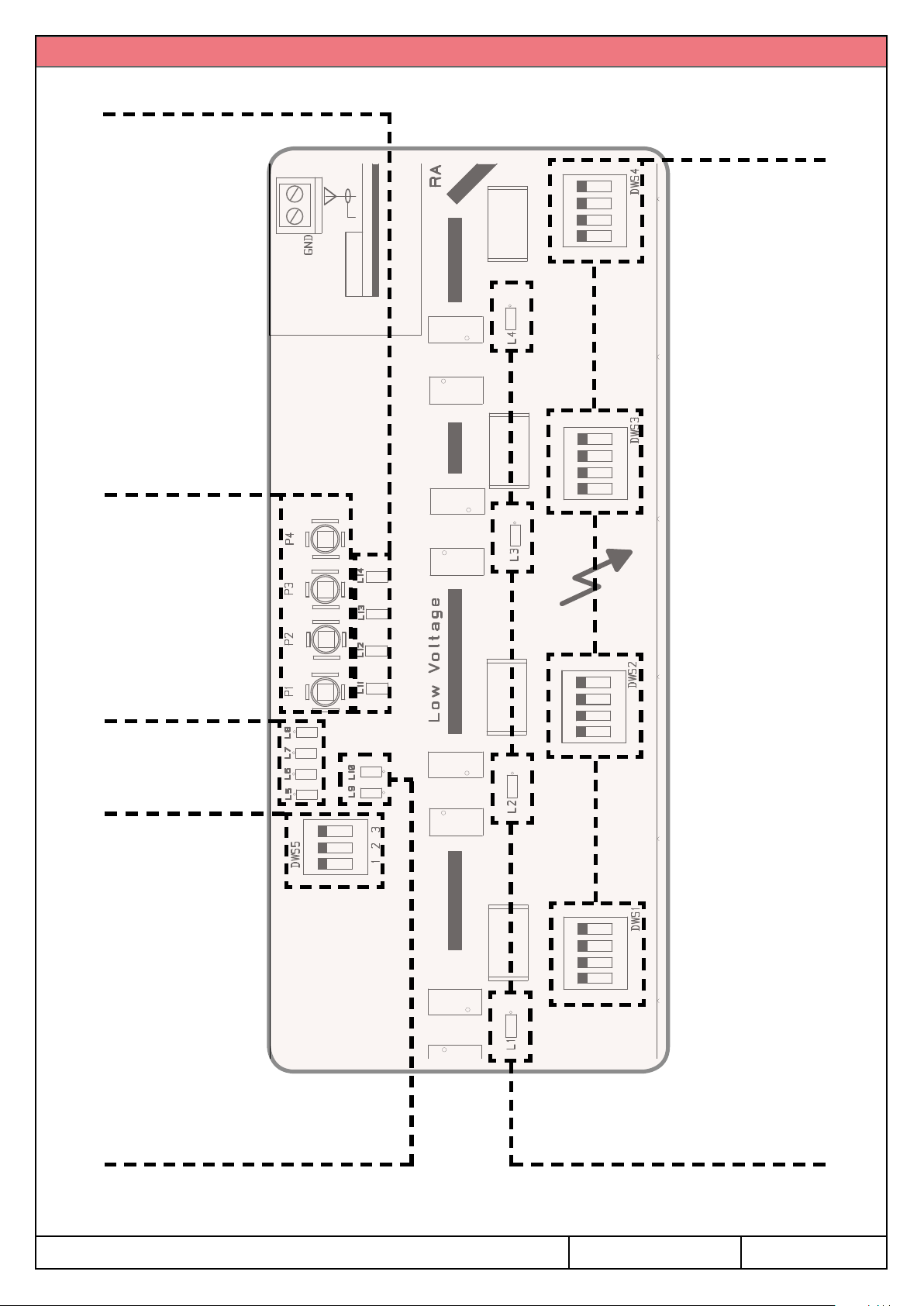
LED and DIP-Switch Diagram
Output 1, 2, 3, 4
means of wired input
SELECTED OUTPUT
P1: ON/OFF/Dim
ON = output selected by
P2: memorize TX
P3: delete TX
P4: output selection
(see p. 4)
Output 1, 2, 3, 4
LOAD SETTING DIP
SELECTED OUTPUT
Output 1, 2, 3, 4
ON = output selected by
means of P4 button or
associated to the received
radio transmission
(see p. 4)
Output 1, 2, 3, 4
PIR SETTING DIP
L9 ON = Received
radio transmission
L10 ON = Powered
LED ERROR
Output 1, 2, 3, 4
- Fix: overload
- Blinking: overtemperature
3
Page 4

DIP-Switch conguration
WARNING: Dip-switch connected to high-voltage (load setting) cannot be used if the power is ON!
Load setting dip-switch (high voltage)
Setting is NOT possible when the power is ON
1 2 3 4
ON
1 2 3 4
ON
FUNCTIONING MODE
OFF = switching mode
ON = dimming mode (default)
1 2 3 4
ON
1 2 3 4
ON
Automatic identication
of the load
Resistive load
Identication of the load
Before the rst power-ON of the control unit, set the correct
load type for each output, using the proper dip-switch.
1 2 3 4
ON
1 2 3 4
ON
Inductive load
(in this case do not use STL001)
Capacitive load
If the type of load is unknown, set the dip-switch for
the automatic identication of the load: control unit
will automatically adjust the settings, adapting to the
connected load.
If the functioning of the load is not satisfying, perform the
1 2 3 4
ON
1 2 3 4
ON
1 2 3 4
ON
AC motors for fans
(in this case do not use STL001)
LED
(default)
LED with STL001 circuit
procedure of ne-adjustment (see par. 3.3, page 13),
keeping the dip-switch conguration as it is.
In case of a later modication of the load type, it might
be necessary adjusting the minimum level (see par.
3.2, page 13), or delete and memorize the associated
trasmitters again.
PIR dip-switch (low voltage): set of the activation time of the load once activated by PIR sensor (valid
for all the output).
Setting is possible when the power is ON
1 2 3
ON
OFF
1 2 3
ON
2,5 minutes
1 2 3
ON
1 2 3
ON
1 2 3
ON
15 seconds
30 seconds
60 seconds
1 2 3
ON
1 2 3
ON
1 2 3
ON
5 minutes
10 minutes
20 minutes
4
Page 5
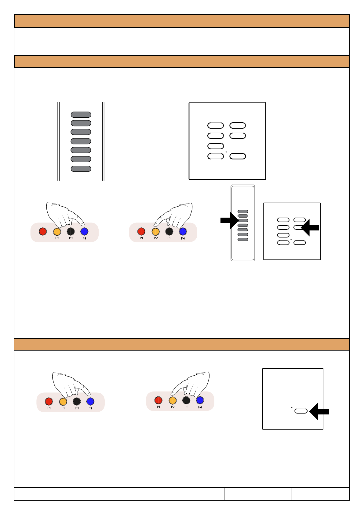
1 - Transmitters Memorization
Before memorizing the transmitters select the output associated to the transmission channel by pressing the
button P4 (blue). The selection is indicated by the relative LED on. It is possible to memorize the transmitter
to one or more outputs.
1.1 - Memorization of 7/42 channel transmitters
Short presses of the buttons CH1..CH4 command the preset scenes. CH5 and CH6 adjust the level of the
load (Dim UP and Dim DOWN). Short press of CH7 turns OFF the output. All the buttons of the transmitter
are automatically memorized.
CH1
CH2
CH3
CH4
CH5
CH6
CH7
100%
75%
50%
Min.
Dim +
Dim OFF
Press P4
to select the output
1- Select the output to associate
by pressing the button P4 (the
selection will be indicated by
the relative led ON).
100%
75%
50%
Min.
CH1
CH2
CH3
CH4
Press P2 once
and hold it down
2- Press the button P2 once
and hold it down; the buzzer
will sound a continuous beep.
CH5 Dim +
CH6 Dim -
CH7 OFF
3- During the beep sound press any button
of the 7/42 channel transmitter to memorize;
the memorization is indicated by the
intermittent sound of the buzzer.
ATTENTION: if the load conguration is changed from INDUCTIVE to any other or viceversa, the presets
relative to buttons CH1..CH4 could be different as shown here above. In this case the associated transmitters
must be deleted and memorized again.
1.2 - Memorization of one transmitter button with On/Off/Dim function
With short impulses turn the load on and off; keeping it pressed to dim UP or DOWN the load.
Press P4
to select the output
1- Select the output to
associate by pressing the
button P4 (the selection
will be indicated by the
relative led ON).
2- Press the button P2 twice and
hold it down the second one, the
buzzer will make a beep each time
and then sounds continuously.
Press P2 twice
and hold it down
3- During the beep sound press
the button of the transmitter to
memorize; the memorization
is indicated by the intermittent
sound of the buzzer.
5
Page 6

1.3 - Memorization of one transmitter button with ON function
The button memorized with On function turns on the control unit at the last output level.
Press P4
to select the output
1- Select the output to
associate by pressing the
button P4 (the selection will
be indicated by the relative
Press P2 three times
and hold it down
2- Press the button P2 three times
and hold it down the third one, the
buzzer will make a beep each time
and then sounds continuously.
led ON).
1.4 - Memorization of one transmitter button with OFF function
The button memorized with Off function turns off the load.
Press P4
to select the output
1- Select the output to
associate by pressing the
button P4 (the selection will
be indicated by the relative
led ON).
Press P2 four times
and hold it down
2- Press the button P2 four times
and hold it down the fourth one, the
buzzer will make a beep each time
and then sounds continuously.
3- During the beep sound press
the button of the transmitter to
memorize; the memorization is
indicated by the intermittent sound
of the buzzer.
3- During the beep sound press
the button of the transmitter to
memorize; the memorization is
indicated by the intermittent sound
of the buzzer.
1.5 - Memorization of 3 channel transmitters
The buttons of the memorized transmitter will have the following functions:
CH5 dim UP, CH6 dim DOWN and CH7 turns ON/OFF the load.
Press P4
to select the output
1- Select the output to
associate by pressing the
button P4 (the selection will
be indicated by the relative
led ON).
Press P2 ve times
and hold it down
2- Press the button P2 ve times and
hold it down the fth one, the buzzer
will make a beep each time and then
sounds continuously.
3- During the beep sound press the
button of the transmitter to memorize;
the memorization is indicated by the
intermittent sound of the buzzer. All
the buttons of the transmitter are
automatically memorized with a preset
conguration as in the above drawing.
CH5: Dim +
CH6: Dim CH7: On/Off
6
Page 7

1.6 - Memorization of Green Mouse (ONLY for output set as dimming mode)
Green Mouse is a wireless transmitter for the automatic control of the light in a room.
The light level is automatically adjusted as the variation of the natural light, keeping the level congured
by the user through the command buttons 2 and 3.
Note: during the normal functioning, Green Mouse is excluded from the receiver after each OFF
command given by other transmitters or from external buttons. Green Mouse will resume the automatic
adjustment of light at the next switching on of the receiver.
See the instruction manual of the product for further details.
2
3
Press P4
to select the output
1- Select the output to
associate by pressing the
button P4 (the selection
will be indicated by the
2- Press the button P2 six times
and hold it down the sixth one, the
buzzer will make a beep each time
and then sounds continuously.
Press P2 six times
and hold it down
relative led ON).
1.7 - Memorization of 4 channel transmitters
Press P4
to select the output
1- Select the output to
associate by pressing the
button P4 (the selection
will be indicated by the
relative led ON).
Press P2 seven times
and hold it down
2- Press the button P2 seven times
and hold it down the seventh one,
the buzzer will make a beep each
time and then sounds continuously.
3- During the beep sound press
button 2 or 3 of Green Mouse; the
memorization is indicated by
the intermittent sound of the buzzer.
CH1: 100%
CH2: 50%
CH3: min
CH4: Off
3- During the beep sound press the
button of the transmitter to memorize;
the memorization is indicated by the
intermittent sound of the buzzer. All
the buttons of the transmitter are
automatically memorized with a preset
conguration as in the above drawing.
1.8 - Memorization of one transmitter button with ON-OFF function
With short impulses turn the load on and off.
Press P4
to select the output
1- Select the output to
associate by pressing the
button P4 (the selection
will be indicated by the
relative led ON).
Press P2 eight times
and hold it down
2- Press the button P2 eight times
and hold it down the eighth one,
the buzzer will make a beep each
time and then sounds continuously.
3- During the beep sound press
the button of the transmitter to
memorize; the memorization
is indicated by the intermittent
sound of the buzzer.
7
Page 8

1.9 - Memorization of wireless PIR
The wireless movement sensors (PIR) can be used to automatically activate the load at 100%. In case the
timer is active (see p.4) the load automatically returns to the previous level after the set time. It’s possible
to interrupt the automatic functioning at any time just using any memorized transmitter. Once pressed any
button of a memorized transmitter, the PIR will be disabled for 60 seconds.
Press P4
to select the output
1- Select the output to
associate by pressing the
button P4 (the selection
will be indicated by the
relative led ON).
Press P2 nine times
and hold it down
2- Press the button P2 nine
times and hold it down the
ninth one, the buzzer will
make a beep each time and
then sounds continuously.
3- During the beep
sound activate the
sensor; the memorization
is indicated by the
intermittent sound of the
buzzer.
Teleco TVTXSxx
Teleco TVTXLR02x
Other applications with PIR
• TRANSMITTER WITH TIMER: If a transmitter is memorized with this procedure, it will work as a PIR,
activating the dimmer for the time set with the PIR dip switch (page 3).
• PIR WITH BOTH ON & OFF COMMAND: The movement sensor (PIR) Teleco TVTXSxx and the
transmitter Teleco TVTXLR02x for standard movement sensors, transmit on 2 radio channels, which
can be assigned to separate commands ON and OFF using the procedure at paragraph 1.3 and 1.4.
In this application the dip switch for PIR settings will have no effect.
• PIR COMMANDING TWO PRESETS: the 2 channels of TVTXSxx and TVTXLR02x can be assigned
to the preset values of activation (100% = recognized movement; 66% = NO movement) which are
CH1 and CH2 of a 7 channel transmitter (see the procedure 1.1). In case the levels of the 7 channel
transmitter used for the procedure have been modied, they will be copied in PIR instead of default
preset values (see procedures 1.11 and 1.13).
1.10 - Disabling/enabling a single button of a 4 or 7/42 channel transmitter
Press P4
to select the output
1- Select the output to
associate by pressing the
button P4 (the selection will
be indicated by the relative
led ON).
Press P2 ten times
and hold it down
2- Press the button P2 ten times
and hold it down the tenth one, the
buzzer will make a beep each time
and then sounds continuously.
3 - During the beep sound press a button
of the 4 or 7/42 channel transmitter which
has to be disabled/enabled.
- 3 slow beeps: the button is disabled.
- Fast beeps: the button is enabled.
8
Page 9

1.11 - Changing the preset scenes of a transmitter associated to a single output
7/42 channel transmitter
Adjust
Press
CH1
CH5
CH2
CH3
CH4
1- Press the button relative to
the scene to modify.
4 channel transmitter
Press
CH1
CH2
CH3
CH4
CH6
2- Adjust the new value with
the buttons CH5 and CH6.
Adjust
CH1
CH2
CH3
CH4
Keep pressed to DIM
CH7
5 sec. press
3- Hold down CH7 button for
5 sec. At the end the load will
turn on at the new value.
CH1
CH2
5 sec. press
CH3
CH4
1- Press the button relative to
the scene to modify.
2- Adjust the new value
keeping pressed the same
button to modify.
3- Hold down CH4 button for
5 sec. At the end the load will
turn on at the new value.
1.12 - Changing the preset scenes of a transmitter associated to more than one output
In case a 4/7/42 channel transmitter is associated to more than one output, and each of them must have
different values of intensity when a preset scene is commanded, it is necessary to clearly identify the output
which relative preset will be modied.
This is possible in different ways, according to the characteristics of each installation:
a. The transmitter is associated to more than one output. No other input available.
b. The transmitter is associated to more than one output and there are also wired safety low voltage
input (T5 .. T8) to command the output.
c. The transmitter is associated to more than one output as MASTER device and there are also
transmitters associated to the single output.
9
Page 10

a. The 4/7/42 channel transmitter is associated to more than one output. No other input available.
Press
CH1
CH2
CH3
CH4
Press P4
to select the output
1- Press the button relative to the scene to modify.
All the output associated to this transmitter will
turn the load on at the preset value.
Keep pressed
to DIM
OR
CH1
CH2
CH3
CH4
CH5
CH6
7/42 CH.4 CH.
Adjust
Adjust
3- Adjust the new value:
• keeping P1 pressed to Dim UP/DOWN
• (4ch. transmitters) keeping the button relative to the
scene to modify pressed to Dim UP/DOWN
• (7/42ch. transmitters) use the buttons CH5, CH6 to
Dim UP/DOWN
Only the selected output will change its intensity.
2- Press P4 to select the output to modify
(the selection will be indicated by the
relative led ON). ATTENTION: the next
steps must to be executed within 60
seconds!
CH1
CH2
CH3
CH4
CH7
7/42 CH.4 CH.
5 sec. press5 sec. press
4- Hold down CH4 or CH7 button for 5
sec. At the end only the load connected
to the selected output will turn on at the
new value.
b. The 4/7/42 channel transmitter is associated to more than one output and there are also wired
safety low voltage input (T5 .. T8) to command the output.
Press
CH1
CH2
CH3
CH4
Keep pressed
to DIM
T5 T6 T7 T8
CH1
CH2
CH3
CH4
CH7
7/42 CH.4 CH.
5 sec. press5 sec. press
1- Press the button relative
to the scene to modify. All
the output associated to this
transmitter will turn the load
on at the preset value.
2- Adjust the new value with the wired
button connected to the output to modify
(T5 = OUT1, T6 = OUT2, T7 = OUT3,
T8 = OUT4).
3- Hold down CH4 or CH7
button for 5 sec. At the end
only the load connected to the
selected output will turn on at
the new value.
Note: It’s not possible to use the high voltage input for this procedure.
10
Page 11

c. The 4/7/42 channel transmitter is associated to more than one output as MASTER device and
there are also transmitters associated to the single output.
OUT1OUT2OUT3OUT
4
1 2 3 4
SINGLE OUTPUT
MASTER
(4/7/42 channels)
Press
CH1
CH2
CH3
CH4
1- Press the button relative
to the scene to modify. All
the output associated to this
transmitter will turn the load
on at the preset value.
Single output tx
(1 or 2 or 3 or 4)
2- Adjust the new value with the
transmitter associated ONLY to the
desired output. Use the button with
function Dim + and Dim -, or turn
the output ON/OFF.
TRANSMITTER
(any type)
CH1
CH2
CH3
CH4
3- Hold down CH4 or CH7
button for 5 sec. At the end
only the load connected to the
selected output will turn on at
the new value.
CH7
7/42 CH.4 CH.
5 sec. press5 sec. press
1.13 - Copying the function of a transmitter to a new transmitter
The button P3 is located inside the transmitter (see transmitter manual).
The new transmitter will have the same functions of the transmitter used for its memorization.
Press
Press
Press
3- During the sound press the
button of the new transmitter
which has to be memorised; the
memorization is indicated by the
intermittent sound of the buzzer.
1- Press the button P3.
The enabled receiver
sounds continuously.
P3
2- Within 5 sec. press a button of the
already memorized transmitter of
which the function has to be copied.
The buzzer will interrupt the sound for
1 sec., and then carry on for 5 sec.
Attention: when a 4 or 7/42 channel transmitter is copied, also its preset levels will be copied
into the new one.
Function available
for all type of
transmitters
11
Page 12

2.1 - To delete a transmitter
Press
Press P4
to select the output
1- Select the output to associate
by pressing the button P4 (the
selection will be indicated by the
Press P3 once
and hold it down
2- Press the button P3 once
and hold it down, the buzzer will
sound slowly and intermittently.
relative led ON).
2.2 - To delete all transmitter from the selected output
1- Select the output using P4
2- Press the button P3 two times and hold it down for
10 sec., the buzzer will make one beep and then sound
quickly and intermittently.
3- At the end the buzzer will sound continuously by
Press P4
to select the output
Press P3 twice
and hold it down for 10 sec.
indicating that all the transmitters associated to the
output have been deleted.
2.2 - To delete all transmitter from the memory
1- Clean the output selection using P4. Output LED
must be all OFF.
2- Press the button P3 two times and hold it down for
10 sec., the buzzer will make one beep and then sound
quickly and intermittently.
3- At the end the buzzer will sound continuously by
Press P4
to de-select the output
Press P3 twice
and hold it down for 10 sec.
indicating that the whole memory has been deleted.
3- During the sound press the button
to delete; the deletion is indicated by
the continuous sound of the buzzer.
2.4 - To delete a transmitter from transmitter
2- During the intermittent
sound press the button
which is to be deleted;
the deletion is indicated
by the continuously
sound of the buzzer.
Press
P3
1- Press three
times the button
P3 placed inside of
the transmitter. The
buzzer will sound
intermittently and
slowly.
Press
2.5 - Errors during the memorization or deletion
If the code hasn’t been memorized it could be due to the following reasons: the code already exists in
memory or the memory is full. If the code hasn’t been cancelled the code doesn’t exist in memory.
Memory full or empty: the buzzer will sound intermittently and slowly for 3 seconds each time it is switched
on or during the memorization phase.
12
Page 13

3.1 - Activation/Deactivation of the Memory of the last value of the Load
Activated: commanding the load with a short pulse, it will turn-on with the same values it had before the last
OFF command.
Deactivated: commanding the load with a short pulse, it will turn-on always at 100%.
1- Select the output using P4
2- Press P1 + P3 and hold them down.
- Fast beeps: the function is activated.
Press P4
to select the output
Press P1+P3 once
and hold them down
- 3 slow beeps: the function is deactivated.
NOTE: after a power failure, the dimmer will turn on the loads at the same status before it.
3.2 - To set the minimum level for the Load
This function allows to set the minimum level for dimming the load, only in case of resistive loads
(DIP2 = ON).
1- Adjust the minimum desired level of the load.
2- Press P2 + P3 and hold them down.
The buzzer makes fast beeps.
To reset the level to the default value, press
Press P4
to select the output
Press P2+P3 once
and hold them down
again P2 + P3 and hold them down.
The buzzer makes 3 slow beeps.
3.3 - Fine adjustment for load identication (see load setting at page 3)
This function modies the settings of the control unit in the automatic identication of the load type.
It’s allowed only if the dip-switch 2, 3 and 4 are OFF (conguration corresponding to automatic
identication).
1 2 3 4
ON
1 2 3 4
ON
Press P4
to select the output
1- Select the output using P4
2- Press P1 + P2 + P3 and hold them down.
- Fast beeps: the function is activated.
- 3 slow beeps: the function is deactivated.
Press P1+P2+P3 once
and hold them down
13
Page 14

Warnings
IMPORTANT! READ THIS INSTRUCTIONS CAREFULLY BEFORE INSTALLING AND
COMMISSIONING THE PRODUCT. SAVE THESE INSTRUCTIONS FOR FUTURE REFERENCE.
PRODUCT INSTALLATION
The product at issue must be installed, commissioned and maintained only by licensed and authorised people, respecting
the laws concerning the electrical installations. Not conforming installations, wrong adjustments or product alterations may
cause re, electric shock, or personal injuries. The manufacturer is not responsible for any damage due to wrong installation
or improper use. Attention: at the power-on the device resumes the status it had before the turning-off.
MOUNTING LOCATION AND MODALITY
The product must be mounted applying the following indications carefully:
• it must be xed on surfaces which cannot be damaged by the high temperature.
• it must be placed in a well ventilated location. It cannot be hermetically closed.
• it must be xed vertically, with cable glands downward.
• connection cables must be protected against any accidental impacts, using proper pipes.
• do not cover the product.
• do not use or store ammable materials close to the product.
ELECTRICAL CONNECTIONS
All the connections must be rated for a single-phase 110/230Vac power supply, with the relative Earth connection. For the
disconnection from the power line, use an all-pole switch with contacts having a dimension of at least 3,5mm. Arrange all
the necessary safety devices and use only materials complying with the standard of electrical installations. Signal and
power voltage wiring (110/230Vac) must be separated one from the other. The cable must have a section properly rated
according to the load connected and a nominal temperature range (T) up to 90°C. The following table reports (roughly) the
resistance values and the maximum current of a copper wire, according to its length:
Section (mm2) R (ohm/Km) Max. current (A)
1 19.5 5
1.5 13.3 10
2.5 7.98 16
WARNING: If any cable is damaged, it must be immediately replaced by a qualied person in order to avoid any hazard.
SAFETY INFORMATION
This appliance is not intended for use by people (including children) with reduced physical, sensory or mental
capabilities, or not properly informed about the product’s characteristics or the possible hazards it can cause.
Children should be carefully supervised when they are in the area of the product. Do not touch the electronic board
with wet hands, any metallic or ammable objects. Do not operate in the high voltage area of the electronic board,
when it is supplied. Do not touch the heatsink, for at least 15 minutes after the switching off of the product. Use the
product only in combination with devices which can guarantee a safe extended time functioning. The radio signal
reception of the device could be disturbed by the presence of electrical disturbances being transmitted by
other appliances working on the same frequency or if the product is somehow shielded by metal parts.
PRODUCT DISPOSAL
At the end of this product’s useful life, it must not be disposed of as domestic waste, but must be taken to a collection
centre for waste electrical and electronic equipment. It is the user’s responsibility to dispose of this appliance through the
appropriate channels at the end of its useful life.
Hereby Teleco automation s.r.l. declares that the product complies with the essential requirements and other relevant
provisions, established by the Directive 1999/5/EC. The declaration of conformity can be consulted on the web site:
www.telecoautomation.com/ce. In the view of a constant development of their products, the manufacturer reserves the
right for changing technical data and features without prior notice.
14
Page 15

TECHNICAL SPECIFICATIONS
- Power supply 110/230Vac 50/60Hz
- Max Output Power 2000W (500W for each output) at 230Vac~
1000W (250W for each output) at 110Vac~
- Reception frequency 868.3 MHz (TVDMM868A05)
916 MHz (TVDMM916A05)
- Operating temperature range -20° / +45°C
-The maximum number of memorizations is 64.
98 mm
28 mm
200 mm
254 mm
194 mm
140 mm
15
Page 16

 Loading...