

Page 1
TELECO AUTOMATION SRL
TELEPHONE: ++39.(0)438.388511 FAX: ++39.(0)438.388536
(teleco.automation@nline.it www.telecoautomation.com)
This document is the property of Teleco Automation SRL who reserve all reproduction and copying rights
DIGITAL RADIO CONTROL SYSTEM RCL433A03
This product must only be installed by technically qualified personnel in
conformity with the local standards and regulations in force.
All wiring and connections must be prepared for a 230V single phase
power supply. The materials used must guarantee suitable isolation
according to the local electrical standards and regulations in force. The
programmer only carries out remote commands via radio and all safety
devices required by the system must be prepared apart.
The device’s signal reception could be disturbed by several factors
such as:
- the presence of electrical frequency noise being transmitted by other
appliances working in the same environment and on the same frequency .
- appliances installed in containers with metal parts; only use containers
made of plastic.
- the aerial wire cabled together with power cables; position the aerial
wire as far away as possible from power cables.
Product description
Radio control devices in the UHF band with superheterodyne receivers
and transmitters using a saw resonator controlled carrier frequency
for ON/OFF type, impulsive or bistable commands.
The rolling code signal transmission makes duplication impossible.
The first code inserted for each channel must be inserted directly using
the button located inside the receiver while successive transmitters
can be inserted via radio using a transmitter that is already present in
the receiver’s memory. This allows you to insert new transmitters into
an existing system without having to open the receiver. This operation
can be carried out by the end user without having to call an installer but
still guaranteeing the secrecy of the code.
The code is memorised in the receiver in an EEprom module that maintains
the information even in case of blackouts. This module can be
transferred into another receiver in case of failure without compromising
the integrity of the memorised codes.
The receiver is supplied in a waterproof container IP54. The channel
outputs have 16A contacts and the voltage is 230V . Each channel
can accept a resistive load of up to 1000VA .
Transmitter versions TXP....TXW....
The transmitters are pre-coded by the manufacturer and each has its
own unique code.
Transmitters
TXR433A01 1-channel transmitter
TXR433A02 2-channel transmitter
TXR433A04 4-channel transmitter
Mini-transmitters
TXP433A01 Mini 1-channel transmitter
TXP433A02 Mini 2-channel transmitter
TXP433A04 Mini 4-channel transmitter
Wall mounted versions
TXW433A02 2-channel transmitter
TXW433A04 4-channel transmitter
SW1 functions (the “ON” position is indicated by the arrow on
the dip-switch).
In the “ON” position the channels are impulsive. In the “ OFF” position
the channels are bistable “ON/OFF”
Dip 1 : function selection Ch1 (relay 1)
Dip 2 : function selection Ch2 (relay 2)
Dip 3 : function selection Ch3 (relay 3)
Memorising remote controls
For security reasons cancel the entire memory content before each
installation
Each channel is associated with a button:
M1 with relay 1, M2 with relay 2, M3 with relay 3.
1)Press and hold down the button corresponding to the relay that you
want to associate with the channel on the transmitter that is to be
memorised. The buzzer B1 will emit a constant sound.
2)Transmit the channel to be memorised. The buzzer B1 will emit an
intermittent sound.
To insert a new code repeat operations 1 and 2.
If the code hasn’t been memorised it could be due to the following reasons:
- The code already exists in memory
- The memory is full (maximum of 32 different codes ), in this case the
buzzer will sound at 3-second intervals each time you switch on.
To cancel a code :
1) Press and hold down one of the buttons M1-M2-M3. The buzzer B1
will sound slowly.
2)Transmit the code to be cancelled and once cancelled the buzzer B1
will sound constantly.
To cancel a code repeat operations 1 and 2.
To cancel all codes in memory :
1)Press and hold down the buttons M1 and M4 simultaneously . The buzzer
B1 will emit a rapid intermittent sound, keep the buttons held down until
the buzzer B1 emits a constant sound. After completion release the
buttons.
How to insert a transmitter via radio, using an already memorised
transmitter and without accessing the receiver (memorisation
procedure using indexing)
1) Press the internal button P3 in an already memorised transmitter, the
enabled receiver will emit a continuous sound for 5 seconds.
2) Transmit a channel that is present in the memory of the receiver that
has to memorise the new code within 5 seconds. The buzzer will stop
sounding for 1 second and then sound again for another 5 seconds.
(this operation is required to index the new code in the empty receiver).
3) Transmit the new code to be memorised within 5 seconds. Successful
memorisation is indicated by the buzzer emitting an intermittent sound.
To insert other functions repeat operations 1-2-3.
If the receiver’s memory is full the buzzer B1 will sound intermittently
indicating that the receiver cannot be enabled.
If the code hasn’t been memorised it could be due to the following reasons:
- the code already exists in memory
- the memory is full and in this case the buzzer will sound at 3-second
intervals each time you switch on.
Aerials
T o obtain the best performance the installation of an aerial is fundament al.
Connect a 17 cm wire to the middle binding post on the aerial.
For better results connect a tuned aerial to the receiver using coaxial
cable RG58 (impedance 50 Ω) with a maximum length of 15 metres (mod.
ANT433).
TRANSMITTERS
-carrier frequency 433.92 MHz
-carrier frequency tolerance ±75 KHz
-band width >25 KHz
-apparent radiated power -10÷-7dBm (100-200µW)
- apparent power of the harmonic products <-54 dBm (<4nW)
-modulation AM/ASK
-modulated signal PCM, 1.3 ms/bit
-power supply For TXW433 12V ± 10%
(alkaline battery GP23A)
-power supply For TXP433 3V ± 10% (lithium battery CR2032)
-operating temperature range - 10° - +55°C
RCL433A03
RS433
DateCode Number: Series Model number Draft
T214.01 21-11-03
Page 2
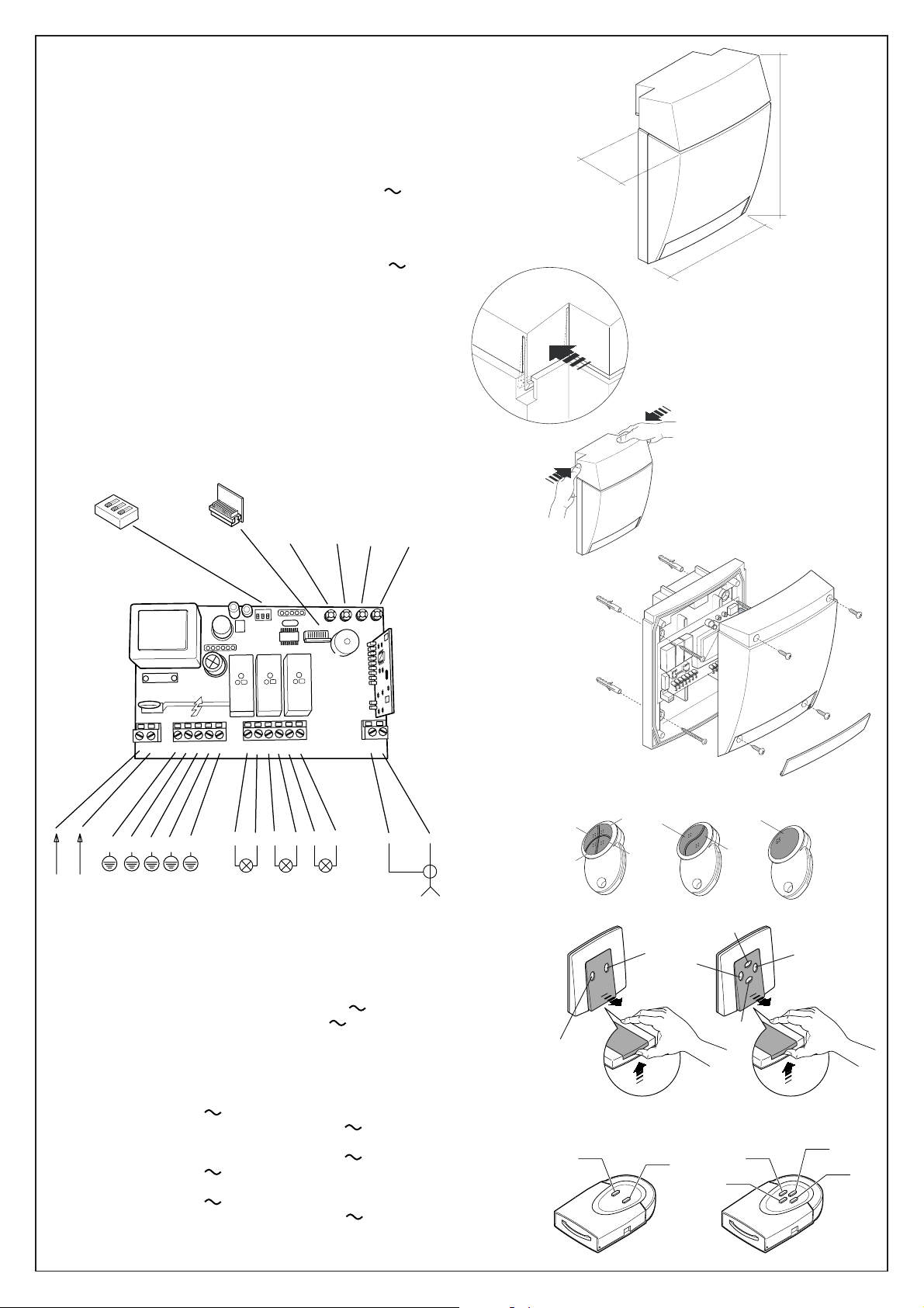
RECEIVER
C2
C3
C1
C4
C2
C1
-reception frequency 433.92 MHz
-local oscillation frequency 433.42 MHz
-local oscillation frequency tolerance ±75 KHz
-local oscillation frequency emission <57dBm
-intermediate frequency IF 500 KHz
-aerial input impedance 50 Ω
-sensitivity (finely tuned signal) 1 µV
-power supply 230V
-maximum power consumption at rest 14 mA
-maximum power consumption at rest with 1 activated relay 40 mA
205 mm
85 mm
maximum commutable power at the relay with resistive load:
-maximum voltage 230 V
-current at the relay with cos-ph 1 16 A
-channel activation delay 150 ms
-channel disactivation delay 300 ms
-operating temperature range -20° - + 55°C
DS W1
1
2
3
Memory Module
M1
M2 M3 M4
RF MODULE
CH1
CH2
CH3
145 mm
89
LP1
N.
N.
10 11 12 13
N.
LP2 LP3
16
1
2 3 4567
N.
F.
Connection binding posts:
Binding post nr.1 Neutral power supply 230V
Binding post nr.2 Live power supply 230V
Binding post nr.3 Unit earth connection
Binding post nr.4 Earth connection light LP1
Binding post nr.5 Earth connection light LP2
Binding post nr.6 Earth connection light LP3
Binding post nr.8 230V output light LP1
Binding post nr.9 Neutral power supply 230V light LP1
Binding post nr.10 Neutral power supply 230V light LP2
Binding post nr.11 230V output light LP2
Binding post nr.12 230V output light LP3
Binding post nr.13 Neutral power supply 230V light LP3
Binding post nr.16 Aerial mass
Binding post nr.17 Aerial pole
TXP433A01-02-04
17
TXW433A02-04
TXR433A01-02-04
C3
C1
C2
C2
C1
C4
C1
C2
C1
C2
C1
C4
C3
 Loading...