

Teleco Motostat digimatic 65, Motostat digimatic 85 Installation Manual And User's Manual

UK
INSTALLATION GUIDE
AND USER MANUAL

Information
Congratulations on your purchase! MotoSat is among the most technologically advanced
products in the field of satellite TV reception. This handbook has been prepared to provide
information on how to install, use, maintain and technical specifications your MotoSat.
For additional information, please contact your local dealer or directly the manufacturers:
TELECO s.p.a.
Via E. Majorana 49
48022 LUGO (RA)
Web site: www.telecogroup.com
Technical attendance: 899.899.856
TELECO .p.a. declines all responsibility for any errors contained in this manual. All the
contained information are up to the dates of printing and of the above-mentioned software
revisions. TELECO .p.a. reserves the right to introduce any modification made necessary by
the development of its products.
TELECO WARRANTY
Teleco guarantees its satellite dishes and terrestrial antennas against any
material and/or construction fault and defect. The warranty offered by
TELECO is limited to the free-of-charge replacement or repairing of any
parts that are deemed faulty by TELECO. The warranty is applicable for a
period of 3 YEARS starting from the product purchase date; however, it will
only be considered valid if the Customer is able to produce a written document
(invoice or tax receipt) showing the purchase date.
The following is excluded from the TELECO warranty:
a. Damages caused by incorrect installation and/or use and/or maintenance
b. Damages resulting from product alterations not authorised by Teleco
c. Damages resulting from the use of spare parts different from original
Teleco parts
d. Damages resulting from repairs carried out by personnel not
authorised by Teleco
e. Normal part wear;
f. Expenses incurred for spare parts transport between the Customer's
and the service centre
g. Damages that may occur during transport:
the Customer shall always be responsible for transport risks.
1

…and then drill the outside wall.
Set the drilling jig in place. Drill in the
middle of the jig (page 22)
Using a dia. 42 cutter, drill the inside
wall first…
Caution:
Mount the antenna away from the vehicle
roof edge to avoid overhanding the roof
line when travelling.
The MotoSat antenna must be installed
near a vertical wall where the wall outlet
can be fitted
Installation instructions
2
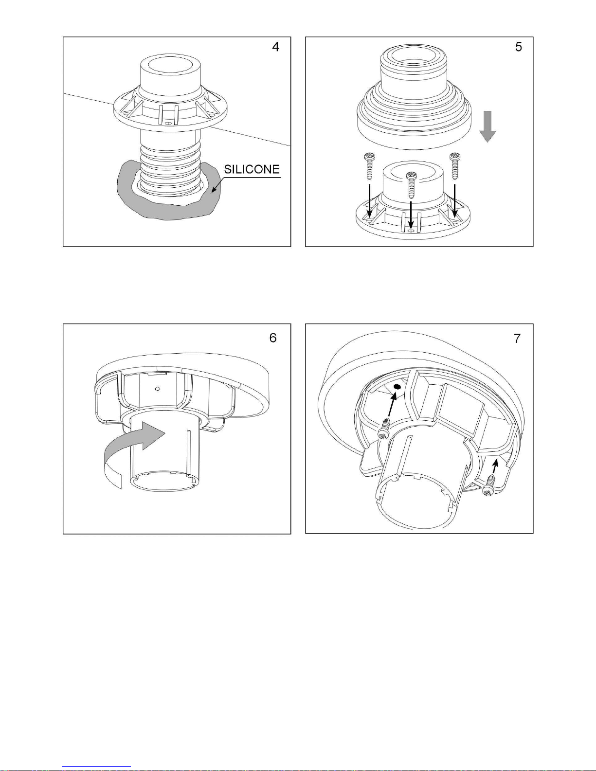
Insert the mast roof mounting bracket in
the dia. 42 hole bored in the roof, making
sure you apply a layer of silicone under
the ring nut.
Fasten the ring nut using self-tapping
screws. Place the rubber gasket over the
ring nut. ( Screws not supplied )
Secure the pipe lead to the roof using
the ring nut and its wedge-shaped spacer .
Caution: the antenna must be in horizontal
position. The wedge-shaped spacer is
used to set the antenna in the horizontal
position even if the roof is inclined.
Lock the collar on the wedge spacer
by applying the 2 screws (not supplied).
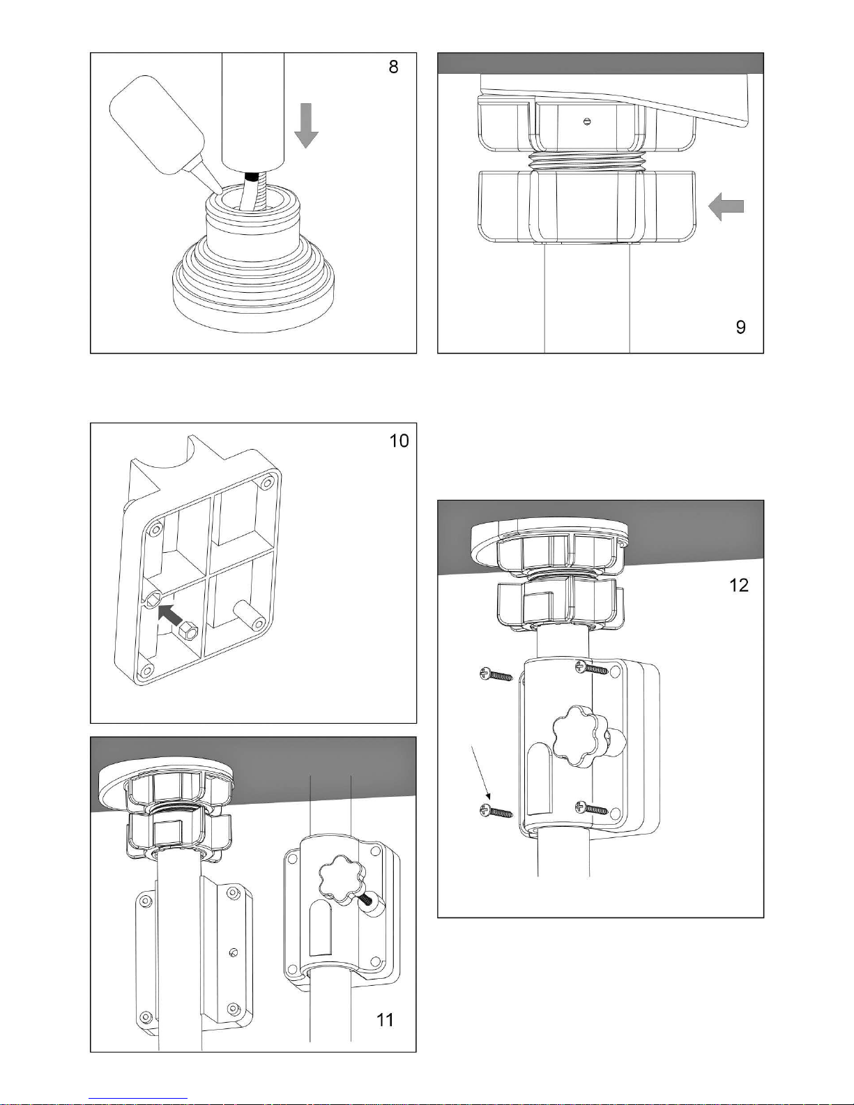
3
3,5 x 32
Introduce the
nut in its seat
on the back of
the wall outlet
Tight the locking ring nut
This mast locking device must be
screwed tight every time you wish to
secure the antenna in the desired position.
To turn or lift the mast, loosen this ring
nut.
Spread a thin film of Vaseline inside the
seal and introduce the mast
Fit the upper part of the wall outlet without
tightening all the way
Fix the outlet unit to the wall
4

Cut the antenna cable to the proper length and
apply the connector as shown on Figure. Make
sure no wire of the braiding touches the core of
the cable
Introduce the coaxial cable in the special
slot (A) and lead it out of rear bottom side
of Motosat (B)
Engage Motosat in the antenna support
tube until the tube holes are aligned with
the Motosat holes.
Fix Motosat to the antenna support tube
with the special screws.
Connect the cables as
shown in figure
Verify that the
coaxial cable
does not
obstruct the
screw hole.
Green
WhiteBrown
Coax
Receiver Sat
5

Press the UP button until a sequence of
beep sounds is obtained.
The antenna becomes automatically
positioned to facilitate installation (the
display reading is 37°).
Press the DOWN button until the
display reads OF.
Press the
DOWN button
until the display
reads OF.
Fasten the
antenna to the
arm as shown
in the figure.
6
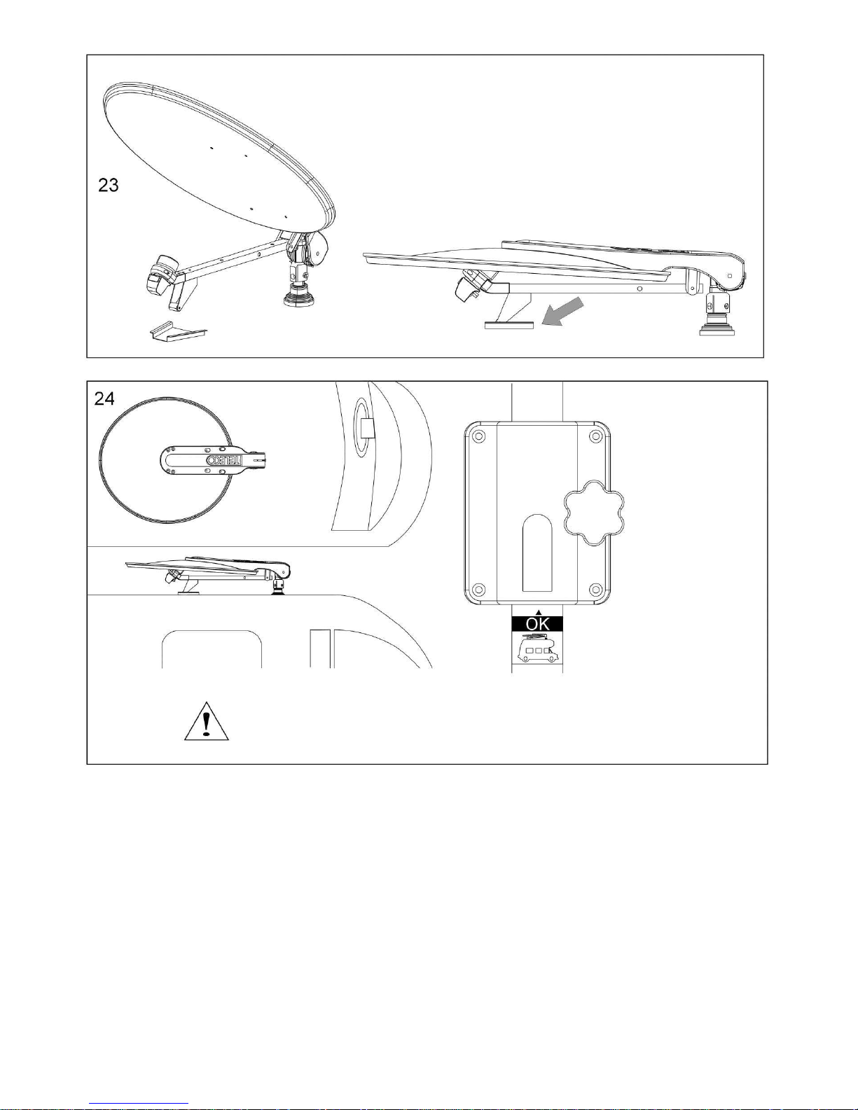
Check that the antenna has been
lowered to the required travelling
position (fig.24) and glue the steel
plate below the LNB shim to the
roof with jointing compound or
double-sided adhesive tape.
Make sure that
the antenna is
exactly in its
stowed
position. Place
the sticker on
the mast in
such a way
that you can
quickly lock the
antenna in the
right position
before every
start.
The antenna must be absolutely installed according to fig. 24, i.e.,
the disc must be bent to the rear of the vehicle.
7
 Loading...