

Page 1
V007
INSTALLATION GUIDE
and user manual
GB
Page 2

V006
Pag. 2
INDEX
TECHNICAL FEATURES ...................................................................................3
INSTALLATION TIPS.........................................................................................3
IMPORTANT NOTICE........................................................................................4
ASSEMBLY INSTRUCTIONS............................................................................. 5
USER MANUAL: Magic Sat 2002A Operation System.....................................13
Satellite seeking............................................................................................13
Antenna lowering .......................................................................................... 13
Programme seeking......................................................................................13
IMPORTANT INFORMATION for proper antenna pointing...........................14
AUTOMATIC SATELLITE SEARCHING.......................................................14
LOWERING THE ANTENNA ........................................................................ 15
ADDITIONAL OPERATIONS........................................................................ 16
Changing satellites during search ................................................................. 17
Sequential satellite seeking...........................................................................17
SAFETY FUNCTION.....................................................................................18
TROUBLE-SHOOTING................................................................................. 18
USER'S MANUAL: For the Analogue Receiver integral with the control unit....19
Control Unit Rear Panel ................................................................................19
REMOTE CONTROL MAGIC SAT 2002A ....................................................20
ON SCREEN DISPLAY.................................................................................22
SUBFUNCTIONS..........................................................................................23
CONNECTING WITH DIGITALI RECEIVER ....................................................30
Connecting with FALCON 12........................................................................ 30
Connecting with Mikro CI ..............................................................................31
Connecting with Mikro FTA........................................................................... 32
SPECIFICATIONS............................................................................................33
ESPLOSO RICAMBI..................................Errore. Il segnalibro non è definito.
RECYCLING: with a view to reducing disposal of waste
electrical and electronic equipment as much as possible,
do not throw out this end of life cycle appliance together
with other unsorted municipal waste, but make use of a
recycling centre.
Page 3
V006
Pag. 3
TECHNICAL FEATURES
1) Working voltage: 12 VDC ± 15%
2) Consumption SEARCH operation: less than 5 A RECEPTION with Dish not moving: 240
mA approx.
3) Automatic Searching Time: min 20 sec - max 5 min, depending on the place you are at
and the battery status (if the battery is not fully charged, searching takes longer)
INSTALLATION TIPS
1) The MIR remote control Extension must be installed in such a way as to make sure that
it is always visible and that the remote control can therefore operate normally.
2) Do not install the Control Unit in an area subject to liquid spilling which could cause
irreparable damage to it.
3) Do no install the Control Unit in too small a space with poor ventilation, because
excessive heat could alter its good operation.
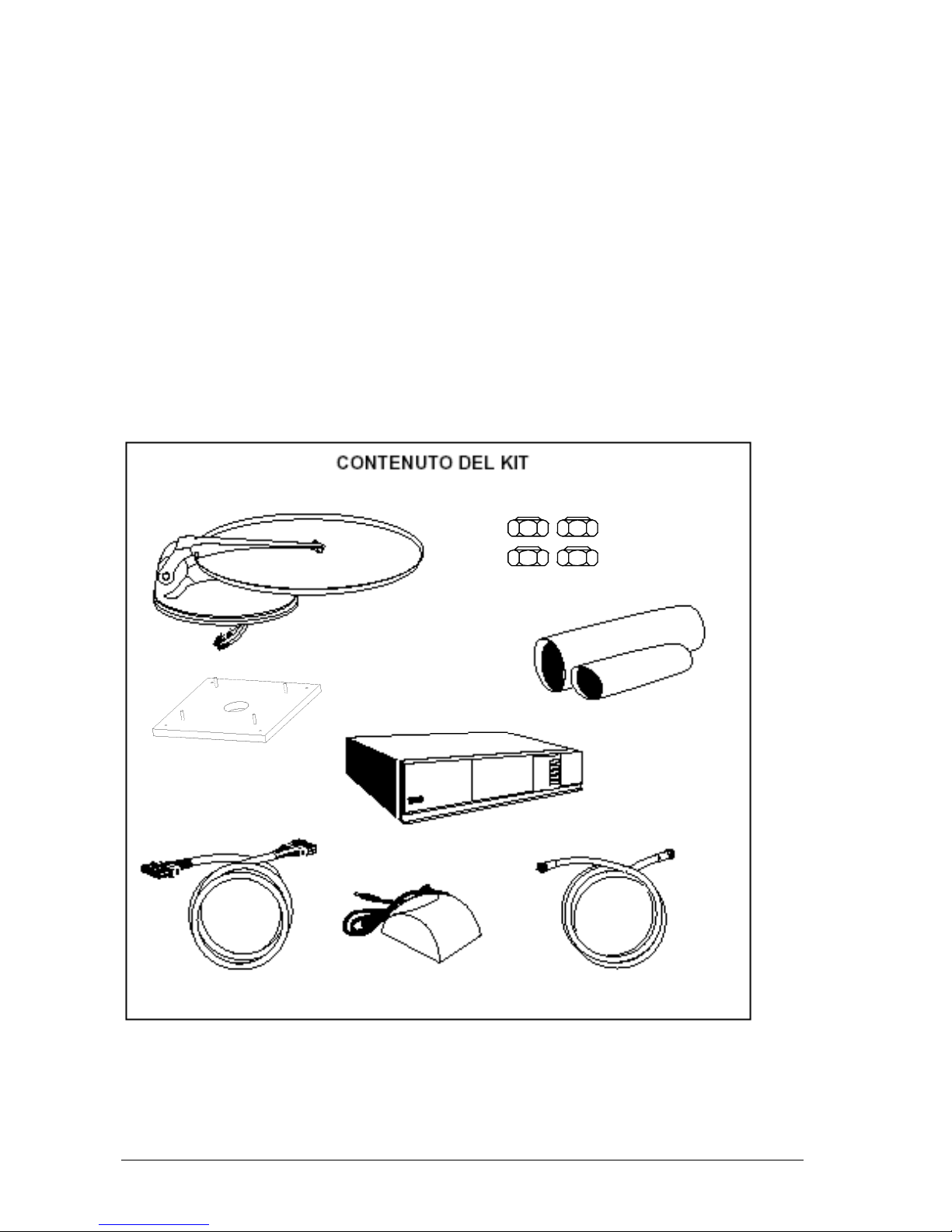
Nr. 4 Self locking
nuts Inox M6
Base plate
Outside unit
Heat-shringking tube
Control unit
Motor – Control Unit
connection cable
Remote Control Extension
Antenna – Control Unit
connection cable
Page 4

V006
Pag. 4
IMPORTANT NOTICE
1) Due to transport reasons, Magic Sat 2002A comes packaged in two separate cartons
a) The first item contains the driving unit with all the cables and the control unit.
b) the second item only contains the dish.
It is essential to check that the dish has not been damaged during transport when the
package is opened. In particular, check the following well:
• By resting the dish edge against a flat surface (e.g. the floor or a wall) check that it
makes contact to the surface all around. If it is not so, try and make the edge level, without
denting the dish, or call our After-Sales
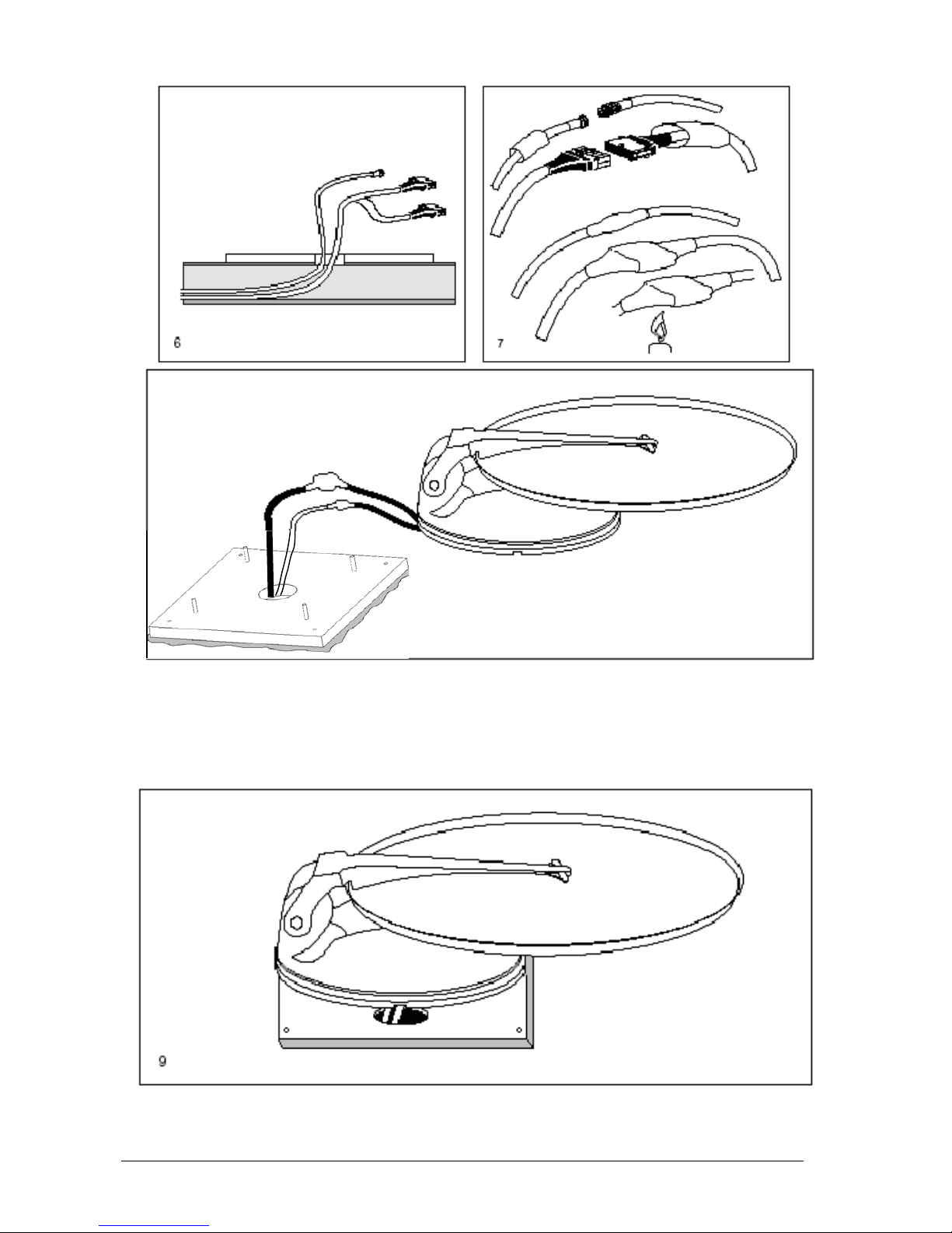
• After checking that everything is in order, install the dish on the driving unit as follows:
1) Temporarily connect the Control unit to the driving unit through the grey motor cable
2) Power both the Control unit and the receiver using a battery
3) Press the Red button in the remote control and extend the dish support mast
4) Press the " STOP " button in the remote control to lock the mast in a vertical position.
5) Secure the dish to the mast and screw down the four supplied screws
6) Press the " DOWN " button in the remote control and lower the antenna
7) Disconnect the Control unit, the battery and install Magic Sat 2002A on the vehicle
Page 5
V006
Pag. 5
ASSEMBLY INSTRUCTIONS
1) Position the Control unit in a compartment near the TV set
2) Fix the MIR remote control Extension to a wall or your TV-set and connect it to the
Control Unit.
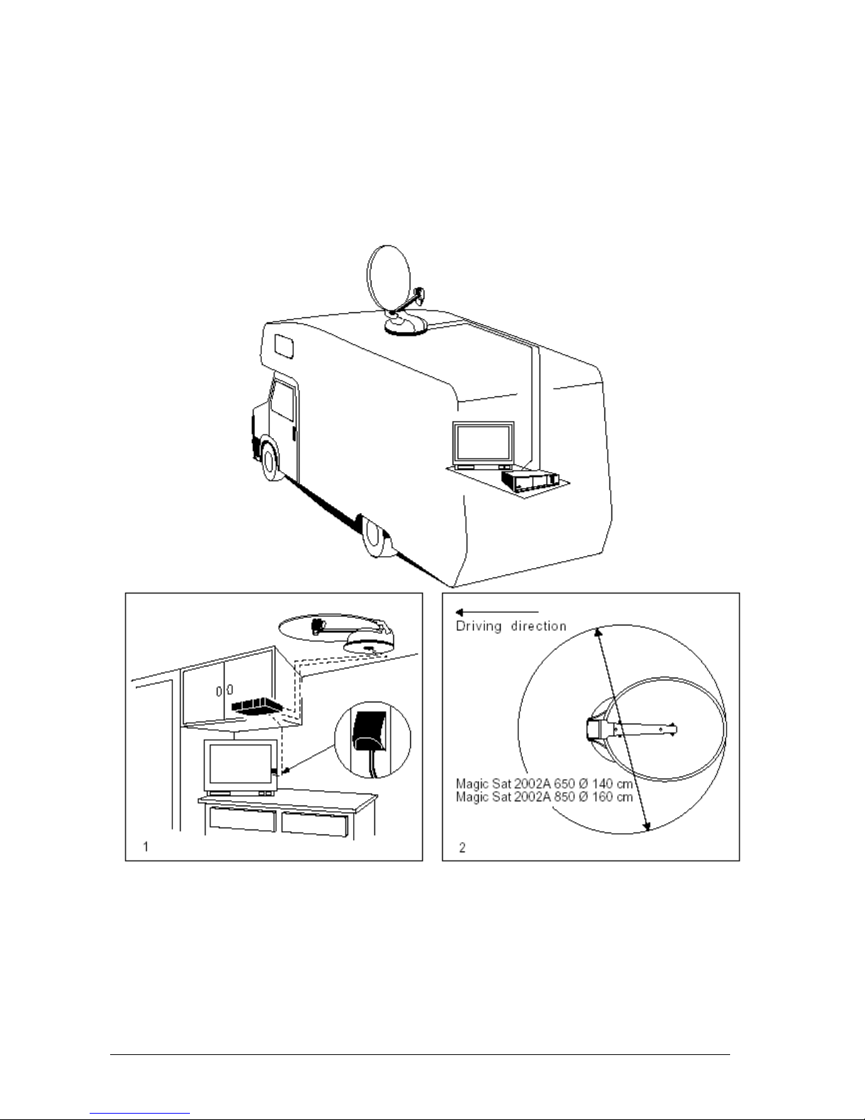
3) On the roof of the vehicle, choose a free area large enough to allow the antenna to
revolve (Fig. 2).
4) Install the (Grey and White) connection cables to reach the OUTDOOR UNIT
installation area..
5) Clean the roof carefully in the area the OUTSIDE UNIT is to be installed in.
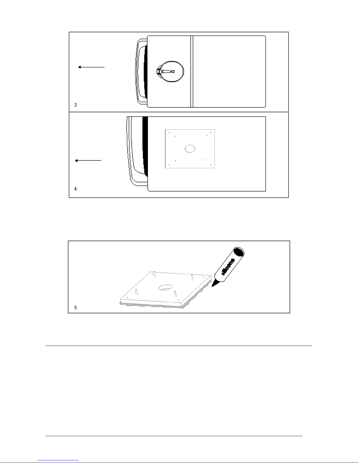
6) Remembering that the OUTSIDE UNIT must be fastened as shown on Figure 3, remove
the BASE PLATE from the outside unit, unscrewing all 4 nuts. Position the base plate
as Fig.4 with the short side towards the driving direction of the vehicle (Fig. 4).
Page 6
V006
Pag. 6
Driving direction of
the vehicle
Driving direction of
the vehicle
7) Clean the lower part of the BASE PLATE carefully, applying a layer of glue on the whole
surface (e.g. SIKAFLEX)
8) Fasten the Base Plate to the roof (short side towards the driving direction of the vehicle)
and fasten the 4 fastening nuts, applying silicone in the screw holes.
9) Apply a layer of silicone all around the BASE PLATE in order to make it completely
Installation with cables led through the middle of the base
10) Connect the Grey and White cables coming from inside the vehicle (Fig. 6) to both
cables of the outside unit, making them watertight using two pieces of
THERMORETRACTILE TUBE (Fig. 7).
WARNING
While performing this operation, do not pull forcefully on the cables coming from the
middle of the outside unit, in order not to risk pulling them out.
Page 7
V006
Pag. 7
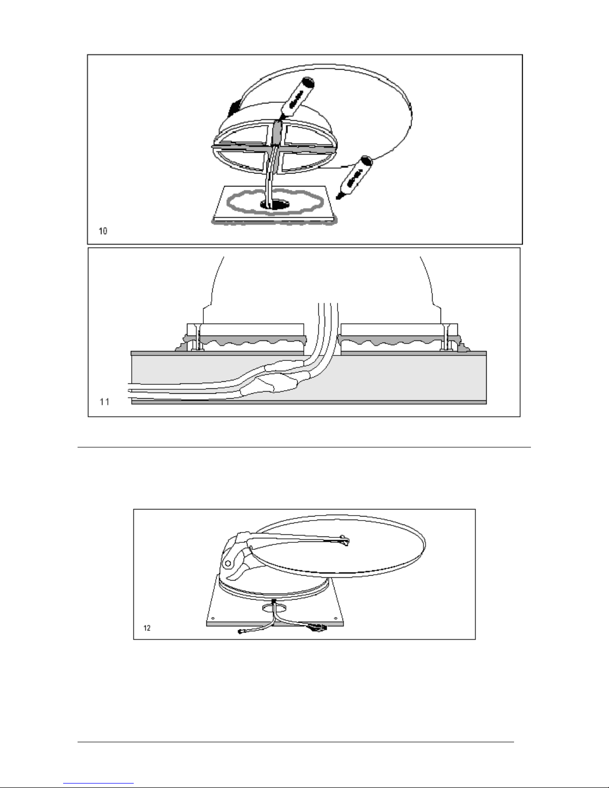
11) Install the OUTSIDE UNIT on the plate, bearing in mind that:
a) The proper position must be as in ( Figure 9 )
b) Coat both the base plate and the driving unit bottom ( Fig. 10 ) with a thick layer of
silicone to prevent any water infiltration. Screw in the four supplied nuts at the screws
and tighten as required ( Fig. 11
).
Page 8
V006
Pag. 8
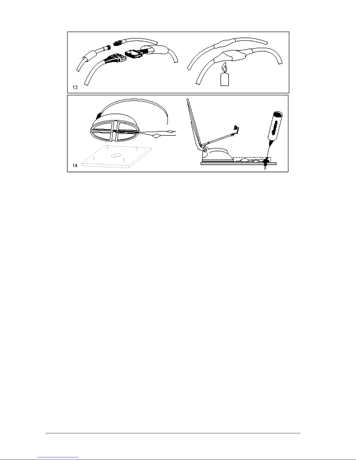
Installation with lateral cable output
12) Fasten the OUTSIDE UNIT to the base plate. Lead both cables out of the 4 grooves
and respect the positions shown on Figure 12.
CAUTION: during this operation, do not pull either cable forcibly, as they could come out.
13) Connect both cables coming from the centre of the OUTSIDE UNIT to the extensions.
Waterproof the connectors using both pieces of heat-shrinking pipe.
Page 9
V006
Pag. 9
14) Fit the cables into a fairlead skintop to the point where the cables enter the vehicle.
15) Carefully seal the fairlead skintop where the cables pass into the vehicle to prevent
water from coming in.
Page 10
V006
Pag. 10
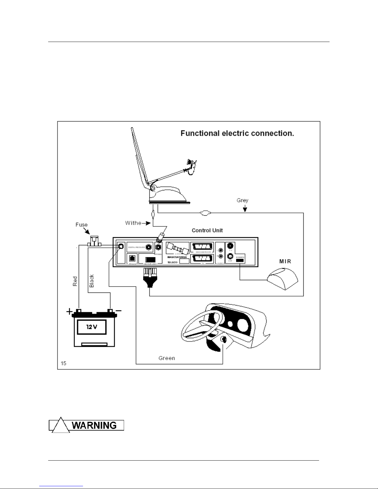
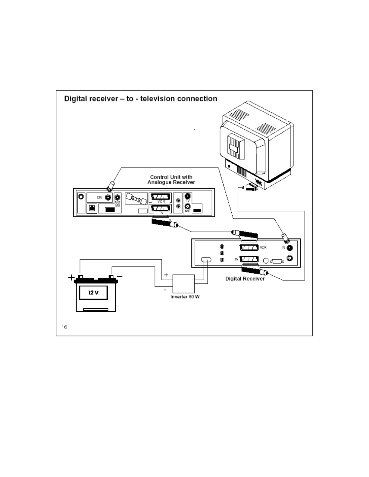
CONNECTIONS
16) Connect the (motor) grey cable to the MOTOR UNIT Connector and the white
(antenna) coaxial cable to the ANTENNA Connector in the Control
17) Connect the Digital Receiver (if any) to the DIGITAL RECEIVER connector.
18) Connect the MIR remote control Extension to the IR REMOTE connector in the Control
Unit
19) Connect the BLACK power supply cable of the CONTROL UNIT to the NEGATIVE
POLE of the vehicle 12 Volt battery, and the RED cable to the POSITIVE POLE + (
remember not to mix the + and - poles up ), using 2 cables of a diameter of 2.5 mm ( 5
mm2 cross-section).
20)
The GREEN safety cable of the Control Unit must be connected to the consensus of
the vehicle startup console (in many cases such consensus is located on Pin 15 in the
main terminal board). In this way, whenever the motor is started, this cable receives a
positive + 12 Vdc voltage, which will automatically lower the antenna and lock all
functions of the Control Unit simultaneously (Fig.15).
Any connection made in points other than as indicated (e.g. on
the alternator) can give rise to equipment malfunction and/or damage resulting in loss of
the warranty.
Page 11
V006
Pag. 11
21) Inside the Control Unit are:
a) Control ELECTRONICS of the outdoor unit motors
b) 500 Channel Analogue Receiver
c) Automatic Switch with Input for Digital Receiver
Page 12
V006
Pag. 12
This technical note is to call the attention of the installation personnel to certain details of
Magic Sat 2002A installation. During installation, you must take the following precautions:
The power supply cable must come directly from the battery and be of a minimum crosssection of 5 sq.mm. Only the Magic Sat 2002A must be connected to this cable; all the
other devices must be connected to another
The cable connecting the motor unit to the Magic Sat 2002A Control Unit must NEVER be
cut for any reason whatsoever; should the cable turn out to be too long, wind the extra part
into a coil in a free area of the vehicle. Leave a little cable in the motor unit area; should
any technical operation be required, it will make it easier to remove the motor unit.
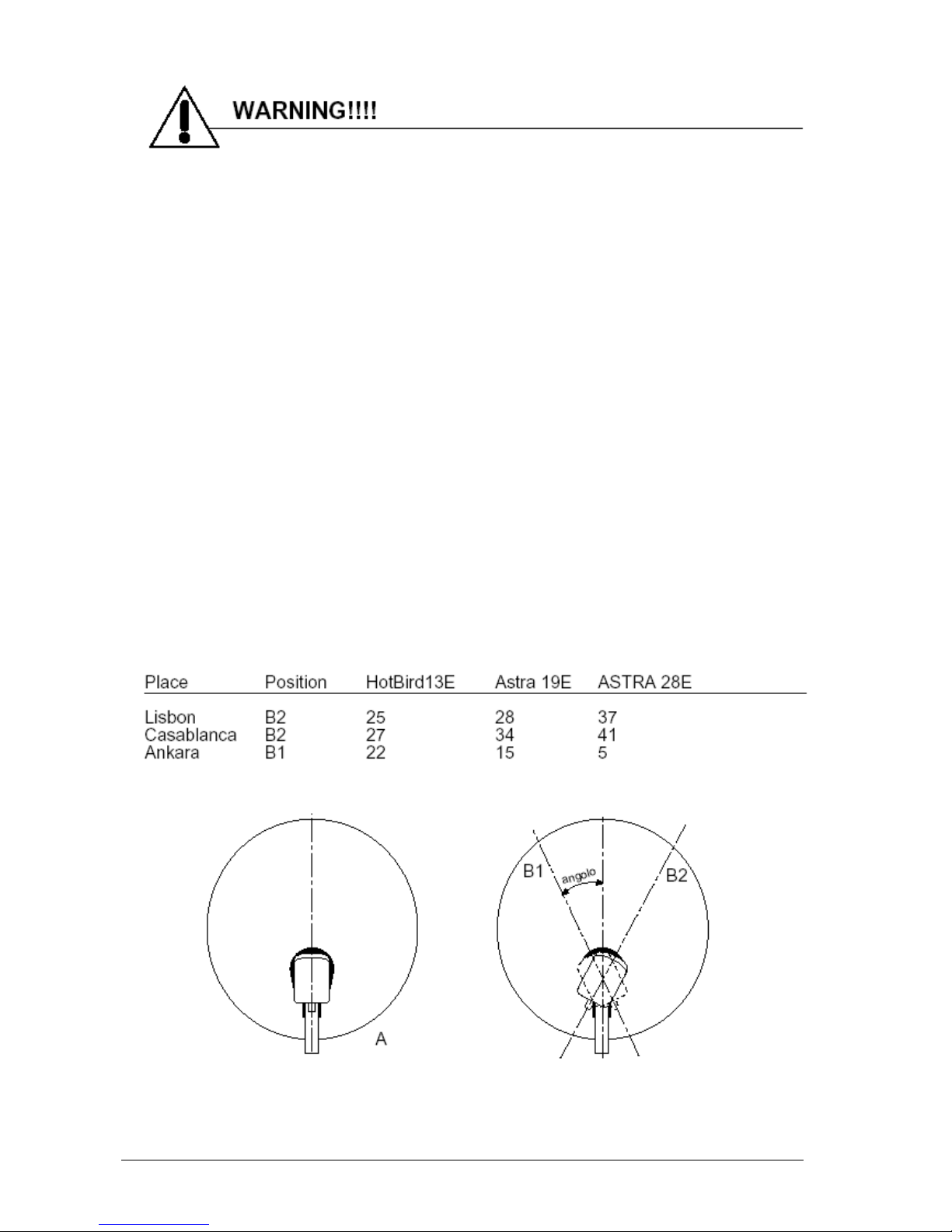
Also, before checking its operation, we suggest you make sure that:
the outside converter (a.k.a. LNB) has been installed properly and locked into its plastic
lock nut. Remember that the outside converter has its own assembly position which must
be complied with. Otherwise you will not receive any signal. The pre-set mounting position
for the converter is along the centre line of the disk (see figure A). With this configuration,
the MagicSat Digital system works correctly in most European countries. However, if you
are in areas very far from the satellite orbital position, it might be necessary to adjust the
converter angle. In particular, if you wish to receive transmissions from the satellites Astra
19E, Astra 28E or HotBird 13E, while you find yourself in Portugal or Morocco, your
converter angle should be adjusted as shown in figure B2, while if you are in Turkey, to
receive the same satellites you should set your converter to the position B1. A chart is
attached which may help you set the ideal angle.
Page 13

V006
Pag. 13
USER MANUAL: Magic Sat 2002A Operation System
Magic Sat 2002A is a fully automatic satellite pointing system, designed to point both
satellites which transmit ANALOGUE/DIGITAL signals (e.g. ASTRA or Hot Bird) and
satellites which transmit DIGITAL signals only (e.g. Astra 2). All operating information is
displayed on your TV screen when the system is
To ensure user-friendly operation, we have simplified these basic functions as
• satellite searching
• antenna lowering
• required program searching
Satellite seeking
When Magic Sat 2002A is off (Antenna down), press the Red button on the remote control
to start the searching procedure which will be completed when
Antenna lowering
When Magic Sat 2002A is on, and the antenna is up, press the (yellow) DOWN button to
bring the antenna down and switch the system off.
Programme seeking
Once the antenna has been pointed to the required satellite, radio and television stations
can be received by simply shifting programs with the remote control. To receive programs
from other satellites, you will just have to key in the number of your required program on
your remote control, or select it from the program list. MagicSat Digital will then search for
the next satellite and store the corresponding antenna position. If a digital bouquet is
requested instead of an analogue television/radio program (programs from 450 to 500),
the receiver will instruct the user on when to switch MagicSat Digital off and switch the
digital receiver on.
Thank you for having chosen our product. We wish you enjoy watching TV with Magic Sat
2002A.
Page 14
V006
Pag. 14
IMPORTANT INFORMATION for proper antenna pointing
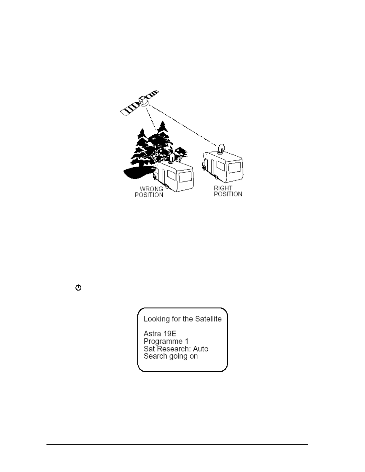
1) Before performing antenna pointing, make sure you have positioned your vehicle so the
view towards the South (where Satellite signals come from) is free from any nearby
obstacle (trees, houses, etc.). This way, the antenna will be free to receive signals
coming from the satellite.
2) It is also important to know that satellites do not transmit with the same intensity
throughout Europe, so if you are outside the reception area, your Magic Sat 2002A
search might be unsuccessful. The reception areas for each Satellite can be found on
the main magazines dealing in this line of business. Also remember that the larger the
dish, the more reception area
AUTOMATIC SATELLITE SEARCHING
1) Turn your TV set on and put it in a condition to receive signals coming from the satellite
receiver (See TV Manual).
2) Switch on the control unit by pressing the Red button on your remote control (or the
button on the front panel). The Magic Sat 2002A will also be automatically operated.
3) The following message will appear on your TV screen:
This message will remain until the antenna has identified the satellite. It tells you the name
of the satellite (e.g., Astra) which the Magic Sat Plus is looking for, and the programme
number (Programme 1) which will appear when pointing is over. Both these data are linked
to one another by a pre-storage on the receiver which has been performed in the factory in
the following order:
SATELLITE ASTRA 19°E ANNELS 1 - 62
SATELLITE TELECOM 2A 8°W CHANNELS 80 - 90
Page 15

V006
Pag. 15
SATELLITE TELECOM 2B 5°W CHANNELS 91 - 98
SATELLITE HOT BIRD 13°E CHANNELS 101 - 138
SATELLITE THOR 1°W CHANNELS 180 - 200
DIGITAL BOUQUETS CHANNELS 450 - 500
4) When the antenna points at a satellite during the seeking phase, the following message
will appear on your TV screen:
If it is the right satellite (e.g. Astra), the programme images will appear on the screen after
a few seconds have elapsed (e.g., Programme 1). If it is another satellite, then the antenna
will continue to seek, and the following message will be displayed again:
5) Once the antenna has been pointed to the required satellite, radio and television
stations can be received by simply shifting programs with the remote control. To receive
programs from other satellites, you will just have to key in the number of your required
program on your remote control, or select it from the program list. MagicSat Digital will
then search for the next satellite and store the corresponding antenna position. In this
way, shifting from one satellite to the next will be immediate. If a digital bouquet is
requested instead of an analogue television/radio program (programs from 450 to 500),
the receiver will instruct the user on when to switch MagicSat Digital off and switch the
digital receiver on.
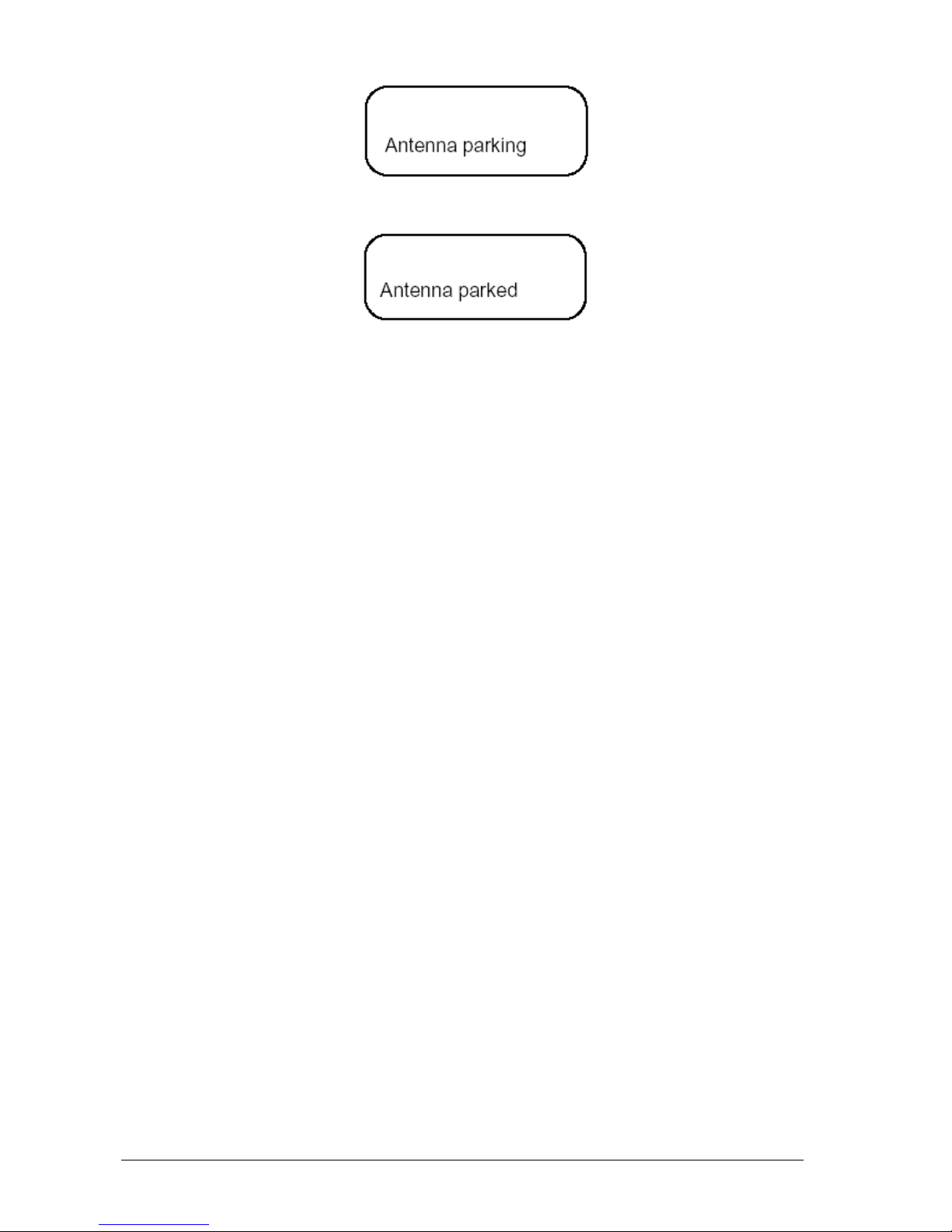
LOWERING THE ANTENNA
To bring the antenna to its horizontal position, just press your remote control DOWN
button to switch both the Receiver and Magic Sat 2002A off. During the short time it takes
for the antenna to come down, the following message will be displayed on the screen:
Page 16
V006
Pag. 16
Followed by:
When the antenna reaches its horizontal position, Magic Sat 2002A will go off and TV
messages will disappear. Should you forget to lower the antenna before starting up with
your road vehicle, don't worry: the moment you turn the engine ignition key, a special
safety circuit will lower the antenna automatically, keeping it locked in place as long as the
vehicle moves. This however is possible only if the special Green cable has been
connected to the ignition key at the time
N.B. Because of this safety function, remember that if you decide to turn the engine on in
order to charge the batteries of the vehicle, the Magic SatDIGITAL will automatically bring
the antenna down; as long as the engine is running, it will not be possible to perform
searching.
ADDITIONAL OPERATIONS
1) With the antenna pointed to a satellite, the Control unit may be turned off (by pressing
the Red push-button) without having to lower the antenna. In this case, the total
consumption by the system MAGIC SAT 2002A will be cut down to approximately 240
mA. To power the Control unit back on, just press the Red push-button on the remote
control once again.
2) If the antenna is in motion, the red push-button WILL NOT be working to prevent the
Control unit being switched off which would make satellite searching ineffective.
3) In the event that Magic Sat 2002A does not find the selected satellite, it will stop the
antenna at the end of its stroke (either all the way out or all the way in) and show the
message " No satellite " on the TV screen and " NSA" on the FP3412. If this happens,
the antenna can be lowered by pressing the DOWN push-button or a program
transmitted by another satellite can be selected.
Page 17
V006
Pag. 17
OPERATIONS FOR THOSE WITH GREATER EXPERTIS
Changing satellites during search
The Magic Sat Plus always starts its automatic search by examining the satellite which
transmits the last programme chosen before turning the system off (e.g. Astra, Channel 1).
Should you wish to launch an automatic search for another satellite, proceed as follows:
• Press the RED key on the remote control to swhitch on the system.
• Press the STOP key to stop the antenna temporarily (the words "Search suspended" will
be displayed on the TV set)
• Choose the new channel transmitted by the satellite you want (e.g. Channel 101, Hot
Bird)
• After a few seconds, the antenna will start searching again and will stop on the new
satellite (Hot Bird).
WARNING: if the antenna is stopped with the STOP button, this can only be restarted if a
programme transmitted by another satellite is selected.
Sequential satellite seeking
This kind of search is used only when you are at the edge of the reception area, where
signals are weaker, and only if Automatic Search has failed.
1 Turn the system on with the Red key
2 Interrupt the search pressing the STOP key
3 Press the MENU key
4 Choose CONFIGURATION
5 Choose SAT SEARCH
6 Choose SAT SEARCH: SEQUENTIAL using the key
7 Exit the MENU (See the Analogue Receiver instruction Manual)
8 Choose the programme you want (e.g.: 1)
At this point, the Magic Sat 2002A will start to search for the signal of the programme you
have chosen. When the antenna points at a satellite which transmits this signal, it will stop
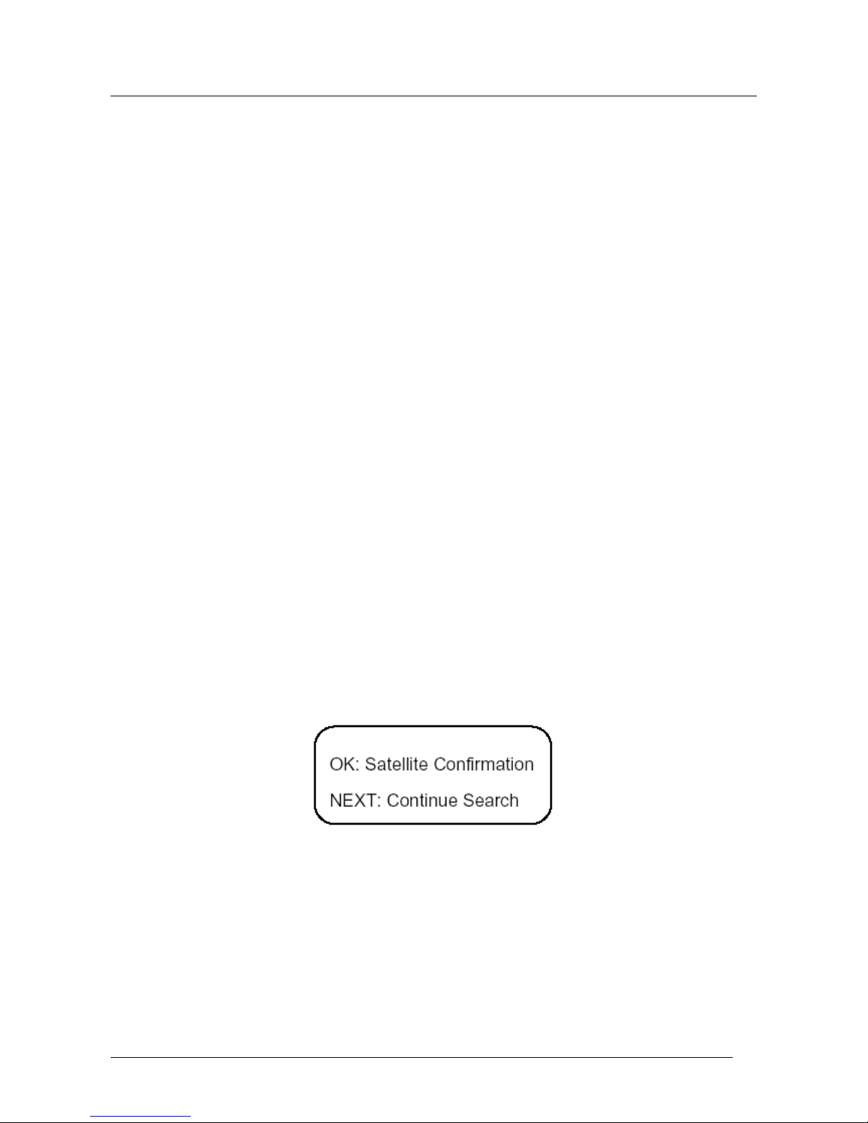
and the following message will be displayed:
Should the programme appearing on the TV set be the one that interests you, press the
OK key; otherwise, press the NEXT key to make the antenna search for another Satellite
which transmits the programme you want. The SEQUENTIAL SEARCH for the chosen
channel (e.g. Channel 1) could fail too. In this case, press the Down key again to lower the
antenna and turn the system off. Since satellites transmit some channels with high power
and others with lower power, in case of failure, you would do best to try another search
changing the number
1) Press the Red key to turn on
2) Press the STOP key to interrupt the search
Page 18
V006
Pag. 18
3) Choose a different channel number (e.g. 15), still however belonging to the group
transmitted by the satellite you want (in this case, Astra)
4) After a few seconds, Magic Sat 2002A will start seeking for the chosen channel
(channel 15) and will repeat the steps listed above.
SAFETY FUNCTION
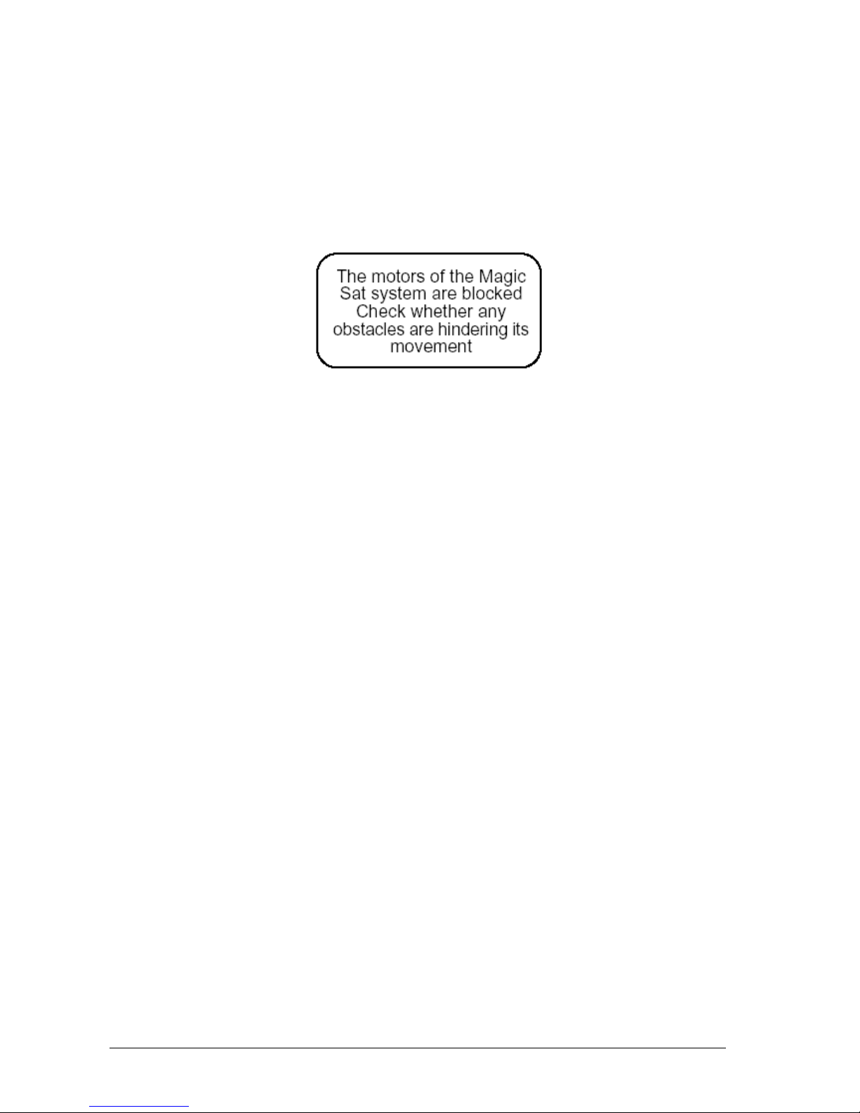
If, for any reason (trees, ice, etc.), the antenna is not able to move freely during the
operation, it will stop at once and the following message will be displayed:
After having verified the reason for the blockage, press the DOWN key and then remove
the cause.
TIPS on the best use of Magic Sat 2002A
When you park your vehicle, make sure that:
1) The view towards the South is free of any nearby obstacles. Any obstacle (trees or
buildings) between the satellite and the antenna prevent proper
2) No obstacle (for example trees) is too near your antenna, preventing it from moving
freely. No metal or glass wall is very near (about 5 m) the antenna, since this would act
as a mirror for satellite signals and could induce the antenna to point towards it.
3) In case of snow or ice actuating the Magic Sat 2002A free it in order to avoid wasting
battery power in order to lift it.
4) If you decide to turn the engine of your vehicle on in order to re-charge its batteries, with
the safety cable connected to the ignition key, the antenna, if lifted, will come down
automatically and it will not be possible to lift it again as long as the engine is running.
5) Make sure that your batteries are always sufficiently charged, since, if the voltage falls
below 10 Volts, the Magic Sat Digita electronic safety circuit will prevent the antenna
from rising.
6) Should you use 12 Volt feeders instead of batteries in order to feed the Magic Sat
2002A, be careful to use high quality stabilized feeders with a supplied power of at least
10A. At all costs, avoid using low quality, non stabilized battery feeders.
TROUBLE-SHOOTING
If the Magic Sat 2002A has not found the satellite after a complete search,
:
a) Is the view towards the South free from any obstacle?
b) Is the place you are at within the reception area of the satellite you have chosen?
c) Is the cable connecting the LNB to the antenna firmly fastened? It could have been
ripped off or come loose because of contact with an unexpected
d) Are all the connections on the Control Unit properly set up?
Page 19

V006
Pag. 19
If the antenna has stopped after performing pointing, but neither messages nor images
appear on the screen:
a) Is the SCART cable connected?
b) If the TV set is not connected by a SCART cable, but is connected by a COAX cable to
the TV socket, have you chosen the right programme on
If the antenna does not move when you press the Red push-button, check the
a) Are the RED and BLACK cables properly connected to the battery? The RED cable
must be on the + pole, the BLACK cable on the - pole.
b) Should you have mixed up the cables, first disconnect them, replace the safety fuse on
the bottom of the Control Unit using a similar one (10 A), then re-connect the RED and
BLACK cables properly to the battery.
c) Is the engine on your vehicle running? Turn it off, since this means the safety system
which keeps the antenna down is operating.
USER'S MANUAL: For the Analogue Receiver integral with the control
unit
Control Unit Front Panel
1) Transparent front panel with 3-digit display and remote control sensor.
2) Channel selection keys.
3) Instrument on/off key. When the instrument is off, a horizontal line is displayed.
Control Unit Rear Panel
Page 20
V006
Pag. 20
1) Connection cables to the 12V Battery
2) Connector to connect a Digital Receiver to Magic Sat 2002A
3) Connector to connect to the Magic Sat 2002A LNB
4) Connector to connect the (optional) FP3412 control extension
5) Connector to connect the Magic Sat 2002A Motor cable
6) SCART outlet for connection to VCR or DECODER units
7) SCART outlet for TV connection
8) AUDIO R-L outlets for HI-FI stereo connection
9) Connector to connect the control unit to a TV-set not equipped with any SCART outlets.
The Output channel is set to CH 21 and can be tuned to anything from 21 to 69, as you
may choose, using the remote control.
10) Connector to connect one terrestrial antenna
11) Connector to connect the MIR remote control extension (supplied).
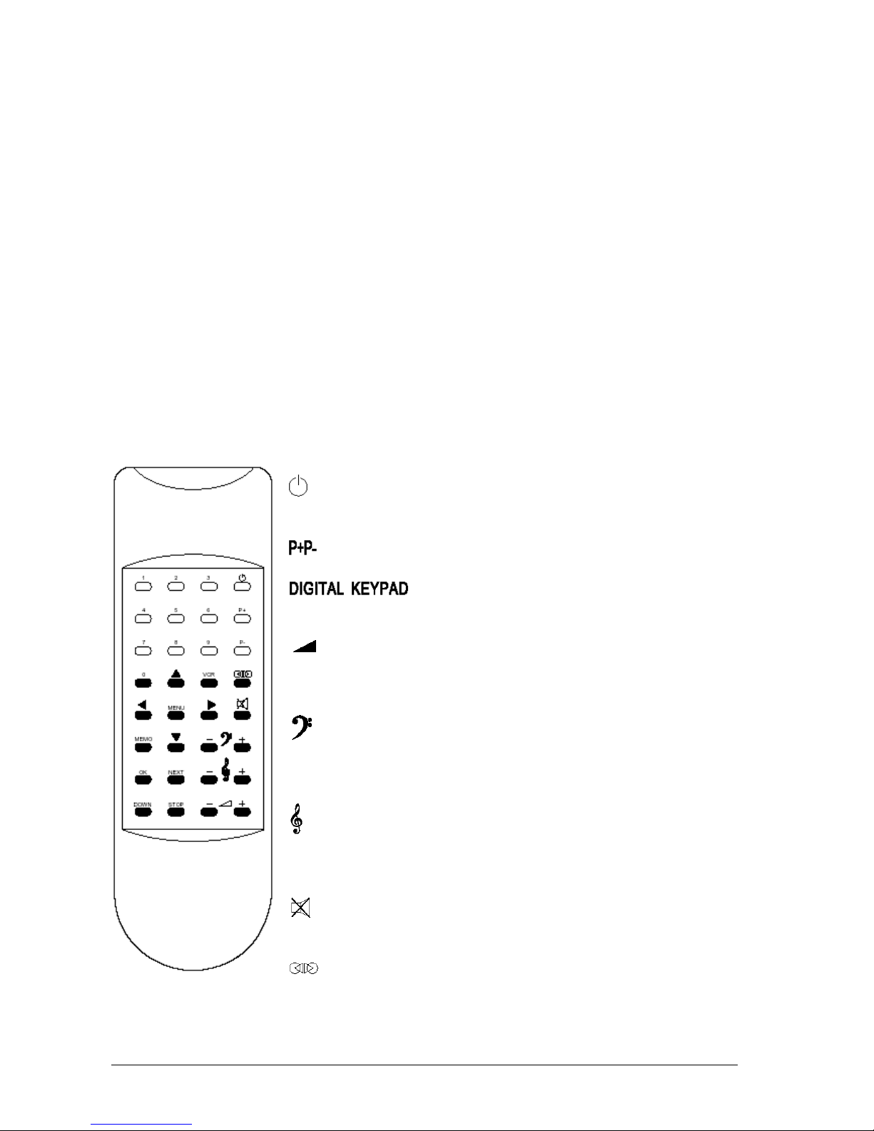
REMOTE CONTROL MAGIC SAT 2002A
This remote control can be used to control all the functions of Magic Sat 2002A and the
Analogue Receiver built in the Control
Main functions
Control Unit instrument is off, a horizontal line remains lit on
the display. When the receiver is switched on, the program
Analogue Receiver Program up/down
Used to directly enter the number of the
program that you wish to select.
Volume control. A value in the range 0/100 will be visible on
the TV screen at the time of operation. During this period
alterations can be made to the sound
Bass control. A value in the range -15/+15 will be visible on
the TV screen at the time of operation. During this period
alterations can be made to the sound
Treble control. A value in the range - 15/+15 will be visible on
the TV screen at the time of operation. During this period
alterations can be made to the sound
MUTE control. Press to turn off sound. The TV screen will
show AUDIO MUTO, the display will show MUT.
SPATIAL STEREO selection. By pressing this key you will
increase the stereo effect. SUONO SPAZIALE (SPACE SOUND) will be displayed on
Page 21

V006
Pag. 21
By pressing this key you will disconnect the TV from the SCART connector to allow
its normal operation. Press when you wish to record a satellite program and use your
television set to receive a terrestrial
It is used to display the SAT receiver MENU on your TV screen.
These two keys are used to scroll up/down the various MENU functions
These two keys are used to select any possible MENU value for each
Press key to store of the selected parameters.
This button can be pressed to enter the antenna position, if Magic Sat 2002A
sequential operation had been selected.
This button can be pressed to continue satellite searching during Magic Sat 2002A
sequential operation.
Key used to lower the antenna in the MAGIC SAT PLUS system
This button can be pressed to STOP SATELLITE SEARCHING in Magic Sat 2002A.
The antenna remains stopped until a programme transmitted by a satellite different from
the initial search satellite is selected. E.g. Magic Sat 2002A begins searching for the
programme No. 1 of ASTRA; by pressing STOP, search is interrupted, if for example the
programme No. 101 of EUTELSAT 13° is selected, the antenna. Begins a search for the
new satellite.
Page 22

V006
Pag. 22
ON SCREEN DISPLAY
Page 23

V006
Pag. 23
• The ON SCREEN DISPLAY is used to display all the satellite receiver functions on the
TV screen.
By pressing the key, the TV screen will show
• This is the MAIN MENU including all the functions that can be controlled on the receiver.
The arrow
is a pointer used to select the function to be modified. Which can be scrolled
vertically from one line to the next using the two remote control keys
. Each of the
MAIN MENU functions is divided into one or more subfunctions that are selected by
placing the arrow at the height of the required function and by pressing the key.
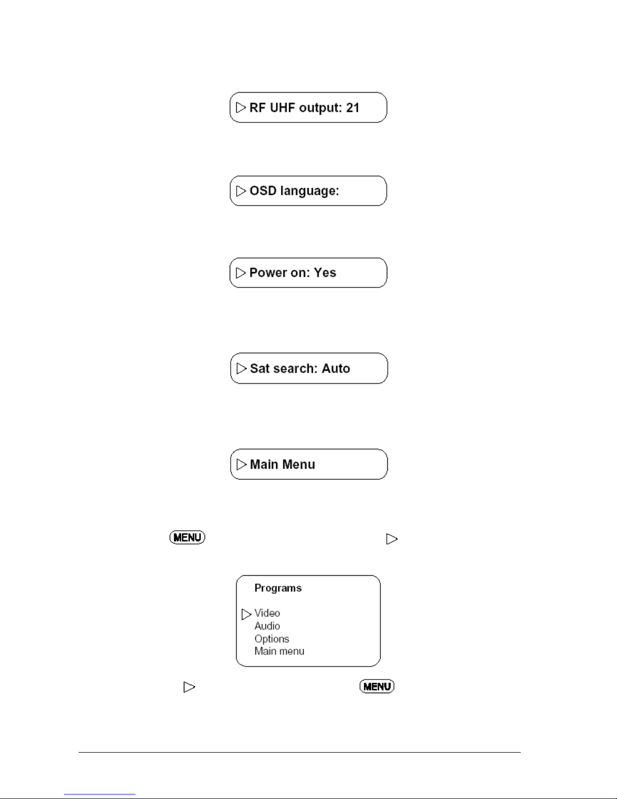
SUBFUNCTIONS
1) Configuration
Place the screen arrow to indicate the Configuration function using the keys .Then
press the key to obtain screen displaying the following subfunctions which are
factory-preset during testing:
• To modify the subfunction values, place the arrow at the height of the required line
using the keys then use the keys to select the required value.
• This subfunction is used to change the local oscillator values by + or – 7 Mhz on the
UNIVERSAL LNB used. LNB1 refers to the low band (10.7 - 11.7 Ghz) of the UNIVERSAL
LNB while LNB2 refers to the high band (11.7 - 12.75 Ghz). This variation allows the
receiver local oscillator value to be adjusted to the UNIVERSAL LNB value in case of
Page 24
V006
Pag. 24
oscillator departure from the rate value (9.75 Ghz for the low band, 10.6 Ghz for the high
band).
• This subfunction is used to set the modulator output channel (if installed). The available
values range from channel 21 to channel 69. During testing, channel 21 is present.
• It is used to select the required MENU language. The available options are Italian,
English, French, German.
• This is a special subfunction to allow the receiver to be switched back on (or NOT) to the
selected channel when input voltage is restored after a temporary cutoff. If NO is selected,
the receiver will remain in standby when voltage input is restored.
• This function is only active if the receiver is connected to the Magic Sat Plus control logic
board. This board allows the required type of satellite search to be selected on the Magic
Sat Plus system (either AUTOMATIC or SEQUENTIAL).
• Select to go back to the MAIN MENU.
2) Programs
• By pressing the
key after having brought the arrow to indicate MAIN MENU
programs, the following screen display will be obtained:
• Position the arrow to indicate Video and press the key to obtain the follow
screen display:
Page 25

V006
Pag. 25
• Select either LNB1 or LNB2 with the corresponding values on display.
LNB1 Low band UNIVERSAL LNB (10.7 - 11.7 GHz)
LNB2 High band UNIVERSAL LNB (11.7 - 12.75 Ghz) with 22 Khz tone
• This shows the selected program frequency transmitted from the satellite. Which can be
modified by directly entering a figure through the digital keypad or by pressing the keys
• This shows the polarization of the transmitted signals. Either H (horizontal) or V (vertical)
can be selected.
• This is used to select 6 different operation modes of the DECODER on its special
SCART outlet, through the keys
None: VCR operation
Vid.neg.: Operation with DECODER for C Band (inverted video)
Vcrypt1-2: Operation with DECODER Videocrypt 1-2, RAI, RTL4, RTL5
D2 - MAC: Operation with DECODER D-MAC, D2-MAC
Cplus<2>: Operation with DECODER Canal Plus (baseband signal with internal audio
passage)
• This is used to modify video level (High/Low).
Page 26

V006
Pag. 26
• Enables to return to Program Menu or ADR (for ADR model only).
• Position the arrow to indicate Audio and press the key to obtain the following
screen display
• Either Stereo or Mono can be selected
• This displays the audio frequency of the selected program, which can be changed from
5.00 to 9.50 MHz by 10 KHz steps.
• This displays the audio band of the selected program. In the STEREO MODE and MONO
you can select: 130 - 280 - 380 KHz
• In ADR mode, selection is automatic.
• 4 Deemphasizing selections are available: 50µs - 75µs - J 17 - Expander. The
EXPANDER MODE is particularly suitable for HI-FI reception of Stereo programs.
• When you return to the PROGRAM MENU, the subfunction Options are not active. Select
Quit Menu to return to the MAIN MENU.
• In ADR mode, selection is automatic.
• This is used to return to the Program Menu.
• Position the arrow to indicate Options and press the key to obtain the
following sceen display:
Page 27

V006
Pag. 27
• This function enables to associate the name of the program being viewed with the name
of the transmitting satellite. Use the arrow keys to select the required satellite. After
returning to the Program Menu select:
3) Clock
• Position the arrow
to indicate Clock and press the key to obtain the following
screen display:
• Position the arrow to indicate Year using the keys then change the entry with
the keys Repeat the same procedure for all the other data.
• All the values are automatically turned active when Main Menu is selected.
• After returning to MAIN MENU, position the arrow
to indicate Clock Events and press
the key
to obtain the following screen display:
• This function is used to program receiver power on/off in 8 events by choosing from
several options:
Page 28

V006
Pag. 28
• An event number from 1 to 8 is selected using the keys
• This is used to select the following event types with the keys Not active: storage not
on.
Daily: This is used to program receiver power on/off Every Day at the selected time.
Weekly: This is used to program receiver power on/off Every Week on the selected
day and time.
Date/time: This is used to program receiver power on/off at a given Time of a given Day.
• By selecting all the timed programming functions are
disabled. This only applies to the selected event, therefore, if you wish to completely
disable all programming functions, you must select for Event
no.:1, no.:2, no.:3 .... no.:8.
• By selecting , you can use the keys and to select the
power-on time and the duration of receiver operation day by day, and in addition, the
number of the channel that you wish to see.
• By selecting you can use the keys and to select, in
the following order,
• Week day
• Power-on time
• Length of receiver operation
• Number of channel that you wish to see.
• By selecting you can use the keys and to select, in
the following order,
• Receiver power-on date
• Power-on time
• Length of receiver operation
• Number of channel that you wish to see.
• All Clock Event functions are automatically stored when they are selected, therefore, it is
not necessary to press the key on the remote control.
• The beginning time of each event can be selected by 15 minute steps, while the event
duration can be selected by one hour steps.
N.B.:To prevent unwanted receiver power-on, we recommend to select
in all 8 events, whenever you do not need to use Clock Events.
Page 29

V006
Pag. 29
In the event of a power failure lasting more than 30 minutes, Clock Event programming is
lost.
4) Deletes Sat position
a) Press this button to delete all the satellite positions that Magic Sat 2002A had
stored during previous searching.
5) PROTECTED MENUS YES
This function is factory-preset to (YES) to protect a few MENU functions against un-
recommended modifications by inexperienced users. If the user wishes to obtain access to
all the MENU functions, all he has to do is highlight the "Protected Menu" line and key in
number 1111 to change the
To revert to (YES), key in the same number again.
NOT RECOMMENDED for in-experienced users to try and modify the MENU settings.
6) Programme list
Every TV and RADIO programme stored in the receiver has been recorded. To choose the
programme you want, key in the number for the programme (e.g.341) directly without
entering the MENU; or else, press the key MAIN MENU, then put the on
Programme List and press again to display the programme list. Use the keis
to move back or forth on the list by 7 programmes at a time. Use the keys to choose
the programme you want. To confirm the choice, press the When a program is entered,
the antenna automatically turns to the satellite which broadcasts that program (e.g.
ASTRA – ADR).
Page 30

V006
Pag. 30
CONNECTING WITH DIGITALI RECEIVER
Connecting with FALCON 12
CAD / AS
Rec 1
Rec 2
LNB
TV
ANTENNA
SAT
VK2
SCART-SCART
FEMALE ADAPTOR
CONTROL
SCART
COAX
SUPPLIED SCART
COAX
COAX
POWER SUPPLY
Switch on your TV set and Magic Sat 2002A control unit,
makin
g
sure that the
Falcon 12 receiver is off ( on stand-by)
. Start your satellite search with your
automatic antenna, after search completion press the VCR button in your TELECO
remote control, the display will read VCR.
N
ow you can switch on the Falcon 12 digital receiver and start the pointed satellite
broadcast channel loading (
for the first installation only
); at the end of this
operation, you can select your desired program.
Page 31

V006
Pag. 31
Connecting with Mikro CI
Switch on your TV set and Magic Sat 2002A control unit, making sure that the
Mikro Digital FTA receiver is off (on stand-by)
. Start your satellite search with
your automatic antenna, after search completion press the VCR button in your
TELECO remote control, the display will read VCR.
N
ow you can switch on the Mikro Digital CI digital receiver and select your desired
p
rogram.
CAD / AS
Rec 1
Rec 2
LNB
TV
ANTENNA
SAT
CONTROL
SCART
COAX
SUPPLIED SCART
COAX
COAX
To reduce current absorption while the Mikro Digital
CI receiver is not being used, we recommend fitting a
monopolar switch on the positive input.
Page 32

V006
Pag. 32
Connecting with Mikro FTA
Switch on your TV set and Magic Sat 2002A control unit, making sure that the
Mikro Digital FTA receiver is o ff (on stand-by). Start your satellite search with
your automatic antenna, after search completion press the VCR button in your
TELECO remote control, the display will read VCR.
N
ow you can switch on the Mikro Digital FTA digital receiver and select your
desired program.
CAD / AS
Rec 1
Rec 2
LNB
TV
ANTENNA
SAT
VK2
SCART-SCART
FEMALE ADAPTOR
CONTROLLO
SCART
COAX
SUPPLIED SCART
COAX
COAX
To reduce current absorption while the Mikro
Digital FTA receiver is not being used, we
recommend fitting a monopolar switch on the
positive input.
Page 33

V006
Pag. 33
SPECIFICATIONS
VIDEO
Input frequency 920 to 2150 MHz
Impedance 75 Ohm
C/N static threshold < 6 dB
Input level -65 dBm / -30 dBm
IF bandwidth 27 MHz
Selectable Offset - 7 to + 7 Mhz by 1 Mhz steps
AUDIO
Audio frequencies 5 to 9.0 MHz
Mode Mono / Stereo / Panda Wegener-compatible
ADR ( on MSP5012 ADR )
IF bandwidth 130/280/380 KHz
De-emphasizing 50 µs / 75 µs / J 17
Controls Volume/Balance/Treble-bass/Space stereo
AV CONNECTIONS
TV SCART
Decoder/VCR SCART
Modulator CH 21-69 by PLL PAL G
MISCELLANEOUS
LNB Power supply 13 to 18 Volt / 300 mA
Switching tone 22 KHz
Input voltage 12 Vdc 20%
Absorbed current max 1.2 A
Dimensions (mm) 162 x 250 x 67
Weight (kg) 1.3
REMOTE CONTROL FUNCTIONS
Channel search Digital/sequential keypad
RF frequency Digital/sequential keypad
Audio frequency Digital/sequential keypad
Modulator channels (21-69) Sequential
Decoder selection Sequential
Mode (Mono/Stereo) Sequential
Audio bandwidth Sequential
De-emphasizing Sequential
Controls Volume, Balance, Tones, Mute, V/H,
22 KHz, ON-OFF
Page 34

V006
Pag. 34
CHANNELS LIST
ASTRA 19 E
1 ADR
2 ZDF
3 SAT1
4 RTL
5 N-TV
6 PRO SIEBEN
7 BAYERISCHES F
8 N 3
9 SUDWEST F.
10 MTV GERMANY
11 MDR
12 PREMIERE
13 3 SAT
14 VOX / SELL-A
15 RTL2
16 SUPER RTL
17 ARTE/DER KIND
18 KABEL1
19 H.O.T.
20 DSF
21 BR ALPHA
22 ORB
23 PHOENIX
24 HESSEN FERNSE
25 QVC GERMANY
26 BLOOMBERG G.
27 TM3
28 WDR
29 SUDWEST F/RP
30 TELECLUB
31 SKY SPORT 1
32 SKY SPORT 2
33 SKY SPORT 3
34 SKI ONE
35 SKI BOX OFF3
36 SKI NEWS
37 SKI PREMIERE
38 SKI MOVIEMAX
39 SKI CINEMA
40 NIKELODEON U
41 CARTOON NET.
42 DISNEY CH.
43 TV SHOP
44 QVC UK
45 UK HORIZONS
46 UK GOLD
47 MTV UK
48 VH1 UK
49 SCI-FI CH.
50 GRANADA PLUS
51 GRANADA BREEZ
52 CHANNEL 5
53 QUANTUM CH.
54 TROUBLE/BRAVO
55 RAPTURE TV
56 TV TRAVEL
57 LIVING/TV-X
58 ZEE TV
59 JSTV
60 CNN INTERNATI
61 CNBC EUROPE
62 BLOOMBERG
63 NATIONAL GEO
64 EUROSPORT
65 ---66 ---67 ---68 ---69 ---70 ----
EUTELSAT 10 E
71 EBU CHANNEL Z
72 EBS-EUROPE
73 EBS-EUROPE
74 EBS-EUROPE
75 EBS-EUROPE
76 EBS-EUROPE
77 EBS-EUROPE
78 TGRT
79 EBU CHANNEL W
80 EBU CHANNEL U
81 HERBALIFE BRO
82 NTV
83 INTERSTAR
84 RTS SAT
85 INTERSTAR
86 ----87 ----88 ----89 ----90 -----
HOTBIRD 13 E
91 RAI UNO
92 RAI DUE
93 RAI TRE
94 LIVE SAT
95 EUROSPORT
96 POLSAT 2
97 POLSAT
98 TV POLONIA
99 CANAL+POLSKA
100 BBC WORLD
101 FASHION TV
102 CNBC EUROPE
103 QUANTUM CH.
104 QUANTUM 24
105 USINGEN TVCSM
106 VIVA
107 VIVA 2
108 MTV 2
109 VOX
110 RTL7
111 DEUTCHWELLE
112 LA CINQUIEME
113 TV5 EUROPE
114 RING
115 BVN TV / FUTA
116 TVE INTERN.
117 CANAL 24 ORA
118 DUNA TV
119 MED TV
120 TRT - INT
121 CANAL+HORIZ.
122 ANN ARAB NEWS
123 MBC
124 EDTV
125 ERT SAT
126 JAAM-E-JAM TV
127 RTP INTERN.
128 ....
129 ....
130 ....
EUTELSAT 16 E
131 RTM1
132 TVSH
133 ALGERIAN TV
134 TV CRNA GORA
135 BHT SAT/KTV T
136 TV 7
137 SAT-7
138 SYRIA TV
139 JAMAHIRYA SAT
140 TV MONTENEGRO
141 NILE TV INTER
142 JSC - AL JAZE
143 ESC 1
144 .....
145 .....
146 .....
147 .....
148 .....
149 .....
150 .....
31
SIRIUS 5.2 E
151 VIASAT PLUS
152 TEST
153 VH-1 SCANDINA
154 NIKELODEON S
155 Z TV
156 HALLMARK NORD
157 TV 4
158 TRAVEL
159 TV6
160 PLAYBOY TV
161 QUANTUM
162 TV 3
163 MTV NORDIC
164 CYPRUS SAT
165 VIASAT SPORT
166 TV 8
167 KANAL 5
168 .....
169 .....
170 .....
ATLANTIC BIRD 3 - 5 W
171 TF1
172 FRANCE 2
173 FRANCE 3
174 ARTE / LA 5EME
175 M6
Page 35

V006
Pag. 35
176 FEED
177 FEED
178 FEED
179 FEED
180 FEED
181 FEED
182 .....
183 .....
184 .....
185 .....
186 .....
187 .....
188 .....
189 .....
190 .....
TELECOM 8 W
191 CINE CINEMA 1
192 CINE CLASSIC
193 CANAL PLUS
194 FRANCE TELEC
195 FRANCE TELEC
196 FRANCE TELEC
197 FRANCE TELEC
198 FRANCE TELEC
199 FRANCE TELEC
200 FRANCE TELEC
201 FRANCE TELEC
202 ....
203 ....
204 ....
205 ....
206 ....
207 ....
208 ....
209 ....
THOR 1 W
210 TV DANMARK
211 TV2 NORGE
212 CANAL+NORGE
213 NRK TO
214 KANAL 5
215 NRK 1
216 QUANTUM 24
217 TV NORGE
218 DR 2
219 SKI NEWS & NAT.
220 TV3+
221 TV 1000 CINEMA
222 CARTOON NETWORK
223 TV 1000
224 TV3 NORGE
225 TV3 DANMARK
226 CNN NORDIC
227 TV2 NORGE
228 TV3 SVERIGE
229 BBC PRIME
230 FOX KIDS
231 EUROSPORT NORDIC
232 DISCOVERY CHAN.
233 CANAL + GUL
234 CANAL + SVERIGE
236 ....
237 ....
238 ....
239 ....
240 ABU DHABI TV
241 ....
242 ....
243 ....
244 ....
245 JSC
246 ....
247 ....
248 ....
249 ....
250 ....
RADIO ASTRA 19 E
251 ANTENNE BAYER
252 DEUTSCHEWELLE
253 DEUTSCHLANDFU
254 DEUTSCHLANDRA
255 EINS LIVE
256 EVOSONIC
257 KLASSIK RADIO
258 MDR SPUTNIK
259 N-JOY RADIO
260 NDR 2
261 NDR 4 INFO
262 RADIO EVIVA
263 RADIO HOREB
264 RTL RADIO 1
265 RTL RADIO 2
266 SWR 3
267 WDR 2
268 WRN 3
269 ANTENNE BAYER ADR
270 ANTENNE BRAND ADR
271 ARD-S1 ADR
272 B5 AKTUELL ADR
273 BAYERN 1 ADR
274 BAYERN 2 ADR
275 BAYERN 3 ADR
276 BAYERN 4 ADR
277 BREMEN 1 ADR
278 BREMEN 2 ADR
279 BREMEN 4 ADR
280 DAS DING ADR
281 DEUTSCHEWELLE ADR
282 DEUTSCHLANDF ADR
283 DEUTSCHLANDR ADR
284 DRS 1 ADR
285 DRS 2 ADR
286 EINS LIVE ADR
287 FRITZ ADR
288 RPR ZWEI ADR
289 HIT RADIO FFH ADR
290 HR1 ADR
291 HR1 PLUS ADR
292 HR2 ADR
293 HR2 PLUS ADR
294 HR3 ADR
295 HR4 ADR
296 HR XXL ADR
297 MDR INFO ADR
298 MDR KULTUR ADR
299 MDR LIFE ADR
300 MDR SPUTNIK ADR
301 MUSIGWALLE ADR
302 N-JOY RADIO ADR
303 NDR 2 ADR
304 NDR 4 INFO ADR
305 NDR 4 INFO SP ADR
306 PLANET RADIO ADR
307 RADIO 3 ADR
308 RADIO EINS ADR
309 RADIO EVIVA ADR
310 RADIO HOREB ADR
311 RADIO REGENBO ADR
312 RADIO 3 ADR
313 RADIOROPA ADR
314 ROCK ANTENNE ADR
315 RPR ZWEI ADR
316 SR1 EUROPAWEL ADR
317 SR2 KULTURRAD ADR
32
378 TRANSWORLD R
379 V.O.A.
380 RADIO ITALIA ADR
381 RETE UNO ADR
382 RADIO RUMANTC ADR
383 DW EURO 1&2 ADR
384 RADIO OSTERRE ADR
385 SWISS CLASSIC ADR
386 ....
387 ....
388 ....
389 ....
390 ....
SATELLITES LIST WITH
DIGITAL SEARCH
401 ASTRA 19E
402 ASTRA 28E
403 HOTBIRD 13E
404 EUTELSAT W3 7E
405 EUTELSAT 16E
406 THOR 1W
407 HISPASAT 30W
408 SIRIUS 5.2 E
409 ARABSAT 26E
410 NILESAT 7W
411 HELLASAT 39E
412 …
413 …
414 …
415 …
416 …
Page 36
MagicSat 2002A
(Tav. 1 - Vers. 10 del 07/10/2004)
Page 37

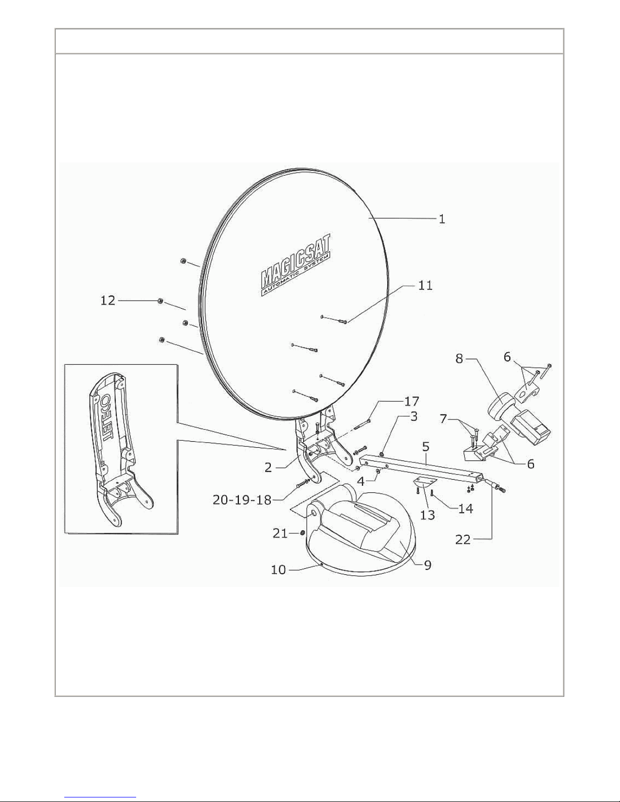
Pos Code Q.tà Descrizione/Description Dèsignation/Bezeichnung Denomination/Descripcion
1 03676 N.1 Disco parabola D=650mm
Parabolic antenna D=650 mm
Antenne parabole D=650 mm
Parabolspiegel D=650 mm
Schotel antenne D=650 mm
Disco parabola D=650 mm
1 07364 N.1 Disco parabola D=850mm
Parabolic antenna D=850 mm
Antenne parabole D=850 mm
PARABOLSPIEGEL D=850 mm
Schotel antenne D=850 mm
Disco parabola D=850mm
1 06681 N.1 Disco parabola D=500mm
Parabolic antenna D=500 mm
Antenne parabole D=500 mm
PARABOLSPIEGEL D=500 mm
Schotel antenne D=500 mm
Disco parabola D=500mm
2 08993 N.1 Braccio di sostegno Magicsat 500
Support arm Magicsat 500
Bras de support pour Magicsat 500
TRAGARM FUR MAGICSAT 500
Steunbeugel voor Magicsat 500
Brazo de soporte Magicsat 500
2 08992 N.1 Braccio di sostegno Magicsat 650/850
Support arm Magicsat 650/850
Bras de support pour Magicsat 650/850
TRAGARM FUR MAGICSAT 650/850
Steunbeugel voor Magicsat 650/850
Brazo de soporte Magicsat 650/850
3 06076 N.1 Boccola nylon
Nylon bush
Fourreau nylon
NYLONBUCHSE
Nylon bus
Casquillo nylon
4 05293 N.1 Passacavo gomma
Hole grommet
Passa-fil caoutchouc
KABELTULLE AUS GUMMI
Rubberen kabeldoorvoer
Pasacable coucho
5 08996 N.1 Tubo supporto LNB Magicsat 500 (SLNB45)
LNB Magicsat 500 support tube (SLNB45)
Tube support LNB Magicsat 500 (SLNB45)
LNB-HALTEARM FUR MAGICSAT 500
(SLNB45)
LNB draagarm van Magicsat 500
(SLNB45)
Tubo soporte LNB Magicsat 500
(SLNB45)
5 08994 N.1 Tubo supporto LNB Magicsat 650 (SLNB45)
LNB Magicsat 650 support tube (SLNB45)
Tube support LNB Magicsat 650 (SLNB45)
LNB-HALTEARM FUR MAGICSAT 650
(SLNB45)
LNB draagarm van Magicsat 650
(SLNB45)
Tubo soporte LNB Magicsat 650
(SLNB45)
5 08995 N.1 Tubo supporto LNB Magicsat 850 (SLNB45)
LNB Magicsat 850 support tube (SLNB45)
Tube support LNB Magicsat 850 (SLNB45)
LNB-HALTEARM FUR MAGICSAT 850
(SLNB45)
LNB draagarm van Magicsat 850
(SLNB45)
Tube soporte LNB Magicsat 850
(SLNB45)
6 03679 N.1 Supporto in plastica per LNB tipo Kombi
Plastic support for Kombi-type LNB comp let
Support en plastique pour LNB type Kombi
Kunststoffhalterung fur LNB typ Kombi,
Komplete
Plastic steun voor LNB type Kombi
Soporte plastico para LNB tipo Kombi
8 06923 N.1 LNB Stark T1
LNB Stark T1
LNB Stark T1
LNB Stark T1
LNB Stark T1
LNB Stark T1
9 05468 N.1 Coperchio motore
Engine cover
Capot moteur
Motordeckel
Motorkap
Tapa motor
10 05704 N.2 Rivetto in nylo n
Nylon rivet
Rivet en nylon
Nylonniet
Blindklinknagel nylon
Remache de nylon
11 05544 N.4 Vite 6MA20 testa cilindrica inox
Stainless stell cheese-headed screw 6MA20
Vis 6MA20 tete cylindrique inox
Zylinderschraube 6MA20 aus rostfreiem stahl
Schroef 6MA20 cilinderkop rvs
Tronillo 6MA20 cabeza cilindrica inox
11 07160 N.4 Vite M5x20 ISO7380
Screw M5x20 ISO7380
Vis M5x20 ISO7380
KOPFSCHRAUBE M5x20 ISO7380
Schroef M5x20 ISO7380
Tornillo M5x20 ISO7380
12 03685 N.4 Dado auto-bloccante M5 UNI7474 inox
Stainless steel self-locking nut M5 UNI7474
inox
Ecrou autobloquant M5 UNI7474 inox
Selbstsichernde Mutter M5 UNI7474 inox
Zelfborgende moer M5 UNI7474 inox
Tuerca de seguridad M5 UNI7474 inox
12 03684 N.4 Dado auto-bloccante D=6 inox
Stainless steel self-locking nut D=6
Ecrou autobloquant D=6 inox
Selbstsichernde Mutter D=6 Aus Rostfreiem
STA
Zelfborgende moer D=6 rvs
Tuerca de seguridad D=6 inox
13 06045 N.1 Culla nera
Black cradle
Berceau noir
TRAGER SCHWARZ
Wieg zwart
Apoyo negro
14 03722 N.2 Vite 4x10 testa cilindrica
Cheese-headed screw 4x10
Vis 4x10 tete cylindrique
ZYLINDERKOPFSCHRAUBE 4x10
Schroef 4x10 cilinderkop
Tornillo 4x10 de cabeza cilindrica
17 04441 N.1 Vite 6x60 MA testa esagonale inox
Stainless 6x60 MA steel hexagonal-head
screw
Vis 6x60 MA tete hexagonale inox
Sechskantschraube 6x60 MA aus rostfreiem
stahl
Schroef 6x60 MA cilinderkop rvs
Tornillo 6x60 MA cabeza hexagonal
inox
18 03149 N.2 Vite 8X30 inox
Stainless steel screw 8x30
Vis 6x30 inox
SCHRAUBE 6X30 ROSTFREIER STAHL
Schroef 8x30 rvs
Tornillo 8x30 inox
19 06020 N.2 Rondella D=8 piana inox
Stainless steel flat D=8 washer
Rondelle D=8 plate inox
SCHEIBE D=8 FLACH, AUS ROSTFREIEM
STAHL
Onderlegring D=8 plat rvs
Arandela D=8 plana inox
20 06038 N.2 Rondella 8 snor nera
Black 8 SNOR washer
Rondelle 8 snor noire
SCHEIBE B SNOR SCHWARZ
Onderlegring 8 snor zwart
Arandela 8 snor negra
21 05697 N.1 Guarnizione PG7
Gasket PG7
Joint PG7
Dichtung PG7
Afdichting PG7
Junta PG7
21 05696 N.1 Controdado
Lock nut
Contre-ecrou
Gegenmutter
Contramoer
Contratuerca
21 05695 N.1 Passacavo skintop PG7 V+ e VM atic
Fairlead skintop PG7 V+ and VMatic
Passe-fil skintop PG7 V+ et VMatic
Kabeltulle skintop PG7 V+ und VMatic
Kabeldoorvoer skintop PG7 V+ en
VMatic
Pasacable skintop PG7 V+ e VMatic
Page 38

MagicSat 2002A
(Tav. 2 - Vers. 10 del 07/10/2004)
Page 39

Pos Code Q.tà Descrizione/Description Dèsignation/Bezeichnung Denomination/Descripcion
13 06037 N.2 Guarnizione laterale
Side gasket
Joint lateral
SEITLICHE DICHTUNG
Zijafdichting
Junta lateral
20 04761 N.2 Microinterruttore a ten ut a stagna
Waterproof microswitch
Microcontact etanche
MIKROSCHALTER, DICHT
Microschakelaar in stor- en waterdichte uit
Microinterruptor estanco
23 04947 N.2 Motoriduttore
Gearmotor
Motoreducteur
Getriebemotor
Motorreductor
Motorreductor
24 05658 N.1 Basetta supporto connettori
Connector strip
Base de support pour connecteurs
KLEMMLEISTE FUR VERBINDER
Steunplaat connectoren
Base soporte conectores
27 05384 N.1 Piastra base
Base plate
Plaque de base
BASISPLATTE
Onderplaat
Placa de base
28 08997 N.1 Piastra di montaggio rettangolare
Assembly rectangular plate
Plaque de montage
Montageplatte
Montageplaat
Placa de sujecion
29 06900 N.1 Guarnizione O-SEALING VITON PG21
Gasket O-SEALING VITON PG21
Joint O-SEALING VITON PG21
Dichtung O-SEALING VITON PG21
Afdichting O-SEALING VITON PG21
Junta O-SEALING VITON PG21
29 06898 N.1 Controdado SKINTOP PG21
SKINTOP plastic nut PG21
Ecrou plastique SKINTOP PG21
Kunststoffmutter SKINTOP PG21
Moer plastic SKINTOP PG21
Tuerca plástico SKINTOP PG21
29 06901 N.1 Pressacavo SKINTOP PG21
SKINTOP cable gland PG21
Serre-câble SKINTOP PG21
Kabelschelle SKINTOP PG21
Kabelklem SKINTOP PG21
Prensacable SKINTOP PG21
Page 40

MagicSat 2002A
(Tav. 3 - Vers. 10 del 07/10/2004)
Page 41

Pos Code Q.tà Descrizione/Description Dèsignation/Bezeichnung Denomination/Descripcion
1 04437 N.1 Cornice frontale piccola
Small front frame
Cadre partie av. petite
Frontrahmen, klein
Kleine frontlijst
Marco frontal pequeño
2 04274 N.1 Serie tasti
Set of keys
Jeu de touches
Serie Tasten
Aantal toetsen
Serie teclas
2 04269 N.1 Frontale piccolo blu
Blue small front
Partie Av. petite bleue
Kleines Frontteil, blau
Klein front blauw
Frontal pequeño azul
3 04270 N.1 Frontale grande blu
Blue big front
Partie Av. grande bleue
Grobes Frontteil, blau
Groot front blauw
Frontal grande azul
4 04749 N.1 Frontale grande nero
Black big front
Partie av. grande noire
Grobes Frontteil, schwarz
Groot front zwart
Frontal grande negro
5 04748 N.1 Cornice lunga nera
Long black frame
Cadre long noir
Langer Rahmen, schwarz
Lange lijst zwart
Marco largo negro
6 01457 N.1 Scheda frontale display
Display front board
Carte partie av.afficheur
Display-Frontkarte
Frontprintplaat display
Tarjeta frontal pantalla
7 03574 N.1 Cavo interno flat per ricevitore
Receiver flat inner cable
Câble int. plat pour récepteur
Internes Flachkabel fur Receiver
Inwendige platte kabel voor ontvanger
Cable plano interno para receptor
8 07923 N.1 Eprom TSR 5012
TSR 5012 Eprom
Eprom TSR 5012
Eprom TSR 5012
Eprom TSR 5012
Eprom TSR 5012
9 07292 N.1 Scheda T0011 (rev.O)
T0011 board (rev.O)
Carte T0011 (rev.O)
Karte T0011 (rev.O)
Printplaat T0011 (rev.O)
Tarjeta T0011 (rev.O)
10 07924 N.1 Eprom MAGICSAT
MAGICSAT Eprom
Eprom MAGICSAT
Eprom MAGICSAT
Eprom MAGICSAT
Eprom MAGICSAT
11 05240 N.1 Fusibile ritard. 2,5A
Delayed fuse 2.5A
Fusible temporise 2,5 A
TRŽGE SICHERUNG 2,5 A
Zekering traag 2,5A
Fusible retard. 2,5
12 07888 N.1 Scheda T0069E
T0069E board
Carte T0069E
Karte T0069E
Printplaat T0069E
Tarjeta T0069E
13 07522 N.1 Fondo unita' comando
Control unit bottom
Fond boite/comm.
Boden Steuereinheit
Onderkant bedieningsunit
Fondo unidad de mando
14 07661 N.1 Coperchio unita' comando
Control unit lid
Capot boite/comm.
Deckel Steuereinheit
Kap bedieningsunit
Tapa unidad de mando
15 07786 N.1 Cavo connessione T0011-T0069
T0011-T0069 conn.cable
Câble connex. TT0011-T0069
Anschlusskabel T0011-T0069
Verbindingskabel T0011-T0069
Cable conexi•n T0011-T0069
16 07674 N.1 Commutatore
Commutator
Commutateur
Schalter
Omschakelaar
Conmutador
17 07798 N.1 Estensore di telecomando
Remote ctrl expander
Pann./comm.suppl. télécomm.
Fernbedienungs-Frontteil
Uitbreidingsmodule afstandsbediening
Extensor de mando a distancia
18 06009 N.1 Telecomando TSR5012
Remote control TSR5012
Telecommande TSR5012
Fernbedienung TSR5012
Afstandsbediening TSR5012
Telecomando TSR5012
19 03461 N.1 Passacavo
Fairlead
Serre-coble
Kabeldurchfuhrung
Kabeldoorvoer
Guía cabley
20 05733 N.1 Fusibile 7.5A
7.5A Fuse
Fusible 7.5 A
Sicherung 7.5A
Zekering 7,5A
Fusible 7.5A
21 05287 N.2 Connettore M/F 90ø
M/F 90ø connector
Connecteur M/F 90ø
Verbinder 90ø
M/F stekker 90ø
Conector M/F 90ø
22 07789 N.1 Connettore F doppio maschio
Double male F connect.
Connect.F double mâle
Doppelter F-Steckverbinder
F-stekker dubbel mannetje
Conector F doble macho
Page 42

MagicSat 2002A
(Tav. 4 - Vers. 10 del 07/10/2004)
Page 43

Pos Code Q.tà Descrizione/Description Dèsignation/Bezeichnung Denomination/Descripcion
1 08998 N.1 Cavo coassiale 2mt con connet. F/F
2 m coax cable F/F.connector
Cable coaxial 2 m avec connecteur F/F
KOAXIALKABEL 2 m MIT F-FVERBINDER
Coaxkabel 2 m inclusief F/F-connector
Cable coaxial 2mt con conect F/F
3 03598 N.1 Guaina termorestringente
Shrink-wrap sheath
Gaine thermoretractible
MANTEL, WARMESCHRUMPFEND
Krimpkous
Vaina termorretractil
4 03597 N.1 Guaina ternorestringente
Shrink-wrap sheath
Gaine thermoretractible
MANTEL, WARMESCHRUMPFEND
Krimpkous
Vaina termorretractil
5 07193 N.1 Cavo 10 poli 2mt contr. gruppo motore
con conn
10-core 2mt engine unit cont. cable
w/connecto
Cable 10 poles 2mt contr. groupe moteur
avec conn
10-POLIGES 2mt STEUERKABEL
MOTOREINHEIT
Besturingskabel motoreenheid 10-polig
2mt incl.
Cabla 10 polos 2mt contr. grupo motor
con con.
6 08864 N.1 Copri cavi abs bianco
Cable cover abs
Capot cable abs
Kabeldeckel abs
kapkabel abs
Tapa cables abs
7 05950 N.1 Cavo coassiale 3mt con connet. F/F
3 m coax cable F/F.connector
Cable coaxial 3 m avec connecteur F/F
KOAXIALKABEL 3 m MIT F-FVERBINDER
Coaxkabel 3m inclusief F/F-connector
Cable coaxial 3mt con conect F/F
7 07294 N.1 Cavo coassiale 5mt con connet. F/F
5 m coax cable F/F.connector
Cable coaxial 5 m avec connecteur F/F
KOAXIALKABEL 5 m MIT F-FVERBINDER
Coaxkabel 5m inclusief F/F-connector
Cable coaxial 5mt con conect F/F
7 07883 N.1 Cavo coassiale 9mt con connet. F/F
9 m coax cable F/F.connector
Cable coaxial 9 m avec connecteur F/F
KOAXIALKABEL 9 m MIT F-FVERBINDER
Coaxkabel 9m inclusief F/F-connector
Cable coaxial 9mt con conect F/F
8 08919 N.1 Cavo 10 poli 15mt contr. gruppo motore
con conn
10-core 15mt engine unit cont. cable
w/connecto
Cable 10 poles 15mt contr. groupe moteur
avec conn
10-POLIGES 15mt STEUERKABEL
MOTOREINHEIT
Besturingskabel motoreenheid 10-polig
15mt incl.
Cabla 10 polos 15mt contr. grupo motor
con con.
8 07267 N.1 Cavo 10 poli 3mt contr. gruppo motore
con conn
10-core 3mt engine unit cont. cable
w/connecto
Cable 10 poles 3mt contr. groupe moteur
avec conn
10-POLIGES 3mt STEUERKABEL
MOTOREINHEIT
Besturingskabel motoreenheid 10-polig
3mt incl.
Cabla 10 polos 3mt contr. grupo motor
con con.
8 07273 N.1 Cavo 10 poli 5mt contr. gruppo motore
con conn
10-core 5mt engine unit cont. cable
w/connecto
Cable 10 poles 5mt contr. groupe moteur
avec conn
10-POLIGES 5mt STEUERKABEL
MOTOREINHEIT
Besturingskabel motoreenheid 10-polig
5mt incl.
Cabla 10 polos 5mt contr. grupo motor
con con.
8 07266 N.1 Cavo 10 poli 9mt contr. gruppo motore
con conn
10-core 9mt engine unit cont. cable
w/connecto
Cable 10 poles 9mt contr. groupe moteur
avec conn
10-POLIGES 9mt STEUERKABEL
MOTOREINHEIT
Besturingskabel motoreenheid 10-polig
9mt incl.
Cabla 10 polos 9mt contr. grupo motor
con con.
Page 44

ITALY
Via E.Majorana 49
48022 LUGO( RA )
Tel. + 39 0545 25037
Fax.+ 39 0545 32064
Tel. Servizio Assistenza
899 899 856
E-mail: info@telecogroup.com
www.telecogroup.com
IN EUROPE:
GREAT BRITAIN - SCAN TERIEUR LTD
30, The Metro Centre, Tolpits Lane - Watford,
Herts - England - WD18 9XG
Tel. 01923 800353 - Fax 01923 220358
HOLLAND - KARMAN AGENTUREN
Emmastraat, 31
1213 AJ Hilversum - Holland
Tel. 035 6240156 - Fax 035 6242141
e-mail: karman.agenturen@worldonline.nl
FRANCE – BLEYS ANTOINE – BLEYS JEAN-PHILIPPE
19, Rue de la Parcheminerie
18700 Aubigny sur Nere - France
Tel. 02 48580367- Fax. 02 48583585
Mobil. 06 78262186 Mobil. 06 07012634
e-mail: bleysetd@club-internet.fr - jp.bleysetd@club-internet.fr
ESPAÑA - NAUCCA CARAVANING, S.A.
Poligono Industrial CAN ROQUETA 2 – Calle Can Lletget,2
08202 Sabadell (Barcelona) - España
Tel. 00 34 937 457 054 - Fax. 00 34 937 254 484
e-mail: comercial@naucca.com
ÖSTERREICH – TELECO GmbH
82041 Deisenhofen -
Tel. 08031 98939 - Fax. 08031 98949
e-mail: telecogmbh@telecogroup.com
www.telecogroup.com
IN DEUTSHLAND
TELECO GmbH
82041 Deisenhofen Tel. 08031 98939 - Fax. 08031 98949
e-mail: telecogmbh@telecogroup.com
www.telecogroup.com
Händler und Info in Ihrer Nähe:
01805 006857
Service für Teleco Anlagen in Deutschland:
09001000690
Foto e disegni non contrattuali - Les photos et les dessins ne sont donnés qu’à titre indicatif.
We reserve the right to make technical changes without prior notice - Fotos und Zeichnungen nicht vertraglich.
Foto’s en tekeningen niet contractueel - Fotos y planos no indicados en contrato
 Loading...