

Teleco Flat Sat Elegance Smart 50, Flat Sat Elegance Smart 65, Flat Sat Elegance Smart 85 Installation And Operation Manual
GB
Installation and
operation manual
TELECO WARRANTY
Teleco guarantees its satellite dishes and terrestrial antennas against any
material and/or construction fault and defect. The warranty offered by
TELECO is limited to the free-of-charge replacement or repairing of any
parts that are deemed faulty by TELECO. The warranty is applicable for a
period of 3 YEARS starting from the product purchase date; however, it will
only be considered valid if the Customer is able to produce a written document
(invoice or tax receipt) showing the purchase date.
The following is excluded from the TELECO warranty:
a. Damages caused by incorrect installation and/or use and/or maintenance
b. Damages resulting from product alterations not authorised by Teleco
c. Damages resulting from the use of spare parts different from original
Teleco parts
d. Damages resulting from repairs carried out by personnel not
authorised by Teleco
e. Normal part wear;
f. Expenses incurred for spare parts transport between the Customer's
and the service centre
g. Damages that may occur during transport:
the Customer shall always be responsible for transport risks.
Information
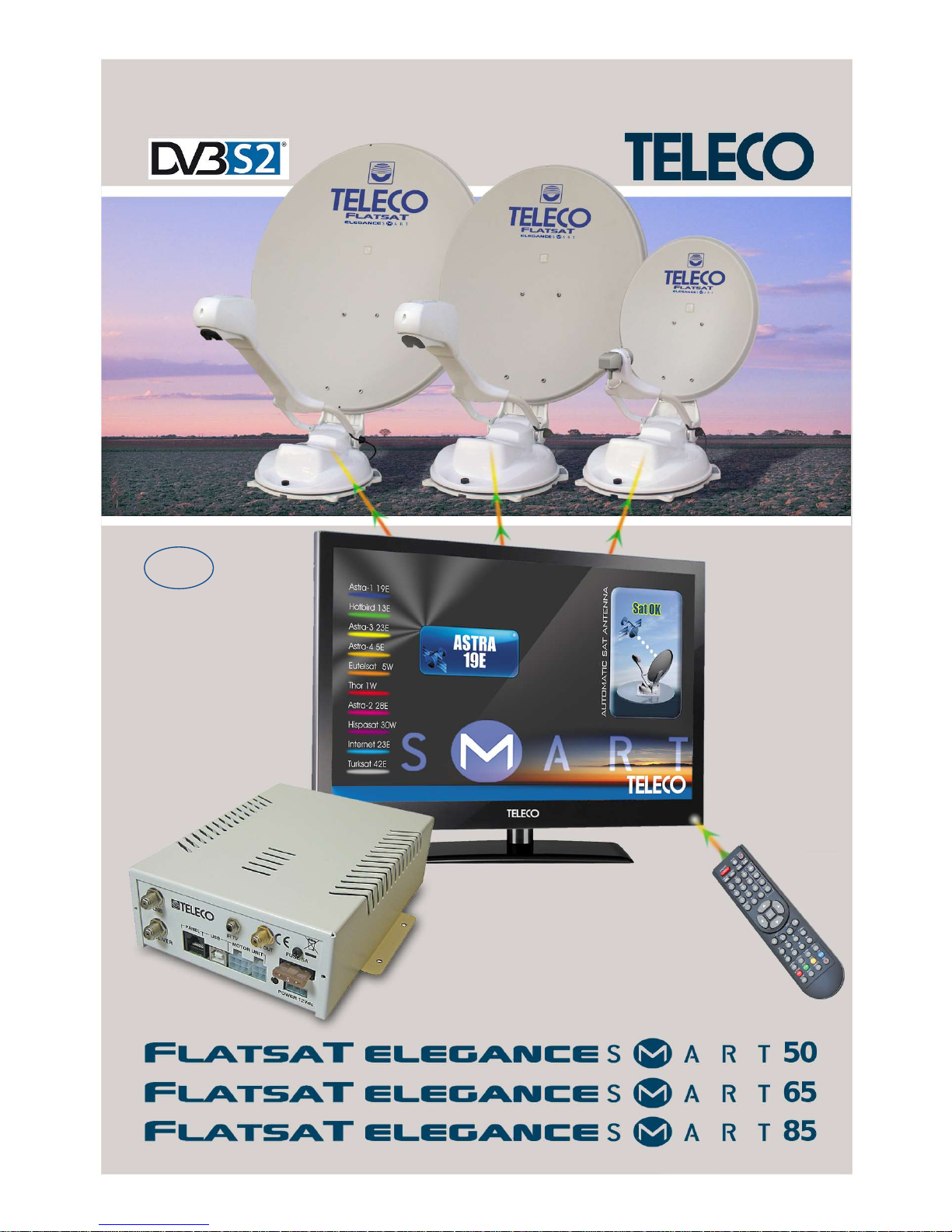
Congratulations on your purchase! Flat Sat Elegance Smart is among the most technologically
advanced products in the field of satellite TV reception. This handbook has been prepared
to provide information on how to install, use, maintain and technical specifications your Flat
Sat Elegance Smart.
For additional information, please contact your local dealer or directly the manufacturers:
TELECO s.p.a.
Via E. Majorana 49
48022 LUGO (RA)
Web site: www.telecogroup.com
Technical attendance: 899.899.856
TELECO .p.a. declines all responsibility for any errors contained in this manual. All the
contained information are up to the dates of printing and of the above-mentioned software
revisions. TELECO .p.a. reserves the right to introduce any modification made necessary by
the development of its products.
1
TABLE OF CONTENTS Page
Information.............................................................................................................................1
List of accessories.................................................................................................................3
Installation of dish on motor unit............................................................................................4
Assembly instructions............................................................................................................5
Control Unit Installation..........................................................................................................8
Flat Sat Elegance Smart – Front view...........................................................................................9
Flat Sat Elegance Smart – Rear view........................................................................................9
Connecting the Kit with Teleco TV TY2 ...............................................................................11
LNB rotation for ideal signal reception in extreme...............................................................12
Tips on the best use of Flat Sat Elegance Smart ...............................................................14
Operating the Kit with Control Unit and TELECO TV TY2 ..................................................16
Fault display ........................................................................................................................19
Troubleshooting...................................................................................................................21
Technical specifications.......................................................................................................22
Spare parts tables ...............................................................................................................23
Installed Kit..........................................................................................................................30
Recycling: with a view to reducing disposal of waste electrical and electronic
equipment as much as possible, do not throw out this end of life appliance together
with other unsorted municipal waste, but make use of a recycling centre.
2
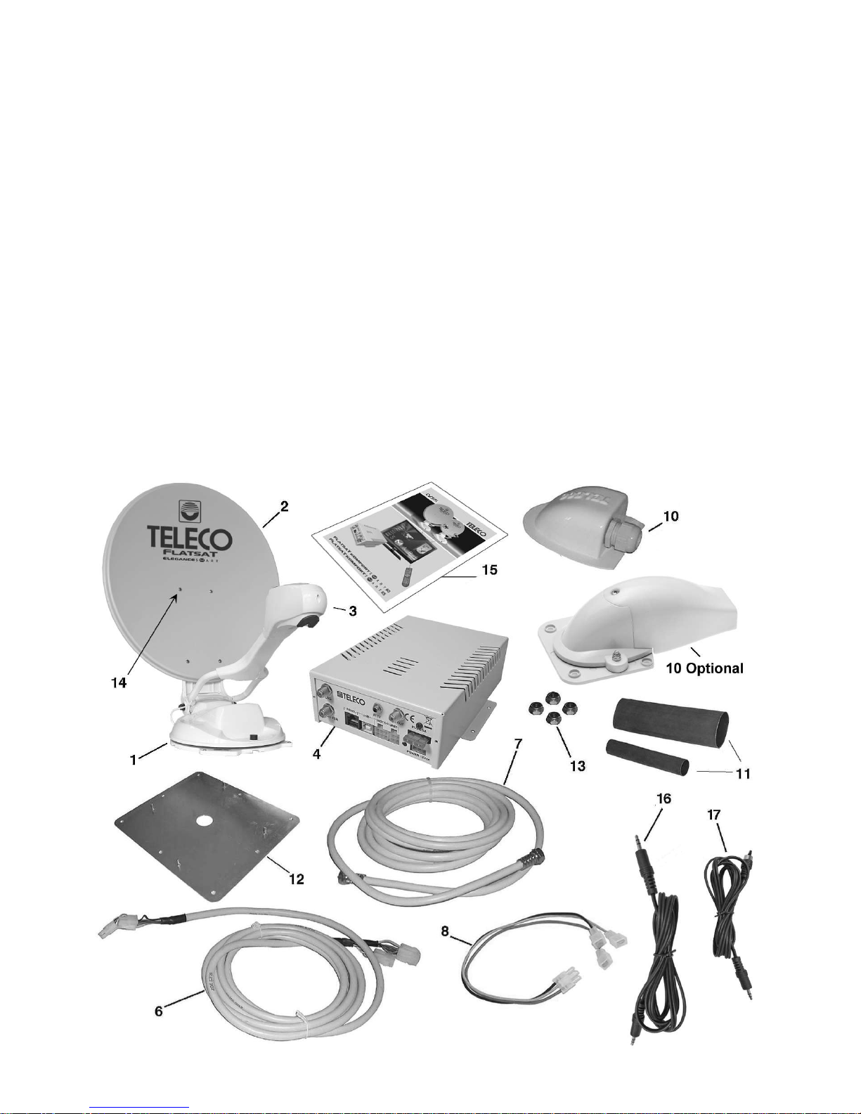
List of accessories
Flat Sat Elegance Smart is delivered inside a cardboard case that has been specially made
to protect it from knocks and pressure. The following accessories are supplied:
1 External motor-driven unit
2 50-65-85 cm dish
3 Universal LNB
4 Control Unit
6 Motor connecting cable extension
7 Coaxial cable extension for antenna signal
8 Power Supply Cable
10 Waterproof box to pass leads through
11 Heat-shrinking sheaths
12 Roof attachment plate
13 No. 4 Locknuts M6
14 No. 4 Screws and Locknuts
15 User’s manual and installation manual
16 Jack-Jack lead 2.0 m
17 RCA-Mini AV cable, 2.0 m long
3
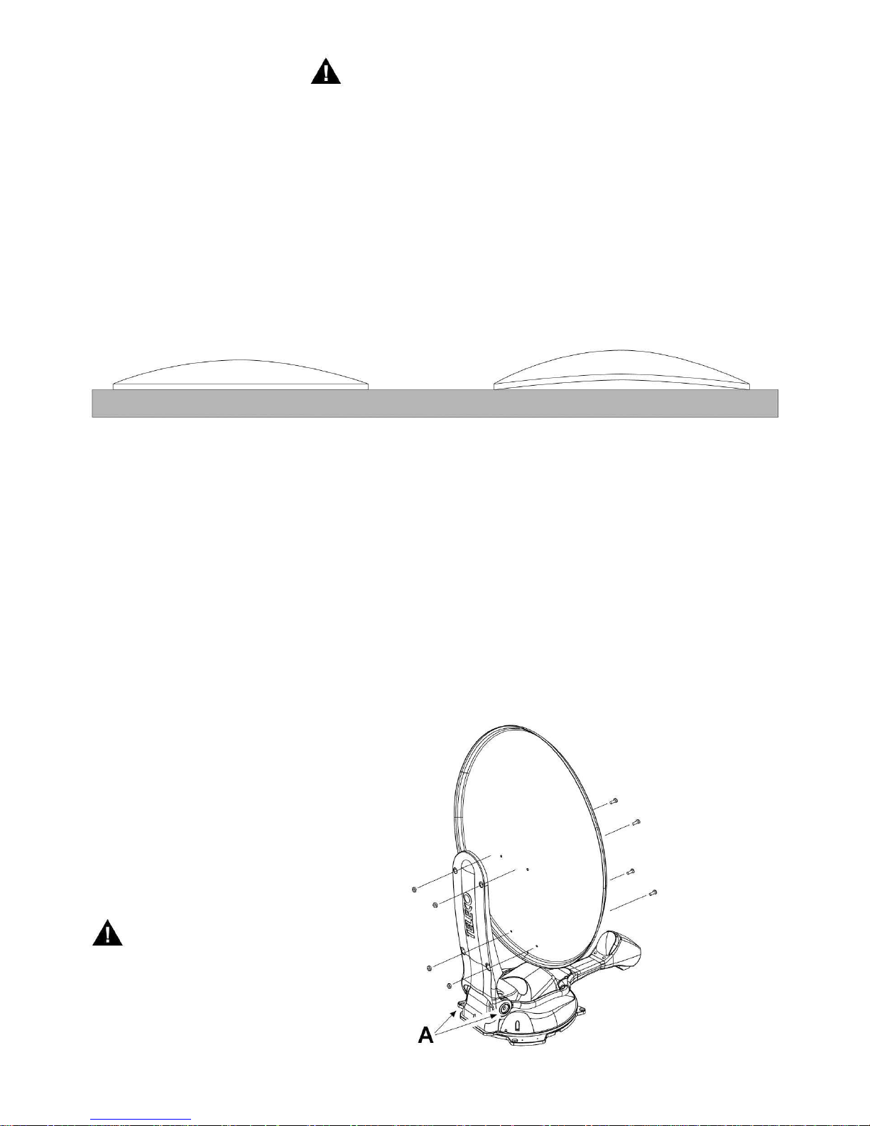
Warning:
NEVER loosen the two dish arm lock
screws (A) to attach the dish as this
will result in loss of alignment with
the antenna.
YES
NO
Important notice
Flat Sat Elegance Smart is packaged in two separate cartons for transport reasons:
a) the first package contains the driving unit with all the cables, and the control box.
b) the second package only contains the dish.
• It is important to check that the dish has not been damaged during transport when the
package is opened. In particular, check the following well:
• By resting the dish edge against a flat surface (e.g. the floor or a wall) check that it makes
contact to the surface all around. If it is not so, try and make the edge level, without denting
the dish, or call our After-Sales Service.
• After checking that everything is in order, install the dish on the driving unit as follows:
1) Connect the Control Unit and the TV as described on page 11 "Connections"
2) Press the AUTO key of the TV remote control and wait (about 30 seconds) for the
dish support arm to lift up.
3) Once you have reached the desired position, disconnect the power supply cable to
switch off the Flat Sat Elegance Smart.
4) Secure the dish to the mast and screw down the four supplied screws.
5) Turn the unit on again and wait for the antenna to close.
6) Disconnect the Control Unit,
the battery and install the driving
unit on the vehicle.
4
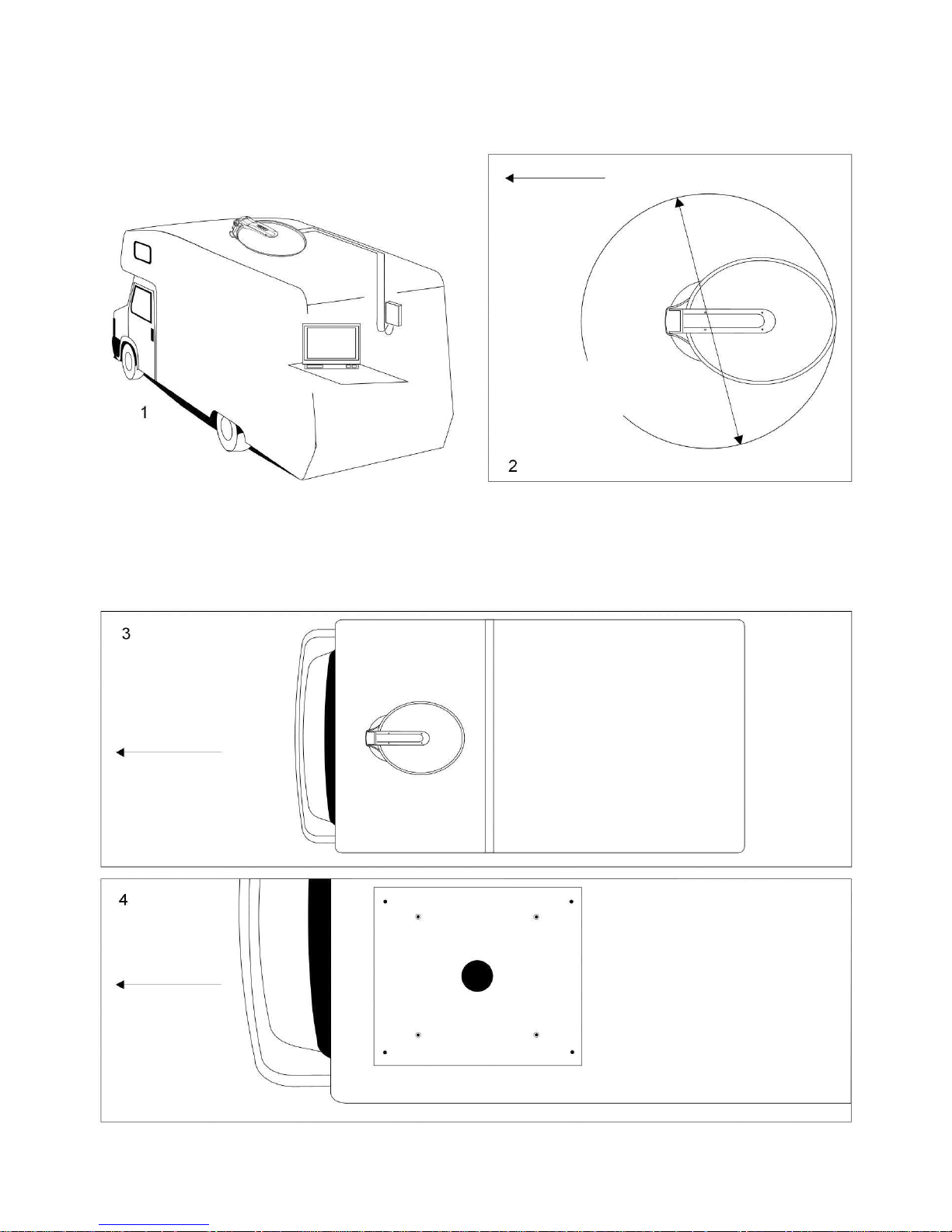
Driving direction
of the vehicle
Flat Sat Elegance Smart 50 - 90 cm
Flat Sat Elegance Smart 65 - 140 cm
Flat Sat Elegance Smart 85 - 160 cm
Driving direction
of the vehicle
Driving direction
of the vehicle
Assembly instructions
1) On the roof of the vehicle, choose a free area large enough to allow the antenna to
revolve (Fig. 2).
2) Clean the roof carefully in the area the OUTSIDE UNIT is to be installed in.
3) Remembering that the OUTSIDE UNIT must be fastened as shown on Fig. 3, position
the base plate as shown on Fig. 4, with the short side towards the driving direction
of the vehicle.
5
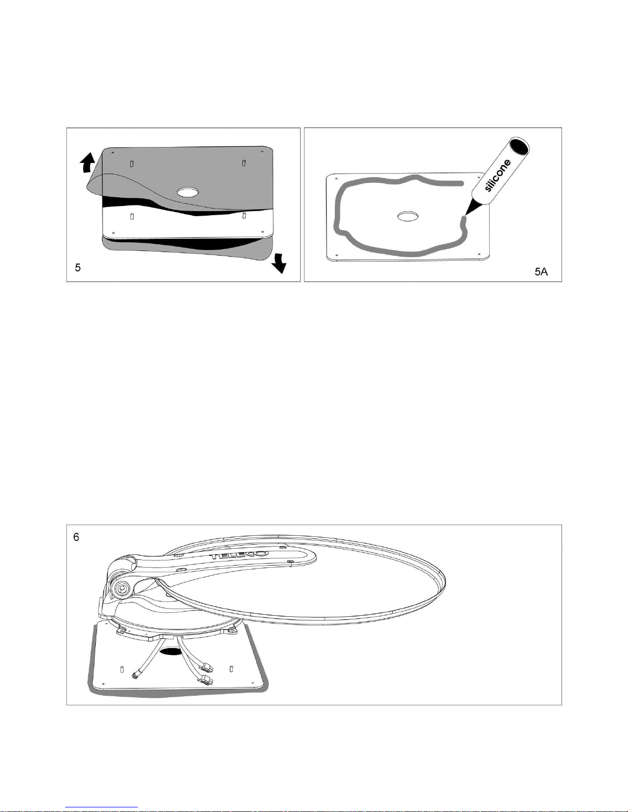
When they are present, remove the transparent films from the BASE PLATE (Fig. 5).
4) Clean the lower part of the BASE PLATE carefully, applying a layer of glue on the
whole surface (e.g. SIKAFLEX).
Outside Unit Installation
1) Fasten the OUTSIDE UNIT on the base plate and lead the two cables through any of
the 4 existing grooves, according to the position as shown on Fig. 6.
WARNING: When performing this operation, do not draw the two cables forcefully, as this
might pull them out.
5) Fasten the BASE PLATE to the roof (short side towards the vehicle driving direction).
6) Apply a layer of silicone all around the BASE PLATE in order to make it completely
waterproof (Fig. 5A)
6
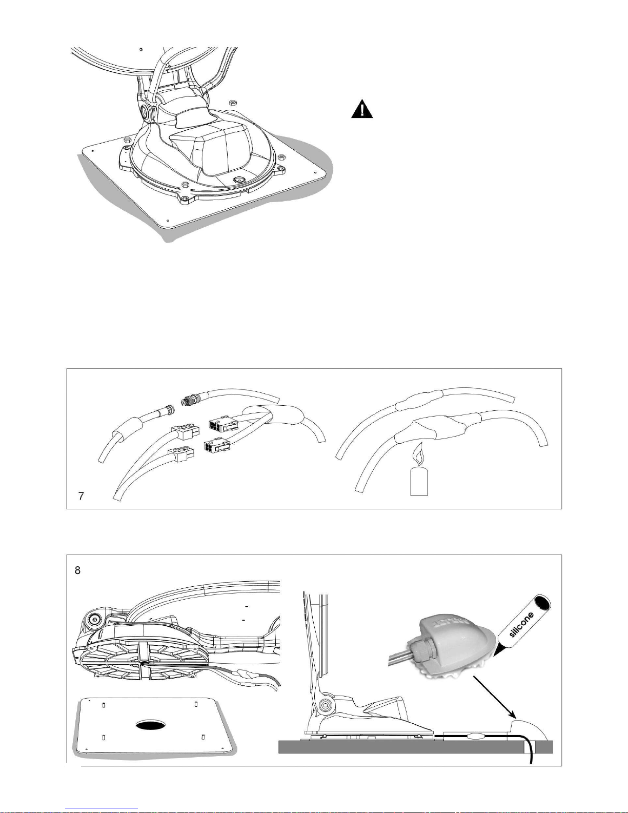
2) Accomodate the cables into a protection raceway up to the point where the cables go
into the vehicle, using the suitable supplied fairlead.
Seal the fairlead carefully so as to
prevent any infiltration by water
Connection with extension
WARNING The Grey and Black cables coming out of the Outside Unit are generally long
enough to allow for connection to the Control Unit. If it is not so, use the extension cables
and perform the following operations:
1) Connect the two cables coming from the centre of the OUTSIDE UNIT to the two supplied
extensions, waterproofing the connectors using the two pieces of heat-shrinking tube.
Caution:
to ensure ideal nut tightening and
prevent possible pin breaks,
tighten the nut with a torque
wrench set to 8 Newtons/metre
2) Fasten the external powered unit to the four stud
bolts of the plate, using the four nuts supplied with
the equipment.
7
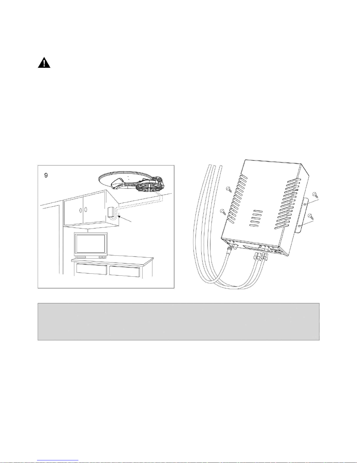
Note: Install the wall-mounted control unit with the (Grey and Black) connection cables
bent as shown in the picture. This installation tip will prevent any condensation water from
flowing down the cables into your control unit electronics - damaging it beyond repair and
voiding your warranty.
Control Unit
Control Unit Installation
1) Position the Control Unit in an easy accessible, ventilated compartment.
WARNING:
Do not install the Control Unit in areas where liquids can be spilled, since this could
cause irreparable damage.
Do not install the Control Unit in very small, unventilated compartments, since
overheating could compromise its functionality and render the warranty null and void.
2) Place the control board comando in an easily accessible, visible position.
3) Install the connection cables (Grey and Black) until you reach the
OUTSIDE UNIT installation area.
8

1) F type connector – input from LNB converter of the driving unit
2) F type connector – signal output to be connected to any satellite receiver
3) B type USB connector – connection to a PC for updating purpose
4) Connector for connection to the driving unit
5) Diagnostics button (for technical staff only)
6) Connector for power supply input from battery and safety cable
7) 5 A blade fuse
8) RCA Video connector – TV output
9) Jack Connector - IR TV
Flat Sat Elegance Smart – Control Unit rear View
1) Power-on indication LED
Flat Sat Elegance Smart – Control Unit front View
9
 Loading...